Abstract
The current study aimed to perceive and estimate the distribution of stress generated by the forces on the maxillary anterior teeth during orthodontic retraction using the bilateral mini screw implant. Finite element models were generated from the three-dimensional (3D) reconstruction of the maxillary arch via cone–beam computed tomography (CBCT). These models imitate the retraction of maxillary anterior teeth with the mini screw placed as the skeletal anchorage. The titanium mini screw of 1.3 mm × 8 mm dimension was placed at a height of 9 mm between the first molar and second premolar on both sides of the maxilla. A nickel titanium (NiTi) coil spring of 9 mm length was attached from the mini screw implant to the power arm which generated a force of 250 gm/side. Two different power arms were placed between the lateral incisor and canine at a height of 4 mm (group 1) and 8 mm (group 2), respectively. There were no significant differences observed when the stress values were compared to the left side and the right side in group 1 with a power arm of 4 mm. In group 2, the stresses around the lateral incisors were found to be on the higher side when compared with the central incisors and canines. The length of the power arm shows no significant difference in stress distribution pattern on the left and right sides except for stresses moving from the canine region to the lateral incisor region with the increase in power arm height.
1. Introduction
Anchorage has always been a prime concern in orthodontic procedures, especially when multiple teeth are moved simultaneously. Anchor teeth resist any undesirable tooth movement, and loss of anchorage might have an unfavorable effect on the orthodontic treatment outcomes [1]. Many appliances and techniques have been used commonly to prevent anchorage loss such as trans palatal bars, extraoral traction, Nance holding arch, and multiple teeth in an anchored unit; however, these devices have some drawbacks as these devices required outstanding patient compliance. Moreover, these devices consist of complex designs and required detailed wire bendings [2].
Three-dimensional (3D) analysis is important during orthodontic treatment to elude the adverse effects which could occur due to orthodontic forces applied in order to achieve desired tooth movement. Patients who have protruded dentition oftentimes undergo bilateral premolar extractions and retraction of the anterior teeth using maximum anchorage [2]. The treatment aim in such cases is to reduce the anterior proclination which is sometimes crucial to attain due to the stability of anchorage. Orthodontists often face difficulties with achieving maximum anchorage without experiencing anchorage loss. In the case of anchorage loss, the anchored unit acts reciprocally, which complicates the anterior-posterior correction and constrains the achievement of orthodontic treatment [3].
En masse retraction, which requires a maximum anchorage, is the most common procedure in orthodontic treatment to retract the whole arch. However, standard en masse retraction causes upper anterior teeth extrusion. Therefore, patients with deep bites, gummy smiles, or increased vertical growth might experience unfavorable outcomes [4]. Recently, mini screw implants expanded immense recognition to minimize the adverse effects of conventional en masse retraction procedures [5,6,7]. Orthodontic mini screws have been positioned between the second premolar and first molar in the buccal interdental spaces to avoid unwanted movements of the anchoring teeth during the en masse retraction procedure for maxillary anterior teeth. These orthodontic screws are easily removable without any fracture and provide stability of anchorage [8,9]. Moreover, patients’ cooperation is not necessary for mini screws’ anchorage systems, which aided orthodontists by adding continuous force, which could shorten the duration of orthodontic treatment [10].
For obtaining an ultimate result in the orthodontic treatment, controlling the movement of anterior teeth is imperative. A guided anterior teeth movement could be achieved by using power arms [11]. Displacement and rotation of the anterior teeth often occur while retracting the anterior teeth using mini screws. Moreover, the height of the power arm also changes the biomechanics that imitate the pattern of tooth movement during orthodontic treatment. Therefore, a successful tooth movement requires identifying the appropriate position of the mini screw and the power arms.
Previous studies reported about an 80% success rate of the mini screws in orthodontic treatment even though some studies mentioned the mobility observed during the treatment [12,13,14,15]. Nevertheless, few failure rates of the mini screw are inexplicable. Often times, it is related to the placement of the mini screw as well as the direction and magnitude of the mini screw. According to the different studies, forces on mini screws should persist at less than 200 gf [16,17,18,19,20], and more forces have not influenced any success of the orthodontic treatment [21]. Moreover, the surrounding hard tissue and soft tissue structures are playing an important role in the success rate of mini screws, which need to be evaluated thoroughly.
Though the success rate of mini screws is based on many parameters, many previous studies concentrated on the stress distribution of the mini screws in the soft and hard tissue. In addition, stress distribution on the trabecular or cortical bone varies from case to case. Moreover, the outside and inside ratio of the mini screw is also accountable for the variance of the stress distribution. The 3D Finite element method commenced to identify the tooth movement, distribution of stresses, and imitating the pattern of orthodontic tooth movement [22]. The first finite element study on stress distribution on the hard bone was performed in 2004, which reported that the 50-cN applied load on a mini screw was predominantly disseminated in the cortical bone [23].
Tooth movement could be analyzed non-invasively via the finite element models. Moreover, the amount of quantitative data about the physiological interaction and reactions of the individual tissue provided through the finite element study could increase the comprehension of tooth movement and different morphology of the tooth in a wide range. Finite element studies indicate that teeth with the deviated root are more prone to developing root resorption [24]. Moreover, the usage of torque during orthodontic treatment varies based on the appliances. A finite element study could also identify the influence of different materials such as different types of brackets on tooth movement [25]. Stresses are produced around the periodontium, while the orthodontic tooth movement takes place. During the treatment planning, these stresses need to be accounted for properly; otherwise, unbalanced forces might occur, which generally cause root resorption [26,27]. Therefore, stress evaluation while the combination of forces was applied during orthodontic tooth movement is necessary to comprehend during the tooth movement. Finite element model analysis is one of the approaches to study stresses that deliver orthodontists the quantitative data to recognize the physiological responses of the dentition during applied orthodontic forces.
The biomechanical effect on the retraction of upper incisors has been previously investigated through holographic interferometry, photo-elastic technique, and magnetic sensing system [28]. However, the former model constructed could hardly simulate the whole characteristics of the retraction system. The 3D finite element method is an efficient measure to investigate orthodontic tooth movement; nevertheless, most former studies focus on the single tooth or parameter analysis. Thus, the current study aimed to evaluate the stress distribution of the maxillary anterior segment during en masse retraction by using bilateral orthodontic posterior mini screw implants with different heights of hooks placed in the mesial to the canine.
2. Materials and Methods
2.1. Inclusion and Exclusion Criteria
In clear CBCT images, at least 12 maxillary teeth should present except the first premolars. Any distorted images or CBCT images with noise were excluded from this study.
2.2. Construction of the Finite Element Models
Two finite element models were generated which replicated the human upper arch or maxilla. Both models contained all the maxillary teeth along with the periodontal ligament and alveolar bone except the first premolars of either side.
A 3D quantitative analysis requires some mathematical method, making use of a model accurate both in anatomy and physical characteristics and along with the use of a computer, which has become an essential aid as far as 3D analyses are concerned. All these are available in the branch of engineering through the use of the finite element method of analysis. This involves the subdivision of the structure under consideration into a number of finite sections or elements. These elements are connected at intersections called nodes. A complex structure might contain many elements, which can be arranged in two- or three-dimensional layers, rather like bricks in a wall.
The following steps were performed for the finite element model preparation; 1. Geometric model construction, 2. A finite element model constructed from the geometric models, 3. Material property data representation, 4. Defining the boundary condition, 5. Loading configuration, and 6. Evaluation of stress distribution.
- 1.
- Construction of the Geometric Model
The aim of constructing a geometric model was to produce a mathematical model, which represented the biological properties of the teeth and the periodontium. This was represented in terms of points (grids), lines, surfaces (patterns), and volume (hyper patches). A 3D cone beam computed tomography (CBCT) scan of six anterior teeth of the maxilla was taken. An average 0.25 mm thickness periodontal ligament was considered to generate the model around the root as the periodontal ligament is consistent in all areas. The normal apical-gingival height of the alveolar bone was considered to be 14 mm. Analysis system (ANSYS) software was used for geometric modeling (Figure 1).
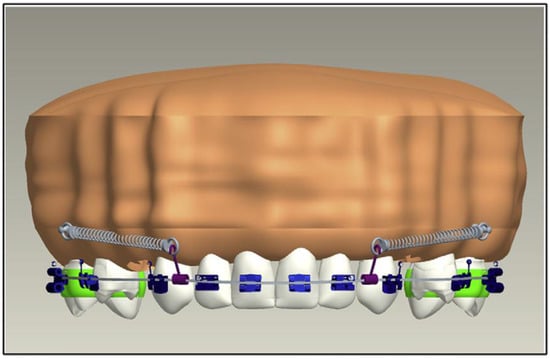
Figure 1.
Construction of the geometric model.
- 2.
- A Finite Element Model Construction from the Geometric Models
A finite model was generated from the constructed geometric models explained in step 1, which represent the finite number of nodes and elements. This process is called discretization. The main idea behind discretization is to improve the accuracy of the results. These finite elements might be tetrahedrons, rectangular points, or hexahedrons (Figure 2). These elements are considered interconnected at joints which are called nodes or nodal points. The corner nodes are called primary external nodes. The additional nodes which occur on the sides of the elements are called secondary external nodes. The secondary nodes have fewer displacements than corner nodes. The number of finite elements and nodes used is presented in Table 1.
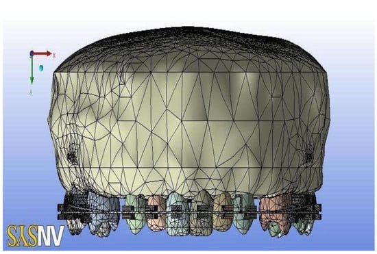
Figure 2.
Construction of the finite model.

Table 1.
Number of nodes and elements used in different variables.
- 3.
- Material Property Data Representation
The alveolar bone along with maxillary teeth are the main structures that are included in this study. Each of these structures consists of different material properties. This study used the material property from Mc Guire et al. [29] and Tanne et al. [30]. The average values for the material property are stated in the literature shown in Table 2.
Table 2.
The average values for the material property.
- 4.
- Defining the Boundary Condition
A controlled model was imitated in order to avoid the free-body motions of the models, which are known as boundary conditions. The outer surface of the bones is attached to the nodes and fixed around the tooth to prevent the free body movement of the tooth.
- 5.
- Loading Configuration and Evaluation of Stress Distribution
At these steps, forces were applied at two different points. Therefore, two different models were prepared:
- (i)
- Group 1: The maxillary teeth model consists of bonded brackets to a stainless-steel arch wire of 0.019 × 0.025 dimension. The power arm was placed between the lateral incisor and canine at a height of 4 mm. The titanium mini screw implant of 1.3 × 8 mm dimension was placed between the second premolar and first molar at a height of 9 mm. A NiTi coil spring of 9 mm length was attached from the mini screw implant to the power arm, which generated a force of 250 gm/side (Figure 3).
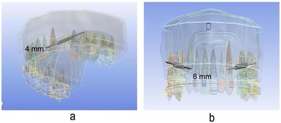 Figure 3. Placement of power arm in a different position (a) at a height of 4 mm and (b) at a height of 8 mm.
 - (ii)
- Group 2: The maxillary teeth model consists of bonded brackets to a stainless-steel arch wire of 0.019 × 0.025 dimension. The power arm was placed between the lateral incisor and canine at a height of 8 mm. The titanium mini screw implant of 1.3 × 8 mm dimension was placed between the second premolar and first molar at a height of 9 mm. A NiTi coil spring of 9 mm length was attached from the mini screw implant to the power arm, which generated a force of 250 gm/side (Figure 3).
2.3. Statistical Analysis
Stresses for each model on the application of each force were calculated with Ansys software using linear structural analysis.
3. Results
Two finite element models were generated with 4 mm and 8 mm power arm height as group 1 and group 2, respectively. Stresses generated in and around the maxillary anterior segment in group 1 were shown in Table 3, Figure 4 and Figure 5. The most stressed hard and soft bones were found around the right canines (1.168 MPa, 4.1508 MPa) and left canines (1.168 MPa, 4.055 MPa). Moreover, the most deformation was observed in the right lateral incisor (1.2499 × 10⁻³) followed by the right central incisors (1.2396 × 10⁻³). The stress values were found not to be significantly different (p > 0.05) when compared to the left side and the right side.
Table 3.
The stress generated in and around the maxillary anterior segment in group 1.
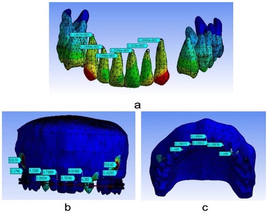
Figure 4.
Stress evaluation for group 1; (a) total deformation at 4 mm; (b) stresses on the hard bone at 4 mm; (c) stresses on the soft bone at 4 mm.
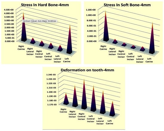
Figure 5.
Stress generation around the maxillary anterior teeth in group 1.
In addition, stresses generated in and around the maxillary anterior segment in group 2 were shown in Table 4, Figure 6 and Figure 7. The most stresses of the hard and soft bone were found around the right lateral incisors (1.0861 MPa, 3.7849 MPa) followed by left lateral incisors (1.028 MPa, 3.7854 MPa). However, unlike in group 1, deformation was observed at a similar level in almost all anterior teeth. The stress values were found not to be significantly different (p > 0.05) when compared to the left side and the right side.
Table 4.
The stress generated in and around the maxillary anterior segment in group 2.
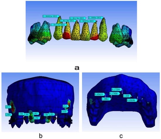
Figure 6.
Stress evaluation for group 1; (a) total deformation at 8 mm; (b) stresses on the hard bone at 8 mm; (c) stresses on the soft bone at 8 mm.
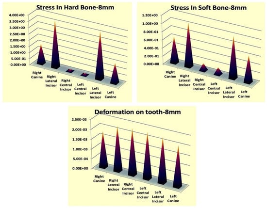
Figure 7.
Stress generation around the maxillary anterior teeth in group 2.
4. Discussion
Many designs of temporary anchorage devices (TADs) were developed in order to provide skeletal anchorage in adult orthodontic treatment, which was first proposed in 1983 [31]. After that, TADs started to be used widely in orthodontic treatments [32]. The mini screw is one of the TADs which gradually became popular due to its advantages of using it. The mini screw is easy to insert and remove without any complicated surgery during the orthodontic treatment as per requirements. Moreover, forces could be applied immediately after inserting the orthodontic treatment.
This current study was conducted on adult orthodontic patients where first premolars were extracted, and mini screws were placed between the second premolars and first molars and used for en masse retraction of the maxillary anterior teeth. Anchorage is a very perilous factor in terms of en masse retraction procedures. Orthodontists focused on maintaining anchorage during en masse retraction for the effective outcome of the treatment [3]. There are alternate approaches developed in cases of retracting the anterior teeth efficiently. Tooth-borne anchorages require additional and complicated mechanics to control the absolute anchorage.
The most common method of incisor retraction is to retract the canines followed by the four incisor teeth. However, no difference was observed between two step retraction and en masse retraction. Both procedures possessed some anchorage loss [33]. Retracting all anterior teeth with the preadjusted appliances oftentimes works as a double-edged sword for orthodontists. The advantages and drawbacks compensate each other. Whereas insignificant wire bending along with sufficient spaces work advantageously over the loop mechanics, posterior tipping and extrusion are observed in the sliding mechanics during the retraction of the anterior teeth. On the other hand, stability of the anchorage might occur while the tipping action developed into the anterior brackets.
Extra oral anchorage such as Headgear has been used to strengthen the anchorage earlier; nevertheless, the action of extra oral anchorage is patient dependent [34]. Moreover, any extra oral anchorage device is typically worn for less than 12 h, while orthodontic forces need to be applied continuously and steadily. Intra oral trans palatal arches appended the anchorage to the next stages. However, previous studies showed that trans palatal arches also cause anchorage loss [35,36,37].
Orthodontic treatment has been enhanced with the advancement of skeletal anchorage. Dental implants [37], micro screws [32,38], mini screws [31], and mini plates [39] provide skeletal anchorage during orthodontic tooth movement without the loss of anchorage. Retraction could be performed using the elastomeric chain or nickel titanium (NiTi) coil spring. However, the current study used only the NiTi coil spring for the anterior teeth retraction.
A finite element model study was conducted to determine the stress distribution of the mini screw on the soft and hard bone along with the deformation of the tooth. The finite element models were carefully created so that the models could be utilized adequately, and the general versatility of the models was preserved.
In group 1, the force application was from the titanium mini screw implant at 8 mm of height (between the second premolar and first molar) to the power arm at 4 mm of height (between lateral incisor and canine). The force was applied bilaterally at the force of 250 gm/side and was delivered by a nickel titanium coil spring. When models were analyzed in group 1 for stress generation and distribution, it was observed that, amongst central incisors, lateral incisors, and canines on both sides, maximum stress was seen around canines in hard and soft bone. The concentration of stresses in soft and hard bones around the canine is due to the initial tipping of canines, which generates maximum stress in the alveolar crest present around the canine. This current outcome is supported by various finite element model studies done in the past [40].
In group 2, the length of the power arm was increased from 4 mm to 8 mm to keep the force application near the center of resistance in the maxillary anterior segment [41]. Another reason for increasing the power arm was to keep the line of the force of application almost parallel [42]. When the model of group 2 was analyzed for stress generation and distribution, it was observed that the stresses around the lateral incisors were found to be on the higher side when compared with the central incisors and canines. This may be due to the additional curve of spee in the wires during the retraction stage to avoid a deep bite [43]. Moreover, finite element models reproduce the retraction procedure, not the complex biological process.
The current study showed that the stress values in the hard bones are greater than in the soft bones. The explanation for this might be hard bones having a higher Young’s modulus than soft bones which sustain more loads and resists more deformation than soft bones [6]. This result also complies with the previous studies [6,27]. The stress values for all bones are distantly lower than the 135 MPa, which is the fundamental tensile strength of the bone [31]. This signifies that the bone has adequate strength to defy retraction forces.
When a comparison of stress generation and distribution was done between group 1 and group 2, it was found that higher levels of stress were generated in group 1 than in group 2. This could be due to different heights of power arms which produced different force vectors that are well supported by the previous study [40]. Thus, a methodology of orthodontic tooth movement was established in the current study by all the procedures included such as finite element modeling, model analysis, and result deduction.
The current finite element model study of en masse retraction using the mini screws exhibited inconsistent distribution of stresses on teeth along with hard and soft bones. Nevertheless, stresses in the crown area are significantly greater than the stresses in the apical area of the teeth. This study explains the generation and distribution patterns of stresses in the maxillary anterior region, which need to require further clinical investigations.
A previous finite element model study on stress patterns was conducted in periodontium with three different power arm heights at 3 mm, 6 mm, and 9 mm. Moreover, orthodontic mini implants were placed at two different heights: 7 mm and 10 mm [27]. This study revealed that a high orthodontic mini-implant with a lower anterior retraction hook was required for controlled lingual tipping and, in the case of retraction with root movement, a high orthodontic mini-implant with a higher anterior retraction hook was required. Orthodontic tooth movement causes more stress on the periodontal ligament than on the surrounding bony structures. Previous studies showed that compressive stresses concentrated more on the palatal side near the apex, and the labio-cervical area of the tooth was distributed by the tensile stresses [27,44,45]. Lateral incisors experienced more stress than central incisors due to the periodontal ligament support. The reason behind this is that lateral incisors have shorter roots than central incisors [46]. Moreover, greater stresses were observed near the higher retraction hook, irrespective of the mini-implant placement [45,47]. However, the current study focused on the hard and soft bones only. Moreover, only two different heights (4 mm and 8 mm) of power arms were used in this study, and these different heights of power arms have no effect on stress distribution. As per literature searches, none of the studies placed power arms at a height of exactly 4 mm and 8 mm; therefore, direct comparison of the stress at these specific heights of power arms could not be possible.
Moreover, another similar finite element model study was conducted to identify the different tooth movements while forces were applied via a mini screw using different heights (0 mm, 3 mm, 6 mm and 9 mm) of the power arm. The study revealed that a longer power arm with the mesial placement of the mini screw decreased the anterior rotation, and the power arm at the height of 6 mm and distal placement of the mini screw had a minimal adverse effect on anterior dentition [48].
Root resorption is a common phenomenon during orthodontic tooth movement. A study on stress distribution on cementum with the finite element model reported that maximum cemental stress was observed in cervical and neck areas which gradually decrease in the apex area [8]. These areas are more prone to root resorption [49]. Moreover, greater stresses in the apex area are mostly observed during the tipping and torquing movement [50]. It assumed that, while forces were applied, the stresses were dispersed in the cervical and mid root area before the stress extends to the apex. However, the current study did not determine the stresses in the cementum and confined it to the hard and soft bone only.
In addition, root morphology is also playing an important role. A finite element model study was conducted on the stress distribution of different root morphology. The study reported that short roots show significant stress in the neck of the root area while balanced stress distribution was observed in the root with normal shape. Blunt shaped roots showed more stress distribution in the apex area of the roots, whereas dilacerated and blunt shaped roots exhibited more stresses in the middle area of the root [51]. Even though there are variant stress distributions observed, Kook et al. stated that deviated roots do not always occur in root resorption during orthodontic tooth movement [52], and genetic factors might play a vital role in root resorption during orthodontic treatment [53]. However, the current study did not focus the stress distribution on different root morphology. This study has not observed any altered root morphology during the 3D assessment; therefore, the stress distribution on different tooth roots might not change even if the stress distribution was assessed.
Therefore, it could be said that finite element studies have an enormous effect on orthodontic treatment. In en masse retraction studies, finite element study could explain how the placing of power arms at different heights modifies the anterior teeth retraction. However, in the current study, different power arms did not affect stress distribution, which could explain that the soft bone and hard bone have enough strength to resist the retraction forces by the mini screw implants. Moreover, none of the studies are free from limitations, and the current study is not exceptional. This study measured the stress distribution in soft and hard tissue. However, stress distribution in the periodontal ligament is also an important factor. In addition, the center of resistance is not calculated in the current study, which needs to be taken into consideration. On the other hand, the finite element model study simulates the mechanical law; therefore, clinical representation of orthodontic tooth movement is not sufficient to predict by the finite element models. Hence, clinical trials along with finite element model studies should be conducted.
5. Conclusions
Based on our study results, the most stressed hard and soft bones were found around the right canines and left canines. Moreover, the most deformation was observed in the right lateral incisor when the power arm was placed at a height of 4 mm. The most stresses of the hard and soft bone were found around the right lateral incisors, and deformation was observed at a similar level in almost all anterior teeth when the power arm was placed at a height of 8 mm. However, the length of the power arm shows no significant difference in the stress distribution pattern on the left and right sides except for stresses moving from the canine region to the lateral incisor region with the increase in power arm height.
Author Contributions
Conceptualization: M.J.A. and A.B.; methodology: M.J.A. and A.B.; formal analysis: M.S.K., F.A., N.R.A. and M.A.; data curation: M.J.A. and A.M.A.; writing—reviewing and editing: A.S.A., K.G., M.A. and R.O.A.; supervision: A.B.; project administration: M.J.A. All authors have read and agreed to the published version of the manuscript.
Funding
This research received no external funding.
Institutional Review Board Statement
No ethical approval was required as patients or human or animal tissues were not involved in the study.
Informed Consent Statement
Not applicable.
Data Availability Statement
Not applicable.
Conflicts of Interest
The authors declare no conflict of interest.
References
- Graber, L.W.; Vanarsdall, R.L.; Vig, K.W.; Huang, G.J. Orthodontics-Inkling Enhanced E-Book: Current Principles and Techniques; Elsevier Health Sciences: St. Louis, MO, USA, 2016. [Google Scholar]
- Mariani, L.; Maino, G.; Caprioglio, A. Skeletal versus conventional intraoral anchorage for the treatment of class II malocclusion: Dentoalveolar and skeletal effects. Prog. Orthod. 2014, 15, 43. [Google Scholar] [CrossRef] [PubMed]
- Naini, F.B.; Gill, D.S. Preparatory and postoperative orthodontics: Principles, techniques and mechanics. Orthognath. Surg. Princ. Plan. Pract. 2016, 270–312. [Google Scholar] [CrossRef]
- Antoszewska-Smith, J.; Sarul, M.; Łyczek, J.; Konopka, T.; Kawala, B. Effectiveness of orthodontic miniscrew implants in anchorage reinforcement during en-masse retraction: A systematic review and meta-analysis. Am. J. Orthod. Dentofac. Orthop. 2017, 151, 440–455. [Google Scholar] [CrossRef] [PubMed]
- Song, J.-W.; Lim, J.-K.; Lee, K.-J.; Sung, S.-J.; Chun, Y.-S.; Mo, S.-S. Finite element analysis of maxillary incisor displacement during en-masse retraction according to orthodontic mini-implant position. Korean J. Orthod. 2016, 46, 242–252. [Google Scholar] [CrossRef] [PubMed]
- Machado, G.L. Effects of orthodontic miniscrew placement angle and structure on the stress distribution at the bone miniscrew interface–A 3D finite element analysis. Saudi J. Dent. Res. 2014, 5, 73–80. [Google Scholar] [CrossRef]
- Namburi, M.; Nagothu, S.; Kumar, C.S.; Chakrapani, N.; Hanumantharao, C.; Kumar, S.K. Evaluating the effects of consolidation on intrusion and retraction using temporary anchorage devices—A FEM study. Prog. Orthod. 2017, 18, 2. [Google Scholar] [CrossRef] [PubMed][Green Version]
- Liu, T.-C.; Chang, C.-H.; Wong, T.-Y.; Liu, J.-K. Finite element analysis of miniscrew implants used for orthodontic anchorage. Am. J. Orthod. Dentofac. Orthop. 2012, 141, 468–476. [Google Scholar] [CrossRef]
- Nienkemper, M.; Wilmes, B.; Pauls, A.; Drescher, D. Mini-implant stability at the initial healing period: A clinical pilot study. Angle Orthod. 2014, 84, 127–133. [Google Scholar] [CrossRef] [PubMed]
- Shinohara, A.; Motoyoshi, M.; Uchida, Y.; Shimizu, N. Root proximity and inclination of orthodontic mini-implants after placement: Cone-beam computed tomography evaluation. Am. J. Orthod. Dentofac. Orthop. 2013, 144, 50–56. [Google Scholar] [CrossRef]
- Upadhyay, M.; Yadav, S.; Patil, S. Mini-implant anchorage for en-masse retraction of maxillary anterior teeth: A clinical cephalometric study. Am. J. Orthod. Dentofac. Orthop. 2008, 134, 803–810. [Google Scholar] [CrossRef]
- Tominaga, J.-Y.; Tanaka, M.; Koga, Y.; Gonzales, C.; Kobayashi, M.; Yoshida, N. Optimal loading conditions for controlled movement of anterior teeth in sliding mechanics: A 3D finite element study. Angle Orthod. 2009, 79, 1102–1107. [Google Scholar] [CrossRef] [PubMed]
- Chaddad, K.; Ferreira, A.H.; Geurs, N.; Reddy, M.S. Influence of surface characteristics on survival rates of mini-implants. Angle Orthod. 2008, 78, 107–113. [Google Scholar] [CrossRef]
- Liu, H.; Lv, T.; Wang, N.-N.; Zhao, F.; Wang, K.-T.; Liu, D.-X. Drift characteristics of miniscrews and molars for anchorage under orthodontic force: 3-dimensional computed tomography registration evaluation. Am. J. Orthod. Dentofac. Orthop. 2011, 139, 83–89. [Google Scholar] [CrossRef] [PubMed]
- Motoyoshi, M. Clinical indices for orthodontic mini-implants. J. Oral Sci. 2011, 53, 407–412. [Google Scholar] [CrossRef]
- Schätzle, M.; Männchen, R.; Zwahlen, M.; Lang, N.P. Survival and failure rates of orthodontic temporary anchorage devices: A systematic review. Clin. Oral Imp. Res. 2009, 20, 1351–1359. [Google Scholar] [CrossRef] [PubMed]
- Farnsworth, D.; Rossouw, P.E.; Ceen, R.F.; Buschang, P.H. Cortical bone thickness at common miniscrew implant placement sites. Am. J. Orthod. Dentofac. Orthop. 2011, 139, 495–503. [Google Scholar] [CrossRef] [PubMed]
- Kuroda, S.; Sugawara, Y.; Deguchi, T.; Kyung, H.-M.; Takano-Yamamoto, T. Clinical use of miniscrew implants as orthodontic anchorage: Success rates and postoperative discomfort. Am. J. Orthod. Dentofac. Orthop. 2007, 131, 9–15. [Google Scholar] [CrossRef] [PubMed]
- Chatzigianni, A.; Keilig, L.; Duschner, H.; Götz, H.; Eliades, T.; Bourauel, C. Comparative analysis of numerical and experimental data of orthodontic mini-implants. Eur. J. Orthod. 2011, 33, 468–475. [Google Scholar] [CrossRef] [PubMed]
- Pittman, J.W.; Navalgund, A.; Byun, S.H.; Huang, H.; Kim, A.H.; Kim, D.-G. Primary migration of a mini-implant under a functional orthodontic loading. Clin. Oral Investig. 2014, 18, 721–728. [Google Scholar] [CrossRef]
- Stanford, N. Mini-screws success rates sufficient for orthodontic treatment. Evid. Based Dent. 2011, 12, 19. [Google Scholar] [CrossRef] [PubMed]
- Janssen, K.I.; Raghoebar, G.M.; Vissink, A.; Sandham, A. Skeletal anchorage in orthodontics--a review of various systems in animal and human studies. Int. J. Oral Max. Fac. Imp. 2008, 23, 75–88. [Google Scholar]
- Chetan, S.; Keluskar, K.M.; Vasisht, V.N.; Revankar, S. En-masse retraction of the maxillary anterior teeth by applying force from four different levels–a finite element study. J. Clin. Diagn. Res. 2014, 8, 26–30. [Google Scholar]
- Kamble, R.H.; Lohkare, S.; Hararey, P.V.; Mundada, R.D. Stress distribution pattern in a root of maxillary central incisor having various root morphologies: A finite element study. Angle Orthod. 2012, 82, 799–805. [Google Scholar] [CrossRef] [PubMed]
- Papageorgiou, S.N.; Keilig, L.; Vandevska-Radunovic, V.; Eliades, T.; Bourauel, C. Torque differences due to the material variation of the orthodontic appliance: A finite element study. Prog. Orthod. 2017, 18, 6. [Google Scholar] [CrossRef] [PubMed]
- Dalstra, M.; Cattaneo, P.; Melsen, B. Load transfer of miniscrews for orthodontic anchorage. Orthodontics 2004, 1, 53–62. [Google Scholar]
- Martins, D.R.; Tibola, D.; Janson, G.; Torres Maria, F.R. Effects of intrusion combined with anterior retraction on apical root resorption. Eur. J. Orthod. 2012, 34, 170–175. [Google Scholar] [CrossRef]
- Kalia, H.; Gupta, S.; Ahuja, S.; Bhambri, E.; Goyal, A.; Sharma, R. Evaluation of stress pattern in periodontium and change in inclination during en masse retraction: Finite element analysis. J. World Fed. Orthod. 2019, 8, 153–158. [Google Scholar] [CrossRef]
- McGuire, M.K.; Scheyer, E.T.; Gallerano, R.L. Temporary anchorage devices for tooth movement: A review and case reports. J. Periodontol. 2006, 77, 1613–1624. [Google Scholar] [CrossRef]
- Tanne, K.; Yoshida, S.; Kawata, T.; Sasaki, A.; Knox, J.; Jones, M. An evaluation of the biomechanical response of the tooth and periodontium to orthodontic forces in adolescent and adult subjects. Br. J. Orthod. 1998, 25, 109–115. [Google Scholar] [CrossRef]
- Creekmore, T.D. The possibility of skeletal anchorage. J. Clin. Orthod. 1983, 17, 266–269. [Google Scholar]
- Feng, X.; Li, J.; Li, Y.; Zhao, Z.; Zhao, S.; Wang, J. Effectiveness of TAD-anchored maxillary protraction in late mixed dentition: A systematic review. Angle Orthod. 2012, 82, 1107–1114. [Google Scholar] [CrossRef] [PubMed]
- Heo, W.; Nahm, D.-S.; Baek, S.-H. En masse retraction and two-step retraction of maxillary anterior teeth in adult Class I women: A comparison of anchorage loss. Angle Orthod. 2007, 77, 973–978. [Google Scholar] [CrossRef] [PubMed]
- Li, C.; Sfogliano, L.; Jiang, W.; Lee, H.; Zheng, Z.; Chung, C.-H.; Jones, J. Total maxillary arch distalization by using headgear in an adult patient: Reconsidering the traditional strategy in modern orthodontics. Angle Orthod. 2021, 91, 267–278. [Google Scholar] [CrossRef] [PubMed]
- Kulshrestha, R.S.; Tandon, R.; Chandra, P. Canine retraction: A systematic review of different methods used. J. Orthod. Sci. 2015, 4, 1. [Google Scholar] [CrossRef] [PubMed]
- Alharbi, F.; Almuzian, M.; Bearn, D. Anchorage effectiveness of orthodontic miniscrews compared to headgear and transpalatal arches: A systematic review and meta-analysis. Acta Odontol. Scand. 2019, 77, 88–98. [Google Scholar] [CrossRef]
- Zablocki, H.L.; McNamara, J.A., Jr.; Franchi, L.; Baccetti, T. Effect of the transpalatal arch during extraction treatment. Am. J. Orthod. Dentofac. Orthop. 2008, 133, 852–860. [Google Scholar] [CrossRef]
- Deguchi, T.; Takano-Yamamoto, T.; Kanomi, R.; Hartsfield, J., Jr.; Roberts, W.; Garetto, L. The use of small titanium screws for orthodontic anchorage. J. Dent. Res. 2003, 82, 377–381. [Google Scholar] [CrossRef]
- Sugawara, J. Temporary skeletal anchorage devices: The case for miniplates. Am. J. Orthod. Dentofac. Orthop. 2014, 145, 565. [Google Scholar] [CrossRef]
- Jones, M.; Hickman, J.; Middleton, J.; Knox, J.; Volp, C. A validated finite element method study of orthodontic tooth movement in the human subject. J. Orthod. 2014, 1, 29–38. [Google Scholar] [CrossRef]
- Jung, M.; Kim, T. Biomechanical considerations in treatment with Miniscrew Anchorage. Part-I The sagittal plane. J. Clin. Orthod. 2008, 42, 79–83. [Google Scholar]
- Duaibis, R.; Kusnoto, B.; Natarajan, R.; Zhao, L.; Evans, C. Factors affecting stresses in cortical bone around miniscrew implants: A three-dimensional finite element study. Angle Orthod. 2012, 82, 875–880. [Google Scholar] [CrossRef] [PubMed]
- Kumar, K.S.; Tamizharasi, S. Significance of curve of Spee: An orthodontic review. J. Pharm. Bioal. Sci. 2012, 4, 323–328. [Google Scholar]
- Sung, S.-J.; Jang, G.-W.; Chun, Y.-S.; Moon, Y.-S. Effective en-masse retraction design with orthodontic mini-implant anchorage: A finite element analysis. Am. J. Orthod. Dentofac. Orthop. 2010, 137, 648–657. [Google Scholar] [CrossRef] [PubMed]
- Su, J.; Zhang, D.; Xu, L.; Zhong, P. 3-D finite element analysis on center of resistance of upper anterior teeth. Shan. J. Stomat. 2010, 19, 534–540. [Google Scholar]
- Hedayati, Z.; Shomali, M. Maxillary anterior en masse retraction using different antero-posterior position of mini screw: A 3D finite element study. Prog. Orthod. 2016, 17, 31. [Google Scholar] [CrossRef]
- Feng, Y.; Kong, W.-D.; Cen, W.-J.; Zhou, X.-Z.; Zhang, W.; Li, Q.-T.; Guo, H.-Y.; Yu, J.-W. Finite element analysis of the effect of power arm locations on tooth movement in extraction space closure with miniscrew anchorage in customized lingual orthodontic treatment. Am. J. Orthod. Dentofac. Orthop. 2019, 156, 210–219. [Google Scholar] [CrossRef]
- Park, H.-S.; Kwon, T.-G. Sliding mechanics with microscrew implant anchorage. Angle Orthod. 2004, 74, 703–710. [Google Scholar]
- Nilsson, E.; Bonte, E.; Bayet, F.; Lasfargues, J.-J. Management of internal root resorption on permanent teeth. Int. J. Dent. 2013, 2013, 929486. [Google Scholar] [CrossRef]
- Raza, H.; Major, P.; Dederich, D.; El-Bialy, T. Effect of low-intensity pulsed ultrasound on orthodontically induced root resorption caused by torque: A prospective, double-blind, controlled clinical trial. Angle Orthod. 2016, 86, 550–557. [Google Scholar] [CrossRef]
- Chaushu, S.; Kaczor-Urbanowicz, K.; Zadurska, M.; Becker, A. Predisposing factors for severe incisor root resorption associated with impacted maxillary canines. Am. J. Orthod. Dentofac. Orthop. 2015, 147, 52–60. [Google Scholar] [CrossRef]
- Kook, Y.-A.; Park, S.; Sameshima, G.T. Peg-shaped and small lateral incisors not at higher risk for root resorption. Am. J. Orthod. Dentofac. Orthop. 2003, 123, 253–258. [Google Scholar] [CrossRef] [PubMed]
- Nowrin, S.A.; Jaafar, S.; Ab Rahman, N.; Basri, R.; Alam, M.K.; Shahid, F. Association between genetic polymorphisms and external apical root resorption: A systematic review and meta-analysis. Korean J. Orthod. 2018, 48, 395–404. [Google Scholar] [CrossRef] [PubMed]
Publisher’s Note: MDPI stays neutral with regard to jurisdictional claims in published maps and institutional affiliations. |
© 2022 by the authors. Licensee MDPI, Basel, Switzerland. This article is an open access article distributed under the terms and conditions of the Creative Commons Attribution (CC BY) license (https://creativecommons.org/licenses/by/4.0/).