Review

A Review on Two-Phase Volumetric Expanders and Their Applications

1
Department of Energy, Systems, Territory and Construction Engineering (D.E.S.T.eC), University of Pisa, 56122 Pisa, Italy
2
Faculty of Science and Technology, Free University of Bozen/Bolzano, Piazza Università 5, 39100 Bolzano, Italy
*
Author to whom correspondence should be addressed.
Appl. Sci. 2022, 12(20), 10328; https://doi.org/10.3390/app122010328
Submission received: 23 May 2022 / Revised: 5 October 2022 / Accepted: 10 October 2022 / Published: 13 October 2022
(This article belongs to the Special Issue Volumetric Expanders for Energy Recovery and ORC Cycles)

Abstract

:
The importance of volumetric expanders has been increasing in the last decades because several studies confirmed that they lead to improved energy savings, limit the environmental impact, and reduce the energy intensity of industrial and domestic applications. In particular, several applications of the two-phase volumetric expanders, in which the operating fluid consists of liquid and vapor phases, were recently proposed. Nevertheless, the contributions in the scientific literature related to the overview of the state-of-the-art aspects of this technology are rare. For this reason, the present work discussed the potentialities and drawbacks of the available typologies of volumetric expanders that process a two-phase pure working fluid by analyzing a summary of leading studies in this field to go beyond previous efforts in the literature. The analysis revealed that twin-screw machines represent the best candidates, while reciprocating piston devices seemed the least well-adapted because of their reduced tolerance to droplets and high friction losses. Flash evaporation appeared to have the most significant impact on the expander because it affects both inlet and expansion phases, thus, determining the shape of the indicated cycle and the isentropic efficiency.

1. Introduction

An expansion process is an attractive solution in energy systems because it allows the pressure energy of a fluid to be converted into mechanical or electric energy. The machine responsible for the expansion process is the expander, whose performance determines the efficiency of the whole energy system.
Depending on the working principle, expander machines can be volumetric or dynamic. Volumetric machines operate by the exploitation of the pressure energy of the trapped fluid in order to increase the volume of the working chamber that moves a shaft. On the other hand, dynamic machines, also named turbines, act by converting the pressure energy of the fluid into kinetic energy to drive the impeller connected to a shaft.
Nonetheless, small-scale applications, e.g., below 100 kW, appear unsuitable for turbines because their rotating speed and costs increase at these sizes. As a result, these applications are suitable for volumetric machines because of their lower rotating speed, limited mass flow rates, higher pressure ratios, and reduced cost. Besides, another advantage of volumetric machines is their greater tolerance to fluid quality than turbines, thus, suggesting that a volumetric expander can process an operating fluid in the two-phase region regardless of the values of the fluid quality.
Depending on the quality of the fluid in the expansion, volumetric expanders can be single-phase or two-phase machines. A single-phase expander is a device that converts the pressure energy almost entirely in the single-phase state and only to a negligible extent in the two-phase region. A two-phase expander is a device that performs most of the expansion in the two-phase region. This general definition allows including all the practical situations in which the vapor quality is so significant as to impact the performance of the machine.
As a result, a two-phase expander must withstand high liquid fractions and minimize losses from the suction up to the discharge process. However, some general considerations suggest some advantages of two-phase volumetric machines over the homologous single-phase machines.
Indeed, depending on the working fluid, single-phase volumetric devices may require lubricating oil, thus, requiring a dedicated circuit that includes a separator and a pump. Nonetheless, the possible miscibility between the oil and the working fluid may sometimes reduce the lubrication capacity with an increase in friction and wear that worsens the efficiency and reliability of the machine.
Another drawback of single-phase volumetric machines is that their adjustment to process two-phase flows requires including other ancillary components in the plant to manage both liquid and vapor phases [1].
Conversely, two-phase volumetric expanders might avoid the need for lubricating oil, since the liquid phase of the working fluid may lubricate the surfaces. Another advantage is that the liquid phase may behave as a sealant, thus, reducing the leakages and increasing the volumetric efficiency.
Two-phase volumetric expanders can be applied to generate electrical or mechanical power in the processes for the pressure reduction of a fluid consisting of the liquid and vapor phases. The main applications are the replacement of the pressure reduction valves in several processes (e.g., in industrial steam, flash steam geothermal power plants, and natural gas transport), the replacement of the throttling valves in the vapor compression systems used for refrigeration and air conditioning, the implementation in advanced thermodynamic cycles (e.g., the trilateral flash cycle, Smith cycle, organic double-flash cycle, wet vapor ORC, and combined cooling, heating, and power), in the high-temperature heat pumps, and in the Carnot batteries (i.e., the heat-to-power processes to decarbonize the electrical energy storage sector).
Briola, in [1], found that two-phase volumetric expanders produce higher mechanical power compared to homologous single-phase machines with the same mass flow rate, inlet pressure, outlet pressure, and fluid quality at the inlet.
Nonetheless, two-phase volumetric expanders also show some drawbacks.
Thermal equilibrium between the liquid and vapor phases during the expansion process is required to determine the high performance of two-phase volumetric expanders. Due to the short time related to the two-phase expansion process, the thermal equilibrium exists if the heat exchange surface between the two phases is high. Thus, the working fluid in the two-phase expanders needs to be constituted by fine liquid particles uniformly dispersed in the vapor phase [2].
Another drawback of the two-phase volumetric expanders is the high heat exchange coefficient between the two-phase fluid and the machine’s stator, surfaces resulting in large thermal losses. Thus, suitable thermal insulation of the two-phase volumetric expanders is required to ensure their adiabaticity.
The interest in two-phase expansion initiated to increase at the beginning of the 2000s. Indeed, at the 4th IIR-Gustav Lorentzen Conference on Natural Working Fluids, several authors [3,4,5,6] proposed different solutions to increase the COP of the transcritical carbon dioxide vapor compression refrigeration cycle by using two-phase expanders. In particular, Kruse et al. [3] developed a combined compression–expansion machine suitable for this application whose advantages and drawbacks were described in a following work [6].
A prior review about the advances of two-phase expanders was published by Zhang et al. to summarize the performances of machines for transcritical CO2 vapor compression refrigeration cycles. In particular, the review was related to volumetric machines prototypes, such as piston, screw, scroll, and vane expanders, and turbomachinery [7]. Moreover, experimental investigations (Dumont et al. [8]) showed that the screw, scroll, and root expanders are more suitable for two-phase expansion than piston expanders.
On the other hand, some authors proposed to develop two-phase volumetric expanders modifying commercialized single-phase volumetric compressors [9], from which the commercialized single-phase volumetric expanders are also derived [10,11,12]. Alternatively, volumetric single-phase expanders and pumps represent other potential machines from which to derive two-phase volumetric expanders, providing that proper geometry modifications are adopted.
Despite the high potentiality of the two-phase volumetric expanders for profitable implementation in several applications, the detailed contributions in the scientific literature related to the overview of the state-of-the-art aspects of this technology are absent. For this reason, the present work discussed the potentialities and drawbacks of the available technologies of volumetric expanders operating with a single component working fluid. The aim was to go beyond previous efforts in the literature by analyzing a summary of leading studies in this field, comparing the performances of the available two-phase volumetric expanders to provide an overview of their advantages and drawbacks.

2. General Principles of the Two-Phase Volumetric Expanders

2.1. Pressure-Volume Diagram of Two-Phase Volumetric Expanders

A volumetric expander, either single or two-phase, consists of static and moving parts in which these latter parts drive a mechanical shaft.
The inner surfaces of these parts define one or more working chambers whose volume variation is due to the relative motion between static and moving surfaces.
Depending on the kinematics, the motion of the volumetric machines can be alternative as in the case of piston ones, or rotating as in case of systems based on screws, scrolls, and rotating vanes.
In operation, each chamber receives, expands, and discharges the working fluid. The pressure–volume diagram represents the trend of fluid pressure in the chamber with the corresponding volume variation during the sequence of these transformations.
The pressure–volume diagram is delimited between a maximum and minimum pressure value, and their ratio is named the pressure–expansion ratio. If we refer to a piston machine, the more general pressure–volume diagram may include a maximum of six transformations (Figure 1), as follows:
-
Suction (1–2);
-
Expansion (2–3);
-
Free exhaust (3–4);
-
Forced exhaust (4–5’);
-
Recompression (5’–1’);
-
Pressure restoration (1’–1).
The suction (1–2) occurs when the incoming fluid at constant pressure fills the chamber by flowing through a suitable opening in the stator. The cut-off grade parameter, which characterizes the suction process, is the ratio of the volume difference between the beginning and end of the suction (points 1 and 2, respectively) to the chamber displacement volume (identified as Vdispl in Figure 1). The suction ends when the opening closes, so that subsequent volume increase in the chamber causes the expansion of the trapped fluid.
The expansion process (2–3) is ideally isentropic, and it is prolonged until the maximum volume of the chamber is reached. The following two parameters characterize the expansion process: (i) the built-in volume ratio (BVR), that depends only on the expander geometry because it is defined as the chamber volume at the end of the expansion process (point 3) divided by the volume at the start of the expansion process (point 2); (ii) the specific volumetric fluid ratio (SVFR) that is determined by the operating conditions, since it is found as the ratio of the specific volume of the working fluid at the end and the beginning of the expansion (points 3 and 2, respectively).
During the successive free exhaust (3–4), the chamber pressure abruptly reduces because the discharge aperture opens to allow a spontaneous outflow of the fluid.
Later, the forced exhaust (4–5’) takes place. In particular, the volume chamber decreases while the exhaust aperture is opened so that the trapped fluid is pushed until the closure of the exhaust aperture.
The successive recompression process (5’–1’) can occur if the exhaust aperture closes before reaching the minimum volume of the chamber (point 5’). In this case, the remaining fluid in the chamber is compressed. The recompression process is characterized by the recompression grade parameter, defined as the ratio of the volume difference between the beginning and end of the recompression (points 5’ and 1’, respectively) to the chamber displacement volume (identified as Vdispl in Figure 1).
The last transformation is the pressure restoration (1’–1), which occurs when the inlet aperture opens to admit new fluid in the chamber, thus, restoring the initial value of the pressure.
In the pressure–volume diagram, the recompression process (5’–1’) and pressure restoration process (1’–1) can be absent. In particular, if the forced exhaust process ends at the minimum volume of the chamber (point 5), then the recompression process is absent and the pressure restoration process takes place (5–1). On the other hand, if the forced exhaust process ends at the proper volume of the chamber (point 5”), then the recompression process takes place (5”–1), and the pressure restoration process is absent.
On the other hand, several factors determine the configuration of the pressure-volume diagram.
The main factor affecting the configuration of the pressure–volume diagram concerns the way of the admission and discharge of the working fluid in the machine. In particular, ports in the stator drive the inlet and discharge processes in rotary machines. Conversely, valves drive these processes in piston machines. As a result, the correct operation of the valves in piston machines requires the dead volume (identified as V0 in Figure 1), while the latter is not mandatory in rotary machines due to the presence of the ports. Another factor affecting the configuration of the pressure–volume diagram is the timing of the suction and discharge processes. In rotary machines, the timing of the ports does not allow for the cut-off and recompression grades to be adapted the working conditions. Conversely, in pistons machines, these two grades can be adapted to the working conditions thanks to the timing of the valves [13,14,15].
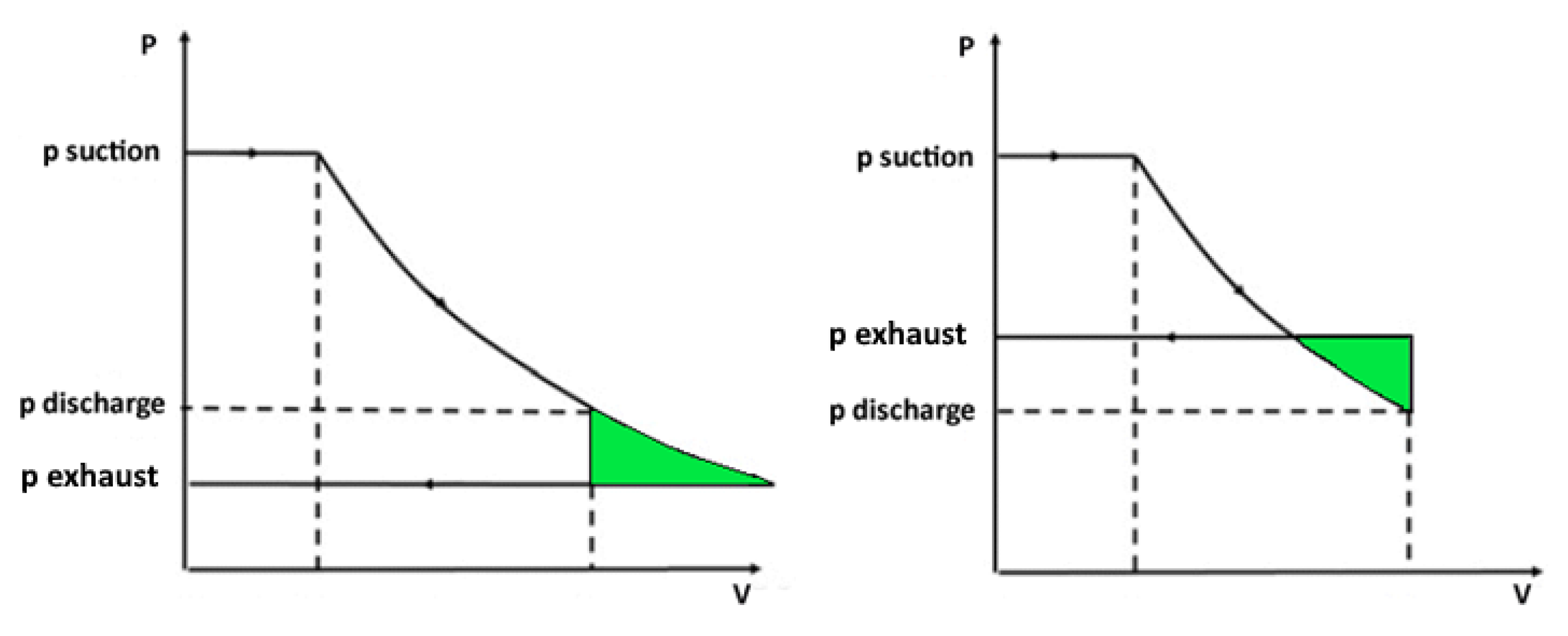
Finally, the configuration of the pressure–volume diagram also depends on the matching between the built-in volume ratio and specific fluid volumetric ratio. In particular, when these quantities match, the expansion is isentropic, i.e., the expansion losses are absent. Conversely, a mismatch causes under- or over-expansion losses. The first ones occur when the specific fluid volumetric ratio is higher than the built-in volume ratio, while the others appear in the opposite situation. In particular, the pressure of the working fluid (pdischarge in Figure 2) at the end of the expansion process is higher (under-expansion process) or lower (over-expansion process) than the pressure in the exhaust port (pexhaust in Figure 2). Some working fluid has to leave (under-expansion process) or enter (over-expansion process) the machine so that the pressure of the working fluid in the discharging chambers is equal to the pressure in the exhaust port. The related irreversibility implies the reduction in the isentropic effectiveness of the volumetric expander [10].

2.2. Performance Indicators of Two-Phase Volumetric Expanders

In the actual operation, the pressure–volume diagram deviates from the theoretical one mainly because of under-expansion or over-expansion losses, internal fluid leakages, pressure losses introduced in the valves or ports, heat transfer losses, and friction losses. In particular, these losses decrease the area of the pressure–volume diagram, thus, suggesting a reduction in the delivered power by the expander [10,16,17].
The isentropic efficiency is a performance indicator considering these losses. It is defined as the measured power delivered by the expander divided by the isentropic power that the real mass flow rate through the expander can provide [18].
On the other hand, a different performance indicator is the adiabatic efficiency. It is defined as the measured specific enthalpy difference between the inlet and outlet sections of the expander divided by the homologous isentropic specific enthalpy difference [18].
An additional performance indicator is the volumetric efficiency (otherwise called filling factor) that considers the internal fluid leakages. In particular, the volumetric efficiency estimates how the incoming fluid fills the working chamber, and it is determined as the ratio of the actual volumetric flow rate at the inlet section to the theoretical one displaced by the expander. Values of the volumetric efficiency higher than one are possible because of the internal fluid leakages [18,19].

2.3. Flash Evaporation Fundamentals in Volumetric Two-Phase Expanders

Flash evaporation is a phase change that occurs when a fluid in the liquid phase or a fluid constituted by both liquid and vapor phases suddenly undergoes a pressure reduction below its saturation pressure, thus, increasing the vapor quality.
Two-phase expanders experience flashing phenomena during the intake and expansion processes because of their pressure reductions.
A characteristic aspect of flashing phenomena in volumetric machines is that the volume of the flashing chamber varies over time. This aspect is crucial since the literature has only investigated flash evaporation in constant volume chambers (static flashing) or flashing in which the liquid film initially moves (circulatory flashing). Nonetheless, there is a lack of studies about flashing into variable volume chambers. According to our best knowledge, Kanno and Lecompte are the only ones that attempted to investigate flash evaporation in volumetric machines [20,21]. They confirmed that flash evaporation is a non-equilibrium process because it entails the formation of bubbles that increase in number and size. The non-equilibrium state depends on several physical aspects, such as atomization, nucleation, phase change, two-phase flow, droplet formation, and velocity.
The atomization transforms the liquid phase into droplets by a breakup process that consists of two steps. The first is the creation of large droplets, while the second is the further breakup of these wider droplets into smaller droplets (secondary breakup).
Bubble nucleation is the other process that can be homogeneous or heterogeneous depending on whether the bubbles appear anywhere in the liquid or exclusively at the interface between the liquid and solid surfaces of the machine. The growth of these bubbles is due to the reception of the latent heat provided by the surrounding liquid, whose temperature diminishes because of the sensible heat loss.
This mechanism stops when the temperature of the liquid reaches a saturation temperature corresponding to the existing pressure.
All these considerations suggest that the mass flow rate of the generated vapor can be found as the product of the liquid–vapor interfacial area and the net heat flux of this interface divided by the latent heat of the evaporation. Nonetheless, Kanno [20] proposed an agitation factor that replaces the liquid–vapor interfacial area and summarizes the non-equilibrium effects. Lecompte avoided the difficulties due to the modelling of flash evaporation by using a homogeneous relaxation model to predict vapor generation [21].
However, both authors underlined that the velocity with which the volume deforms is crucial because it determines the pressure reduction and the flashing time, thus, influencing flash evaporation.
Moreover, the thermal disequilibrium between the vapor and liquid phases during the two-phase expansion process penalizes the efficiency of the machines. Indeed, the pressure change causes a high volume (or density) variation for the vapor phase, resulting in high temperature variation. Conversely, the pressure change implies a negligible volume/density/temperature variation of the liquid phase. In other words, high efficiency of two-phase expanders can be obtained only in the presence of thermal equilibrium during two-phase expansion process, i.e., the temperature equality of the two phases thanks to adequate heat exchange between them. Thus, the two-phase fluid must consist of the vapor phase where fine liquid particles are uniformly dispersed [2].
As a result, the design of two-phase expanders requires the availability of numerical models capable of accurate predictions about the behaviour of a two-phase flow. For this aim, van Heule et al. [22] summarized the potential numerical techniques to describe the thermodynamic state of two-phase flows. They concluded that the numerical analysis of a flash expansion in a volumetric machine matches the experimental results when the employed numerical model considers that the liquid and vapor are isothermal. Conversely, they stated that the modelling is complicated when both phases cannot be regarded as isothermal, and this aspect still requires more attention. Consequently, these authors suggested that the technology of the expansion device affects the magnitude of the mixing between liquid and vapor phases, thus, appearing as a crucial aspect in the choice of the more appropriate numerical model.

2.4. Impact of Two-Phase Flow on Performances of Volumetric Expanders

The magnitude of the under-expansion or over-expansion losses, internal fluid leakages, pressure losses introduced in the valves or ports, heat transfer losses, and friction losses is emphasized by the presence of a two-phase flow. This encouraged some authors to assess how a two-phase fluid impacts the performances of a volumetric expander.
In 2006, Kruse et al. [6] conducted experimental tests on a modified reciprocating axial piston working with CO2. They found that the high speed (1000 rpm) prevented a thermodynamic equilibrium being reached during the expansion in the two-phase region, thus, causing a sharp pressure drop that decreased the area of the pressure–volume diagram. Their results indicated how this effect is emphasized with the decrease in suction quality, as shown by a reduction in the isentropic efficiency from 24% to 15%.
In 2015, Kanno et al. [20] experimentally investigated a two-phase reciprocating axial piston expander with water as a working fluid. They stated that the increase in the piston velocity diminished the adiabatic efficiency from 95 to 80%.
In 2017, Lecompte et al. [21] carried out experimental research to fill the knowledge gap concerning the fundamental aspects of the two-phase expansion with non-equilibrium effects. They concluded that fast acting inlet valves were necessary to obtain significant results and that the dead volume is responsible of pre-expansion losses, as it occurs in reciprocating machines.
In 2019, Wang et al. [23] proposed an experimental validated numerical model of a two-phase volumetric expander to consider how the suction valves affected the performances of the machine. They found that the pressure losses through the valves appeared as an isenthalpic process that led to the separation of the vapor and liquid phases within the working chamber. This aspect is relevant when the expander receives a liquid or a vapor–liquid mixture at the inlet ports, since the corresponding pressure drop increases the quality of the mixture.
Moreover, to the best of the author’s knowledge, two-phase volumetric machines operating with a fluid in the two-phase region under a fixed pressure ratio are characterized by the possibility of changing their SVFR for the same BVR and timing. This consideration relies on the value of the inlet quality that determines the specific volume at the suction for the same pressure level. Consequently, the same device may perform a more or less complete expansion for the same pressure ratio, thus, exhibiting different isentropic efficiency. Nonetheless, this behaviour also depends on other circumstances, such as the pressure losses through the ports, whose magnitude depends on the density.
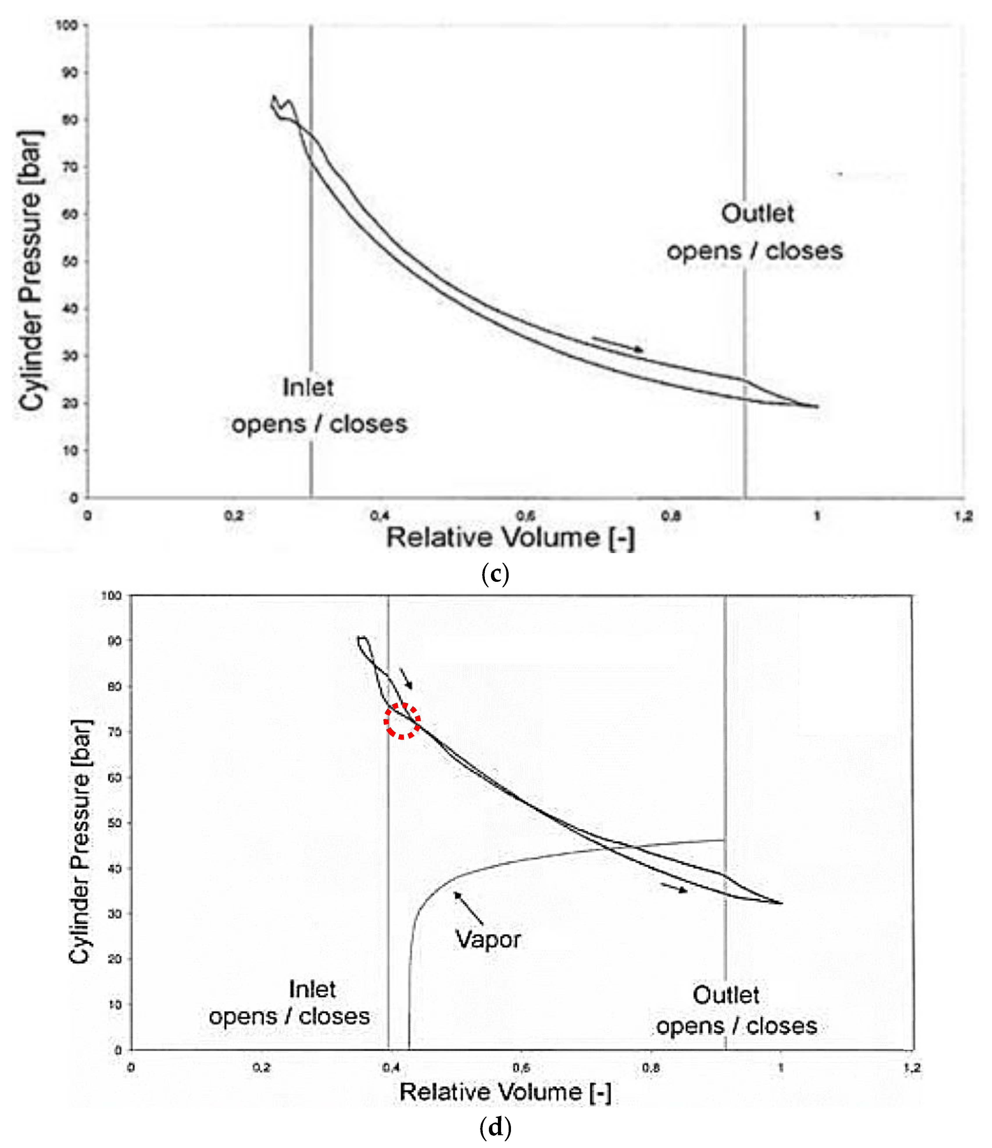
Another aspect that affects a two-phase expander occurs when the inlet vapor is single-phase, since the pressure reduction in the expansion differs depending on whether this last one occurs through the saturated liquid or saturated vapor line. Kruse et al. [6] highlighted this behaviour by testing a volumetric expansion device with CO2 as a working fluid (Figure 3a). They noted that the expansion through the left-hand side of the critical point caused a sharper pressure drop (Figure 3d) than the case in which the expansion occurred through the saturated vapor line (on the right-hand side of the critical point). This last case exhibited a pressure drop that was smoother and more similar to a complete expansion in the superheated region (Figure 3b,c). As a result, the corresponding indicated cycles varied and resulted in different isentropic efficiencies whose smaller value appeared for the expansion through the saturated liquid line. This study suggested that the initial quality value as the fluid becomes two-phase contributes to determining the isentropic efficiency value of the device.
Finally, the geometry of the device and the volume variation of the operating chamber seems to affect the tolerance of the machine to the liquid phase. Some works [8,9] pointed out this aspect by suggesting how rotating expanders exhibit a greater ability to withstand the quality than alternative machines for a variety of reasons, such as reduced lubrication and lower vibration level.

3. Two-Phase Volumetric Expanders Applications

In the literature, several applications of the two-phase volumetric expanders were proposed. In particular, these machines could be used to generate electric or mechanical power in the processes where the required reduction in the fluid pressure during the expansion process takes place mostly in wet vapor phase.
Two-phase expanders could be used for the replacement of the pressure reduction valves in industrial steam processes, e.g., food industries. In particular, the steam production takes place in a central boiler at relatively high pressure (typically in the range of 10–20 bar), and then it is transported to various sites in the factory. Here, the steam pressure is locally reduced to a lower value suitable for the processes. Thus, the higher steam density implies a smaller diameter of pipes resulting in considerable savings in the total plant cost. Thus, the opportunity exists to replace the local pressure reduction valves with expanders, and thereby recover power from the expansion process. The extracted shaft power can be used to drive a generator to produce electricity [24].
Similarly, two-phase expanders could be used for the replacement of the pressure reduction valves in flash steam geothermal power plants. Typically, the power is recovered through the circulation of the geothermal fluid in the pressure reduction valve and then a liquid–vapor separator. The separated vapor is passed through a turbine and then it is re-injected back into the ground through an injection well. Nevertheless, in such systems, problems exist with the replacement of the pressure reduction valve. First, the brines, coming from the ground, usually contain significant amounts of silicates and salts, which tend to come out of solution due to the reduction in the pressure and temperature. Second, the relatively low operation pressures and the related large specific volume of steam result in the need for very large and expensive machines [24].
Another application of the two-phase expanders is the replacement of the pressure reduction valves in the transport processes of natural gas [24].
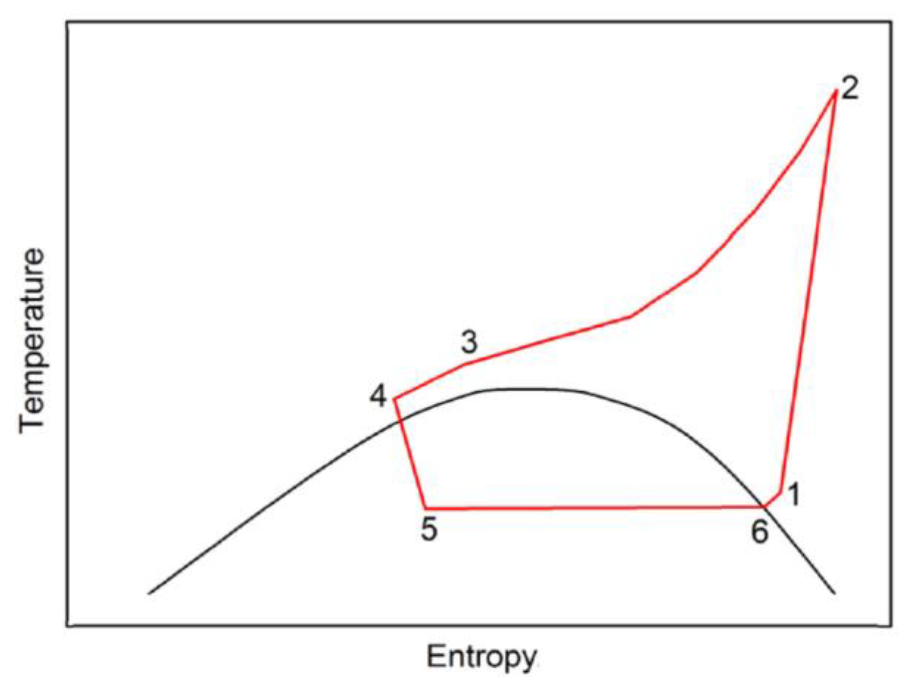
Vapor compression systems are used for refrigeration and air conditioning. The main components are the evaporator, the vapor compressor, the condenser, and the throttling valve. The latter can be replaced by a two-phase expander (Figure 4). This allows the COP increase to be obtained due to the following: (i) less electrical power needs to be supplied to the compressor thanks to the mechanical power provided by the two-phase expander. Indeed, it enables the conversion of the thermodynamic energy of the two-phase fluid, avoiding its dissipation; (ii) higher cooling power supplied to the end-user (having fixed the working fluid mass flow rate and the specific enthalpy at the evaporator outlet) thanks to the lower specific enthalpy at the evaporator inlet. Indeed, the irreversibilities in the two-phase expansion process are lower in the two-phase expander than the throttling valve, with resulting lower specific entropy and vapor phase at the evaporator inlet [24]. Moreover, the transcritical vapor compression refrigeration cycle represents a particular type of vapor compression refrigeration cycle (Figure 5), where the expansion process takes place from the supercritical phase (point 4) to the wet vapor phase (point 5). It is worth noting that the vapor compression refrigeration cycle can be alternatively used as heat pump cycle. In particular, the heat pump cycle provides the end-user (through the condenser) with thermal power at a higher temperature by exploiting the thermal power transferred at a lower temperature with a heat source.
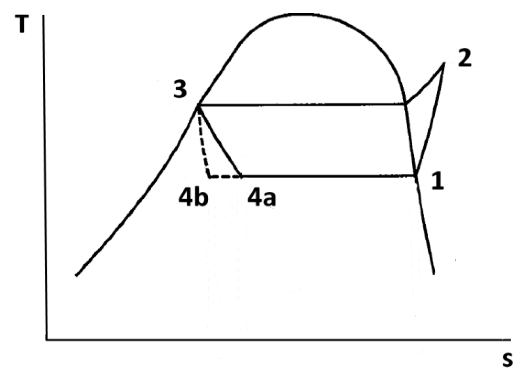
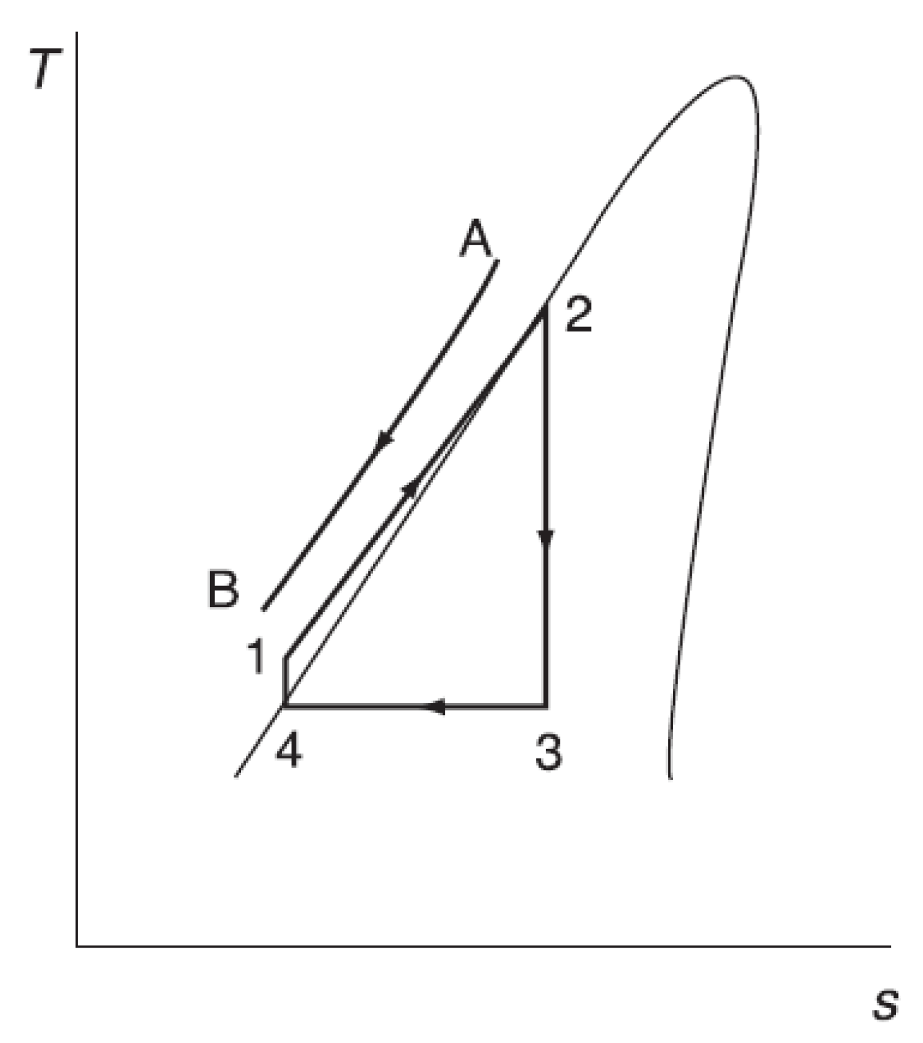
On the other hand, a two-phase expander can be used in the trilateral flash cycle (TFC, Figure 6 [25]). In the heat exchanger, the working fluid receives the thermal power transferred by the heat source, leaving in the saturated or subcooled liquid phase. The electricity production takes place in the two-phase expander, where the working fluid exits in the wet vapor phase, dry saturated phase, or superheated vapor phase. In cases of a single-phase heat source, the mean temperature difference in the heat exchanger can be modest. Thus, the low thermal irreversibility implies the production of substantial electric power and high cycle thermodynamic efficiency. The difficulty arises at higher heat source temperatures, where the volume ratio of expansion of the working fluid is too large to be realized in one stage of a two-phase expander. In particular, the second stage of a two-phase expander may then need to be too large to be cost-effective, or may be beyond current manufacturing limits.
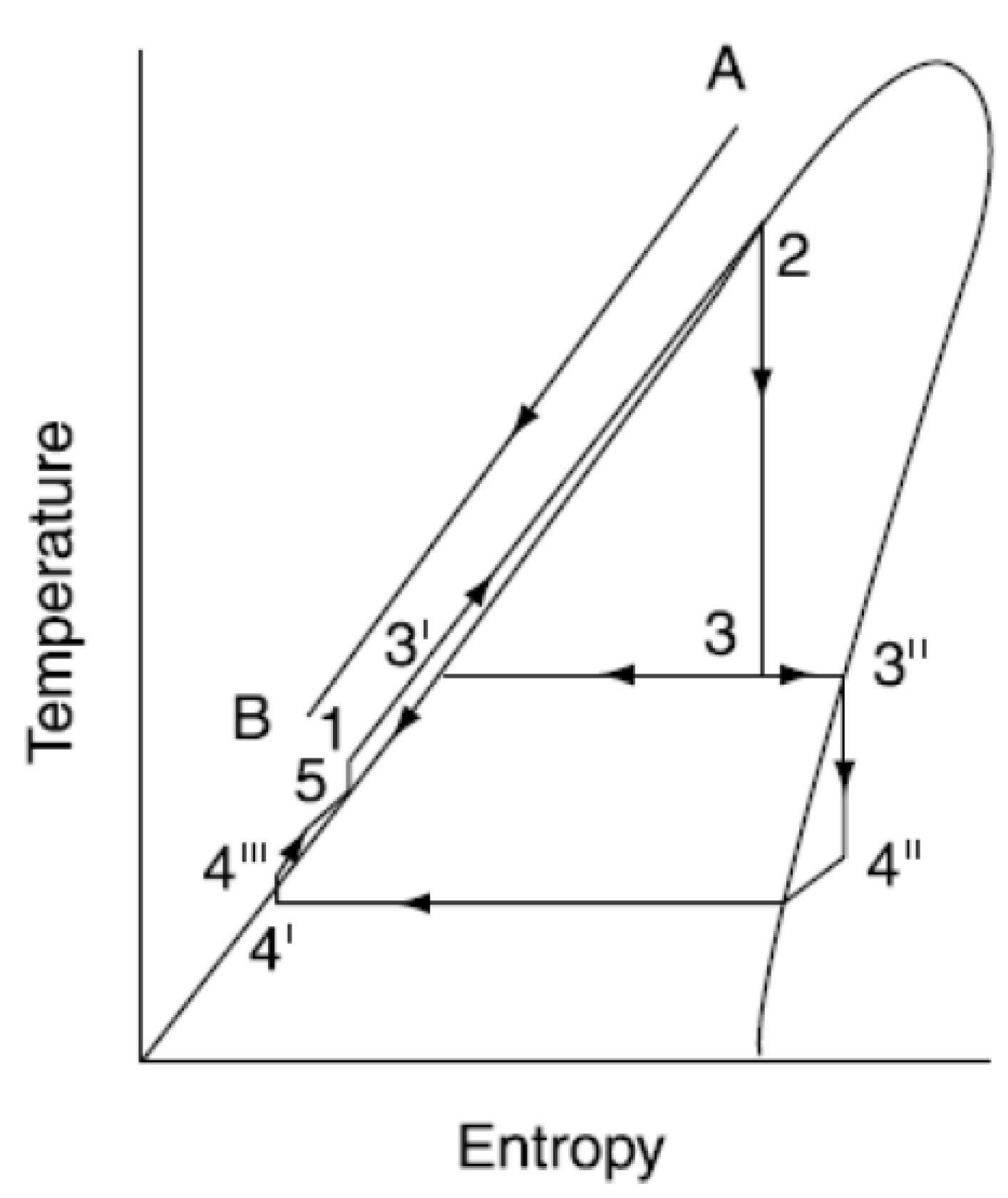
The Smith cycle shown in Figure 7 [24] was proposed to overcome the problems associated with the need for two stages of a two-phase expander for the TFC at high heat source temperatures (180–210 °C). The first expansion stage takes place in the two-phase expander (2–3), whereas the second expansion stage occurs in the single-phase expander (3”–4”). The working fluid at the two-phase expander outlet (point 3) is separated in the saturated liquid phase (point 3’) and dry saturated vapor phase (point 3”).
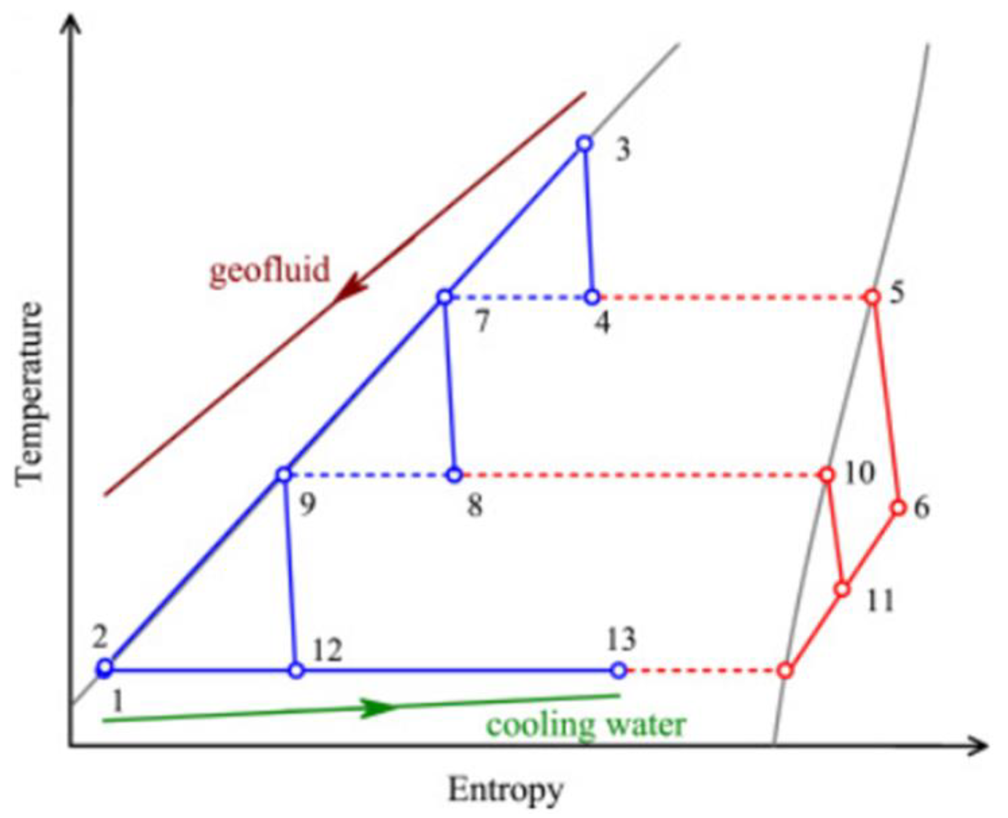
Similarly to the Smith cycle, the organic double-flash cycle adopts the separation between the liquid and vapor phases (Figure 8). In particular, this takes place in points 4 and 8. Thus, the two-phase expanders (3–4) and (7–8) are used, whereas the expansion processes (5–6) and (10–11) take place in single-phase expanders and the expansion process (9–12) occurs in the throttling valve [26].
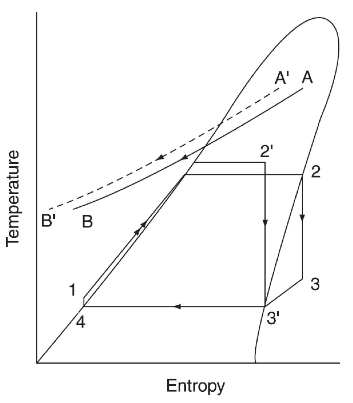
Another application of the two-phase expander is the wet vapor ORC. In particular, the working fluid is in the wet vapor phase at the expander inlet and it is in the wet vapor phase, dry saturated vapor phase, or superheated vapor phase at the expander outlet. Figure 9 [24] shows a wet vapor ORC (cycle 1-2’-3’-4) and a traditional ORC (cycle 1-2-3-3’-4). In the wet vapor ORC, the evaporation temperature can be higher with the same input thermal power. This can imply greater electric power production per unit of mass flow rate of the working fluid and, as such, higher cycle thermodynamic efficiency. Organic fluids are used in the wet vapor ORC cycle. Conversely, different working fluids (e.g., water) are used in the wet vapor Rankine cycle.
Recently, the application of two-phase expanders and two-phase compressors was proposed in an innovative combined cooling, heating, and power (CCHP) thermodynamic cycle (Figure 10). It consists of the first subcircuit (1-2-2*-3-4-5-5*-6-7-8) and second subcircuit (1-9-10-11-12), where the first and second part of the working fluid mass flow rate circulate after partition in the split (point 1). The supply of electric power to the end-user takes place thanks the expansion processes (4–5, 5*–6, 7–8 and 9–10), whereas the supply to the end-user of heating power and cooling power occur through the condenser (6–7) and evaporator (10–11), respectively [27,28,29].
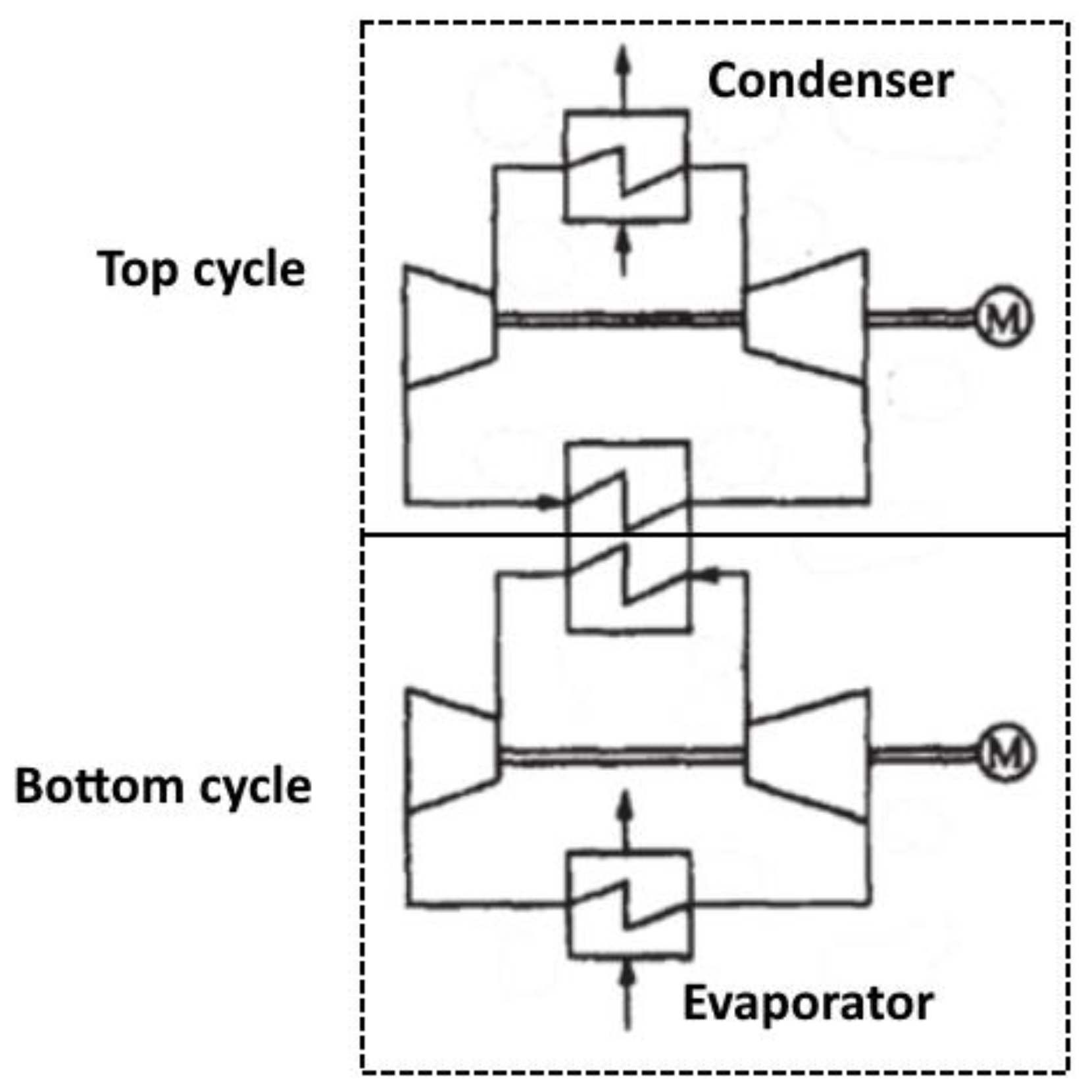
Two-phase expanders can also be used in the high-temperature heat pumps, constituted by two (top and bottom) vapor compression cycles (Figure 11). In particular, in the evaporator of the bottom cycle, the working fluid (ammonia) receives low-temperature thermal power from a heat source. In the condenser of the top cycle, the working fluid (water) supplies the end-user with high-temperature thermal power. The bottom cycle transfers thermal power to the top cycle in the common heat exchanger. A two-phase screw expander is used in lieu of the throttling valve in each top cycle and bottom cycle [30].
Finally, the application of two-phase volumetric expanders was recently proposed in the Carnot batteries to decarbonize the electrical energy storage sector. Here, a power-to-heat process (e.g., heat pump) stores excess electrical energy as thermal energy which is transferred back to electrical energy on demand by a power cycle (e.g., ORC system) [31,32].
Section 6, Section 7, Section 8 and Section 9 depict an exhaustive bibliographic literature review of two-phase volumetric expanders. In particular, the working principle is described for each type of machine (i.e., scroll, twin screw, vane, and piston). Then, the main theoretical or experimental operating conditions are outlined, such as the applications, working fluid in the presence or absence of lubricating oil, inlet and outlet conditions, machine velocity, and power. Moreover, the main geometrical quantities are summarized, such the as volume at the beginning of the expansion process and BVR (or volume at the end of the expansion process). Finally, the theoretical or experimental values of the isentropic, total, and volumetric efficiencies are reported.

4. Two-Phase Scroll Expander

4.1. Working Principle of Two-Phase Scroll Expander

A scroll expander contains two identical concentric spirals with a phase difference of 180°, in which one is fixed, and the other moves following an orbiting motion (Figure 12a). The space between these two spirals creates multiple expansion chambers with increasing volume (Figure 12b). In this case, the incoming fluid is trapped near the axis of rotation, and it expands up to the peripheral zone of the involute, where the discharge occurs. Figure 12 displays the processes evolution of the fluid inside the machine, as follows: suction (1–2), expansion (2–3), and discharge (4–5). The mechanical power is available at the crankshaft linked with the orbiting spiral [10].
The scroll expander does not need any control valves for the inlet and outlet, and it is characterized by low torque fluctuation, and low noise and vibration due to the simultaneous expansion chambers [33,34].
The volumetric efficiency is determined by radial leakages and flank leakages. They are due to the gap in the axial and radial directions between orbiting and fixed spirals, respectively [34].
The back-pressure chamber can be used for the axial sealing, and the reduction in both the thrust bearing load and of the friction at the sliding portion between the orbiting and fixed spirals [35].

4.2. Literature Review of Two-Phase Scroll Expander

The analysis of the two-phase scroll expanders mainly addressed developing their applications in vapor compression refrigeration cycles with CO2 as working fluid. The investigations in this field are described as follows.
The field of study related to the two-phase scroll expanders in the CO2 vapor compression refrigeration cycle began in the early 2000s thanks to Huff et al. [36]. In particular, they performed numerical simulations to investigate the performances of the expander for directly driving the compressor. The assumed displacement volume was 7.93 cm3 and the assumed operating conditions were an inlet pressure of 8.56 MPa, outlet pressure of 4.17 MPa, and a shaft speed of 3300 rpm. The calculated volumetric and isentropic efficiencies of the machine were 0.87–0.64 and 0.73–0.56 at leakage gap size of 5–10 μm, respectively. Moreover, the same authors [37] have developed a simulation code of different types of two-phase positive displacement expanders (including the scroll type), including the irreversibilities (valve losses, internal fluid leakages, and heat transfer losses). Requested input data to the simulation code are the geometry of the machine, working fluid properties, and the operating conditions (e.g., suction pressure, suction density, discharge pressure, and angular speed). The results of the simulation code are the volumetric and isentropic efficiencies of the machine, the thermodynamic state of the fluid during the process, the mass flow rate of the internal fluid leakages and heat transfer during the process, net mass flow rate, power output, and the forces and moments exerted by the working fluid on the machine.
In the same period, Westphalen et al. [38,39] carried out the first pioneering studies in the field of two-phase scroll expanders in CO2 vapor compression refrigeration cycle. In particular, they built the proof-of-concept prototype of the machine (with a displacement volume of 2.3 cc and volume expansion ratio of 2) based on the design concept developed by CFD and FEM analysis. Testing was carried out in the presence of lubricating oil (PAG type), at an inlet pressure of 101 bar, inlet temperature of 53.6 °C, outlet pressure of 41 bar, shaft speed of 3300 rpm, and shaft power of 637 W. The quantification of experimental performances was ongoing.
In 2006, Fukuta et al. [33] performed both theoretical and experimental investigations on a prototype of a two-phase scroll expander derived from a scroll compressor manufactured by Matsushita Electric Industrial Co. Ltd. The machine worked in the presence of lubricating oil and with a chamber volume of 1.54 cm3 at the beginning of the expansion process and BVR of 2.18. The theoretical volumetric and total efficiencies of the two-phase scroll expander were 0.85 and 0.60, respectively at inlet pressure of 10 MPa, inlet temperature of 40 °C, outlet pressure of 4 MPa and 3600 rpm. The experimental volumetric and total efficiencies were 0.80 and 0.55, respectively at an inlet pressure of 9 MPa, inlet temperature of 40 °C, outlet pressure of 4 MPa, and a shaft speed of 3500 rpm.
In 2008, Hiwata et al. [34] developed a two-phase scroll expander prototype implementing techniques to reduce the radial and flank leakages. The machine had a displacement volume of 0.5 cm3 and worked with an inlet pressure of 10 MPa, inlet temperature of 20 °C, and outlet pressure in the range 4–7 MPa. In particular, the decrease in the radial leakages was obtained by using the over-expansion. Indeed, this solution the separation of the orbiting spiral from the fixed one to be avoided, even in the case of a change in operating conditions. The decrease in the flank leakages was obtained by a mechanism using the oil-film pressure on the shaft bearing to force the orbiting spiral to the fixed spiral.
In 2008, Kohsokabe et al. [35,40] experimentally investigated a prototype of a two-phase scroll expander with an inlet volume of 2.8 cm3 and a BVR of 2, which was lubricated by polyalkylene glycol (PAG) oil. The tests were conducted to investigate the influence of several parameters, i.e., inlet pressure (6.5–9.5 MPa), inlet temperature (20–45 °C), pressure ratio (1.5–2.6), rotational speed (2000–3500 min−1), and CO2 mass flow rate (135–220 kg/h), on the prototype performances. The tests results demonstrated that the isentropic efficiency of the prototype had a maximum value equal to 0.83.
In 2008, Kim et al. [41] performed a numerical simulation of a two-phase scroll expander for directly driving the first stage compressor of a two-stage intercooled compressor. The assumed inlet volume and built-in volume ratio were 1.32 cc and 2.91, respectively. The assumed operating conditions were an inlet pressure of 10 MPa, inlet temperature of 35 °C, outlet pressure of 3.5 MPa, shaft speed of 3500 rpm and a shaft power of 0.440 kW. The calculated volumetric, isentropic, and mechanical efficiencies of the machine were 0.86, 0.86, and 0.63, respectively.
The last investigation related to the application of the two-phase scroll expanders in the CO2 vapor compression refrigeration cycles was carried out in 2010 by Nagata et al. [42]. In particular, they developed a prototype of a two-phase scroll expander for directly driving the second stage compressor of a two-stage intercooled compressor. The tests were conducted with inlet fluid in the subcooled liquid state and at the difference between inlet and outlet pressures of 1.69–4.16 MPa, with a shaft speed of 1800–3600 rpm. The experimental volumetric efficiency was 0.97–1.54 (the excess over 100% was due to the pressure loss at the inlet port and mutual, as well as close-range interference between the fixed and orbiting wraps).
An additional application of the two-phase scroll expanders was investigated in the late 2000s, in particular in the wet vapor Rankine cycle using water as working fluid.
In 2007, Kim et al. [43] developed a prototype of the machine with a displacement volume of 68.83 m3 and a double-sided configuration, i.e., two fixed spirals are placed on both sides of the orbiting spiral. Thus, the axial forces balance each other, and the thrust bearing is not required. The tests were conducted at an inlet pressure of 1.2–1.3 MPa, inlet temperature of 139–145 °C, outlet pressure of 0.11 MPa, shaft speed of 1000–1400 rpm, and a shaft power of 15 kW. The experimental maximum volumetric and maximum total efficiencies were 0.52 and 0.34, respectively. Moreover, the computer simulation showed that the volumetric and total efficiencies could be equal to 0.83 and 0.65, respectively, by the reducing the current clearance between orbiting and fixed spirals (i.e., 64 μm) by half.
In 2010, the ECR International developed two types of two-phase scroll expanders for a wet vapor Rankine cycle (with water as the working fluid) used for cogeneration. In particular, the thermal power is transferred in the condenser to a thermal fluid vector for building heating. The first type is the single-shaft configuration with maximum output power of 1.9 kW at 2800 rpm. The second type is the three-idler crank scroll expander with power of 2.5 kW in the range of 3000–3600 rpm [44].
The literature suggests that most studies about scroll machine were published between 2008–2010 and investigated CO2 transcritical cycles for heat pump and refrigeration (Table 1). The total efficiency was in a wide range between 0.30–0.60 for a rotating speed ranging from 1000–4000 rpm.

5. Two-Phase Twin Screw Expander

5.1. Working Principle of Two-Phase Twin Screw Expander

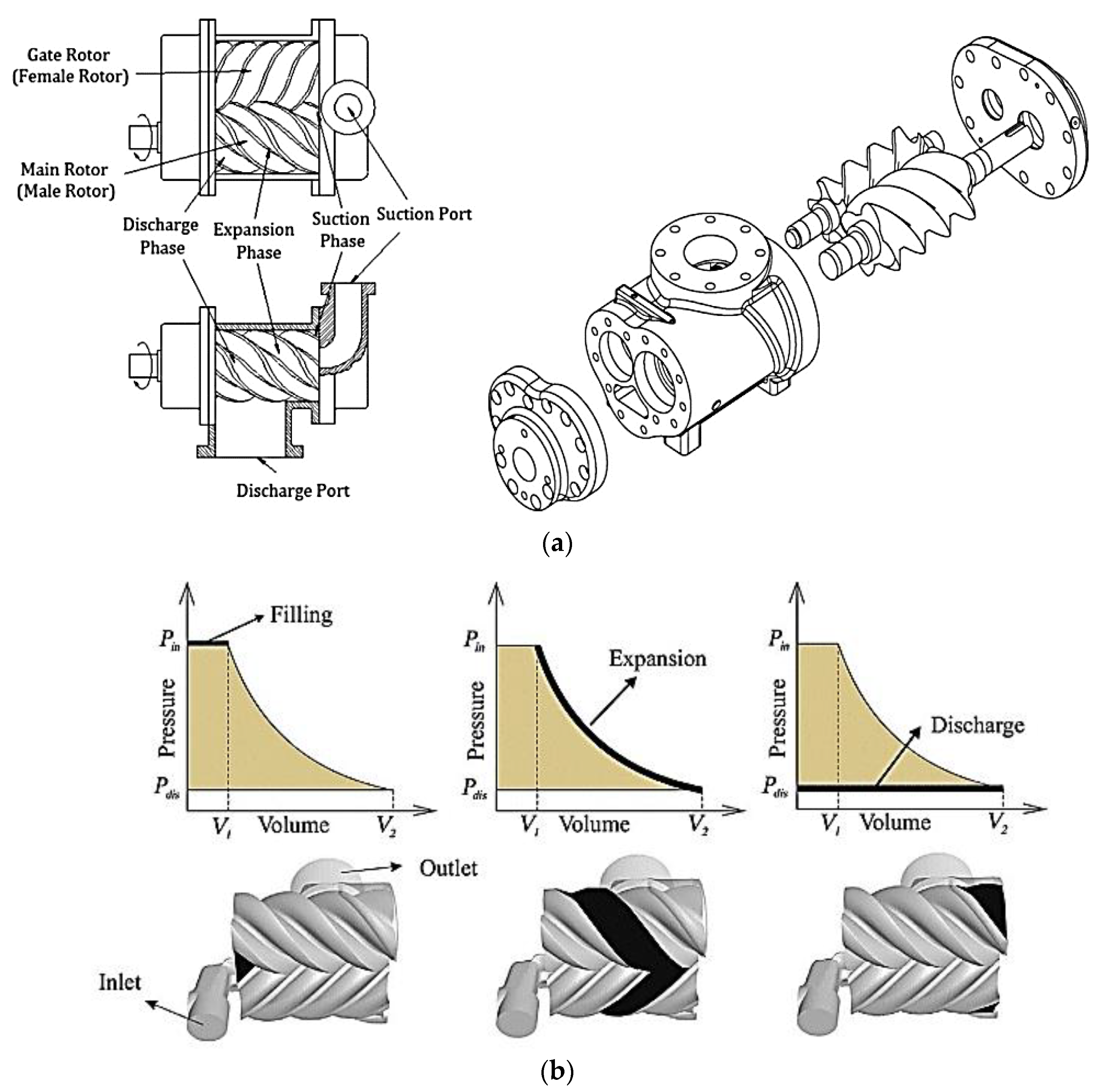
A twin screw expander (Figure 13a) contains a couple of rotors (male and female) with parallel horizontal axes, turning in opposite direction and keyed on the respective shafts. The male rotor has multiple helicoidally shaped lobes, whereas the female has multiple helicoidally shaped flutes. Both male and female rotors are supported at the end by bearings. As an alternative to using lubricating oil, a couple of timing gears synchronize the velocity of the two rotors in order to avoid their direct contact, preventing their wear. During the charging process (Figure 13b), the expansion chamber (which is volume enclosed between the two consecutive lobes, flutes, and casing) is in communication with the inlet conduit (while the outlet conduit remains closed). Then, during the following expansion process, inlet and outlet conduits remain closed, and the volume of the expansion chamber increases progressively, moving longitudinally towards the outlet conduit (Figure 13b). The fluid static pressure on the rotors causes their rotation, and in this way the conversion of thermodynamic energy into mechanical energy (available on the male rotor shaft) takes place. During the final discharge process, the expansion chamber is in communication with the outlet conduit while the inlet conduit remains closed [10].

5.2. Literature Review of Two-Phase Twin Screw Expander

The Swedish company SRM carried out pioneering work concerning two-phase twin screw expanders, which led to profiles with effective sealing and a large flow area through which the working fluid could flow. Indeed, the rotors profiles must form a good seal between each other and between the casing at all rotational positions in order to minimize internal leakages, resulting in maximization of the isentropic efficiency. Moreover, direct contact between the lobe surfaces must be avoided to prevent seizures. Most screw rotor designs used today are derivatives of the SRM rotor profiles [46].
In the early 2000s, a new family of rotor profiles (called “N” profiles) of two-phase twin screw expanders was developed. The main advantage was the low rotor contact stresses between the male and female rotors and almost pure rolling motion along with the contact band between them. Thus, timing gears were not required, provided that a low viscosity working fluid was present in the working chamber. The working fluid circulated fairly freely through the bearings using drilled passages, and internal seals were absent. Experimental tests were carried out with R-113 as a working fluid containing less than 1% lubricating oil. After several hundred hours of tests, there was no detectable wear found on bearings or rotors. The maximum isentropic efficiency was 0.76 [46].
The analysis of the two-phase scroll expanders mainly addressed developing their applications in power cycles, such as direct expansion of a geothermal fluid, TFC, and a wet vapor Rankine cycle. The review in this field is described as follows, and the main results are in Table 2.
The field of study related to the two-phase screw expanders in power cycles began in the 1970s thanks to Sprankle [25,47]. He conceived a two-phase twin screw expanders for the direct expansion of a geothermal fluid. The screw expander was of a Lysholm type, and it achieved maximum adiabatic efficiencies of only 0.53 in small-scale tests and 0.68 on a 1 MW machine. Moreover, the large size of screw expanders needed for large-scale power generation presented serious manufacturing problems.
Smith et al. provided a numerical analysis of the earlier two-phase screw expanders working with water to explain their poor performances and improve their operation [48]. For this aim, they conducted an experimental campaign to validate the model by testing several machines working with R113. These experimental results provided the pressure-volume diagram and revealed an adiabatic efficiency between 0.20–0.80 with an inlet temperature of 90–120 °C. These authors pointed out that a higher liquid fraction leads to a greater fluid density, thus, causing greater pressure drops across the ports in the intake. In the remaining lines of their study, they proposed a numerical case study to test two stages of a two-phase twin screw expander working with n-butane. They determined an adiabatic efficiency of 0.82 for an expansion drop between 137 °C and 35 °C.
In 2005, Smith et al. [49] theoretically investigated the application of a two-phase twin screw expander for direct expansion of a geothermal fluid. They found that the BVR is independent of operating conditions and exclusively depends on the size and shape of the inlet conduit geometry that can be changed with moderate costs. Low values of BVR imply higher working fluid flow rates, resulting in lower adverse effects of leakages. Nevertheless, BVR values cannot be too low, otherwise the under-expansion phenomenon takes place, resulting in a reduction in the isentropic efficiency. On the other hand, a compromise between leakages and friction losses determines the optimum rotational velocity, which also depends on the working fluid type. In particular, the velocity increase implies the decrease in the leakages and the increase in the friction losses.
In 2007, Smith et al. [50] experimentally investigated a two-phase twin screw expander with “N” profiles in a TFC using R124 as working fluid. The quality at the expander inlet was 0.95. The expander produced electric power of 22 kW with an isentropic efficiency of 0.74.
In 2014, Read et al. [51] studied a twin-screw expander in a wet vapor Rankine cycle using water. They performed the multi-variate geometrical optimization of the machine in order to maximize the output power. Experimental tests were conducted on the optimized geometry at different pressure difference values. They showed that the maximum isentropic efficiency was equal to 0.78 at nominal conditions.
In 2016, Vasuthevan et al. [52] elaborated a simulation model of a TFC operating with two-phase twin screw expander and water. It was assumed that sufficient heat transfer between the vapor and liquid phases existed to reach a stable state within a time step. The simulations showed good agreement with the experimental data, even though deviations on the power output and pressure–volume diagram took place, especially at low revolution velocities.
In 2018, Nikolov et al. [53] experimentally investigated a water injected twin-screw expander suitable for TFC. In particular, the auxiliary liquid (water) was aimed at minimizing the internal leakages within the expander and at lubricating moving machine parts.
The last investigation related to the application of the two-phase twin-screw expanders in the power cycles was carried out in 2020 by Bianchi et al. [54]. They elaborated a numerical model of a TFC with R245fa as the working fluid. The expander had a variable built-in volume ratio thanks to a sliding valve in the casing that opened an additional suction port. The simulation showed that when lowering the built-in volume ratio from 5.06 to 2.63, the volumetric efficiency increased from 0.53 to 0.77, whereas the isentropic efficiency decreased from 0.82 to 0.63 due to the under-expansion.
An additional application of the two-phase twin-screw expanders was investigated between the 1980s and early 2000s in the vapor compression refrigeration cycle, as suggested in [48] by Smith et al. to improve the COP.
Taniguchi et al. [30] carried out a numerical study on a high-temperature heat pump composed of two coupled cycles operating at two temperature levels with different working fluids. The cycle at lower temperature operated between 40 °C and 105 °C using ammonia, while the other one was between 105 °C and 180 °C by employing water steam. In both cycles, twin screw expanders replaced the throttling valves and drove twin screw compressors.
Smith et al. [55] empirically investigated the cycle using R113 and implemented the expander with built-in volume ratio of 2.85 and overall volume ratio of 12.3. The operating conditions were an inlet pressure of 8.45 bar, inlet temperature of 126 °C, outlet pressure of 3.76 bar, and an outlet temperature of 93 °C. The maximum measured isentropic efficiency was 0.76.
Moreover, Smith et al. [56] carried out a theoretical study on the “Expressor”, comprising a two-phase twin screw expander driving a single-phase twin screw compressor.
The maximum calculated isentropic efficiency of the expander in the expressor working with R134a was 0.72. Empirical tests performed by Brasz et al. [57] showed that the expander (with a built-in volume ratio of 1.85) in the expressor had an isentropic efficiency of 0.66 when working with R113. It was also demonstrated that the rotor forces created by the compression and expansion processes can be partially balanced in order to eliminate the axial forces and reduce the radial bearing forces [58].

6. Two-Phase Vane Expander

6.1. Working Principle of Two-Phase Vane Expander

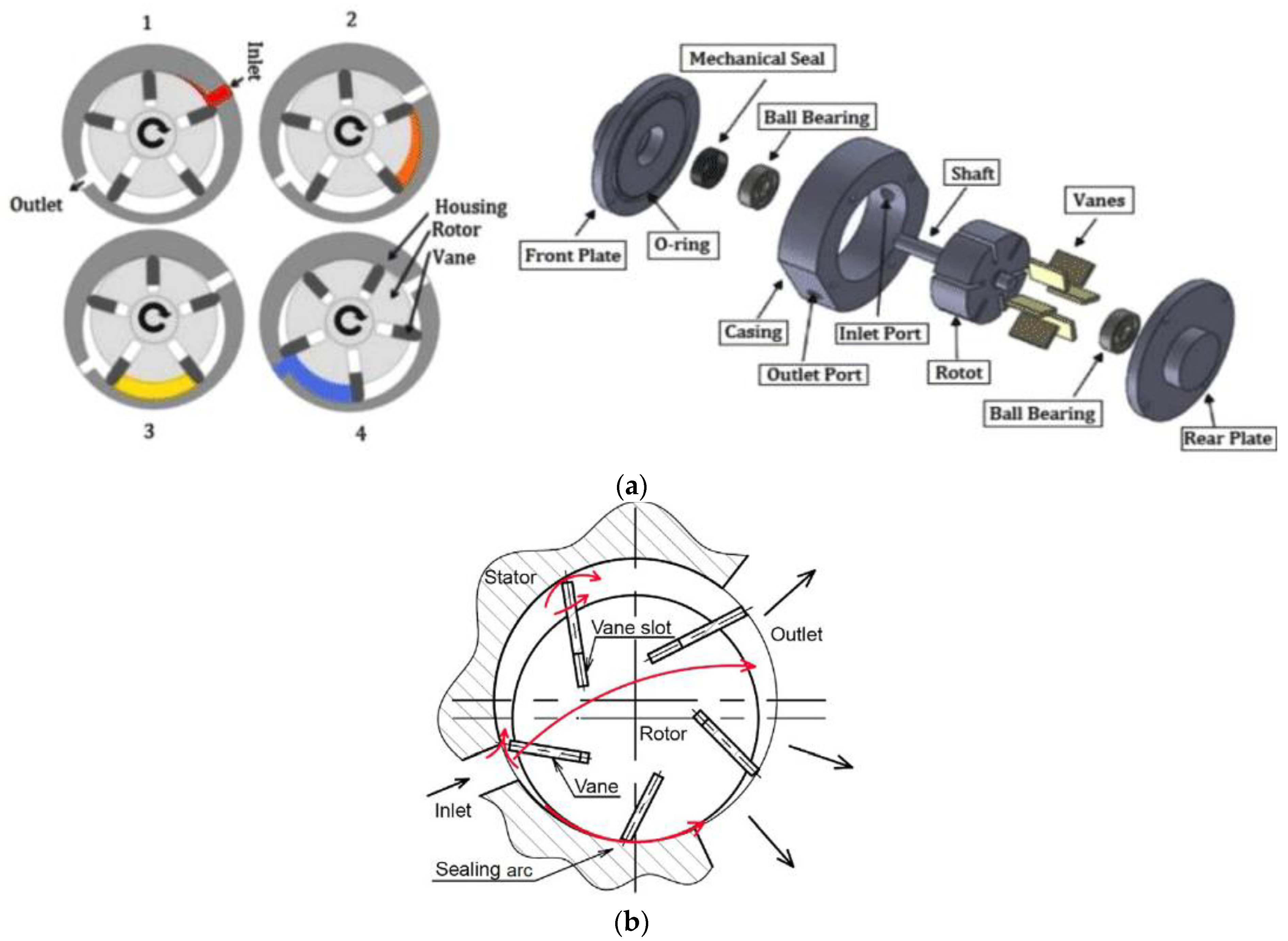
The vane expander consists of a cylindrical rotor and a cylindrical stator (Figure 14a). The rotor is offset from the center of the stator. Several slots exist over the rotor where the vanes are inserted and pushed out to the stator wall by means of spring or similar mechanism. The area between the stator wall, rotor, and two consecutive vanes realizes one rotating chamber for the working fluid (Figure 14a). The suction process takes place when the working chamber is in communication with the admission port. The expansion process begins when the contact between the working chamber and the admission port finishes, and it ends when the chamber faces the exhaust port. In this time, the discharge process starts. The pressure exerted by the working fluid on the vanes results in the motion of the rotor. During the motion of the rotor, the centrifugal force pushes each vane on the stator, thus, ensuring a contact that seals the working chamber. Nonetheless, when the pressure difference on the vane surfaces exceeds the centrifugal force, the vane moves away from the stator, thus, resulting in a loss of contact that leads to a fluid leak. These considerations indicate the occurrence of a vane chatter, which is a discontinuous contact of the vane with the stator. As a result, the vane chatter is one of the several leak pathways that affect the performance of a vane expander (Figure 14b) [59].

6.2. Literature Review of Two-Phase Vane Expander

The investigations of the two-phase vane expanders mainly aimed to further their applications in CO2 transcritical vapor compression refrigeration cycles. The following Table 3 summarizes the main performances provided in the literature.
In the late 2000s, Yang et al. provided the main contribution to the analysis of the two-phase vane expanders in the applications of CO2 transcritical vapor compression refrigeration cycles. They investigated the volumetric performance of a vane expander prototype by identifying five possible paths for the leaks [61]. This prototype was a double-acting type, i.e., two symmetric expansion chambers working in parallel where each of them had its own suction port and discharge port so that there were two suction ports and two discharge ports in total, and it employed seven vanes. The results indicated an increase in the volumetric efficiency from 0.10 at 500 rpm up to 0.6 at 3000 rpm, and that the leakage from the inlet to the outlet port was higher than the leakage from the end cover.
The same authors in [61] improved this original vane expander by making some modifications and then tested it. The average experimental conditions were an inlet pressure of 8.05 MPa, inlet temperature of 35.2 °C, outlet pressure of 4.77 MPa, and an outlet temperature of 12.08 °C, under which conditions the machine delivered a power of 0.375 kW for a rotating speed of 710 rpm. In a further study, the same researchers [62] experimentally tested the same prototype to investigate the impact of springs in the vane slots. The device operated under an inlet pressure from 7.5 to 9.0 MPa for temperatures from 32.4 to 44.3 °C and a discharge pressure in the range of 4.8–6.4 MPa, in which the discharge temperature was the saturation temperature. These tests showed that the volumetric efficiency had a maximum value of 0.29 at a rotational velocity equal to 1000 rpm, while the maximum isentropic efficiency was 0.23 at 800 rpm. The authors concluded that the inlet gas flow was responsible for the loss of contact between the vane and the stator. For this reason, they highlighted the importance of the springs to improve the volumetric efficiency by limiting the leaks.
Finally, the same authors [63] elaborated and validated the mathematical model of the vane dynamics. The results showed that the arrangement of springs in the slot underneath the vane proved to be beneficial in maintaining a tight contact between the vane and the cylinder wall and, thus, improved the working processes of the expander.
In the same period, Fukuta et al. [64] experimentally investigated a prototype with a chamber volume of 64 mm3 at the expansion process start and a built-in expansion volume ratio of 2. The inlet and outlet pressures were of 9.1 MPa and of 4.1 MPa, respectively. The measured mechanical, volumetric, and total efficiencies were 0.95, 0.7, and 0.6, respectively, at an outlet temperature of 40 °C and a rotational velocity of 2000 rpm.
The last investigation related to the application of the two-phase vane expanders in CO2 transcritical vapor compression refrigeration cycles was carried out in 2011 by Jia et al. [65]. In particular, they experimentally investigated a prototype where high-pressure gas was introduced into the vane slots (together with springs) to decrease the leakage and friction losses. This implied a significant improvement of the vane movement and a tight contact between the cylinder wall and vanes. The measured outlet power was 0.98 kW, the volumetric efficiency was 0.35, and the isentropic efficiency was 0.45 at the inlet pressure of 9 MPa, inlet temperature of 42 °C and rotational velocity of 1500 rpm, respectively.
An additional application of the two-phase twin-screw expanders was investigated between the late 2000s and early 2010s, in particular in the vapor compression refrigeration cycle. The review in this field is described as follows.
In 2009, the theoretical investigations by Mahmoud et al. [66] showed that the built-in volume ratio decreased with the increase in the intake angle independently of the number of the vanes. The latter was limited by the dynamics and mechanical strength of the rotor. Moreover, the increase in the number of vanes implied an increase in the net power output of the expander. Conversely, the reduction in the intake angle determined an increase in the net power output of the machine. In 2009, the same authors [67] proposed a methodology for the design of a two-phase vane expander by retrofitting a single-phase compressor. In particular, the internal geometry of the machine was changed, i.e., the inlet port arc spread and start, the start of exhaust port, and the number of vanes. Additionally, the stator–cylinder geometry was modified from circular to non-circular. Finally, controls and performance testing were presented.
The last analysis associated with the implementation of the two-phase vane expanders in a vapor compression refrigeration cycle was carried out in 2012 by Wang et al. [68]. They carried out a simulation study of the process with R-410a, which required a high volumetric expansion ratio during the expansion process. Modifications were implemented to a machine of a double-acting type. In particular, two asymmetrical expansion chambers worked in series and in connection via an intermediate passage. Moreover, only one suction port (in connection with the first expansion chamber) and one discharge port (in connection with the second expansion chamber) existed. The effect of lubricating oil was ignored. The produced power was around 0.5 kW, and the built-in volume ratio was up to 7.6. The maximum values of isentropic efficiency, mechanical efficiency, and volumetric efficiency were 0.62, 0.88, and 0.76, respectively.
In 2011, a different application of the two-phase vane expanders in CO2 heat pump cycles was proposed by Kim et al. [69]. The vane motion was improved by eliminating the vane jumping phenomenon. In particular, the pressurization of the vane back chamber was realized using a pressure hole connecting the vane back chamber and the expansion chamber. The authors carried out numerical simulations, assuming displacement volume to be equal to 1.69 cm3, with an inlet pressure of 9 MPa, outlet pressure of 4.5 MPa, inlet temperature of 35 °C, and a rotational velocity of 3000 rpm. The calculated expander power was 0.4 kW, whereas the calculated volumetric efficiency and total efficiency were 0.55 and 0.43, respectively.

7. Two-Phase Piston Expander

7.1. Working Principle of Two-Phase Piston Expander

In piston expanders, the head of a movable element (piston) and the surface of the stator (cylinder) delimit the variable volume of the chamber. Piston expanders can be reciprocating, rolling, and free.
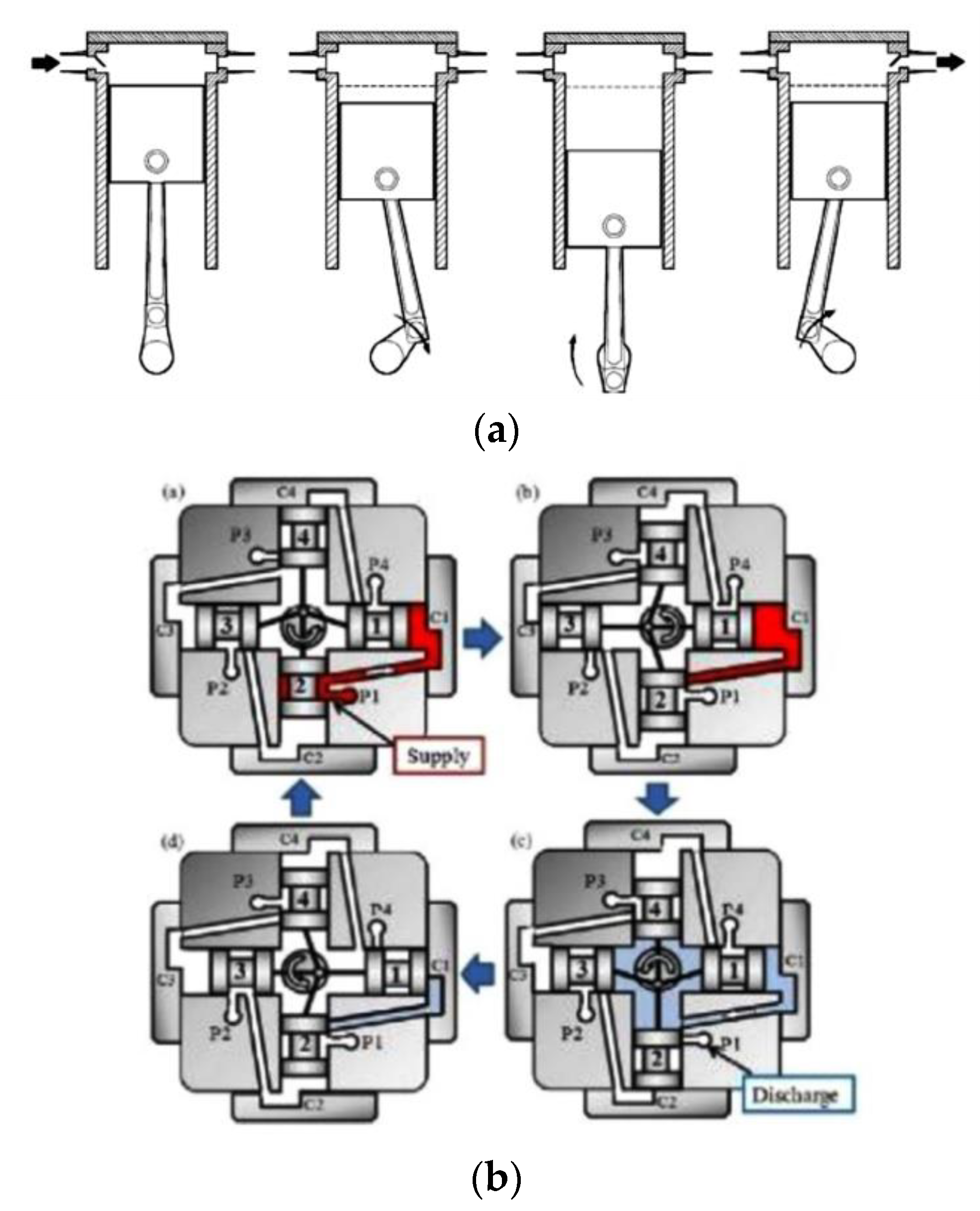
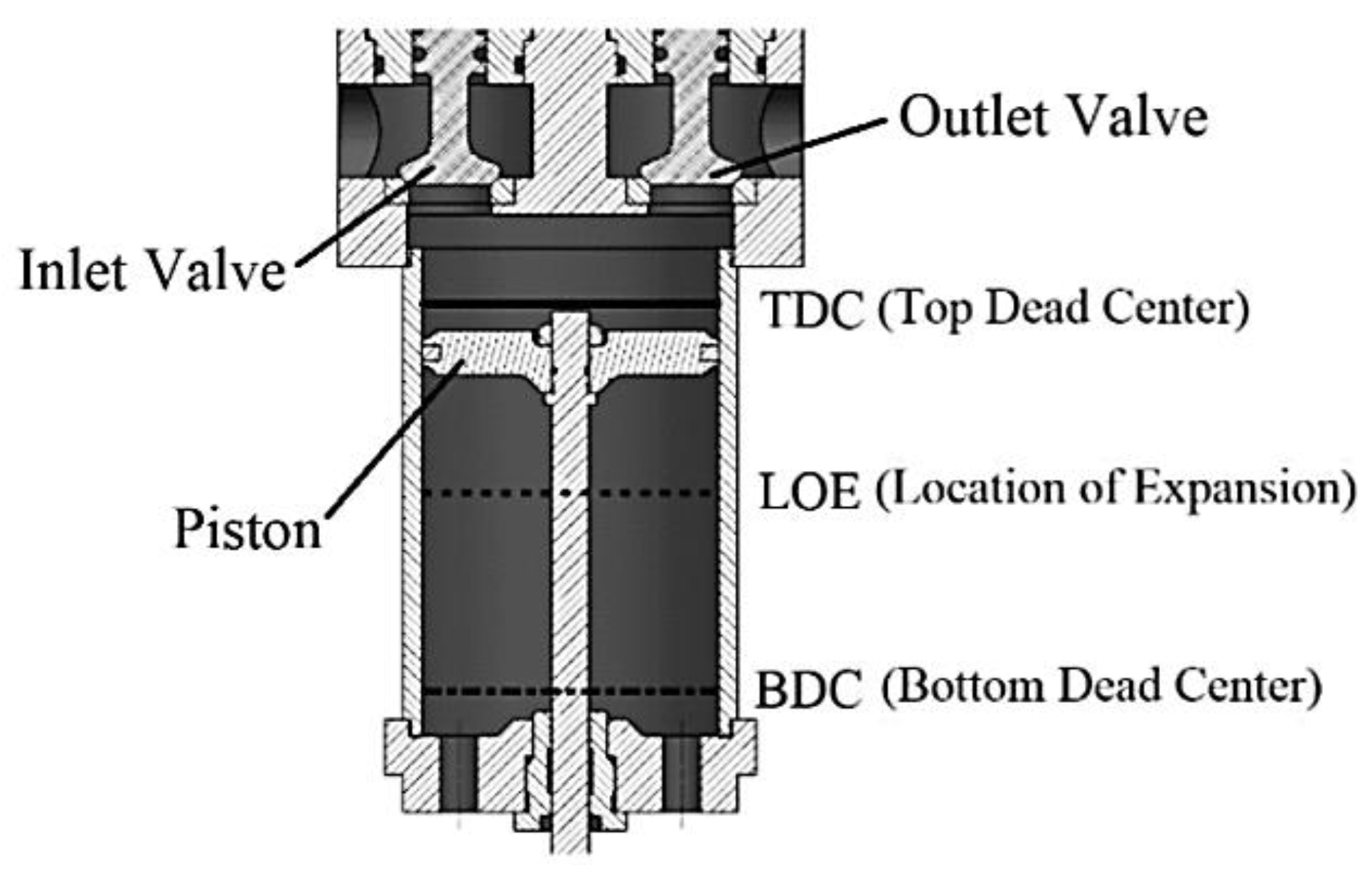
In reciprocating machines, a crankshaft converts the motion of the piston from a linear motion to a rotative one. These machines can be axial and radial depending on the arrangement of the axes of the cylinders. In axial machines (Figure 15a), the axes of the cylinders are parallel, while in the radial machines (Figure 15b), the axes are arranged in a radial configuration.
However, reciprocating piston expanders suffer some issues in terms of vibrations and noise that can be mitigated by selecting a low rotation speed and balancing weights [12].
Conversely, rolling piston systems employ a circular piston that moves over the surface of the cylinder to drive a shaft. This operation principle requires that the piston be assembled eccentrically within the cylinder to torque the shaft.
In these systems, the working chamber is a volume delimited by a part of the surfaces of the cylinder, piston, and a sliding vane that is in contact with it (Figure 16). The sizing of this working chamber depends on the length of the sliding vane, the piston and cylinder radii, and the eccentricity of the piston. An improvement in the rolling piston leads to the swing piston machine in which the vane and the piston constitute a rigid body because they are integrated together, thus, resulting in a reduction in leaks and friction.
A common aspect of reciprocating and rolling machines is the need for a crankshaft to drive a shaft. However, the crankshaft requires bearings that cause frictional losses, thus, reducing the mechanical efficiency of the machine, especially at small sizes [70]. A strategy that overcomes this issue is to implement free-piston architecture by suppressing the crankshaft system and the corresponding friction losses (Figure 17). The result is a compact crank-less machine whose advantages are compactness, leakage reduction, lower friction, and simplicity.
Several systems based on free-piston architecture have been proposed to recover energy in the literature. However, the common aspect relies on valves that admit and discharge the working fluid to drive the motion of a piston between two endpoints of the stator. The piston drives electrical actuators by membranes or a linear generator by a piston rod during its motion.

7.2. Literature Review of Two-Phase Piston Expander

The analysis of the two-phase piston expanders mainly addressed developing their applications in CO2 transcritical vapor compression refrigeration cycles, as suggested by Table 4.
In 2004, Li et al. [72] developed a two-phase rolling piston expander considering several aspects, such as sealing, friction losses, and timing of the intake. Experimental tests were carried out at an inlet pressure of 7.34 MPa with a rotating speed between 600–2200 rpm, obtaining the isentropic efficiency of 0.32.
In 2005, Nickl et al. [73] developed a two-phase three-stage expander based on a free piston architecture. This machine was experimentally tested between a suction pressure of 80 MPa and a discharge pressure of about 50 MPa. They suggested that the expansion in the two-phase region did not cause any problems, and the isentropic efficiency was in the range of 0.65–0.70, depending on the operating conditions.
In 2005, Baek et al. [74,75] built a two-phase reciprocating axial piston machine by modifying a commercial small four-stroke, two-piston gasoline engine in which the displacement of each cylinder measured 13.26 cm3. However, the original crankshaft was modified to obtain a proper out-of-phase firing that limited the mechanical inertia. This solution ensured that the piston in the expansion stroke drove the other piston through the exhaust stroke. Other modifications concerned the valves and the cylinder head to provide acceptable volumetric efficiency and a proper BVR. This expander was lubricated by oil and provided an isentropic efficiency of about 0.10 under a pressure ratio of 2.07 for a rotating speed 114–120 rpm. The low efficiency probably depended on the leaks from the working chamber.
In 2006, Yang et al. [76] proposed a two-phase two-stage two-cylinder rolling piston expander, whose main characteristic was the removal of the suction valve to ensure a continuous expansion process. The authors elaborated a numerical model of this machine to assess the forces on the crankshaft, the flow velocity, and the shape of the pressure–volume diagram. In the numerical model, the first and second expansion unit displacements were 0.49 and 1.29 cm3, respectively, while the boundary conditions were an inlet pressure of 9 MPa, an inlet temperature of 35 °C and a discharge pressure of 3.48 MPa. The results indicated that the pressure decreased slowly in the expansion when the CO2 entered the vapor–liquid two-phase region. Nonetheless, this study did not report any values for the isentropic efficiency.
In 2009, Li et al. [77] investigated the potentialities of a two-phase rolling piston expander by developing and testing a prototype that consisted of one cylinder with a particular suction system and reached a peak of isentropic efficiency of 0.587.
The last analysis associated with the implementation of the two-phase piston expanders in CO2 vapor compression refrigeration cycles was carried out in 2010 by Tian et al. [78]. They proposed a two-phase rolling piston expander designed for an inlet pressure of 9 MPa, an inlet temperature of 35 °C, a discharge pressure of 3.9 MPa, and a rotating speed of 1500 rpm The experimental results revealed that this machine exhibited an isentropic efficiency that increased from 0.30 at around 600 rpm to 0.45 at 1500 rpm. However, a further increase in the rotating speed up to 1800 rpm caused a reduction in the isentropic efficiency, which became 0.42.
An additional application of the two-phase piston expanders was related to the power cycles. The review in this field is described as follows.
In 2016, Li et al. [77] proposed a free piston device with a linear generator as suitable for ORC systems thanks to some advantages, such as compactness and flexibility.
In 2019, Wang et al. [23] simulated a TFC operating with water as a working fluid and implemented a two-phase reciprocating axial piston expander whose volume measured 4.9 × 10⁻³ m3. Their simulations considered inlet and condensation temperatures of 373 K and 303 K, respectively, and a rotating speed of between 200 and 1500 rpm. They found a decrease in the isentropic efficiency from around 0.70 to 0.58 or 0.33 when the rotating speed grew. The magnitude of such a reduction depended on the inlet operating conditions.
In 2021, Rijpkema et al. [79] proposed the use of a two-phase reciprocating axial piston expander in a Rankine cycle to recover the waste heat from a truck engine. The experimental results allowed for a semi-empirical model of the expander to be calibrated. The simulations based on a rotating speed of 1000 rpm and superheating of 60 K predicted isentropic efficiencies in the range 0.10–0.50 depending on the working fluid. Nonetheless, the expansion in the two-phase region caused a lack of fit for the expander power due to the high leakage.
Finally, a series of projects carried out by Libertine recalled these advantages to develop two-phase free-piston systems for ORC applications [80,81].
Table 4. Experimental and numerical results related to two-phase piston expanders.
Article,
Year
TypeStudyUseFluidV
[cm3]
BVR
[-]
pin
[MPa]
Tin
[°C]
pout
[MPa]
N
[rpm]
m ˙ [kg/h] P
[kW]
ηis
[-]
ηad
[-]
ηm
[-]
ηov
[-]
ηvol
[-]
FF
[-]
[20]
2015
FERwater 80–120 0.229 0.80–0.95
[21]
2017
FNcRR245fa 1.26100
[23]
2019
RENcR 100 200–1500 0.1–0.7 0.20–0.70
[72]
2004
ROEHPCO2 7.17–7.3431.6–33.52.67–2.81600–2200166–1860.075–0.325 0.12–0.30
[73]
2005
FEHPCO2 100 50 0.65–0.70 0.94
[74,75]
2005
RENc, EHPCO22 × 13.26 6.05–7.2526.0–31.42.92–2.76114–1209.7–13.50.0360.11
[76]
2006
RONcHPCO20.43–1.29 9353.48
[77]
2009
RONc, EHPCO2 7.70–8.2033.5–353.97750–2500230.4–334.8 0.23–0.58
[78]
2010
RONc, EHPCO2 7.6633.23.65500–1900 0.435 0.25–0.45
[77]
2016
FNcPPwater 0.11000.0043200–1500 0.1–0.8 0.40–0.70
[79]
2021
RENc, EPPWater
Methanol
381.721.01.72–3102–1040.11250–1800 0.10–0.50 0.5–2.4
[82]
2006
SEHPCO2 10 4600–1800 0.28–0.44
[83]
2005
SEHPCO2 9.4 3.42400–5400 0.650.59 0.98
[84]
2008
RONc, EHPCO2 0.45–0.58
[85]
2014
REEHPCO24 × 0.0961.08.5263.2180–4003.6–7.50.003–0.005 0.5–0.60.3–0.40.8–0.9
[86]
2017
RANc, EHPR134a102 1.01–1.6940–600.35–0.56400–500
A further application of the two-phase piston expanders was associated to the CO2 heat pump cycles. The review in this field is described as follows.
In 2006, Guan et al. [82] proposed a two-phase swing piston expander that operated between an inlet pressure of 10 MPa and a discharge pressure of 4 MPa. The tests indicated that the isentropic efficiency was in the range 0.33–0.44 at a load of 500 W and ranged from 0.28 to 0.44 for a set of rotating speeds between 1400–1800 rpm. The authors claimed that these isentropic efficiency values were attractive compared to the corresponding provided by a two-phase rolling piston expander that they had developed before, whose maximum isentropic efficiency was 0.29.
In 2008, Sakitani et al. [83] tested a two-phase two-stage swing piston expander at an inlet pressure of 9.4 MPa, discharge pressure of 3.4 MPa, inlet temperature of 30 °C, and a rotating speed in the range 40–90 rps. The results indicated that the isentropic efficiency and volumetric efficiency were 0.59 and 0.98, respectively.
In 2008, Matsui et al. [84] developed a two-phase two-stage rolling piston expander whose optimized prototypes provided an isentropic efficiency of 0.60.
Later, Fukuta et al. [85] introduced a radial reciprocating piston expander that consisted of four cylinders, each of which had a displacement of 96.2 mm3. This machine was designed to replace the throttling valve in refrigeration cycles based on CO2. For this reason, it was experimentally tested between an inlet pressure of 8.5 MPa and an exhaust pressure of 3.2 MPa for rotating speed between 180–400 rpm. The authors stated that the total efficiency was about 0.4 and claimed that this value was acceptable for a small expander.
In 2017, Galoppi et al. [86] proposed a reciprocating radial piston expander working with R134a, having nine cylinders and a total displacement of 102 cm3. The test conditions were as follows: the inlet pressure was between 10 and 16 bar, temperatures ranged from 40 to 60 °C, and the outlet pressure was between 3.5 and 5.6 bar. The machine was tested at 500 rpm with a quality that grew from 0 to 0.8. The results highlighted that a rise in the inlet quality reduced the friction losses and increased the expansion ratio for a given rotating speed and inlet temperature. The increase in the rotational speed diminished the volumetric efficiency of the machine, thus, meaning a worse filling of the working chamber. However, higher rotational speeds seemed to entail irrelevant effects on the expansion of the fluid.

8. Discussion

The results summarized in Table 1, Table 2, Table 3 and Table 4 suggested some indications about the research on two-phase machines in terms of their applications and state-of-the-art aspects. The following section reports the main aspects.

8.1. Considerations about the Literature Analysis

The piston systems appeared to be the most investigated in the literature because of their different architectures, while the other typologies received roughly the same attention (Figure 18a). In detail, the 32% of piston systems studies were composed of studies about rolling pistons (31%), free and reciprocating (25%), swing (13%) and rotating systems (6%).
The analysis indicated that most of the studies (70%) focused on the behaviour of two-phase machines for heat pump and cooling applications because of the possibility of replacing the throttling valve and driving the compressor (Figure 18b). Conversely, the studies concerning power production by ORC technology were 24%, thus, represent about one-third of the percentage of the studies on heat pump and cooling applications. The remaining studies (6%) focused on research purposes because they employed a two-phase expander to investigate the flash expansion process in a variable volume chamber.
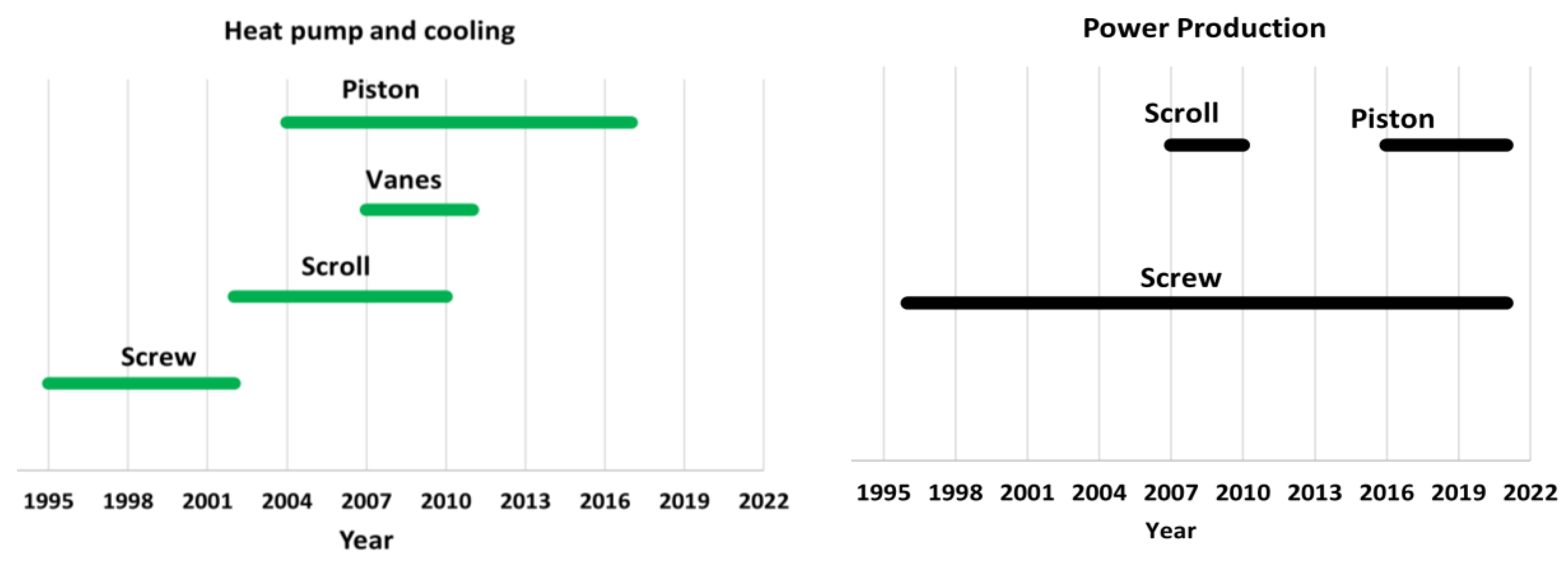
The literature indicated that most studies about two-phase volumetric expanders have been published from 1990 to the present day, thus, covering at least three decades. However, the literature survey suggested that piston, screw, vane, and scroll systems were investigated between 1995 and 2017 for heat pump and cooling applications (Figure 19). Conversely, screw devices appeared to be the most investigated for power production applications between 1996 and 2021, despite some studies involving scroll and piston machines. To the best of our knowledge, no study about vane machines for power production was found. However, we found only a review in the literature that dealt with two-phase volumetric devices, whose main topic concerned the potentialities of several numerical models to analyze the flash expansion in variable volume chambers [22].

8.2. Comparison of the Two-Phase Devices

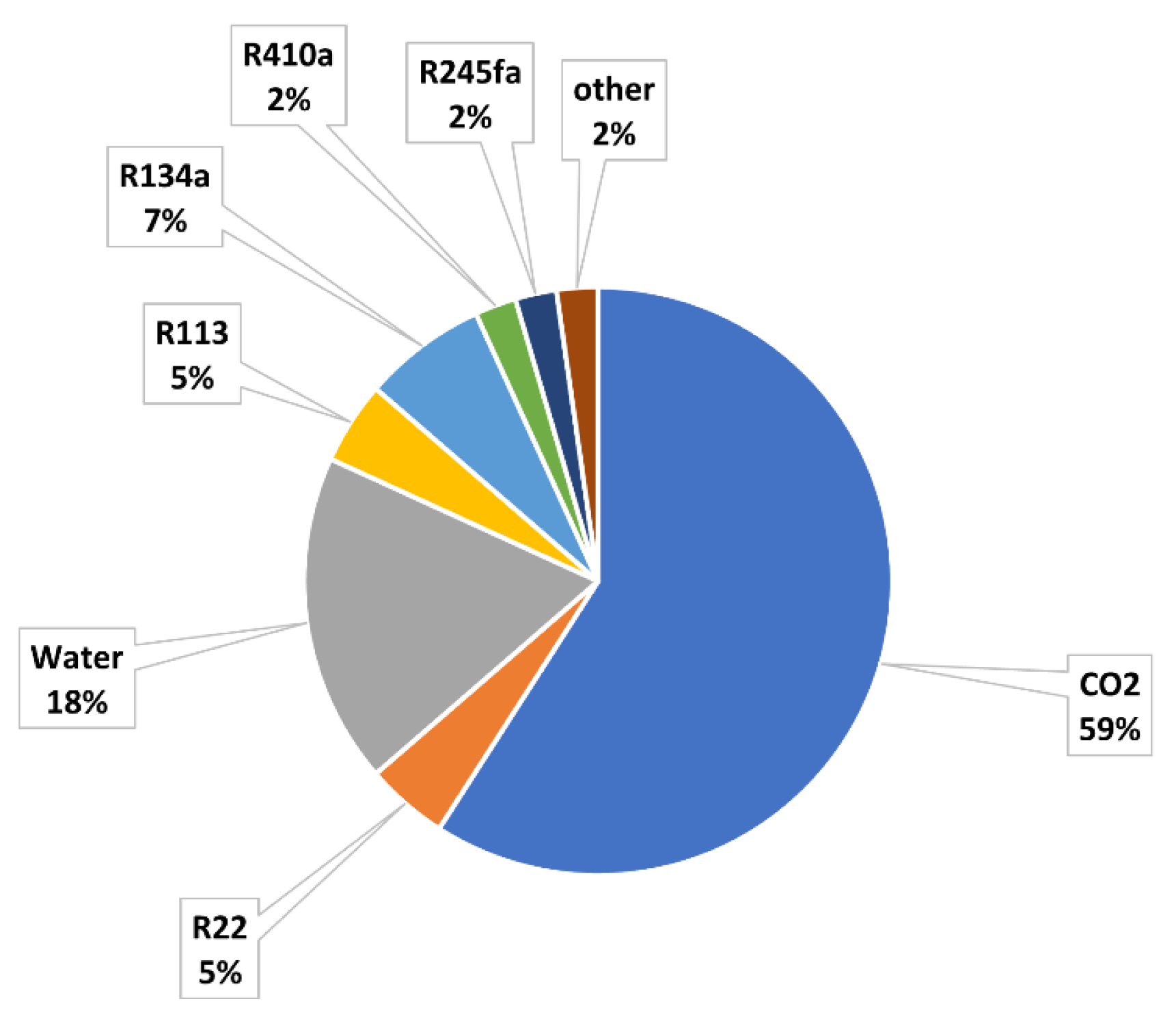
The literature overview allowed for the comparison of the performance of devices in the presence of two-phase flows, as employed in heat pumps, cooling applications, and power production, as summarized in Table 5. Nonetheless, most of the data came from studies about heat pumps and cooling cycles, since they appeared to be a debated topic to employ two-phase expanders. As a result, CO2 seemed to be the working fluid primarily involved in assessing the performance of the devices (Figure 20). However, the literature indicated that other fluids were also employed in these applications, such as R134a, R245fa, and R22. Conversely, water steam was the fluid mostly investigated for power production.
The survey revealed how scroll machines exhibited the highest isentropic efficiency in a restricted range between 0.70–0.80, while the other devices showed values belonging to a broader interval between 0.10–0.70 depending on the working conditions.
Nonetheless, the aim to provide a complete assessment of the devices required a comparison in terms of overall efficiency, since it is also indicative of the mechanical efficiency. As a result, the literature revealed that twin screw machines appeared to be the most promising to handle two-phase fluids with a high liquid fraction in a wide range of operating conditions, as revealed by the highest values of the overall efficiency of between 0.27–0.56 [8]. Scroll systems represented another potential technology to expand a fluid in the two-phase state region, as they can manage a liquid mass fraction higher than 0.9 [8] with an acceptable overall efficiency in the range 0.30–0.60. Vane expanders were extensively tested in heat pumps and cooling applications. They appeared suitable to manage two-phase flows with an overall efficiency between 0.20–0.55, despite their limits, which were the need to reduce leaks and friction. Piston devices seemed to be another suitable candidates for expanding a two-phase fluid, although their overall efficiencies fell in a wide range from 0.10 to 0.60 depending on the considered mechanism. Nonetheless, some authors highlighted that piston reciprocating machines suffered damage to the cylinder surface and rings due to their reduced ability to withstand the droplets that limit lubrication.
A possible cause impacting the behaviour in the wet expansion may be the flash expansion that depends on the pressure and volume variations of the operating chamber and determines the liquid phase agitation and the vapor generation.
The volumetric performances were comparable for all the technologies, although vane devices presented the lowest value, probably due to their higher leaks and pressure losses.
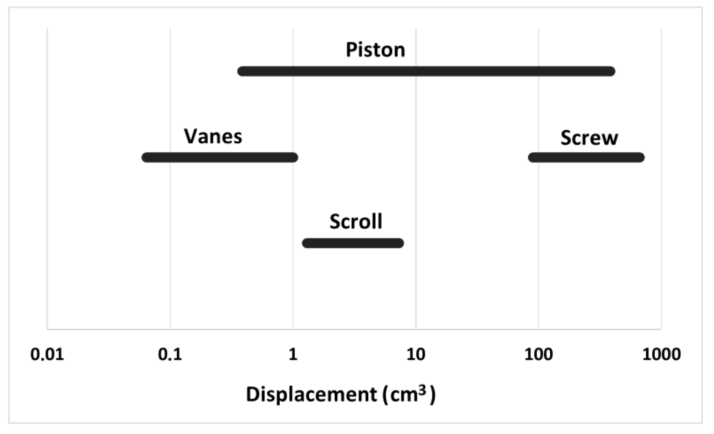
The comparison revealed that the lowest and highest displacement belonged, respectively, to vane devices and screw machines (Figure 21), thus, affecting the mass flow rate processed by the machine.
In the applications, the BVR was of the same order of magnitude (in the range of 2–8) for the scroll, screw, and vane machines, while it increased for pistons (up to 21).
As a result, the use of each expansion device under designed operating conditions appeared feasible for a selected power range (Figure 22). For this reason, screw machines led to the highest output power for heat pumps, refrigeration, and power production. At the same time, piston and vane systems were attractive for small-scale applications because of their lower values of delivered power.
Furthermore, another aspect that should be considered in the choice of a two-phase expander is its complexity that concerns the mechanical architecture and the control of the flow through the ports (see Table 5). The survey suggested that a high mechanical complexity characterized screw and reciprocating piston machines [84]. Nonetheless, different architectures for piston systems provided devices with the lowest complexity, such as rolling, swing, and free expanders [84].

9. Conclusions

This work has provided an overview of the state-of-the-art aspects that characterize volumetric expanders fueled with a pure substance in the two-phase state to fill the gaps in the scientific literature where the contributions appear scarce. As a result, we attempted to identify the critical points that deserve more attention to improve the performances of these systems through numerical and experimental analysis.
The following points summarize the main conclusions drawn from several papers published in the literature in the last thirty years about ORC and heat pump applications in which the expander operates with a two-phase fluid:
-
Flash expansion in a variable chamber volume needs to be further analyzed by numerical and experimental studies because it affects the operation of a two-phase device. In detail, the thermal disequilibrium between the vapor and liquid phases seems crucial because it penalizes the efficiency of the machines. As a result, the two-phase fluid must consist of the vapor phase containing fine liquid particles uniformly dispersed to improve the efficiency of the expander. The literature suggested that this aspect deserves further numerical and experimental investigations;
-
To the best of the authors’ knowledge, two-phase volumetric machines operating with a fixed pressure ratio allow for the changing of their SVFR for the same BVR and timing. As a result, the expansion can be complete or incomplete in the same device for the same pressure ratio, thus, resulting in a different isentropic efficiency. Consequently, some experimental or numerical analysis might be developed to confirm or rebut this conjecture;
-
Improving two-phase volumetric machines requires optimization of the shape of valves and ports to reduce the pressure drop and reduce leaks and friction losses. In detail, the passage of the fluid through the valves causes flashing effects;
-
Scroll and twin-screw expanders exhibit comparable volumetric and isentropic efficiency in which the maximum values of the latter are between 0.7 and 0.8. Scroll devices are employed for a few up to a dozen of kilowatt, while twin screw systems cover higher power output. Nonetheless, twin screw machines seem to be the most suitable for commercial applications because of their better compatibility with the liquid phase;
-
Vane expanders represent other machines tested as two-phase expanders in a power range below 1 kW, but most reach an isentropic efficiency within 0.15–0.62 and exhibit difficulty reducing friction and leaks;
-
Piston machines provide a broader range for isentropic efficiency because they are available in various kinematic architectures that result in different performances. Although some authors suggest that the liquid phase involves some issues in piston expanders, the literature has proposed them as machines suitable for transcritical CO2 vapor compression refrigeration cycles. Reciprocating piston systems exhibit an isentropic efficiency from 0.10–0.70 depending on the operating conditions. This range diminishes for rolling and swinging piston systems whose most of their isentropic efficiencies fall between 0.30 to 0.60. Nonetheless, other studies aim to propose the free piston expander as a two-phase machine suitable for ORC applications because its isentropic efficiency falls between 0.65–0.70, at least in the expansion of single-phase flow. Consequently, an investigation of a free piston machine operating in the two-phase region may be developed to assess the performance of this system.
Future research should elaborate on detailed mathematical models of two-phase volumetric expanders, including the heat transfer phenomena between vapor and liquid phases, which could affect the isentropic efficiency of these machines. Moreover, such mathematical models should be validated by experimental campaigns to evaluate the alignment between the calculated and measured values of the isentropic efficiency.

Author Contributions

Conceptualization, M.F.; methodology, S.B.; data curation, M.F. and S.B.; writing—original draft preparation: M.F. and S.B.; writing—review and editing, M.F., S.B. and M.A.; visualization, M.A. All authors have read and agreed to the published version of the manuscript.

Funding

This research received no external funding.

Institutional Review Board Statement

Not applicable.

Informed Consent Statement

Not applicable.

Data Availability Statement

Not applicable.

Conflicts of Interest

The authors declare no conflict of interest.

Nomenclature

Abbreviations
EExperimental
FFree
NcNumerical
PtPatent
RResearch
REReciprocating
RORolling
RARadial
SSwing
Acronyms
BVRBuilt-in volume ratio [-]
CHPCombined heating and power
FFFilling Factor [-]
HP Heat pump
PPPower production
SVFRSpecific volumetric fluid ratio [-]
Greek symbols
ηEfficiency [-]
Symbols
m ˙ Mass flow rate [kg/s], [kg/h]
NRotating speed [rpm], [rad/s]
pPressure [Pa], [MPa], [bar]
PPower [W], [kW]
TTemperature [°C], [K]
VDisplacement [cm3], [mm3]
Subscripts
inInlet
isIsentropic
mMechanical
ovOverall
volVolumetric

References

  1. Briola, S.; Di Marco, P.; Gabbrielli, R. Two-Phase Fluid Expanders—A Review. In Proceedings of the XXX Heat Transfer Conference of Union Italian Thermo-Fluid Dynamic (UIT), Bologna, Italy, 24–27 June 2012. [Google Scholar]
  2. Briola, S.; Di Marco, P.; Gabbrielli, R. Two-Phase Fluid Compressors—A Review. In Proceedings of the XXXI Heat Transfer Conference of Union Italian Thermo-Fluid Dynamic (UIT), Como, Italy, 25–27 June 2013. [Google Scholar]
  3. Heidelck, R.; Kruse, H. Expansion machines for Carbon Dioxide based on modified reciprocating machines. In Proceedings of the Final Proceedings of the 4th-IIR Gustav-Lorentzen Conference on Natural Working Fluids at Purdue, West Lafayette, IN, USA, 25–28 July 2000. [Google Scholar]
  4. Li, D.; Baek, A.E.; Groll, P.B. Thermodynamic analysis of vortex tube and work out expansion devices for the transcritical carbon dioxide cycle. In Proceedings of the Final Proceedings of the 4th-IIR Gustav-Lorentzen Conference on Natural Working Fluids at Purdue, West Lafayette, IN, USA, 25–28 July 2000. [Google Scholar]
  5. Heyl, P.; Quack, H. Transcritical CO2 cycle with expander/compressor. In Proceedings of the Final Proceedings of the 4th-IIR Gustav-Lorentzen Conference on Natural Working Fluids at Purdue, West Lafayette, IN, USA, 25–28 July 2000. [Google Scholar]
  6. Kruse, H.; Rüssmann, H.; Martin, E.; Jakobs, R. Positive Displacement Carbon Dioxide Expansion Machines-Changes and Limitations. In Proceedings of the International Compressor Engineering Conference, West Lafayette, IN, USA, 17–20 July 2006; p. 1766. [Google Scholar]
  7. Zhang, Z.; Ma, Y.; Li, M.; Zhao, L. Recent advances of energy recovery expanders in the transcritical CO2 refrigeration cycle. HVACR Res. 2013, 19, 376–384. [Google Scholar]
  8. Dumont, O.; Parthoens, A.; Dickes, R.; Lemort, V. Experimental investigation and optimal performance assessment of four volumetric expanders (scroll, screw, piston and roots) tested in a small-scale organic Rankine cycle system. Energy 2018, 165, 1119–1127. [Google Scholar] [CrossRef] [Green Version]
  9. Daniarta, S.; Kolasinski, P. A preliminary study of two phase volumetric expanders and their application in ORC systems. In Proceedings of the 6th International Seminar on ORC Power Systems, Munich, Germany, 11–13 October 2021. [Google Scholar]
  10. Lemort, V.; Legros, A. Positive displacement expanders for Organic Rankine Cycle systems. In Organic Rankine Cycle (ORC) Power Systems; Elsevier: Amsterdam, The Netherlands, 2017. [Google Scholar]
  11. Emhardt, S.; Tian, G.; Chew, J. A review of scroll expander geometries and their performances. Appl. Therm. Eng. 2018, 141, 1020–1034. [Google Scholar] [CrossRef]
  12. Imran, M.; Usman, M.; Park, B.S.; Lee, D.H. Volumetric expanders for low grade andwaste heat recovery applications. Renew. Sustain. Energy Rev. 2016, 57, 1090–1109. [Google Scholar] [CrossRef]
  13. Antonelli, M.; Baccioli, A.; Francesconi, M.; Desideri, U.; Martorano, L. Operating maps of a rotary engine used as an expander for micro-generation with various working fluids. Appl. Energy 2014, 113, 742–750. [Google Scholar] [CrossRef]
  14. Antonelli, M.; Baccioli, A.; Francesconi, M.; Martorano, L. Experimental and numerical analysis of the valve timing effects on the performances of a small volumetric rotary expansion machine. Energy Procedia 2014, 45, 1077–1086. [Google Scholar] [CrossRef]
  15. Francesconi, M.; Dori, E.; Antonelli, M. Analysis of Balje diagrams for a Wankel expander prototype. Appl. Energy 2019, 238, 775–785. [Google Scholar] [CrossRef]
  16. Antonelli, M.; Baccioli, A.; Francesconi, M.; Martorano, L. Numerical and experimental analysis of the intake and exhaust valves of a rotary expansion machine for micro generation. Energy Procedia 2015, 81, 461–471. [Google Scholar] [CrossRef]
  17. Francesconi, M.; Pasini, G.; Sani, L.; Antonelli, M. Experimental investigation of a commercial screw compressor as an expander with compressed air. In Proceedings of the 5th International Seminar on ORC Power Systems, Athens, Greece, 9–11 September 2019. [Google Scholar]
  18. Quoilin, S.; Van Den Broek, M.; Declaye, S.; Dewallef, P.; Lemort, V. Techno-economic survey of Organic Rankine Cycle (ORC) systems. Renew. Sustain. Energy Rev. 2013, 22, 168–186. [Google Scholar] [CrossRef] [Green Version]
  19. Richter, L.; Rendlova, Z.; Planicka, S.; Seeger, J.; Taschek, M.; Volf, M.; Pelikan, M.; Linhart, V. Experimental and numerical analysis of an oil-flooded air screw expander. In Proceedings of the 20th Conference on Power System Engineering, Pilsen, Czech Republic, 7–9 September 2021; MATEC Web Conf.. Volume 345. [Google Scholar]
  20. Kanno, H.; Shikazono, N. Experimental and modeling study on adiabatic two-phase expansion in a cylinder. Int. J. Heat Mass Transf. 2015, 86, 755–763. [Google Scholar] [CrossRef] [Green Version]
  21. Lecompte, S.; Van der Broek, M.; De Paepe, M. Initial Design of an Optical-Access Piston Expansion Chamber for Wet-Expansion. Energy Procedia 2017, 129, 307–314. [Google Scholar] [CrossRef]
  22. Van Heule, X.; De Paepe, M.; Lecompte, S. Two-phase volumetric expanders: A review of the state-of-art. Energies 2022, 15, 4991. [Google Scholar] [CrossRef]
  23. Wang, Q.; Wu, W.; He, Z.; Ziviani, D. Analysis of the intake process and its influence on the performance of a two-phase reciprocating expander. Appl. Therm. Eng. 2019, 160, 113943. [Google Scholar] [CrossRef]
  24. Smith, I.K.; Stosic, N.; Kovacevic, A. Power Recovery from Low Grade Heat by Means of Screw Expanders; Elsevier: Amsterdam, The Netherlands, 2014. [Google Scholar]
  25. Smith, K. Development of the trilateral flash cycle system—Part 1: Fundamental aspects. Proc. Inst. Mech. Eng. Part A J. Power Energy 1993, 208, 179–194. [Google Scholar] [CrossRef]
  26. Meng, D.; Liu, Q.; Ji, Z. Effects of two-phase expander on the thermoeconomics of organics double-flash cycles for geothermal power generation. Energy Part D 2022, 239, 122346. [Google Scholar] [CrossRef]
  27. Briola, S.; Di Marco, P.; Gabbrielli, R. Thermodynamic sensitivity analysis of a novel trigeneration thermodynamic cycle with two-phase expanders and two-phase compressors. Energy 2017, 127, 335–350. [Google Scholar] [CrossRef]
  28. Briola, S.; Gabbrielli, R.; Fino, A.; Bischi, A.; Di Marco, P. Working fluid selection and extensive sensitivity analysis for the thermodynamic optimization of a novel trigeneration thermodynamic cycle with two-phase expanders and compressors. Energy 2019, 179, 709–726. [Google Scholar] [CrossRef]
  29. Briola, S.; Gabbrielli, R.; Baccioli, A.; Fino, A.; Bischi, A. Thermo-economic analysis of a novel trigeneration cycle enabled by two-phase machines. Energy 2021, 227, 120453. [Google Scholar] [CrossRef]
  30. Tamura, I.; Taniguchi, H.; Sasaki, H.; Yoshida, R.; Sekiguchi, I.; Yokogawa, M. An analytical investigation of high-temperature heat pump system with screw compressor and screw expander for power recovery. Energy Convers. Manag. 1997, 38, 10–13. [Google Scholar] [CrossRef]
  31. Weitzer, M.; Muller, D.; Karl, J. Two-phase expansion processes in heat pump—ORC systems (Carnot batteries) with volumetric machines for enhanced off-design efficiency. Renew. Energy 2022, 199, 720–732. [Google Scholar] [CrossRef]
  32. Daniarta, S.; Kolasinski, P.; Imre, A.R. A Preliminary design and modeling analysis of two-phase volumetric expanders for a novel reversible Organic Rankine-Based Cycle for Carnot battery technology. Appl. Sci. 2022, 12, 3557. [Google Scholar] [CrossRef]
  33. Fukuta, M.; Yanagisawa, T.; Kosuda, O.; Ogi, Y. Performance of scroll expander for CO2 refrigeration cycle. In Proceedings of the International Compressor Engineering Conference, West Lafayette, IN, USA, 17–20 July 2006. [Google Scholar]
  34. Hiwata, A.; Ikeda, A.; Morimoto, T.; Kosuda, O.; Matsui, M. Axial and radial force control for CO2 scroll expander. In Proceedings of the International Compressor Engineering Conference, West Lafayette, IN, USA, 14–17 July 2008. [Google Scholar]
  35. Kohsokabe, H.; Koyama, M.; Tojo, K.; Matsunaga, M.; Nakayama, S. Performance characteristics of scroll expander for CO2 refrigeration cycles. In Proceedings of the International Compressor Engineering Conference, West Lafayette, IN, USA, 14–17 July 2008. [Google Scholar]
  36. Huff, H.J.; Radermacher, R. CO2 Compressor-Expander Analysis; Report prepared for Air-conditioning and Refrigeration Technology Institute, Under ARTI 21-CR Program Contract Number 611-10060; Air-Conditioning and Refrigeration Technology Institute: Arlington, VA, USA, 2003. [Google Scholar]
  37. Huff, H.J.; Lindsay, D.; Radermacher, R. Positive displacement compressor and expander simulation. In Proceedings of the International Compressor Engineering Conference, West Lafayette, IN, USA, 16–19 July 2002. [Google Scholar]
  38. Westphalen, D.; Dieckmann, J. Scroll expander for carbon dioxide air conditioning cycles. In Proceedings of the International Compressor Engineering Conference, West Lafayette, IN, USA, 12–15 July 2004. [Google Scholar]
  39. Westphalen, D.; Dieckmann, J. Scroll expander for carbon dioxide cycle. In Proceedings of the International Compressor Engineering Conference, West Lafayette, IN, USA, 17–20 July 2006. [Google Scholar]
  40. Kohsokabe, H.; Funakoshi, F.; Tojo, K.; Nakayama, S.; Kohno, K.; Kurashige, K. Operating characteristics of CO2 chiller cycles with expander-compressor unit. In Proceedings of the 8th IIR Gustav Lorentzen Conference on Natural Working Fluids, Copenhagen, Denmark, 7–10 September 2008. [Google Scholar]
  41. Kim, H.J.; Ahn, J.M.; Cho, S.O.; Cho, K.R. Numerical simulation on scroll expander–compressor unit for CO2 transcritical cycles. Appl. Therm. Eng. 2008, 28, 1654–1661. [Google Scholar] [CrossRef] [Green Version]
  42. Nagata, H.; Kakuda, M.; Sekiya, S.; Shimoji, M.; Koda, T. Development of a scroll expander for the CO2 refrigeration cycle. In Proceedings of the International Compressor Engineering Conference, West Lafayette, IN, USA, 12–15 July 2010. [Google Scholar]
  43. Kim, H.J.; Ahn, J.M.; Park, I.; Rha, P.C. Scroll expander for power generation from a low-grade steam source. Proc. IMechE Part A J. Power Energy 2007, 221, 705–711. [Google Scholar] [CrossRef]
  44. Mayer, K. Research, Development and Demonstration of Micro-CHP System for Residential Applications; DOE/NT/42216; ECR Int.: Utica, NY, USA, 2010. [Google Scholar]
  45. Muhammad, I.; Muhammad, U. Positive Displacement Machines—Modern Design Innovations and Tools, Chapter 11—Mathematical Modelling for Positive Dis-Placement Expanders; Elsevier: Amsterdam, The Netherlands, 2019. [Google Scholar]
  46. Smith, I.K.; Stosic, N.; Kovacevic, A. Power Recovery from Low Cost Two-Phase Expanders; Geothermal Research Council: San Diego, CA, USA, 2001. [Google Scholar]
  47. Sprankle, R.S. Electrical Power Generating Systems. U.S. Patent 3,751,673, 7 August 1973. [Google Scholar]
  48. Smith, I.K.; Stosic, N. Development of the Trilateral Flash Cycle System Part 3: The design of high efficiency two phase screw expanders. Proc. Inst. Mech. Eng. Part A J. Power Energy 1996, 210, 75–93. [Google Scholar] [CrossRef]
  49. Smith, I.K.; Stosic, N. Screw expanders increase output and decrease the cost of geothermal binary power plant systems. In Proceedings of the Geothermal Research Council Annual Meeting, Reno, NV, USA, 25–28 September 2005. [Google Scholar]
  50. Smith, I.K.; Stosic, N.; Kovacevic, A. Cost effective small scale ORC systems for power recovery from low enthalpy resources. In Proceedings of the Geothermal Research Council Annual Meeting, Reno, NV, USA, 30 September–3 October 2007. [Google Scholar]
  51. Read, M.; Stosic, N.; Smith, I.K. Optimization of screw expanders for power recovery from low-grade heat sources. Energy Technol. Policy 2014, 1, 131–142. [Google Scholar] [CrossRef]
  52. Vasuthevan, H.; Brummer, A. Thermodynamic modelling of screw expander in a Trilateral Flash cycle. In Proceedings of the International Compressor Engineering Conference, West Lafayette, IN, USA, 11–14 July 2016. [Google Scholar]
  53. Nikolov, A.; Brummer, A. Impact of different clearance heights on the operation of a water-flooded twin-screw expander—Experimental investigations based on indicator diagrams. IOP Conf. Ser. Mater. Sci. Eng. 2018, 425, 12008. [Google Scholar] [CrossRef]
  54. Bianchi, G.; Marchionni, M.; Miller, J.; Tassou, S.A. Modelling and off-design performance optimisation of a trilateral flash cycle system using two-phase twin-screw expanders with variable built-in volume ratio. Appl. Therm. Eng. 2020, 179, 115671. [Google Scholar] [CrossRef]
  55. Smith, I.K.; Stosic, N.; Aldis, C.A.; Kovacevic, A. Twin screw two-phase expanders in large chiller units. In Proceedings of the IMechE, International Conference on Compressors and Their Systems, London, UK, 30 September 1999. [Google Scholar]
  56. Smith, I.K.; Stosic, N. The expressor: An efficiency boost to vapour compression systems by power recovery from the throttling process. In Proceedings of the ASME International Mechanical Engineering Congress and Exposition, San Francisco, CA, USA, 12–17 November 1995. [Google Scholar]
  57. Brasz, J.J.; Shitsla, V.; Stosic, N.; Smith, I.K. Development of a twin-screw expressor as a throttle valve replacement for water-cooled chillers. In Proceedings of the International Compressor Engineering Conference, West Lafayette, IN, USA, 25–28 July 2000. [Google Scholar]
  58. Stosic, N.; Smith, I.K.; Kovacevic, A. A twin screw combined compressor and expander for CO2 refrigeration systems. In Proceedings of the International Compressor Engineering Conference, West Lafayette, IN, USA, 16–19 July 2002. [Google Scholar]
  59. Vodicka, V.; Novotny, V.; Mascuch, J.; Kolovratnik, M. Impact of major leakages on characteristics of a rotary vane expander for ORC. Energy Procedia 2017, 129, 387–394. [Google Scholar] [CrossRef]
  60. Yang, B.; Sun, S.; Peng, X.; Guo, B.; Xing, Z. Modeling and experimental investigation on the internal leakage in a CO2 rotary vane expander. In Proceedings of the International Compressor Engineering Conference, West Lafayette, IN, USA, 14–17 July 2008. [Google Scholar]
  61. Yang, B.; Peng, X.; Sun, S.; Guo, B.; Xing, Z. Study of a rotary vane expander for the transcritical CO2 cycle—Part I: Experimental investigation. HVACR Res. 2009, 15, 4. [Google Scholar] [CrossRef]
  62. Yang, B.; Peng, X.; He, Z.; Guo, B.; Xing, Z. Experimental investigation on the internal working process of a CO2 rotary vane expander. Appl. Therm. Eng. 2009, 29, 2289–2296. [Google Scholar] [CrossRef]
  63. Yang, B.; Peng, X.; Sun, S.; Guo, B.; Xing, Z. A study of the vane dynamics in a rotary vane expander for the transcritical CO2 refrigeration cycle. Proc. Inst. Mech. Eng. Part A J. Power Energy 2009, 223, 429–440. [Google Scholar] [CrossRef]
  64. Fukuta, M.; Higasiyama, M.; Yanagisawa, T.; Ogi, Y. Observation of CO2 transcritical expansion process. In Proceedings of the International Compressor Engineering Conference, West Lafayette, IN, USA, 14–17 July 2008. [Google Scholar]
  65. Jia, X.; Zhang, B.; Pu, L.; Guo, B.; Peng, X. Improved rotary vane expander for transcritical CO2 cycle by introducing high-pressure gas into the vane slots. Int. J. Refrig. 2011, 34, 732–741. [Google Scholar] [CrossRef]
  66. Mahmoud, A.M.; Sherif, S.A.; Lear, W.E. Analysis of rotary-vane two-phase refrigeration expanders: Geometric and thermodynamic modeling. In Proceedings of the 45th Aerospace Sciences Meeting and Exhibit, Reno, NV, USA, 8–11 January 2007. [Google Scholar]
  67. Mahmoud, A.M.; Sherif, S.A.; Lear, W.E. Development and testing of a rotary-vane two-phase refrigerating expander. In Proceedings of the ASME 2009 International Mechanical Engineering Congress & Exposition, Lake Buena Vista, FL, USA, 13–19 November 2009. [Google Scholar]
  68. Wang, M.; Zhao, Y.; Cao, F.; Bu, G.; Wang, Z. Simulation study on a novel vane-type expander with internal two-stage expansion process for R-410A refrigeration system. Int. J. Refrig. 2012, 35, 757–771. [Google Scholar] [CrossRef]
  69. Kim, H.J.; Kim, W.Y.; Ahn, J.M.; Cho, S.O. Numerical study on the performance improvement of a rotary vane expander for a CO2 heat pump cycle. Int. J. Air-Cond. Refrig. 2011, 19, 311–319. [Google Scholar] [CrossRef]
  70. Burugupally, S.P.; Weiss, L. Design and performance of a miniature free piston expander. Energy 2019, 170, 611–618. [Google Scholar] [CrossRef]
  71. Li, G.; Zhanh, H.; Yang, F.; Song, S.; Chang, Y.; Yu, F.; Wang, J.; Yao, B. Preliminary Development of a Free Piston Expander-Linear Generator for Small-Scale Organic Rankine Cycle (ORC) Waste Heat Recovery System. Energies 2016, 9, 300. [Google Scholar] [CrossRef]
  72. Li, M.; Ma, Y.; Guan, H.; Li, L. Development and Experimental Study of CO2 Expander in CO2 Supercritical Refrigeration Cycles. Int. J. Green Energy 2004, 1, 88–99. [Google Scholar] [CrossRef]
  73. Nickl, J.; Will, G.; Quack, H.; Kraus, W.E. Integration of a three stage expander into a CO2 refrigeration system. Int. J. Refrig. 2005, 28, 1219–1224. [Google Scholar] [CrossRef]
  74. Baek, J.S.; Groll, E.A.; Lawless, P.B. Piston-cylinder work producing expansion machine in a transcritical carbon dioxide cycle. Part I: Experimental investigation. Int. J. Refrig. 2005, 28, 141–151. [Google Scholar] [CrossRef]
  75. Baek, J.S.; Groll, E.A.; Lawless, P.B. Piston-cylinder work producing expansion machine in a transcritical carbon dioxide cycle. Part II: Theoretical model. Int. J. Refrig. 2005, 28, 141–151. [Google Scholar] [CrossRef]
  76. Yang, J.; Zhang, L.; Shi, J.Y. Development and Performance Analysis of a Two Cylinder Rolling Piston Expander for Transcritical CO2 System; Purdue ePubs; Purdue University: West Lafayette, IN, USA, 2006. [Google Scholar]
  77. Li, M.; Ma, Y.; Tian, H. A rolling piston-type two phase expander in the transcritical CO2 cycle. HVACR Res. 2009, 15, 729–741. [Google Scholar] [CrossRef]
  78. Tian, H.; Ma, Y.; Li, M.; Wang, W. Study on expansion recovery in CO2 trans-critical cycle. Energy Convers. Manag. 2010, 51, 2516–2522. [Google Scholar] [CrossRef]
  79. Rijpkema, J.; Thantla, S.; Fridh, J.; Andersson, S.; Munch, K. Experimental investigation and modeling of a reciprocating piston expander for waste heat recovery from a truck engine. Appl. Therm. Eng. 2021, 186, 116425. [Google Scholar] [CrossRef]
  80. Available online: https://www.greencarcongress.com/2015/06/20150618-libertine.html (accessed on 22 May 2022).
  81. Available online: https://www.libertine.co.uk/libertine-brunel-reach-milestone-free-piston-orc-demonstration-project/ (accessed on 22 May 2022).
  82. Guan, H.; Ma, Y.; Li, M. Some design features of CO2 swing piston expander. Appl. Therm. Eng. 2006, 26, 237–243. [Google Scholar]
  83. Sakitani, K.; Moriwaki, M.; Okamoto, M.; Kumakura, E.; Okamoto, T. Development of two-phase flow expander for CO2 heat pumps and air-conditioners. In Proceedings of the 2008 Short Course on 12th International Refrigeration and Air-Conditioning Conference at Purdue, West Lafayette, IN, USA, 14–17 July 2008. [Google Scholar]
  84. Matsui, M.; Wada, M.; Ogata, T.; Hasegawa, H. Development of High Efficiency Technology of Two Stage Rotary Expander for CO2 Refrigerant; Purdue ePubs; Purdue University: West Lafayette, IN, USA, 2008. [Google Scholar]
  85. Fukuta, M.; Anzai, F.; Motozawa, M.; Terawaki, H.; Yanagisawa, T. Performance of radial piston type reciprocating expander for CO2 refrigeration cycle. Int. J. Refrig. 2014, 42, 48–56. [Google Scholar] [CrossRef]
  86. Galoppi, G.; Secchi, R.; Ferrari, L.; Ferrara, G.; Karellas, S.; Fiaschi, D. Radial piston expander as a throttling valve in a heat pump: Focus on the 2-phase expansion. Int. J. Refrig. 2017, 82, 237–282. [Google Scholar] [CrossRef]
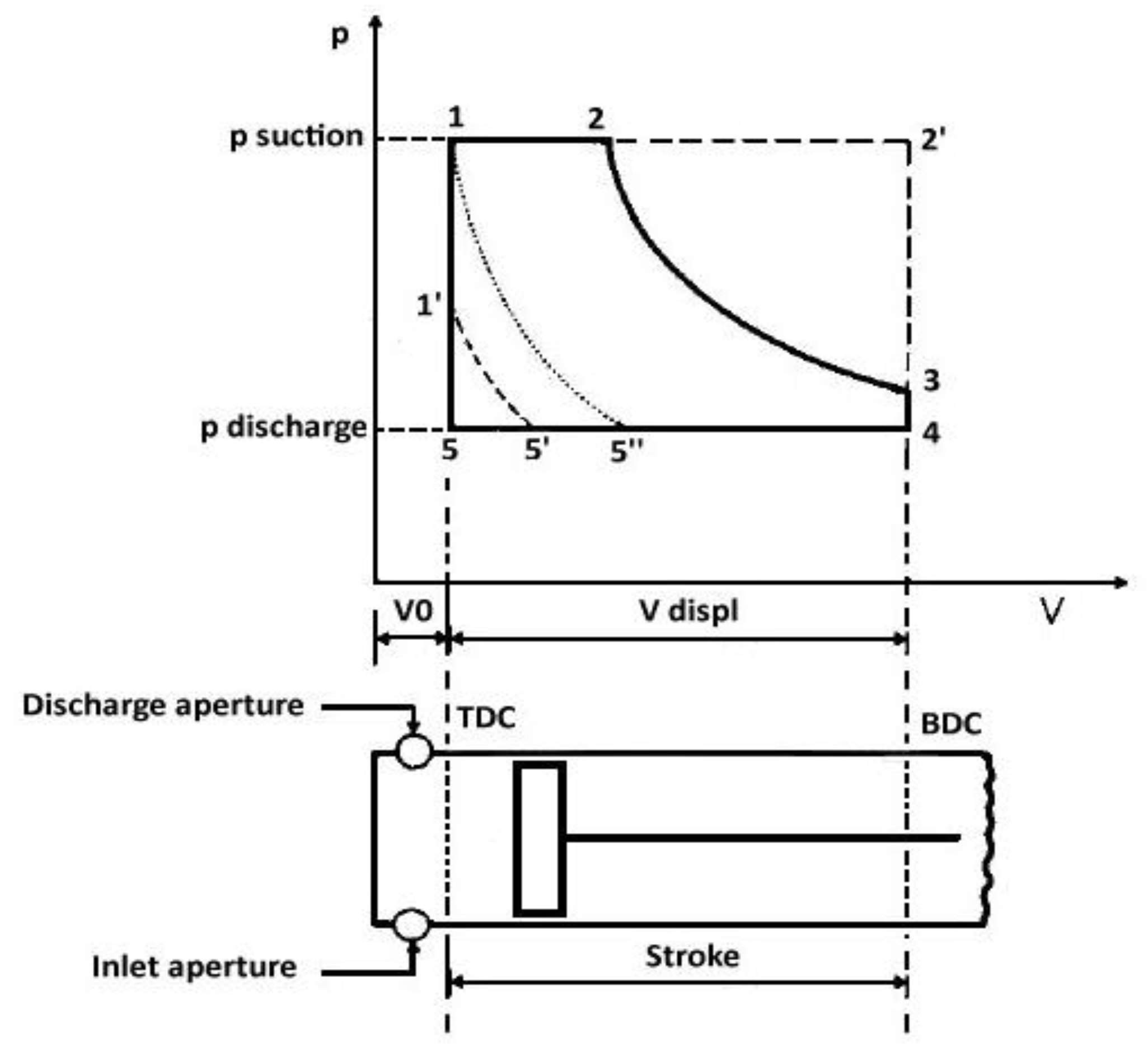
Figure 1. Pressure–volume diagram of a piston expander.
Applsci 12 10328 g001
Figure 2. Under-expansion (left) and over-expansion (right).
Applsci 12 10328 g002
Figure 3. Expansion process on the right and left hand side of the critical point performed by a volumetric machine (reprinted from [6]): thermodynamic diagram (a), indicated cycle for the line B (b), indicated cycle for the line C (c), and indicated cycle for the line D (d) with the sharp pressure drop due to the presence of a liquid (in the dashed circle).
Applsci 12 10328 g003aApplsci 12 10328 g003b
Figure 4. T–s diagram of vapor compression refrigeration cycle. Here, 3–4a is the throttling valve, and 3–4b is the two-phase expander.
Applsci 12 10328 g004
Figure 5. T–s diagram of transcritical vapor compression refrigeration cycle.
Applsci 12 10328 g005
Figure 6. T–s diagram of the trilateral flash cycle [25].
Applsci 12 10328 g006
Figure 7. T–s diagram of Smith cycle [24].
Applsci 12 10328 g007
Figure 8. T–s diagram of organic double-flash cycle [26].
Applsci 12 10328 g008
Figure 9. T–s diagram of a traditional ORC (1-2-3-3’-4) and wet vapor ORC (1-2’-3’-4) [24].
Applsci 12 10328 g009
Figure 10. T–s diagram of innovative CCHP cycle enabled by two-phase machines [29].
Applsci 12 10328 g010
Figure 11. High-temperature heat pump [30].
Applsci 12 10328 g011
Figure 12. Two-phase scroll expander, with geometry (a) [12] and principle of operation (b) [10].
Applsci 12 10328 g012
Figure 13. Two-phase twin screw expander, with architecture (a) [12] and principle of operation (b) [45].
Applsci 12 10328 g013
Figure 14. Two-phase vane expander, with principle of operation (a) [12] and leakage pathways (b) [59].
Applsci 12 10328 g014
Figure 15. Two-phase reciprocating piston expander, with the principle of operation for an axial device (a) and a radial one (b) [45].
Applsci 12 10328 g015
Figure 16. Principle of operation of a rolling (left) and swing (right) piston expander.
Applsci 12 10328 g016
Figure 17. Two-phase free piston expander, showing the principle of operation [71].
Applsci 12 10328 g017
Figure 18. Results from the literature analysis, showing an investigation of the expander technologies (a) and of their applications (b).
Applsci 12 10328 g018
Figure 19. Timeline of the research about two-phase volumetric expanders.
Applsci 12 10328 g019
Figure 20. Percentage distribution of the fluids employed in the selected studies.
Applsci 12 10328 g020
Figure 21. Distribution of the displacement values for the analyzed expanders.
Applsci 12 10328 g021
Figure 22. Power output for different expansion devices under two-phase conditions, showing heat pump and cooling (left), and power production (right).
Applsci 12 10328 g022
Table 1. Experimental and numerical results related to two-phase scroll expanders.
Article,
Year
StudyUseFluidV
[cm3]
BVR
[-]
pin
[MPa]
Tin
[°C]
pout
[MPa]
N
[rpm]
m ˙ [kg/h] P
[W]
ηis
[-]
ηm
[-]
ηov
[-]
ηvol
[-]
[33]
2006
Nc, EHPCO23.352.1894042000–4000 0.30–0.600.80
[35]
2008
EHPCO22.82.08.2363.96–4.772200–3400130–225 0.70 0.70–0.90
[36]
2003
NcHPR22,
CO2
7.32.428.56 4.171500–3300 0.73–0.36 0.50–0.88
[37]
2002
NcHP
[38]
2004
NcHPCO21.82.513157.2 3500340 0.60
[39]
2004
EHPCO22.32124 4.133001820.637
[40]
2008
EHPCO2 2500–3000
[41]
2007
NcHPCO21.322.918.5–1120–403.0–4.535000.0630.4400.8610.600–0.6500.5440.850–0.900
[42]
2010
EHPCO2 1800–3600280–510 0.97–1.54
[43]
2007
Nc, EPPWater 1.20–1.30139–1450.111000–140030010–12 E
12–15 N
0.340.42–0.52
[44]
2010
ECHPWater 2800–3600 1.9–2.5
Table 2. Experimental and numerical results related to two-phase screw expanders.
Article,
Year
StudyUseFluidV
[cm3]
BVR
[-]
pin
[MPa]
Tin
[°C]
pout
[MPa]
N
[rpm]
m ˙ [kg/s]P
[kW]
ηis
[-]
ηad
[-]
ηvol
[-]
[47]
1973
PtPPWater
[48]
1996
Nc, EPPR113
n butane
3–6 90–120 3600–4800 10–50 0.20–0.80
[49]
2005
NcPPR134a
n butane
3000 879–2300 0.75–0.80
[50]
2007
EPPR124 22 0.74
[51]
2014
Nc, EPPWater 45000.2–1.170–140 0.30–0.75
[52]
2016
NcPP 6644.10.68–1.10160–180 0.8–1.4 0.10–0.70
[53]
2018
EPPWater902.50.3–0.5600.118,0000.02–0.12
[54]
2020
NcPPR245fa 2.63–5.060.64 0.113000–600024.854.2–92.7 0.63–0.820.53–0.77
[55]
1997
NcHPNH3
Steam
[56]
1999
EHPR113 2.850.8451260.371500–3800 6–15 0.50–0.76
[57]
1995
NcHPR134a 4200 75
[58]
2000
EHPR113 1.85–1.85 1500–30001–1.510–20 0.70
[59]
2002
HPCO2 10403.48
Table 3. Experimental and numerical results related to two-phase vane expanders.
Article,
Year
StudyUseFluidV
[cm3]
BVR
[-]
pin
[MPa]
Tin
[°C]
pout
[MPa]
N
[rpm]
m ˙ [kg/h] P
[kW]
ηis
[-]
ηm
[-]
ηov
[-]
ηvol
[-]
[60]
2009
EHPCO2 7.85–8.35 4.51–4.94800–1800658–6730.348–0.3790.19–0.23 0.17–0.30
[61]
2008
Nc, EHP 2.1 500–3000 0.10–0.60
[62]
2009
EHPCO2 7.5–9.032.4–44.34.8–6.4400–1400 0.17–0.28 0.17–0.30
[63]
2009
EHPCO2
[64]
2008
EHPCO20.0642.09.135–454.11000–2500 0.8–0.90.50.6–0.7
[65]
2011
EHPCO2 7.91–8.9834–423.78–4.08800–1900660.5–719.00.78–0.980.15–0.45 0.22–0.35
[66]
2007
NcHPCO21–3 1.729 0.584 0.85
[67]
2009
EHPR22
R134a
5.0–7.5
[68]
2010
NcHPR410a 3.3954.41.0800–3000331.20.4–0.60.36–0.620.47–0.88 0.37–0.76
[69]
2011
NcHPCO21.69 9.0354.53000 0.138–0.312 0.198–0.4270.487–0.775
Table 5. Summary of the performances of two-phase volumetric expanders.
TypeTolerance to Wet ExpansionPinTinN m ˙ PηisηadηmηovηvolMechanical Complexity
[bar][°C][rpm][kg/s][kW][-][-][-][-][-]
ScrollMedium8–13120–1451000–40001.8 × 10−5–0.140.4–120.70–0.80 0.60–0.650.30–0.600.42–0.80Medium
ScrewHigh3–10040–1801500–48000.02–24.806–23000.10–0.700.20–0.80 0.27–0.560.53–0.77Medium–high
VanesMedium21–9132–54500–30000.092–0.2000.138–0.9800.15–0.62 0.47–0.900.20–0.500.22–0.78Medium
PistonMedium–low12–10033–120500–30000.001–30.1–0.80.20–0.70 0.50–0.900.10–0.600.50–0.80Low–high
Publisher’s Note: MDPI stays neutral with regard to jurisdictional claims in published maps and institutional affiliations.