Article

Asymmetric Constrained Control of a Cervical Orthotic Device Based on Barrier Sliding Modes

1
Centro de Innovación y Desarrollo Tecnológico en Cómputo, Instituto Politécnico Nacional, Mexico City 07700, Mexico
2
Medical Robotics and Biosignal Processing Laboratory, Unidad Profesional Interdisciplinaria de Biotecnología, Instituto Politécnico Nacional, Mexico City 07340, Mexico
*
Author to whom correspondence should be addressed.
Current address: Department of Biomedical Data Science, Standford University, Stanford, CA 94305, USA.
Appl. Sci. 2022, 12(20), 10286; https://doi.org/10.3390/app122010286
Submission received: 27 August 2022 / Revised: 27 September 2022 / Accepted: 4 October 2022 / Published: 13 October 2022
(This article belongs to the Section Robotics and Automation)

Abstract

:
This work proposes a robust sliding mode controller to enforce the tracking trajectory of a cervical orthotic device subjected to asymmetric box constraints. The convergence analysis employs an asymmetric barrier Lyapunov function (ABLF), whose argument is a restricted sliding surface. The stability analysis demonstrates the finite-time convergence of the states towards the sliding surface and, therefore, the exponential stability of the system trajectories. The controller ensures the fulfillment of the restrictions imposed on the sliding surface and consequently over the states. Numerical simulations exhibit the performance of the proposed controller ensuring restricted movements for flexion and extension of a virtual orthotic cervical device. The restricted movements obey asymmetric constraints according to the therapies proposed by medical specialists.

1. Introduction

1.1. Preliminaries

Currently, emerging technologies provide feasible solutions for medical problems [1]. In terms of physical medicine and rehabilitation, the improvement of classical static orthosis and prosthesis has helped patients to recover their functional abilities in a shorter period of time [2]. Static orthosis usually immobilizes or restricts the motion of human limbs. They are made with diverse materials depending on their applications [3]. On the other hand, an active orthosis is a device that increases the ability of a person suffering from pathology or a fracture augmenting the power at one or more joints of the extremities by means of a mechanical actuated structure [4]. Depending on the physical affectation, the specialists should suggest the kind of orthosis to use. Cervical orthoses are a particular case of these devices which are designed to control head movement and neck function, cervical orthoses vary greatly in the degree to which they immobilize the neck and unload head weight [5,6].
The most common cervical orthoses applications include the physiotherapy of head pain such as migraines [7], correction of spinal deformities, rehabilitation in postoperative procedures [8], whiplash-associated disorders, and non-operative treatment for fractures [9,10]. Some examples are the halo vest, Philadelphia collars, Minerva collars, aspen, stiff-neck Miami collar, among others [3,11]. Even though, several studies support the effectiveness of these orthoses immobilizing the fracture sites [10], current studies have demonstrated the advantages of using active orthoses, not only in cervical injuries but also in lower-limb rehabilitation [12]. The design of a cervical orthosis must satisfy the support, prevention, and correction of cervical injuries in patients [3]. Moreover, it must satisfy three-point pressure in parts of the body where nerves and tissues are not affected by the structure system [13]; the manufacturing of cervical orthosis devices should be circumferential for supporting the neck and limiting the range of motion. In addition, the manufacturing device needs to be elaborated with material that does not irritate the skin. Indeed, some researchers evaluated different types of orthosis that have effects on the quality of treatment depending if the injury is a fracture, postoperative treatment, or deformity [14]. The main parameters to be evaluated in the design of an orthosis are the restricted motion, the correct size, comfort assessment control of snaking, and control of flexion/extension/rotation [8,10]. Some evaluations compare the efficiency of common cervical orthosis finding the main complications of wearing those devices [10]. The main issues related to wearing a cervical orthosis are infections, pressure in plastic vests, injuries in nerves, occipital ulceration, stiffness of facial muscles, and control motion [8,15].
Robotic cervical orthoses have to ensure a correct control range of motion during rehabilitation for either postoperative surgeries, fractures, or cervical injuries during rehabilitation sessions [16,17]. Some of them use new mechanical technologies for their design, as well as control algorithms to ensure the safety and correct treatment of the patient. The robotic cervical systems which are bio-inspired designs usually incorporate the measurements of bio-potentials such as electromyography or electroencephalography for active control [17,18,19,20].
Therefore, the control theory applied in any orthosis device must guarantee the security of the patient during the tracking trajectory of natural neck motion [17]. Among others, adaptive controllers, impedance adaptive controllers [21], and active disturbance theory [22] have been used in the control of active orthoses. To enhance the safety capacity of active cervical orthoses, the control development ought to consider movement and velocity restrictions. Barrier Lyapunov functions (BLF) have been implemented to deal with state and control restrictions [23]. BLFs have solved many problems related to state restrictions. The main idea of this strategy is to produce a strong control signal when the system trajectories approach a given boundary [24]. The strategies developed under the concept of BLFs include robust controllers using a constrained attractive ellipsoid approach [25], adaptive constrained control [26,27], neuroadaptive learning algorithm for constrained nonlinear systems based on time-varying barrier Lyapunov functions [28], sliding mode control [23], among others.
Sliding mode control offers attractive features such as robustness against matched perturbations, finite-time convergence, and model reduction [23,29]. For mechanical systems, this theory is mainly selected when the system is partially unknown. Restricted sliding modes (SM) ensure the accomplishment of position and velocities through the restriction of the sliding motion. To reach this goal, logarithmic BLFs have been implemented in first-order sliding modes (FOSM) and terminal SM. However, it considers only symmetric restrictions that do not fulfill the requirements for an active orthosis, where the movement is restricted according to the injury or the natural movement of the human limbs.
The work in [30] develops a robotic neck controlled with a proportional–integral–derivative (PID) control strategy to coordinate head movement in patients with different neurological disorders, such as amyotrophic lateral sclerosis and cerebral palsy. For whiplash syndrome, the authors of [21] provide an impedance adaptive PID controlled device for rehabilitation. Notice that these two approaches do not consider state restrictions that can damage the patient if an overshoot appears in the control signal. The authors of [31] propose a novel mechanical design for a neck orthosis implementing a restricted non-terminal sliding mode with a convergence proof based on a logarithmic BLF. The controller ensures the fulfillment of symmetric box-type constraints.

1.2. Contributions

The work presented in [26] deals with the design of an adaptive asymptotic tracking control for a class of uncertain nonlinear systems with parametric uncertainties. An asymmetric BLF (ABLF) achieves asymptotic convergence with zero-tracking error, bounded closed-loop signals, and the fulfillment of asymmetric state restrictions. This manuscript introduces an ABLF for SM controllers. The main contributions of this work includes the design of an asymmetric controller based on first order sliding modes and a BLF, and its implementation for controlling a virtual robotic orthosis.

1.3. Manuscript Organization

The organization of the manuscript is the following: Section 2 introduces some mathematical definitions to understand the control design. Section 3 defines the problem statement with the requirements the controller have to consider dealing with a robotic orthosis. Section 4 describes the mathematical representation for a mechanical orthosis device that obeys a fully actuated second-order nonlinear system. The nature of the constraints are addressed in this section. Section 5 purposes an asymmetric FOSM control strategy for second-order systems with asymmetric state restrictions. This section summarizes the main result in the main theorem. In Section 6, some numerical simulations show the behavior of the proposed controller. Some comparisons against classical strategies demonstrate the advantages of using the constrained first-order sliding mode controller. Finally, some remarks are given in Section 7.

2. Mathematical Preliminaries

The solution of the problem proposed in this manuscript requires some well-known mathematical preliminaries.
Definition 1.
(Barrier Lyapunov function [32]). Let R n represents an open set with the boundary , and V : R + be a continuous function in R + , it means V is a BLF if it is positive definite, continuously differentiable in Ω, as
lim sup x V ( x ( t ) ) + ,
and V ( x ( t ) ) b , t 0 for some b R + and for any x ( 0 ) . If V ˙ ( x ( t ) ) 0 and x ( 0 ) then, b = V ( x ( 0 ) ) and any future trajectory is bounded in Ω.
Lemma 1.
For any constant | ρ | < 1 , the following inequalities are satisfied
a ) ρ log ( 1 ρ ) ρ 1 ρ b ) ρ 2 1 ρ 2 log 1 1 ρ 2
Proof. 
The proof of this Lemma is analyzed in [23]. □
Lemma 2
([23]). Let ρ a positive constant satisfying | ρ | 1 , then, the following inequality holds
1 ρ 1 log 1 1 ρ 2

3. Problem Statement

Physical real systems should consider state restrictions that can be maximum and minimum values for both, position and velocity. In the case of robotic systems used in medical applications (like robotic orthosis and prosthesis). These restrictions play an important role designing control strategies to avoid any damage or undesired movement that can affect the patient. For the cervical orthosis designed in this manuscript, as a consequence of a particular muscle injury, some positions can not be attainable by the patient. Therefore, a cervical orthotic device should consider asymmetric restrictions in position and velocity. The problem to solve can be summarized as follows:
The control problem in this manuscript aims to design an effective robust tracking control for the orthosis mechanical system such that a) the origin becomes an asymptotic equilibrium point for the tracking error; b) all signals in closed-loop systems are bounded; and c) the full asymmetric state constraints are not violated.
To deal with this problem statement, the following mathematical tools will be applied developing the stability proof of the proposed controller.

4. Mathematical Description of the Cervical Orthotic Device

The mathematical description consider to be fulfilled by the mechanical orthosis device is obtained through the Euler–Lagrange approach. Therefore, the following mathematical model can describe the complete dynamics of the orthosis [23]
q ¨ ( t ) = F ( q ˙ ( t ) , t ) + G ( q ( t ) , t ) + Ψ ( q ( t ) , t ) ,
with q ( 0 ) = q 0 and q ˙ ( 0 ) = q d 0 being the initial conditions, q 0 , q d 0 R n . q R 2 n is the vector of generalized coordinates and q ˙ R 2 n its corresponding derivative. Function F : R 2 n × R + R n is the drift term and it satisfies the Lipchitz condition and the term G : R n × R + R n × n is a known matrix associated with the input signal u R n . The nonlinear function Ψ : R 2 n × R + R n represents uncertainties and non-modeling dynamics that satisfies the next condition
Ψ q , t Ψ 0 + Ψ 1 q 2 , Ψ 0 . Ψ 1 R + .
defining x 1 = q and x 2 = q ˙ , by the state variable approach, system in (2) becomes (the time dependence is omitted to facilitate the reading of the manuscript)
x ˙ 1 = x 2 x ˙ 2 = f ( x , t ) + g ( x 1 ) u + Ψ ( x , t ) ,
where x 1 = x 1 , 1 x 1 , 2 x 1 , n and x 2 = x 2 , 1 x 2 , 2 x 2 , n .
As it was mentioned before, the orthotic device should be restricted in movement and velocity. Therefore, the following assumption is taking into account in this manuscript.
Assumption 1.
The states are bounded by
x 1 x 1 ( t ) 2 x 1 + , x 2 x 2 ( t ) 2 x 2 + , t 0 ,
with x 1 , + , x 2 , + being positive known constants and x 2 , and x 1 , being negative constants. For n-dimensional systems, it is possible to assume that each state is bounded individually by
k c 1 , i x 1 , i k c 1 , i + , k c 2 , i x 2 , i k c 2 , i + k c 1 , i + , k c 2 , i + R + , k c 1 , i , k c 2 , i R ,
previous equation implies an asymmetric box-type constraints for the second order system in (2).
Remark 1.
The definition of the constraints in Assumption 1, without loss of generality, implies asymmetric-type box constraints centered at zero. For positive asymmetric constraints, a transformation can be implemented to apply the control design proposed in this manuscript.
Assumption 2.
The nonlinear function f ( x , t ) accepts the next upperbound
f ( t , x ) 2 f 0 + f 1 x 2 , f 0 , f 1 R + ,
based on Assumption 1, previous inequality is equivalent to
f f ( t , x ) 2 f + ,
where f = f 0 + f 1 x and f + = f 0 + f 1 x +
As a consequence of the restrictions imposed over the physical system, the tracking trajectories should be restricted according the next assumption.
Assumption 3.
The vector of target signals y r and its first time derivative y ˙ r are continuous and bounded. Moreover, the ith components of y r and y ˙ r called y r , i and y ˙ r , i , respectively, accepts the following bounds
k c 1 , i y r , i y r , i y r , i + k c 1 , i + k c 2 , i d y r , i y ˙ r , i d y r , i + k c 2 , i +
Based on Assumptions 1 and 3, the tracking error defined as z = x y ¯ r should be bounded inside an asymmetric box-type constraints. Here y ¯ r : = y r y ˙ r and x : = x 1 x 2 . The associated restrictions are given by
k a i z 1 , i k b i d k a i z 2 , i d k b i ,
where k b i = k c 1 , i + y r , i , d k a i = k c 1 , i y r , i + , d k b i = k c 2 , i + d y r , i , and d k a i = k c 2 , i d y r , i + .

5. Control Design Based on an Asymmetric Barrier Lyapunov Function

The control strategy adopts the well-known FOSM theory. SM theory implies the selection of a sliding surface with a desirable convergence behavior and a control algorithm to enforce the reaching of the surface in finite time. An ABLF analyzes the equilibrium point of the tracking error.

System Decomposition

The uncertain system (4) can be decomposed as n-second order systems, that is,
x ˙ 1 , i = x 2 , i x ˙ 2 , i = f i ( x ) + g i ( x 1 , i ) u i + i = 1 , i j n g i , j x 1 u j + ψ i x 1 , t ,
where g i is the diagonal matrix taking the element g i , i of matrix G ( x ) i-th element of function, f i is the ith element of function F. The matrix g i , j groups the effect of the remaining control actions u j with i j . Taking into account the definition of the tracking error z i , its dynamics becomes
z ˙ 1 , i = z 2 , i z ˙ 2 , i = f i ( x ) + g i ( x 1 , i ) u i + i = 1 , i j n g i , j x 1 u j + ψ i x 1 , t y ¨ r , i .
Let proposes the following control to solve the tracking trajectory task
u i = g i 1 u a , i + u b , i ,
in last equation, the component u a , i compensates the nonlinear dynamics and the interaction of the control components in the i-th state, that is
u a i = f + γ i z 2 , i i = 1 , i j n g i , j u i , j + y ¨ r , i if σ ( s i ) = 1 f γ i z 2 , i i = 1 , i j n g i , j u i , j + y ¨ r , i if σ ( s i ) = 0
the definition of function σ · is
σ · : = 1 if · > 0 0 if · 0
and s i is the i-th component of the sliding surface, which is defined as,
s i = z 2 , i + γ i z 1 , i ,
here, γ i R + defines the rate of convergence of the tracking error. The control component u b i forces the tracking error to converge in finite time to the sliding surface defined in (11), and it has the following definition
u b i = k ¯ i ( t ) sign ( s i ) k ˜ i : = k ˜ i + if σ ( s i ) = 1 k ˜ i if σ ( s i ) = 0
the definition of the adaptive gains are the following
k ˜ i + = k ¯ s i ( 0.5 ) 3 2 μ i 1 1 η b , i + sign η b i Ψ i + 1 η b , i , k ˜ i = k ̲ s i ( 0.5 ) 3 2 μ i 1 1 η a , i + sign η a i Ψ i 1 η a , i ,
with μ i 0 . The values of η a , i and η b , i are defined as
η a i : = s i k ̲ s i , η b i : = s i k ¯ s i ,
and s i is the sliding surface, that is,
s i = z 2 , i + γ i z 1 , i .
Notice that the sliding surface has the following bounds based on the constraints imposed over the states
k ̲ s i s i ( t ) k ¯ s i , t 0 k ̲ s i : = d k a i + γ i k a i , k ¯ s i : = d k b i + γ i k b i .
The main result of this manuscript is given in the following Theorem
Theorem 1.
Let consider the close-loop system in (7) that represents the tracking error for a mechanical system in form of Equation (6). If the control action is selected as in Equation (8) with μ > 0 and the time varying gains described by Equation (13). Then, the origin of the sliding surface is a finite-time equilibrium point with a convergence time defined as
T s 0.5 4 min i 1 , 2 , , n V s i μ i 0.5 ,
and the tracking error has an asymptotically stable equilibrium point at the origin.
Proof. 
Consider the following ABLF
V s t : = i = 1 n V i s i t ,
where the i-th element is
V i = σ ( s i ) 2 log k ¯ s i 2 k ¯ s i 2 s i 2 + 1 σ ( s 1 ) 2 log k ̲ s i 2 k ̲ s i 2 s i 2 .
These function takes into account the approaches developed in [23,26]. With the function σ defined in Equation (10). Defining the variable η i as
η i : = σ ( s i ) η b i + 1 σ ( s i ) η a i ,
equation in (18) becomes
V i : = 1 2 log 1 1 η i 2 ,
notice that η i > 0 for any time great or equal to zero. Therefore, V 1 is a positive definite and continuously differentiable function. Its first time derivative is given by
V ˙ 1 = λ i s i s ˙ i ,
with
λ i : = σ ( s i ) k ¯ s i 2 s i 2 + 1 σ ( s i ) k ̲ s i 2 s i 2 ,
the derivative of the sliding surface satisfies
s ˙ i = z ˙ 2 , i + γ i z ˙ 1 , i .
Therefore, the dynamics of the sliding surface becomes
s ˙ i = f i ( x ) + g i ( x 1 , i ) u i + i = 1 , i j n g i , j x 1 u j + ψ i x 1 , t y ¨ r , i + γ i z 1 , i ,
taking the upper-bound of ψ i and f i , and the control action as in (8), one has,
s ˙ i f i 2 + u a i + u b i + i = 1 , i j n g i , j x 1 + Ψ i 2 y ¨ r , i + γ i z 2 , i .
Based on Assumptions 1–3 and Equation (16), the derivative of the sliding surface is bounded asymmetrically. Taking the upper and lower bounds for function f i in Assumption 2 and Equation (3) and selecting the control gains u a i and u b i as in (8), Equation (25) becomes
s ˙ i k ¯ i ( t ) sign ( s i ) + Ψ i 2 .
Substituting Equation (26) in (23), one has
V ˙ i λ i s i k ¯ i ( t ) sign ( s i ) + ψ 0 , i + + ψ 1 , i + x i 2
with the definition of λ as in (22), Equation (27) is equivalent to
V ˙ i σ ( t ) η b , i k ¯ s i 1 η b , i 2 k ¯ i ( t ) sign ( s i ) + ψ i + 1 σ ( t ) η a , i k ̲ s i 1 η a , i 2 k ¯ i ( t ) sign ( s i ) + ψ i ,
where ψ i + = ψ 0 , i + + ψ 1 , i + x + 2 and ψ i + = ψ 0 , i + + ψ 1 , i + x 2 . Using the following expressions
sign ( s i ) = s i | s i | , | s i | | η a | | k ̲ s i | , | s i | | η b | | k ¯ s i | ,
Equation (28) turns into
V ˙ i σ ( s i ) k ¯ s i 1 η b , i 2 k ¯ i ( t ) η b , i 1 η b , i s i k ¯ s i η b , i + | η b , i | Ψ i + + 1 σ ( s i ) k ̲ s i 1 η a , i 2 k ¯ i ( t ) η a , i 1 η a , i s i | k ̲ s i | η a , i + | η a , i | Ψ ,
Selecting the control gain k ( t ) as in Equations (13) and (29) becomes
V ˙ i σ ( s i ) η b , i 2 1 η b , i 2 0 . 5 3 / 2 μ i η b , i 1 σ ( s i ) η a , i 2 1 η a , i 2 0 . 5 3 / 2 μ i η a , i
with the application of Lemma 1 part b, the next inequality is valid
V ˙ i σ ( s i ) 2 log 1 1 η b , i 2 0 . 5 1 / 2 μ i η b , i 1 σ ( s i ) 2 log 1 1 η a , i 2 0 . 5 1 / 2 μ i η a , i .
Taking into account the result showed in Lemma 2, last equation can be bounded as
V ˙ i σ ( s i ) 1 2 log 1 1 η b , i 2 0 . 5 1 / 2 μ i 1 2 log 1 1 η b , i 2 1 σ ( s i ) 1 2 log 1 1 η a , i 2 0 . 5 1 / 2 μ i 1 2 log 1 1 η a , i 2 ,
which is equivalent to
V ˙ i 0 . 5 1 / 2 μ i σ ( s i ) 1 2 log 1 1 η b , i 2 + 1 σ ( s i ) 1 2 log 1 1 η a , i 2 .
Applying the inequality a + b a + b , one finally obtains
V ˙ i 0 . 5 1 / 2 μ i σ ( s i ) 1 2 log 1 1 η b , i 2 + 1 σ ( s i ) 1 2 log 1 1 η a , i 2 .
Taking the definition of the BLF, Equation (33) is equivalent to next inequality
V ˙ i 0.5 1 / 2 μ i V i 1 2 .
Therefore, the time derivative of V ( s ) is equivalent to
V ˙ ( s ) 0.5 1 / 2 i = 1 n μ i V i 1 2 0.5 1 / 2 μ ¯ V 1 2
Equation (35) implies the finite-time convergence of the sliding surface with a reaching time defined in Equation (17) in the main theorem [33]. This concludes the proof. □

6. Numerical Simulations

Orthosis Specifications

Figure 1 describes the robotic orthosis that is made up of three principal sections: (1) the head support that holds the head of the patient preventing falling and (2) the collar structure which supports the whole mechanism. This structure should be positioned on the shoulders of the patient to prevent any cervical damage. Finally, (3) the mechanical actuators that forces the movement of the orthosis.
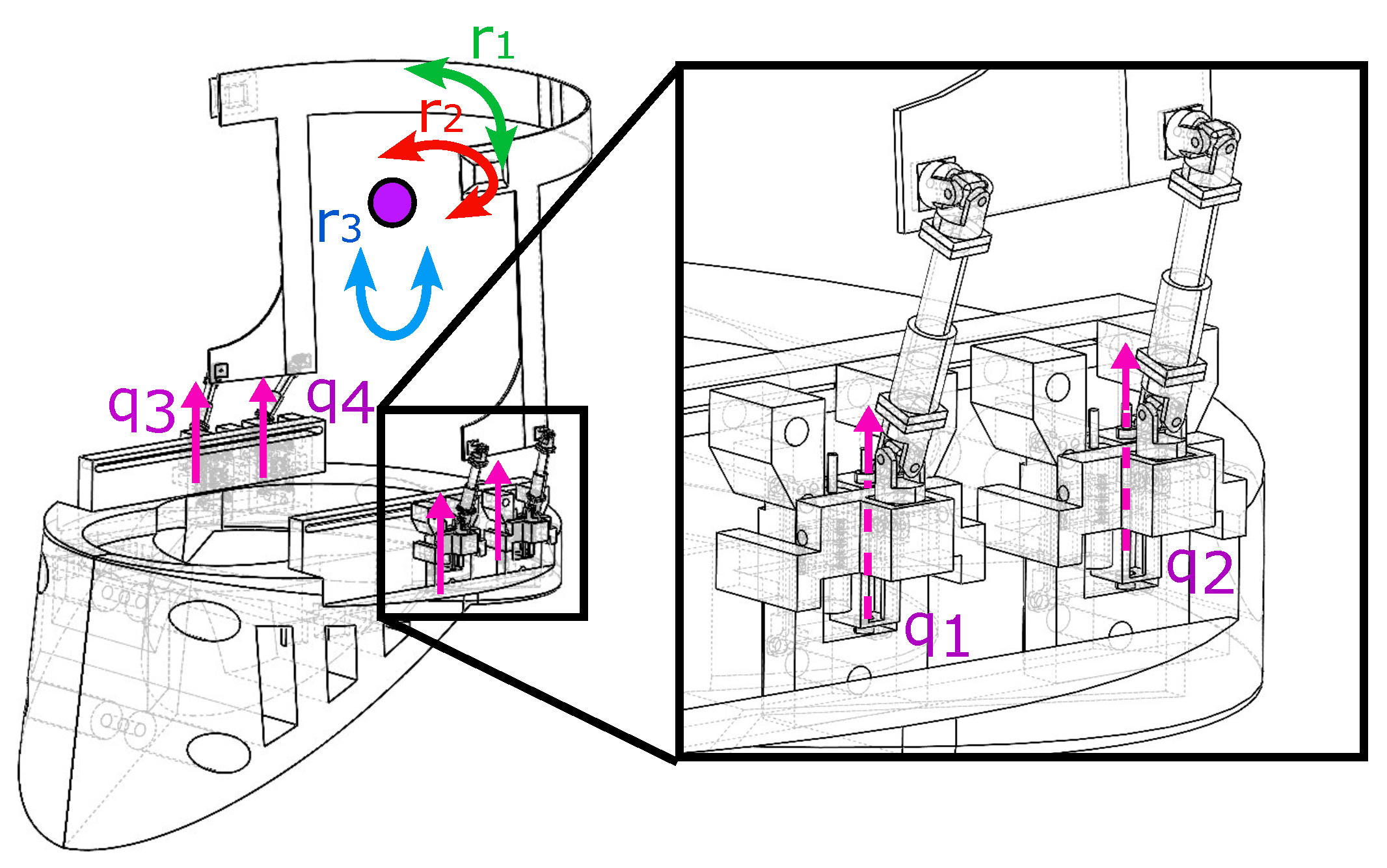
The movement of actuators allows to control the range, and the trajectory of the neck during rehabilitation therapies. The corresponding motion trajectories should be suggested by professional physicians. Figure 2 shows the class of actuators selected for the orthosis. The orthosis employs linear actuators that generates a movement in the x-y direction.
Once the proposal design was approved, the CAD design is exported to Simulink in Matlab to prove the orthosis in a virtual environment. The SimMechanics environment allows to prove virtually the functions of the orthosis. With the measurements of position and velocity obtained from SimMechanics, it is possible to evaluate the control performance for a future implementation. The control must satisfy the neck motion for the rehabilitation according to the trajectories suggested by physicians.
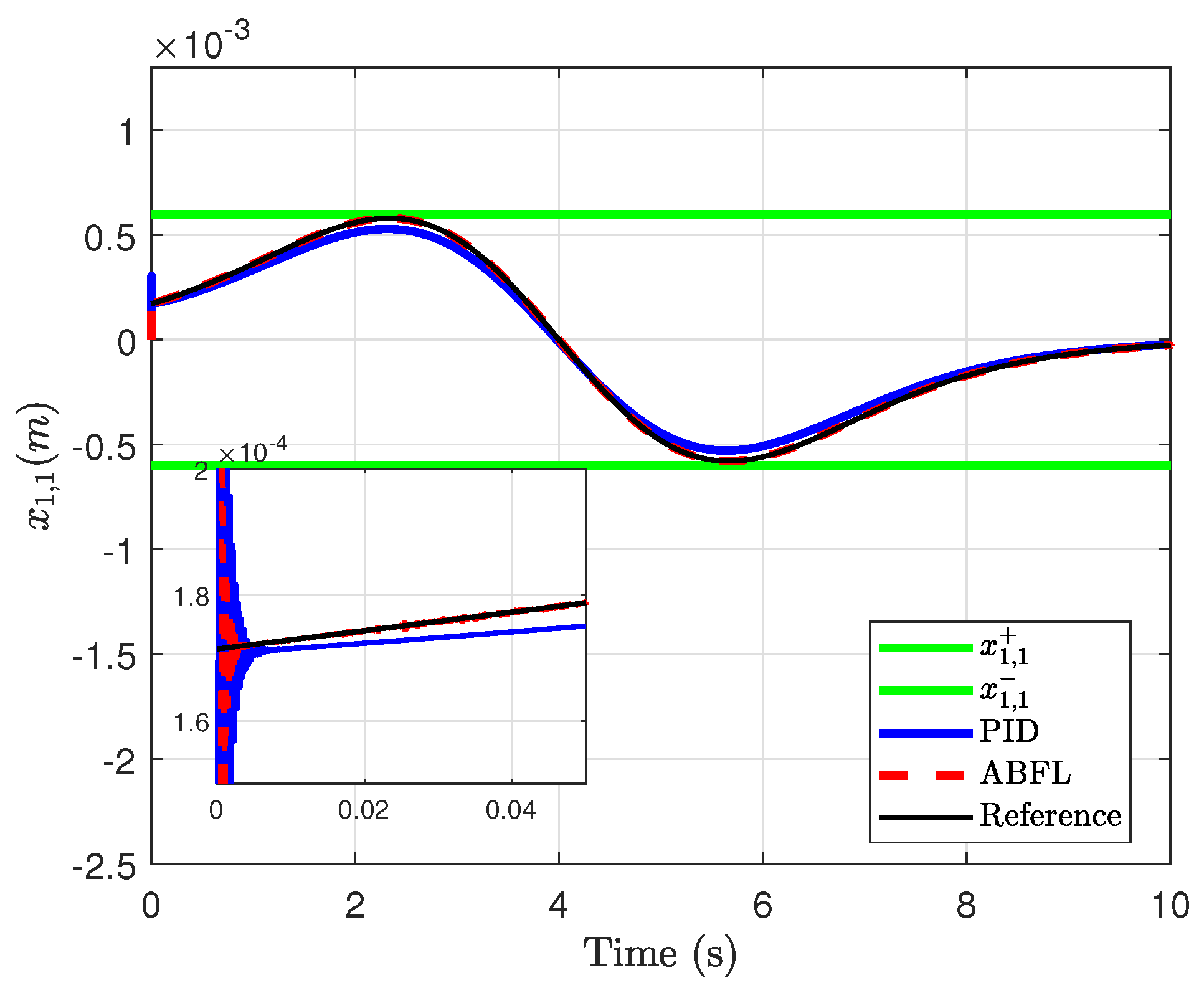
A comparison is done employing a classical PID controller. The control gains employed in this controller are k P = 10 , k D = 2.5 and k I = 0.5 . For the FOSM controller the gains are γ = 0.002 , μ i = 0.1 . The positive restriction in position is 5.795 × 10 4 m, while the negative restrictions is 5.725 × 10 4 m, the restrictions in velocity were 1 cm/s and 1.3 cm/s. Figure 3 shows the results obtained with the proposed asymmetric FOSM controller. Notice that the position of the orthosis follows the desired trajectories without violating the state restrictions. A comparison against a classical proportional–integral–derivative (PID) controller demonstrates the advantages using the analysis based on BLF. Even though, the results obtained with the PID strategy do not violates the asymmetric state restrictions imposed on the orthosis, the trajectories do not reach the desired ones. Figure 4 describes the tracking trajectory task for the velocity. Similar to previous results the trajectories remain inside the constraints. The initial overshoot presented by the PID controller does not fulfill the state restrictions, while the overshoot provided by the asymmetric FOSM that is smaller than the PID remains inside the restrictions. Notice that the convergence is improved applying the controller proposed in this manuscript. Figure 5 describes the control signal obtained with each approach. Finally, Figure 6 shows the comparison of the tracking error obtained with the PID and the AFOSM. The tracking error resulted from applying the PID is bigger than the one obtained with the AFOSM. These numerical simulations corroborate the theoretical results showed in Theorem 1.

7. Conclusions

This manuscript showed the control of an orthotic cervical device assuming asymmetric state restrictions based on FOSM and ABLF. The stability analysis demonstrated the finite-time convergence of the nonlinear system towards the sliding surface and consequently, asymptotic convergence of the tracking error. Numerical results compared the trajectories obtained with classical controllers showing how the trajectories do not fulfil the restrictions when a PID is applied. Further research should be oriented to study time-varying restrictions based on sliding mode approaches and to validate through a clinical study the advantages of using these active devices.

Author Contributions

The work described in this article is the collaborative development of all authors. Methodology and experiments simulation, C.M. and A.L.; writing—original draft preparation and conceptualization, D.C.-O.; Methodology, writing—review and editing, and project administration, M.B. and I.S. All authors have read and agreed to the published version of the manuscript.

Funding

This research was funded by Instituto Politécnico Nacional grant numbers SIP-20221150, SIP-20220916, SIP-20221506, SIP-20226963, SIP-20221746.

Conflicts of Interest

The authors declare no conflict of interest.

Abbreviations

The following abbreviations are used in this manuscript:
BLFBarrier Lyapunov function
ABLFAsymmetric Barrier Lyapunov function
SMSliding modes
FOSMFirst order sliding modes

References

  1. Bonato, P. Advances in Wearable Technology and Applications in Physical Medicine and Rehabilitation. J. Neuroeng. Rehabil. 2005, 2, 1–4. [Google Scholar] [CrossRef] [PubMed] [Green Version]
  2. Onose, G.; Morcov, M.V.; Sporea, C.; Mirea, A.; Ciobanu, V. Augmentation and Rehabilitation with Active Orthotic Devices. In Modern Ap-proaches to Augmentation of Brain Function; Springer: Cham, Switzerland, 2021; pp. 521–548. [Google Scholar] [CrossRef]
  3. Gavin, T.; Carandang, G.; Havey, R.; Flanagan, P.; Ghanayem, A.; Patwardhan, A. Biomechanical analysis of cervical orthoses in flexion and extension: A comparison of cervical collars and cervical thoracic orthoses. J. Rehabil. Res. Dev. 2003, 40, 527–537. [Google Scholar] [CrossRef] [PubMed]
  4. Kalita, B.; Narayan, J.; Dwivedy, S.K. Development of active lower limb robotic-based orthosis and exoskeleton devices: A systematic review. Int. J. Soc. Robot. 2021, 13, 775–793. [Google Scholar] [CrossRef]
  5. Ter Wengel, P.V.; de Witt Hamer, P.C.; Pauptit, J.C.; van der Gaag, N.A.; Oner, F.C.; Vandertop, W.P. Early surgical decompression improves neurological outcome after complete traumatic cervical spinal cord injury: A meta-analysis. J. Neurotrauma 2019, 36, 835–844. [Google Scholar] [CrossRef] [PubMed]
  6. Yozbatiran, N.; Francisco, G.E. Robot-assisted therapy for the upper limb after cervical spinal cord injury. Phys. Med. Rehabil. Clin. 2019, 30, 367–384. [Google Scholar] [CrossRef] [PubMed]
  7. Lendraitienė, E.; Smilgiene, L.; Petruseviciene, D.; Savickas, R. Changes and Associations between Cervical Range of Motion, Pain, Temporomandibular Joint Range of Motion and Quality of Life in Individuals with Migraine Applying Physiotherapy: A Pilot Study. Medicina 2021, 57, 630. [Google Scholar] [CrossRef] [PubMed]
  8. Bell, K.M.; Frazier, E.; Shively, C.; Hartman, R.A.; Ulibarri, J.C.; Lee, J.Y.; Kang, J.D.; Donaldson, W.F. Assessing range of motion to evaluate the adverse effects of ill-fitting cervical orthoses. Spine J. Off. J. N. Am. Spine Soc. 2009, 9 3, 225–231. [Google Scholar] [CrossRef]
  9. Frigo, C.; Pavan, E. Prosthetic and Orthotic Devices. Assist. Technol. Concepts Methodol. Tools Appl. 2013, 549–613. [Google Scholar] [CrossRef]
  10. Karimi, M.T.; Kamali, M.; Fatoye, F. Evaluation of the efficiency of cervical orthoses on cervical fracture: A review of literature. J. Craniovertebral Junction Spine 2016, 7, 13. [Google Scholar] [CrossRef]
  11. Johnson, R.M.; Hart, D.L.; Owen, J.R.; Lerner, E.; Chapin, W.; Zeleznik, R. The yale cervical orthosis: An evaluation of its effectiveness in restricting cervical motion in normal subjects and a comparison with other cervical orthoses. Phys. Ther. 1978, 58, 865–871. [Google Scholar] [CrossRef] [PubMed]
  12. Sarma, J.; Sahai, N.; Bhatia, D. Recent advances on ankle foot orthosis for gait rehabilitation: A review. Int. J. Biomed. Eng. Technol. 2020, 33, 159–173. [Google Scholar] [CrossRef]
  13. Lochner, S.; Huissoon, J.; Bedi, S. Parametric Design of Custom Foot Orthotic Model. Comput.-Aided Des. Appl. 2013, 9, 1–11. [Google Scholar] [CrossRef] [Green Version]
  14. White, A. Some Comments on Cervical Orthoses. In Clinical Prosthetics and Orthotics; 2022; Available online: http://www.oandplibrary.org/cpo/pdf/1983_03_005.pdf (accessed on 26 August 2022).
  15. Kumar, R.; Prakash, A. Efficacy of cervical orthoses in improving neck control of growing children with cerebral palsy: A narrative review. J. Indira Gandhi Inst. Med Sci. 2021, 7, 90. [Google Scholar] [CrossRef]
  16. Ricotta, V.; Campbell, R.; Ingrassia, T.; Nigrelli, V. A new design approach for customised medical devices realized by additive manufacturing. Int. J. Interact. Des. Manuf. (IJIDeM) 2020, 14, 1–8. [Google Scholar] [CrossRef]
  17. Iradi, I.; Zulueta, E.; Teso-Fz-Betoño, D.; Saenz-Aguirre, A.; Fernandez-Gamiz, U. Modeling of Motorized Orthosis Control. Appl. Sci. 2019, 9, 2453. [Google Scholar] [CrossRef] [Green Version]
  18. Zhang, H.; Chang, B.; Andrews, J.; Mitsumoto, H.; Agrawal, S. A robotic neck brace to characterize head-neck motion and muscle electromyography in subjects with amyotrophic lateral sclerosis. Ann. Clin. Transl. Neurol. 2019, 6, 1671–1680. [Google Scholar] [CrossRef] [PubMed] [Green Version]
  19. Font-Llagunes, J.; Pàmies-Vilà, R.; Alonso, J.; Lugrís, U. Simulation and design of an active orthosis for an incomplete spinal cord injured subject. Procedia IUTAM 2011, 2, 68–81. [Google Scholar] [CrossRef]
  20. Chang, B.C.; Zhang, H.; Trigili, E.; Agrawal, S.K. Bio-Inspired Gaze-Driven Robotic Neck Brace. In Proceedings of the 2020 8th IEEE RAS/EMBS International Conference for Biomedical Robotics and Biomechatronics (BioRob), New York, NY, USA, 29 November–1 December 2020; pp. 545–550. [Google Scholar] [CrossRef]
  21. Guzman-Victoria, I.; Salgado, I.; Mera, M.; Chairez, I.; Ahmed, H. Impedance Adaptive Controller for a Prototype of a Whiplash Syndrome Rehabilitation Device. Math. Probl. Eng. 2019, 2019, 1–21. [Google Scholar] [CrossRef]
  22. Zhang, H.; Santamaria, V.; Agrawal, S. Applying Force Perturbations Using a Wearable Robotic Neck Brace. In Proceedings of the 2020 IEEE/RSJ International Conference on Intelligent Robots and Systems (IROS), Las Vegas, NV, USA, 25–29 October 2020; pp. 4197–4202. [Google Scholar] [CrossRef]
  23. Cruz-Ortiz, D.; Chairez, I.; Poznyak, A. Sliding-Mode Control of Full-State Constraint Nonlinear Systems: A Barrier Lyapunov Function Approach. IEEE Trans. Syst. Man Cybern. Syst. 2022, 52, 6593–6606. [Google Scholar] [CrossRef]
  24. Tee, K.P.; Ge, S.S.; Tay, E.H. Barrier Lyapunov functions for the control of output-constrained nonlinear systems. Automatica 2009, 45, 918–927. [Google Scholar] [CrossRef]
  25. Mera, M.; Salgado, I.; Chairez, I. Robust observer-based controller design for state constrained uncertain systems: Attractive ellipsoid method. Int. J. Control 2020, 93, 1397–1407. [Google Scholar] [CrossRef]
  26. Li, Y.X. Barrier Lyapunov function-based adaptive asymptotic tracking of nonlinear systems with unknown virtual control coefficients. Automatica 2020, 121, 109181. [Google Scholar] [CrossRef]
  27. Salgado, I.; Mera, M.; Chairez, I. Suboptimal adaptive control of dynamic systems with state constraints based on barrier lyapunov functions. IET Control Theory Appl. 2018, 12, 1116–1124. [Google Scholar] [CrossRef]
  28. Yang, G.; Yao, J.; Dong, Z. Neuroadaptive learning algorithm for constrained nonlinear systems with disturbance rejection. Int. J. Robust Nonlinear Control 2022, 32, 6127–6147. [Google Scholar] [CrossRef]
  29. Cruz-Ortiz, D.; Chairez, I.; Poznyak, A. Non-singular terminal sliding-mode control for a manipulator robot using a barrier Lyapunov function. ISA Trans. 2022, 121, 268–283. [Google Scholar] [CrossRef]
  30. Zhang, H.; Chang, B.C.; Agrawal, S.K. Using a robotic neck brace for movement training of the head–neck. IEEE Robot. Autom. Lett. 2019, 4, 846–853. [Google Scholar] [CrossRef]
  31. Lozano, A.; Ballesteros, M.; Cruz-Ortiz, D.; Chairez, I. Active neck orthosis for musculoskeletal cervical disorders rehabilitation using a parallel mini-robotic device. Control Eng. Pract. 2022, 128, 105312. [Google Scholar] [CrossRef]
  32. Nocedal, J.; Wright, S.J. Numerical Optimization; Springer Series in Operations Research and Financial Engineering; Springer: New York, NY, USA, 2006; pp. 1–663. Available online: https://link.springer.com/book/10.1007/978-0-387-40065-5 (accessed on 26 August 2022).
  33. Polyakov, A.; Fridman, L. Stability notions and Lyapunov functions for sliding mode control systems. J. Frankl. Inst. 2014, 351, 1831–1865. [Google Scholar] [CrossRef]
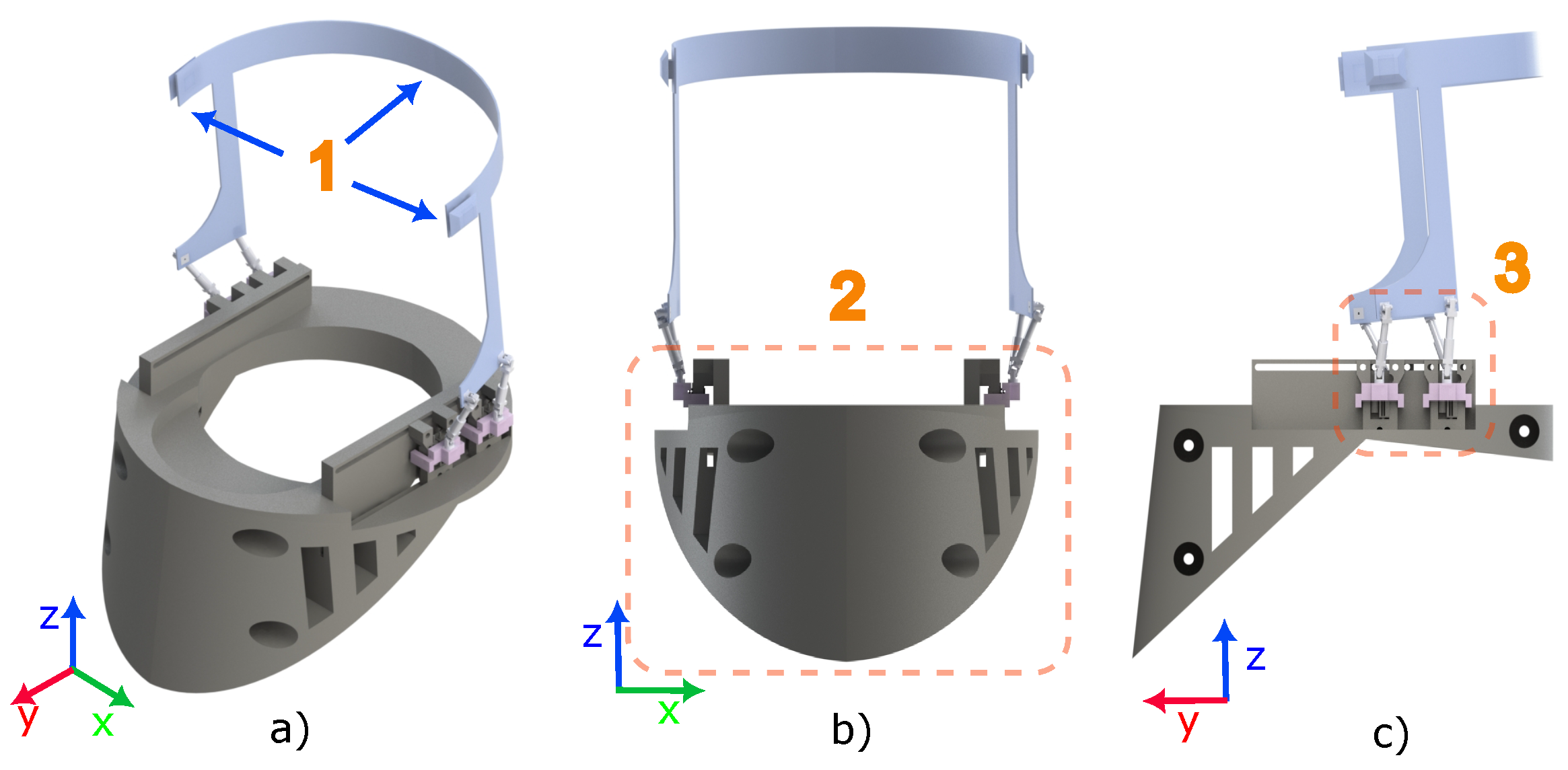
Figure 1. Orthosis design in a CAD software. (a) Isometric view; (b) frontal view; and (c) lateral view.
Applsci 12 10286 g001
Figure 2. The mechanism of movement generated by a set of linear actuators. The closer view describes the position and orientation of the actuators.
Applsci 12 10286 g002
Figure 3. Tracking trajectory of position.
Applsci 12 10286 g003
Figure 4. Tracking trajectory of velocity.
Applsci 12 10286 g004
Figure 5. Control signal.
Applsci 12 10286 g005
Figure 6. Tracking error for the position.
Applsci 12 10286 g006
Publisher’s Note: MDPI stays neutral with regard to jurisdictional claims in published maps and institutional affiliations.