Abstract
One of the directions for expanding the functional properties of modular draft devices (MDD) is their use with semitrailers (using a fifth-wheel coupling, installed on the technological module). The issue with this is due to their ability to create such a redistribution of the MDD operational mass along the semitrailer’s axles whereby the loss of control of the entire transport aggregate is possible. To solve this problem, regularities have been established to consider in choosing the design parameters of the MDD. It has been established by theoretical calculations that an increase in the angle of inclination of the central α, with negative values of the angle of inclination of the lower β links of the rear-mounted mechanism of the MDD’s power module (PM), leads to an increase in the vertical load of the wheels of its technological module. The transition of the longitudinal coordinate point of the semitrailer’s tractive resistance application from −0.30 m to +0.30 m, provided α > β, leads to an increase in the vertical load on the wheels of its technological module. Increasing the angles of inclination of the central and lower links of the rear linkage of the PM leads to an increase in the vertical load on the wheels of its front axle. An exception is the option in which the lower links of the specified linkage mechanism are set at a negative angle at the level of −10°. An increase in the value of the angle of inclination of the central value, with positive values of the angle of inclination of the lower links of the rear-mounted mechanism of the PM, and compliance with the condition α < β, leads to a decrease in the vertical load of the wheels of the technological module.
1. Introduction
One of the modern directions in building new tractors is their design in the form of modular draft devices (MDD). The theoretical foundations for the creation of the MDD are described in sufficient detail in [1].
Structurally, an MDD consists of a power module (PM) and a technological module (TM) (Figure 1). The power module is a tractor that is equipped with a ground-speed power take-off (GSPTO). The technology module is an additional axle (rear-drive axle), attached to the rear three-point linkage of the power module (tractor). During its operation, the central and lower links of this mechanism are in a “floating” position. The TM wheels are driven by the GSPTO. In order to connect various agricultural machines, the technological module has its own mounted mechanism, as well as a fifth-wheel coupling for aggregating semitrailers (pos. 2, Figure 1).
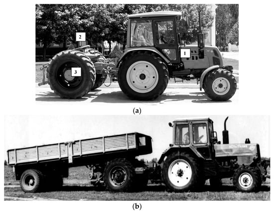
Figure 1.
Modular draft device: (a) general view of MDD with fifth-wheel coupling, (b) unit in operation: (1) power module (PM); (2) saddle semitrailer device; (3) technological module (TM).
The use of an MDD as part of the tractive aggregates in ploughing shows that the presence of a three-point linkage between the modules of the tractive means can significantly increase the stability of the plough movement in a longitudinal-vertical plane [2]. In addition, studies of the dynamics of the movement of the aggregate, based on the MDD, were carried out when it was moving with the machine in a transport position [1].
It should be remarked that such a result is quite logical, because the vertical load, acting upon the technological module MDD, is relatively small, and it is not capable of causing significant unloading of its front-driven wheels.
Thus, the improvements we propose relate to a significant expansion of the functionality of this transport and power aggregate. Namely, the power module (the wheeled tractor) (position 1 in Figure 1a) can be used for its intended purpose of performing various agricultural operations (the aggregation of ploughs, seeders, cultivators and other mounted and trailed agricultural implements, as well as for light trailers). The use of a wheeled tractor as an independent power tool is limited by its capabilities, namely, the tractive effort that it can deliver.
In this version, to improve the tractive properties of a wheeled tractor, a technological module (position 3 in Figure 1a) (GSPTO) is used, which significantly increases the tractive properties of the tractor. This allows the aggregate proposed by us (wheeled tractor + GSPTO) to aggregate a larger number of agricultural machines; additionally, this makes it possible to successfully transport heavy semitrailers. The new constructive solution we propose also makes it possible to turn the combination of a power vehicle (a wheeled tractor) and a technological module (GSPTO) into a truck tractor. The design of the technological module (position 3 in Figure 1a) includes a coupling device (position 2 in Figure 1a) located in its upper part. The operation of a truck tractor, based on a powerful car, in agricultural production (when driving both in the field and on the roads) is often inefficient or even impossible. A general view of this transport aggregate is shown in Figure 1b.
A different result may be obtained when driving an MDD with a loaded semitrailer. In this case, a significant (at the level of 30 kN) vertical load could cause trouble on the TM. In combination with the horizontal component of the tractive resistance of the semitrailer, these forces can cause a significant redistribution of the vertical loads on the MDD axles. In real conditions, this can lead to: (i) an unloading of the driven wheels of the PM; (ii) an overload of the TM wheels; (iii) a joint manifestation of both of these options.
It is quite evident that this situation can be regulated by the correct choice of the installation angles in the longitudinal-vertical plane of the central α and lower β links of the rear-mounted mechanism PM. In this case, obviously, a significant role will be played by the longitudinal coordinate of the installation of the saddle semitrailer coupling on the TM frame.
In the transport of automobiles, semitrailers are used with truck tractors. The latter have a different wheel formula. First of all, these are six-wheeled tractors, where the front axle has two wheels and the rear axle has four wheels. Semitrailers, coupled with truck tractors, have one [3], two [4,5] or three axles [6,7].
There have been developed mathematical models of the movement of aggregates as part of an eight-wheeled truck tractor with an active drive of four axles and a semitrailer with three axles [8]. In addition, the wheels of each axle of the semitrailer have an active drive.
However, the tractors with three axles are not structurally similar to the MDDs. First of all, this is because their third axle in the longitudinal-vertical plane is effectively also fixed on the tractor frame, as are the front and middle ones. This means that, between the second and the third axles of the tractor, there is no such flexible kinematic connection as exists between the rear axle of the power module and the axle of the MDD technological module.
Based on this, in the known types of tractors, the necessary distribution of the vertical loads over their axles can only be achieved by changing the longitudinal coordinate of the point of attachment to the semitrailer. When using an MDD, there is a compromise to solve such a problem. It consists of setting the desired values of the above-mentioned inclination angles of the central and lower links of the rear linkage of the MDD power module.
One of peculiarities of the use of truck tractors with semitrailers is the potential ability to unload the front-driven wheels of the tractor. To evaluate this result, there is a special indicator. According to this, the controllability of a tractive vehicle is considered satisfactory if at least 20% of the operating weight falls on its front axle [9].
In the work [10], a new indicator is proposed that takes into account: (i) the angle of inclination of the surface along which the machine-tractor (including the transport one) aggregate moves; (ii) the turning angle of the driven wheels of the tractor; (iii) the slip angle of the front wheels of the tractor; and (iv) the ballasting level on the front wheels of the tractor. The application of this indicator makes it possible to obtain more adequate results for the assessment of the controllability of the tractor. When working with a semitrailer, this is of particular relevance.
An acceptable assessment of the controllability of any machine-tractor aggregate is possible if information is available on the dynamics of the distribution of the vertical loads along the tractor axles. For its biaxial design, the solution of such a problem does not present any difficulty. The work of many researchers is devoted to the study of the stability of the movement of tractor semitrailers [11,12]. Moreover, when using a tractor with both conventional two-axle trailers [13] and trailers with active wheel drive [14], it is suggested to use the utilization factor of its own operating weight [15].
For three-axle tractors with semitrailers, the task of studying the dynamics of changes in the vertical loads on the axles is rather problematic, mainly because, in the longitudinal-vertical projection plane, such a transport aggregate is a statically indeterminate system. Based on this, the currently developed analytical and experimental approaches to studying the nature of the distribution of the vertical loads over the axles of a three-axle tractor, when it is operating with a semitrailer [16], are practically not suitable for solving a similar problem with respect to a transport aggregate.
The purpose of this work is to develop theoretical foundations for the choice of the design parameters of a modular draft device with a semitrailer that ensures satisfactory controllability of the movement of the transport aggregate.
2. Theoretical Premises
In order to draw up a design scheme, we will consider an option where the following external forces and movements act upon the modular draft device in the process of its movement with a semitrailer (Figure 2): , , (kN); , , (kN); , and (kN∙m) are the tractive forces, as well as the forces and movements of the rolling resistance of the front, rear and technological axles of the MDD, respectively; is the front axle ballast weight force MDD, kN; , and are the surface reaction forces, kN; and are the forces of the weight of the power and technological modules of the MDD, respectively, kN; and are the reactions at the point , kN; and are the horizontal and vertical components of the tractive resistance of the semi-mounted trailer, kN.

Figure 2.
Scheme of forces acting upon the transport.
Three of these movements and forces are unknown: , and . For their definition, it is necessary, as it is known, to have three independent MDD equilibrium equations in the longitudinal-vertical plane. In reality, we have only two such equations, namely: (i) the sum of the forces on the axis; and (ii) the sum of the movements relating to some point. Since there are three unknown forces, and two independent equations of equilibrium, we obtain a statically indeterminate system. To solve this, it is proposed to consider the balance of the power and technological modules of the MDD separately.
At first, we will do this with the technology module. We will replace the influence of the PM on the TM in the longitudinal-vertical plane with reactions and , concentrated in point (Figure 2). This is formed as a result of the intersection of the directions of the central and the lower links of the rear-mounted EM mechanism, and it represents the instantaneous center of rotation of this mechanism in the longitudinal-vertical plane. As a result of this approach, we obtain a state of the TM in which three unknown forces act upon it: , and . However, now, three well-known equilibrium equations of the system under consideration are sufficient to determine them.
The impact of the TM upon the PM is expressed by the same modulus, yet opposite in direction and the already known reactions and applied at the same point and indicated in Figure 2 with a dotted line. In this case, only two unknown forces act upon the PM: and . To determine these, two equilibrium equations of the given system are sufficient. Namely: (i) the sum of the forces on the axis; and (ii) the sum of the movements in relation to (Figure 2).
As a result, the equilibrium of the entire MDD in the longitudinal-vertical plane is described by the following system of five equations:
In the system of Equation (1), the following designations are accepted: —adhesion coefficient the tire to the soil; —coefficient of rolling resistance; , , —rolling radii of the front and rear wheels of the power module, as well as the wheels of the technological module (m); , , , , , (m)—design parameters (see Figure 2).
The parameters and depend on the installation angles of the central and lower links of the rear-mounted mechanism of the MDD power module (Figure 3). In further investigations, we will discuss three options for setting this mechanism (Table 1). In addition, we will agree to consider the angle to be positive if it is located in the first quadrant of the coordinates, and negative if it is located in the fourth quadrant. With this in mind, angle , displayed in Figure 3, is positive, and angle is negative.
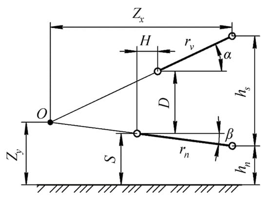
Figure 3.
Kinematic diagram of the rear attachment mechanism of the tractor.

Table 1.
Formulas for determining the parameters of the rear attachment of the tractor (Figure 3).
The negative values of angle are not considered since, with such an installation of the central link, the rear-mounted mechanism PM becomes inoperative.
From the analysis of the expressions in Table 1, it follows that, in addition to the angles and , parameters and depend on the height of the connection of the lower links of the power module to the frame of the TM and , and the height of the connecting mechanism of this module, . Their values can be determined from the following expressions (see Figure 3):
where is the length of the lower links of the power module hitch, m.
It should also be recalled that, in Equation (3), the term is equal to , where is the length of the central link of the power module hitch, m.
To assess the level of the vertical load of the front wheels of the tractor, the controllability index was used in the following form [10]:
where g = 9.81 m∙s−2; is the angle of inclination of the MDD’s moving surface with a semitrailer (grad.); , is the angle of turning and the slip angle of the front-driven wheels of the tractor, respectively; is the coefficient of the friction of rubber (the tire) along the soil; and is the speed of the MDD with a semitrailer (m∙s−1).
3. Materials and Methods
The tractor KIY-14800 (Kyiv, Ukraine) was chosen as the MDD power module. Its front-driven wheels are equipped with 11.2R20 tires and its body with 16.9R30 tires (Figure 1). The tires of the wheels of the technological module have the same dimensions, i.e., 16.9R30.
In the process of the theoretical calculations, the following values of the parameters included in Equations (1)–(4) were used:
γ = 5°; φ = 10°; δ = 1°; ft = 0.4; φt = 0.7; f = 0.08; V = 6.0 m s−1;
H = 0.4 m; S = 0.4 m; D = 0.44 m; h = 1.52 m.
Of the indicated parameters, the values of , , and f are taken from reference books [17]; the values of , and V are calculated and given by the authors of the article. The rest of the design parameters are obtained by direct measurement on a sample MDD with a loaded semi-trailer (Figure 1b).
Coordinate of point D, in which the vertical and horizontal components of the tractive resistance of the semitrailer are concentrated, was changed from −0.30 to +0.30 m. In Figure 2, in particular, the positive direction of this parameter is noted.
As was already mentioned above, in the calculations only the positive values of the angle of inclination of the central link of the rear attachment of the MDD power module were taken into account. The range of the parameter variations was 5–35°.
The values of the angle of inclination of the lower links of the attached PM were changed from −10 to +10°. Calculations were carried out according to an algorithm, the scheme of which is shown in Figure 4.

Figure 4.
Block diagram of the calculation algorithm.
The vertical load of the MDD wheels was evaluated by taking into account the maximum load capacity of the tires on the wheels. The regulatory value of this indicator is determined by the interstate standard, GOST 7463-2005, “Pneumatic tires for tractors and agricultural machines”. In this case, the main attention was paid to the dynamics of the changes in the forces and . The probability of overloading the tires of the rear wheels of the MDD power module (force ) is extremely small.
4. Results and Discussion
In accordance with the first option for setting the rear attachment device of the MDD power module (Table 1), we consider the dependence of the forces and on the change in angle at a zero angle value (i.e., = 0°). An analysis of the calculated data shows the following. At positive values of the parameter (Figure 2), an increase in angle from 5 to 35° leads to an increase in the forces and (Figure 5).
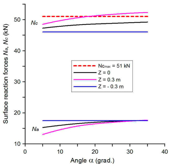
Figure 5.
Dependence of forces and on the angle of installation of the central link of the rear attached mechanism of the tractor with the installed lower = 0°.
However, the regularities of this process for the indicated forces are different. First, at value = 0, the vertical load of the wheels on the front axle of the PM is greater than at = 0.30 m. With the wheels of the MDD technology module, everything is vice versa. Their additional loading is greater, the greater the value of . Such a result is natural, since, with an increase in this parameter, the leverage of the vertical component of the tractive resistance of the semitrailer increases. This force on the arm tends to rotate the TM clockwise and thus loads its wheels.
Second, the smaller the value of angle , the greater the difference in the values of the force for different (but positive!) values of the parameter . For force , this regularity is valid for greater values of angle . Besides, when = 0.30 m, and the value is more than 18°, the vertical load on the TM wheels exceeds their maximum load capacity .
As the positive values of the parameter decrease, the intensity of the change in the forces and decreases. At = −0.30 m and = 0, the dynamics of the changes in these forces is practically independent of the installation angle of the central link of the rear-attached mechanism of the MDD power module.
If, at a positive value of angle , we set the lower links of the attached mechanism of the PM at a negative angle at the level of −10°, then we obtain the following. Only one quantitative change will appear in the dynamics of force . Namely, the excess of the maximum load capacity of the TM tires will occur, not at = 18°, as in the previous case, but at a value of this angle equal approximately to 14° (Figure 6).
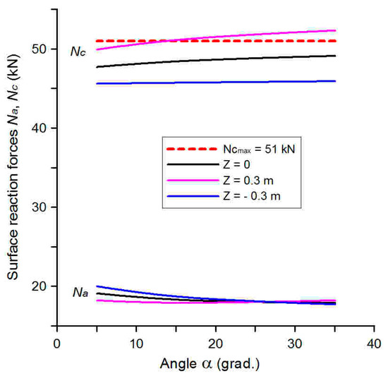
Figure 6.
Dependence of forces and on the angle of installation of the central link of the rear-attachment mechanism of the tractor when installing lower −10°.
As for the dynamics of the change of force , then, unlike in the previous case (Figure 5), as the value of angle increases, the value of the vertical load on the front wheels of the PM, albeit slightly, still decreases. Another thing is that this decrease does not lead to the loss of controllability of the MDD, since the minimum allowed value of force is at the level of 6 kN, which is about 2.5 times less than its real level.
In the second setting variant of the rear attachment of the MDD power module (Table 1), the dynamics of the changes of force (Figure 7) with the increase in angle remains similar to that shown in Figure 5.

Figure 7.
Dependence of forces and on the angle of installation of the central link of the rear-mounted mechanism of the tractor when installing lower 3° ().
Besides, there are significant differences in the force changes. With an increase in angle from 5 to about 15°, there is a relatively intense increase in the vertical load on the wheels of the front axle of the MDD power module, as well as for all the values of the parameter . In addition, at = 5° and = 0.3 m, the value of the force = 4.6 kN becomes less than the minimum allowed, = 6.2 kN. In this case, in order to maintain the controllability of the transport aggregate, the MDD front axle must be equipped with a 165 kg ballast.
A similar situation is obtained with an increase in the installation angle of the lower links of the attached mechanism of the MDD power module up to 10° (Figure 8).

Figure 8.
Dependence of forces and on the installation angle of the central link of the rear-mounted mechanism of the tractor when installing lower 10° ().
In this case, as the calculations show, at angles = 15° and = 10°, the controllability of the transport aggregate will be ensured when the front wheels of the PM are ballasted with a ballast weight of 50 kg.
It turned out that the third variant of setting the rear hinged mechanism of the MDD power module was rather specific. If, in the previous cases, an increase in the value of angle at ≥ 0 determined a certain increase in force (Figure 5, Figure 6, Figure 7 and Figure 8), then, in this variant, there is a decrease (Figure 9). In addition, the value does not exceed the maximum load capacity of the tires of the technological module wheels, even at values of angle close to zero.
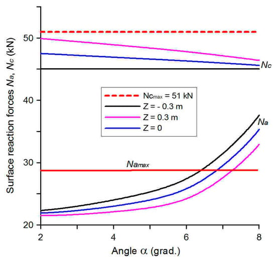
Figure 9.
Dependence of forces and on the installation angle of the central link of the rear-mounted mechanism of the tractor when installing lower 10° ().
The value of the vertical load on the front wheels of the MDD power module increases with a corresponding increase in the value of the angle of installation of the central link of the rear linkage of the PM. At certain values of the parameters and , this increase also reaches such values that exceed the level of the maximum load capacity of the tires of the front axle of the MDD. In particular, at = −0.30 m, this occurs when the angle is approximately 6.5°. At = 0, this is observed when is equal to 7°. In the case of a positive value of the parameter at the level of 0.30 m, this takes place at at approximately 7.5°.
It should be noted that, for all the variants of setting the rear-attached mechanism of the PM, the change in the vertical load on the wheels of the axle of the TM at the value of the parameter = −0.30 m is so small that it practically does not depend on the change in the value of angle .
5. Conclusions
When choosing the design parameters of a modular draft device (MDD) for its work with a semitrailer, the following regularities should be taken into account:
- -
- An increase in the value of the angle of inclination of the central link with the negative values of the angle of inclination of the lower links of the rear-mounted mechanism of the MDD’s power module leads to an increase in the vertical load on the wheels of its technological module. The same result also takes place for the positive values of angle provided that they, by absolute value, do not exceed the value of angle .
- -
- The transition of the longitudinal coordinate of the point of application of the vertical and the horizontal components of the tractive resistance of the semitrailer , from negative values (from −0.30 m) to positive (up to +0.30 m), for all the values of the angles of inclination of the central and lower links of the rear-mounted mechanism of the MDD’s power module, under the condition > , leads to an increase in the vertical load on the wheels of its technological module. In addition, at = +0.30 m and certain values of angles , it is possible to exceed the maximum load capacity of the tires of the wheels of the MDD’s technological module.
- -
- An increase in the value of the angle of inclination of the central link, with the positive values of the angle of inclination of the lower links of the rear-mounted mechanism of the MDD power module and compliance with the condition < , leads to a decrease in the vertical load of the wheels of its technological module.
- -
- Increasing the angles of inclination of the central and the lower links of the rear linkage of the MDD’s power module leads to an increase in the vertical load on the wheels of its front axle. An exception is the variant in which the lower links of the specified linkage mechanism are set at a negative angle at the level of −10°.
- -
- For all the variants of setting the rear-mounted mechanism of the MDD’s power module, the change in the vertical load on the wheels of the axle of the technological module at the value of the parameter = −0.30 m is so small that it practically does not depend on the change in the value of angle .
Author Contributions
Conceptualization, V.B.; methodology, S.I. and V.N.; software, M.R.; validation, A.A. and V.B.; formal analysis, V.B. and S.P.; investigation, V.B., M.R., V.N. and S.P.; data curation, A.A., V.B. and M.R.; writing—original draft preparation, V.B., A.A. and S.I.; writing—review and editing, A.A. and V.B.; visualization, M.R. and V.N.; project administration, V.B.; funding acquisition, H.B. and S.I. All authors have read and agreed to the published version of the manuscript.
Funding
This research received no external funding.
Institutional Review Board Statement
Not applicable.
Informed Consent Statement
Not applicable.
Conflicts of Interest
The authors declare no conflict of interest.
References
- Ivanovs, S.; Bulgakov, V.; Nadykto, V.; Ihnatiev, Y.; Smolinskyi, S.; Kiernicki, Z. Experimental study of the movement controllability of a machine-and-tractor aggregate of the modular type. Inmateh–Agric. Eng. 2020, 61, 9–16. [Google Scholar] [CrossRef]
- Bulgakov, V.; Nadykto, V.; Ivanovs, S.; Dukulis, I. Improving the performance of a ploughing tractor by means of an auxilary carriage with motorized axle. J. Agric. Eng. 2021, 52, 8. [Google Scholar] [CrossRef]
- Wang, X.; Liang, Y.; Shi, G.; Huang, C.; Ying, G. A study on the asynchronous brake lock-up of a statically indeterminate tractor with an air suspension. Proc. Inst. Mech. Eng. Part D J. Automob. Eng. 2012, 226, 507–516. [Google Scholar] [CrossRef]
- Hussain, K.; Stein, W.; Day, A.J. Modelling commercial vehicle handling and rolling stability. Proc. Inst. Mech. Eng. Part K J. Multi-Body Dyn. 2005, 219, 357–369. [Google Scholar] [CrossRef]
- Sakhno, V.; Poliakov, V.; Timkov, O.; Kravchenko, O. Lorry convoy stability taking into account the skew of semitrailer axes. Transp. Probl. 2016, 11, 69–76. [Google Scholar] [CrossRef]
- Diachuk, M.; Lykhodii, O.; Leontiev, D.; Ryzhykh, L.; Aleksandrov, Y. Dynamic modeling of semitrailer trucks equipped by steered wheels. J. Mech. Eng. Sci. 2022, 16, 8691–8705. [Google Scholar] [CrossRef]
- Elhemly, M.A.E.; Fayed, M.A.E.; Elmaihy, A.A.E. Tractor-semitrailer jackknifing elimination using semitrailer differential braking technique. Int. J. Heavy Veh. Syst. 2013, 20, 19–34. [Google Scholar] [CrossRef]
- Chudakov, O.; Gorelov, V.; Padalkin, B. Mathematical Modeling of a Linear Motion on a Deformable Bearing Surface of a Saddle-Type Road Train with Active Semitrailer Element. IOP Conf. Ser. Mater. Sci. Eng. 2020, 820, 012009. [Google Scholar] [CrossRef]
- Janulevičius, A.; Giedra, K. Tractor ballasting in field work. Mechanika 2008, 73, 27–34. [Google Scholar]
- Bulgakov, V.; Adamchuk, V.; Nadykto, V.; Kyurchev, V.; Nozdrovicky, L. Theoretical consideration of the controllability indicator of machine-tractor unit movement. Acta Technol. Agric. 2017, 20, 11–18. [Google Scholar] [CrossRef]
- Xu, X. Lateral Stability Control of a Tractor-Semitrailer at High Speed. Machines 2022, 10, 716. [Google Scholar] [CrossRef]
- Gagnon, L.; Richard, M.J.; Doré, G. A multibody dynamics model to assess the impact of road unevenness on the efficiency of a semitrailer truck. Int. J. Veh. Syst. Model. Test. 2015, 10, 1–28. [Google Scholar] [CrossRef]
- Janulevičius, A.; Giedra, K. The slippage of the driving wheels of a tractor in a cultivated soil and stubble. Transport 2009, 24, 14–20. [Google Scholar] [CrossRef]
- Janulevičius, A.; Pupinis, G. Power circulation in driveline system when the wheels of tractor and trailer are driven. Transport 2013, 28, 313–321. [Google Scholar] [CrossRef]
- Janulevičius, A.; Giedra, K. Tractor ballasting in field transport work. Transport 2005, 20, 146–153. [Google Scholar] [CrossRef]
- Barickman, F.; Elsasser, D.; Albrecht, H.; Church, J.; Xu, G. Tractor Semitrailer Stability Objective Performance Test Research–Roll Stability; Final Report, DOT HS 811 467; National Highway Traffic Safety Administration’s (NHTSA’s): Washington, DC, USA, 2011; 205p. [Google Scholar]
- Guskov, V.V.; Velev, N.N.; Atamasov, Y.E.; Bocharov, N.F.; Ksenevich, I.P.; Solonskyi, A.S. Tractors: Theory; Mashinostroenie: Moscow, Russia, 1988; 376p. (In Russian) [Google Scholar]
Publisher’s Note: MDPI stays neutral with regard to jurisdictional claims in published maps and institutional affiliations. |
© 2022 by the authors. Licensee MDPI, Basel, Switzerland. This article is an open access article distributed under the terms and conditions of the Creative Commons Attribution (CC BY) license (https://creativecommons.org/licenses/by/4.0/).