Article

Terahertz Resonators Based on YBa2Cu3O7 High-Tc Superconductor

by
Salvatore Macis
1,2,*,†,
Maria Chiara Paolozzi
3,†,
Annalisa D’Arco
1,2,
Luca Tomarchio
1,4,
Alessandra Di Gaspare
5 and
Stefano Lupi
1,4
1
Department of Physics, Sapienza University, Piazzale Aldo Moro 5, 00185 Rome, Italy
2
INFN Laboratori Nazionali di Frascati, Via Enrico Fermi 54, 00044 Frascati, Italy
3
Department of Science, Roma Tre University, Viale Guglielmo Marconi, 446, 00146 Rome, Italy
4
INFN Section of Rome, P.Le Aldo Moro, 2, 00185 Rome, Italy
5
NEST, CNR Istituto Nanoscienze, Piazza San Silvestro 12 56127 Pisa, Italy
*
Author to whom correspondence should be addressed.
These authors contributed equally to this work.
Appl. Sci. 2022, 12(20), 10242; https://doi.org/10.3390/app122010242
Submission received: 5 July 2022 / Revised: 20 September 2022 / Accepted: 8 October 2022 / Published: 12 October 2022

Abstract

:
Superconducting split-ring resonator arrays allow to overcome two main limitations affecting metallic metamaterial resonating in the terahertz (THz) range: ohmic losses and tunability of their optical response. In this work, we design and experimentally realize direct and complementary square arrays of superconducting YBa2Cu3O7 (YBCO) split-ring resonators working in the THz spectral range. The main purpose of this paper is to show how the metamaterial resonances can be tuned by temperature (T) when crossing the superconducting transition temperature Tc of YBCO. The tuning property can be quantified by describing the THz transmittance of the patterned YBCO films vs. T through a model of coupled resonators. This model allows us to estimate the THz resonances of split-ring arrays and their interaction, showing how the kinetic inductance Lk in the superconducting state is the main parameter affecting the metamaterial properties.

1. Introduction

Metamaterials (MMs) are artificial engineered systems exhibiting a geometrically scalable electric and/or magnetic resonant response in a broad spectral range from microwaves to visible [1,2,3,4,5,6,7,8,9]. Indeed, thanks to specific patterning, the optical response of these systems can be engineered with respect to the original material, paving the way to innovative opto-electronic applications.
The most widely spread MMs are constituted of periodically patterned thin metallic films deposited on a dielectric substrate, enabling to trigger unusual electromagnetic properties, ranging from superlenses [10] to sensors [11,12], light induced transparency [13], chiral devices [14], filters [15], and modulators [16]. However, two main issues limit the practical applications of metallic metamaterial devices: ohmic losses and tunability. For operational frequencies increasing toward the terahertz (THz), infrared, and visible range, ohmic losses are strongly enhanced, reducing the quality factor of resonances and therefore their tunability. To overcome these drawbacks, the use of superconducting materials has been proposed and innovative metamaterial structures have been realized [17,18,19,20,21,22,23,24]. Several works showed the low-loss properties of superconductors at finite frequency and their sensitivity to external stimuli, such as temperature, magnetic field, and light-pulses, which can be exploited to provide a robust tunability of the device response [19,20,21,22,23,24]. These stimuli affect the superconducting state in a different way [25]. While temperature and magnetic field normally change the thermodynamic equilibrium of a superconductor, an optical pulse with a frequency over the superconducting gap instantaneously creates a metastable state with an excess of unpaired electrons. This also provides an effective way for modulating the superconducting state and finally the resonance frequency of a metamaterial [26]. More specifically, high-temperature superconductor cuprates (HTSCs) are the suitable candidate for facing this challenge since they provide a much broader frequency range of tunability compared to conventional Bardeen–Cooper–Schrieffer (BCS) superconductors, extending beyond 10 THz [27,28]. Furthermore THz radiation is a highly interesting spectral range for multidisciplinary research in physics, chemistry, biology, materials science, and biomedicine [29]. New R&D projects are needed for the realization of high-power compact THz sources, more sensitive detectors, and new metamaterial-based THz optical components [29]. In this framework, superconductors can be used for developing tunable devices in the THz spectral range [30,31,32,33,34]. In this work, we report on the fabrication and optical response in the THz spectral range of square arrays of direct and complementary split-ring resonators (SRRs) composed of high-Tc cuprate YBCO (see Figure 1a,b, respectively). The temperature modulation of their THz resonances is described in terms of a circuit representation (commonly used in the microwave spectral range and extended to THz), according to which SRRs act as an RLC circuit, taking into account both the THz response of the single split-ring resonator and their collective interactions. We experimentally determine the surface impedance Zs and kinetic inductance Lk of SRRs from the temperature dependence of the THz resonances, induced by the increasing inductive response when the temperature is lowered below Tc. The experimental determination of the kinetic inductance is of fundamental importance, it being responsible for the tuning of the metamaterial optical response. In this article, in comparison to previous work on superconductive THz metamaterials, we show a method to study and quantify the coupling between resonators across the superconductive phase transition.

2. Materials and Methods

2.1. YBCO Film Synthesis and Patterning

Direct and complementary split-ring resonator square arrays (see Figure 1a,b) were fabricated through electron beam lithography (EBL) on two identical commercial 200 nm thick optimally doped YBa2Cu3O7 films grown on a 500 μm thick Al2O3 substrate. YBCO films, provided by THEVA (Ismaning, Germany), were grown by reactive thermal coevaporation and exhibit an average surface roughness of 6–10 nm. The desired metamaterial pattern was transferred by electron beam lithography to a resist coating and a wet etching in 0.075% nitric acid, allowing the removal of the noncovered YBCO. Metamaterial parameters were chosen to have both the LC and dipolar resonance frequencies in the 0.5 to 4 THz range, below the YBCO superconducting gap. Figure 1a,b show scanning electron microscopy (SEM) pictures of the direct and complementary MMs together with their geometrical details. The single SRR has a side length l = 20 μm, width w = 5 μm, and gap g = 5 μm, while the SRR lattice parameter is a = 30 μm. Dark areas refer to YBCO film, whereas light areas refer to the Al2O3 substrate. As can be inferred, the complementary structure shares the same geometry of the direct one, with inverted YBCO and Al2O3. To measure the superconductive properties of the patterned film, magnetic moment measurements were performed on both direct and complementary samples, as a function of temperature. The magnetic moment measurements were performed through a vibrating sample magnetometer (VSM) by Oxford Instruments between 50 and 90 K. This measure is totally contact-free, so no electrical contacts were placed on the sample. Figure 1c shows that the direct SRR array has a critical temperature Tc = 83 K, in agreement with the nominal value from THEVA, while the complementary one has a slightly lower Tc of ∼81 K. The slight shift in Tc and the reduced jump in the magnetic moments at Tc are probably related to the differences in YBCO content between the direct and complementary patterned films: in the direct case, YBCO is left just where SRR structures are present; in the complementary case, instead, YBCO is everywhere but where SRRs are drawn.

2.2. Optical Measurements

Fourier transform infrared spectroscopy (FTIR) transmission measurements in the THz range were carried out with a Bruker Vertex 70v spectrometer, scanning from 0.5 to 4 THz. An Infrared Labs Germanium Bolometer detector was used in this spectral range. A continuous-flow liquid helium cryostat was employed to perform transmittance measurements at temperatures ranging from 6 K up to 110 K with an uncertainty of 0.5 K. The transmittance of the arrays was measured at normal incidence and normalized with respect to that of the bare Al2O3 substrate. The SRR array optical response is sensitive to the electric field polarization [35,36]. Measurements were performed with the radiation electric field perpendicular to the gap for the direct device, and parallel to the gap for the complementary one. This is due to Babinet’s principle, which implies that the transmittance of the direct SRR is reciprocal to the transmittance generated by the complementary array when the polarization of the radiation is rotated by 90° between the two structures [37,38]. In this regard, a polyethylene-based metallic wire polarizer with an efficiency of 99% was used. The transmittance spectra at different temperatures were analyzed with the MATLAB® software in order to assess the temperature dependence of the parameters associated with the metamaterial resonances (see Figure 2).

3. Results and Discussion

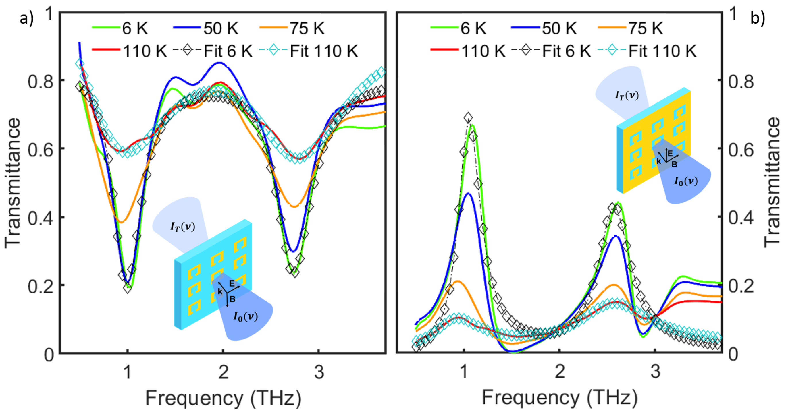
As previously mentioned, normal-incidence transmittance measurements were performed on both direct and complementary SRRs in the range of 0.5 to 4 THz at different temperatures, ranging from 6 K to 110 K and crossing Tc. For each temperature, the transmittance was normalized with respect to that of the bare Al2O3 substrate, to isolate the SRR contribution. Figure 2 shows the normalized transmittance for both direct and complementary devices at four different temperatures. The fitting curves (empty symbols) at 6 K and 110 K are shown as well. More specifically, Figure 2a reports the transmittance spectra for the direct device, with the electric field polarized perpendicular to the SRR gap, and Figure 2b for the complementary one, with the electric field polarization rotated by 90°, as shown in the insets and in agreement with the Babinet principle [39,40]. Indeed, the latter implies that the transmittance of the two SRR arrays is complementary given a 90° rotation of the polarization between the two structures [37,38]. When the electric field is polarized perpendicular to the SRR gap (for the direct case), two main resonances appear. The one at lower frequency (located at about 1 THz) is called LC resonance [41], since the electric field couples with the geometric capacitance and inductance of the SRR, generating a closed resonant circulating current inside the metallic ring. This resonance is also defined as “magnetic” because the time-varying current creates a magnetic dipole moment perpendicular to the ring plane. The second resonance, instead, appears at higher frequency (around 2.7 THz) and is called dipolar because it is characterized by the excitation of an electric dipole along the SRR arm opposite the gap. These features appear as dips in the direct device and as peaks in the complementary one, and become broader and weaker for increasing temperature.
The transmittance T d i r ( ν , T ) of the direct array (complementary, T c o m p ( ν , T ) = 1 − T d i r ( ν , T ) ) can be expressed through the following equation, already used in Reference [42] and here properly modified to take into account LC and dipolar resonance contributions simultaneously:
T d i r ( ν , T ) = T 0 1 + ( 1 + β L C 2 ) 2 Q L , L C 2 ( ν ν L C ν L C ν ) 2 1 + Q L , L C 2 ( ν ν L C ν L C ν ) 2 1 + ( 1 + β D i p 2 ) 2 Q L , D i p 2 ( ν ν D i p ν D i p ν ) 2 1 + Q L , D i p 2 ( ν ν D i p ν D i p ν ) 2
where T 0 is the transmittance level far from the resonances, ν r e s ( r e s = LC, Dip) is the resonance frequency, Q L , r e s = ν r e s Γ r e s is the loaded quality factor, Γ r e s being the resonance width, and β r e s is the coupling coefficient among different resonators. Since the equation is written in a product form, it is still valid when one of the two resonances is absent, with its corresponding term in the product going to 1. This equation, usually used in the microwaves region [42], takes into account both the resonating behavior of the single split-rings and their mutual interaction through the β coefficients.
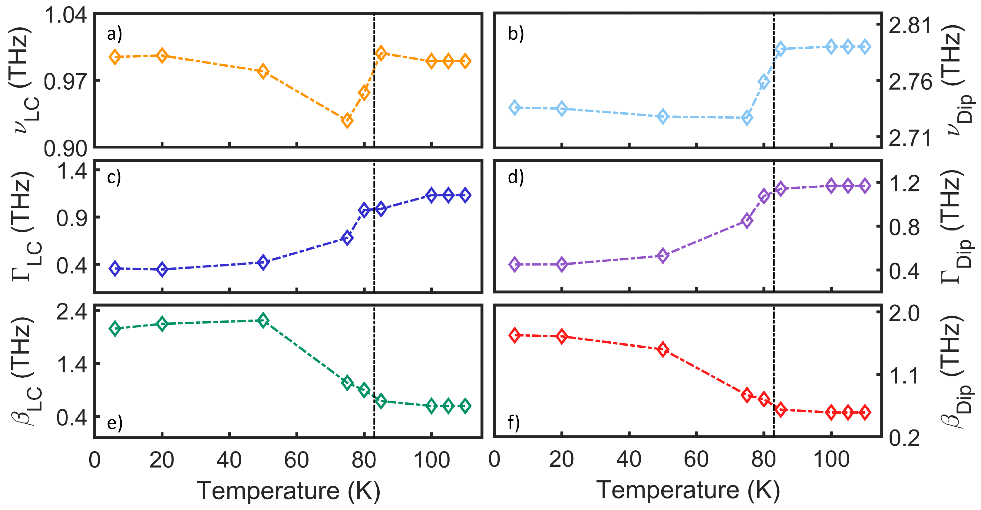
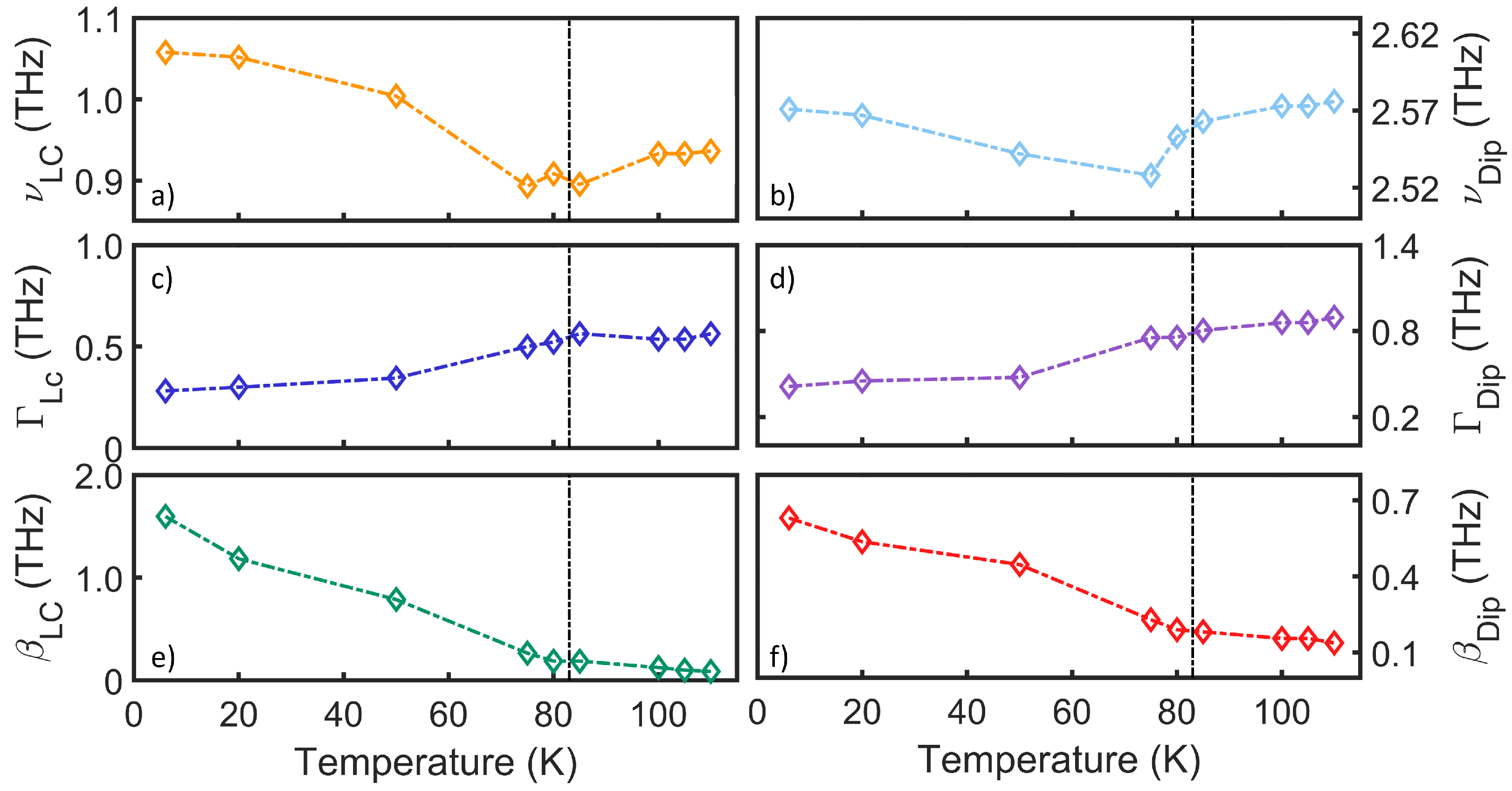
Equation (1) was employed to fit experimental transmittance data, as shown for two representative temperatures (6 and 110 K) in Figure 2a,b by open symbols. From the fitting, we extracted the temperature dependence of ν r e s , Γ r e s , and β r e s , which are represented in Figure 3 and Figure 4 for the direct and complementary array, respectively. All the parameters exhibit a variation in temperature. More in detail, for the direct SRR array, both the LC and dipolar resonance frequencies display a nonmonotonic behavior with temperature with a dip slightly below Tc (black vertical point-dashed line), corresponding to a redshift of 8% and 2% for the LC and dipolar resonance frequencies, respectively. The smaller redshift of the dipolar resonance frequency is due to its proximity to the YBCO superconducting gap. Indeed, by approaching the superconducting gap, the optical conductivity (real and imaginary part) of a superconductor is progressively less affected by the superconducting transition. The line width for both resonances exhibits a step-like behavior: from 110 K until 6 K, the line width of both LC and dipolar resonances decreases by a factor of ≃3, improving resonance selectivity. Finally, the coupling coefficient among different resonators ( β ) shows a robust increasing behavior while moving from the normal to the superconducting phase. In particular, for both resonances, β is nearly zero above Tc, when the material is not superconductive, indicating that each SRR of the system resonates individually, i.e., there is a negligible interaction among split-ring resonators. This interaction strongly increases in the superconducting state, where electrical properties are improved, and the positive sign of both β indicates that both the electric and magnetic fields are involved in the resonator coupling, as explained in [43].
In the complementary SRR device, a similar trend is observed for all the parameters. A modulation of 18% and of 2% for the LC and dipolar resonance frequencies is observed, respectively. Similarly to the case of the direct device, the line width for both resonances decreases by a factor of ≃2. Finally, the coupling coefficient β changes by a factor of 18 for the LC resonance, and by a factor of 5 for the dipolar one. Table A1 and Table A2 report the loaded quality factors of both LC and dipolar resonances for direct and complementary devices as a function of temperature. For both devices, the dipolar resonance has a higher quality factor than the LC one, and for both the resonances the quality factors increase by reducing temperature due to the reduction of ohmic losses.
We can compare our results with the ones obtained in the work by Thomas Cai Tan et al. [44], where they obtained, with a direct gold SRR array (40 μm periodicity), a Q factor for the LC (dipolar) resonance of Q = 2.2 (1.1). In our YBCO system, although its DC resistivity at 300 K (normal phase) is about 1000 μcm, i.e., nearly a factor of 500 higher than that of gold (∼2 μcm), below Tc we obtained a Q factor of the LC resonance of Q = 2.8 and Q = 6 for the dipolar one.
In light of the aforementioned results, kinetic inductance of the SRR arrays can be calculated to understand how the onset of the superconducting state affects the metamaterial optical response. This parameter can be obtained from the relation L k ( p / w ) ( X s / 2 π ν ) , where p is the SRR perimeter, w its width, Xs the surface reactance, i.e., the imaginary part of the surface impedance Zs, and ν the frequency [45].
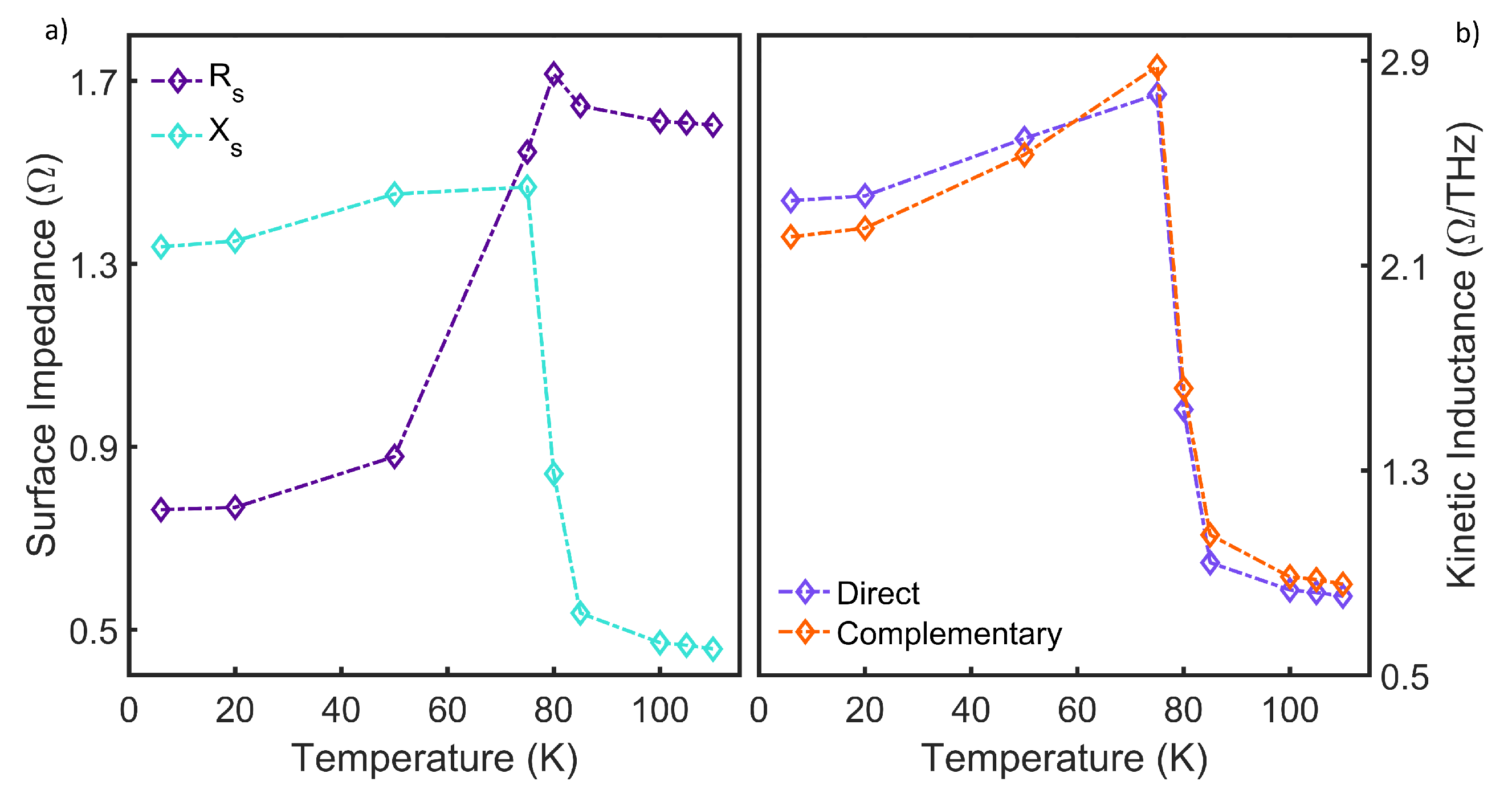
Being a property of the YBCO film, the surface impedance was extracted from the complex optical conductivity as measured in an unpatterned YBCO film at a fixed frequency ν = 0.8 THz, close to the LC resonance frequency of the metamaterial [46,47,48]. This is possible by approximating the unpatterned film as a lumped impedance in an equivalent transmission line model, as shown by Chen et al. [45]. The real part of the surface impedance determines the power absorption in a metal, caused by nonsuperconducting carriers, while the imaginary part accounts for the phase difference between incident electric field and the induced current density in the material, and is largely determined by superconducting Cooper pairs [25]. In the superconducting state, Xs dominates over Rs, whereas in the normal state, the opposite holds. Figure 5 reports the real and imaginary parts of the surface impedance (a) as a function of temperature at a fixed frequency ν = 0.8 THz, and the kinetic inductance as a function of temperature for both direct and complementary SRRs calculated at the LC resonance frequencies (values showed in Figure 3a and Figure 4a,b).
The slight difference in the kinetic inductance values of the two devices is ascribed to the slight change between the LC resonance frequency values of the two arrays. As can be noticed, the kinetic inductance has a maximum near Tc, directly affecting the strong variation of both LC and dipolar resonance frequencies around this temperature. Indeed, in a first approximation, ν r e s = 1 / 2 π ( L g + L k ) C , where C, Lg, and Lk are the capacitance, the geometric, and the kinetic inductance of the resonators. Therefore, the maximum in Figure 5b explains the minimum of the LC and dipolar resonance frequencies around Tc. This trend was already observed in other superconducting metamaterials, as described in Reference [28].

4. Conclusions

In this work, we demonstrated that a high-Tc YBa2Cu3O7 superconductor can be employed to tune the split-ring resonator optical response in the terahertz spectral range by crossing the critical temperature of the superconductor. Interpreting SRRs as RLC circuits, we demonstrated that for T < Tc, the inductive response (Xs) of the circuit dominates over the resistive one (Rs), inducing a modulation of the optical response of both direct and complementary devices. More specifically, the reduction of ohmic losses due to the superconducting transition makes LC and dipolar resonances stronger, with smaller line widths and larger coupling coefficients. Moreover, the strong increase of the kinetic energy, and therefore of the kinetic inductance Lk, in the superconducting state introduces a huge modulation of the resonances. Different superconducting metamaterial geometries, including fractal [49] and magnetic field enhancing shapes [50], will be investigated in the future to further study their use for opto-electronic applications.

Author Contributions

All authors contributed extensively to the work presented in this paper. S.M. and S.L. designed the experiment. S.L., S.M. and M.C.P. supervised the work. A.D.G. prepared the films and fabricated the SRR patterning. M.C.P. and S.M. developed the theoretical model. S.M., M.C.P., A.D. and L.T. performed the optical measurements and created SEM images. M.C.P. analyzed the data. S.M., M.C.P. and S.L. prepared the original draft. All authors reviewed the manuscript. All authors have read and agreed to the published version of the manuscript.

Funding

This work received financial support from the INFN institute in the framework of the projects of major relevance IMPACT, TERA and PbT.

Institutional Review Board Statement

Not applicable.

Informed Consent Statement

Not applicable.

Data Availability Statement

The datasets generated and analyzed during the current study are not publicly available due to Department policy but are available from the corresponding author on reasonable request.

Conflicts of Interest

The authors declare no conflict of interest.

Appendix A

LC and Dipolar Resonances Quality Factors

In the following, the loaded quality factors associated with both LC and dipolar resonances of direct and complementary devices as a function of temperature are reported.
Table A1. Loaded quality factors associated with both LC and dipolar resonances for direct device at different temperatures.
Temperature (K)QL,LCQL,Dip
6 K2.796.05
20 K2.876.05
50 K2.325.14
75 K1.363.20
80 K0.982.57
85 K1.012.45
100 K0.882.39
105 K0.882.39
110 K0.882.39
Table A2. Loaded quality factors associated with both LC and dipolar resonances for complementary device at different temperatures.
Temperature (K)QL,LCQL,Dip
6 K3.756.23
20 K3.515.69
50 K2.915.34
75 K1.793.36
80 K1.743.38
85 K1.593.19
100 K1.743.00
105 K1.743.00
110 K1.672.89

References

  1. Bilotti, F.; Sevgi, L. Metamaterials: Definitions, Properties, Applications, and FDTD-Based Modeling and Simulation. Int. J. RF Microw. Comput.-Aided Eng. 2012, 22, 422–438. [Google Scholar] [CrossRef]
  2. Liu, Y.; Zhang, X. Metamaterials: A new frontier of science and technology. Chem. Soc. Ref. 2011, 40, 2494–2507. [Google Scholar] [CrossRef] [PubMed]
  3. Capolino, F. Theory and Phenomena of Metamaterials, 3rd ed.; CRC Press: New York, NY, USA, 2009. [Google Scholar]
  4. Johnson, N.P.; Khokhar, A.Z.; Chong, H.M.; De La Rue, R.M.; Antosiewicz, T.J.; Mcmeekin, S. A Review of Size and geometrical Factors influencing resonant Frequencies in Metamaterials. Opto-Electron. Rev. 2006, 14, 187–191. [Google Scholar] [CrossRef] [Green Version]
  5. Di Pietro, P.; Adhlakha, N.; Piccirilli, F.; Di Gaspare, A.; Moon, J.; Oh, S.; Di Mitri, S.; Spampinati, S.; Perucchi, A.; Lupi, S. Terahertz Tuning of Dirac Plasmons in Bi2Se3 Topological Insulator. Phys. Rev. Lett. 2020, 124, 226403. [Google Scholar] [CrossRef] [PubMed]
  6. D’Apuzzo, F.; Piacenti, A.R.; Giorgianni, F.; Autore, M.; Cestelli Guidi, M.; Marcelli, A.; Schade, U.; Ito, Y.; Chen, M.; Lupi, S. Terahertz and mid-infrared plasmons in three-dimensional nanoporous graphene. Nat. Commun. 2017, 8, 14885. [Google Scholar] [CrossRef] [Green Version]
  7. Giorgianni, F.; Chiadroni, E.; Rovere, A.; Cestelli-Guidi, M.; Perucchi, A.; Bellaveglia, M.; Castellano, M.; Di Giovenale, D.; Di Pirro, G.; Ferrario, M.; et al. Strong nonlinear terahertz response induced by Dirac surface states in Bi2Se3 topological insulator. Nat. Commun. 2016, 7, 11421. [Google Scholar] [CrossRef] [Green Version]
  8. Limaj, O.; Giorgianni, F.; Di Gaspare, A.; Giliberti, V.; de Marzi, G.; Roy, P.; Ortolani, M.; Xi, X.; Cunnane, D.; Lupi, S. Observation of Dirac plasmons in a topological insulator. ACS Photonics 2014, 7, 556–560. [Google Scholar]
  9. Di Pietro, P.; Ortolani, M.; Limaj, O.; Di Gaspare, A.; Giliberti, V.; Giorgianni, F.; Brahlek, M.; Bansal, N.; Koirala, N.; Oh, S.; et al. Observation of Dirac plasmons in a topological insulator. Nat. Nanotech. 2013, 8, 556–560. [Google Scholar] [CrossRef] [PubMed] [Green Version]
  10. Haxha, S.; AbdelMalek, F.; Ouerghi, F.; Charlton, M.D.B.; Aggoun, A.; Fang, X. Metamaterial Superlenses Operating at Visible Wavelength for Imaging Applications. Sci. Rep. 2018, 8, 16119. [Google Scholar] [CrossRef] [Green Version]
  11. Yang, J.J.; Huang, M.; Tang, H.; Zeng, J.; Dong, L. Metamaterial Sensors. Int. J. Antennas Propag. 2013, 2013, 637270. [Google Scholar] [CrossRef] [Green Version]
  12. Macis, S.; Tomarchio, L.; Tofani, S.; Piccirilli, F.; Zacchigna, M.; Aglieri, V.; Toma, A.; Rimal, G.; Oh, S.; Lupi, S. Infrared plasmons in ultrahigh conductive PdCoO2 metallic oxide. Commun. Phys. 2022, 5, 145. [Google Scholar] [CrossRef]
  13. Qin, M.; Pan, C.; Chen, Y.; Ma, Q.; Liu, S.; Wu, E.; Wu, B. Electromagnetically Induced Transparency in All-Dielectric U-Shaped Silicon Metamaterials. Appl. Sci. 2018, 8, 10. [Google Scholar] [CrossRef] [Green Version]
  14. Oh, S.S.; Hess, O. Chiral metamaterials: Enhancement and control of optical activity and circular dichroism. Nano Converg. 2015, 2, 24. [Google Scholar] [CrossRef] [PubMed] [Green Version]
  15. Gil, M.; Bonache, J.; Martín, F. Metamaterial filters: A review. Int. J. Antennas Propag. 2008, 4, 186–197. [Google Scholar] [CrossRef]
  16. Dong, Y.; Yu, D.; Li, G.; Lin, M.; Bian, L.-A. Terahertz Metamaterial Modulator Based on Phase Change Material VO2. Symmetry 2021, 13, 2230. [Google Scholar] [CrossRef]
  17. Anlage, S.M. The physics and applications of superconducting metamaterials. J. Opt. 2011, 13, 024001. [Google Scholar] [CrossRef] [Green Version]
  18. Jung, P.; Ustinov, A.V.; Anlage, S.M. Progress in superconducting metamaterials. Supercond. Sci. Technol. 2014, 27, 073001. [Google Scholar] [CrossRef]
  19. Paulillo, B.; Manceau, J.M.; Li, L.H.; Davies, A.G.; Linfield, E.H.; Colombelli, R. Room temperature strong light-matter coupling in three dimensional terahertz meta-atoms. Appl. Phys. Lett. 2016, 108, 101101. [Google Scholar] [CrossRef]
  20. Singh, R.; Zheludev, N. Materials: Superconductor photonics. Nature Photonics. Nat. Photonics 2014, 8, 679–680. [Google Scholar] [CrossRef]
  21. Kalhor, S.; Kindness, S.J.; Wallis, R.; Beere, H.E.; Ghanaatshoar, M.; Degl’Innocenti, R.; Kelly, M.J.; Hofmann, S.; Joyce, H.J.; Ritchie, D.A.; et al. Active Terahertz Modulator and Slow Light Metamaterial Devices with Hybrid Graphene–Superconductor Photonic Integrated Circuits. Nanomaterials 2021, 11, 2999. [Google Scholar] [CrossRef] [PubMed]
  22. Keller, J.; Scalari, G.; Appugliese, F.; Mavrona, E.; Rajabali, S.; Süess, M.J.; Beck, M.; Faist, J. High Tc Superconducting THz Metamaterial for Ultrastrong Coupling in a Magnetic Field. ACS Photonics 2018, 5, 3977–3983. [Google Scholar] [CrossRef]
  23. Kurter, C.; Tassin, P.; Zhang, L.; Koschny, T.; Zhuravel, A.P.; Ustinov, A.V.; Anlage, S.M.; Soukoulis, C.M. Classical Analogue of Electromagnetically Induced Transparency with a Metal-Superconductor Hybrid Metamaterial. Phys. Rev. Lett. 2011, 107, 043901. [Google Scholar] [CrossRef] [PubMed] [Green Version]
  24. Duan, S.; Wu, J.; Shen, Z.; Guan, Y.; Jia, X.; Zhang, C.; Jin, B.; Kang, L.; Xu, W.; Wang, H.; et al. Tunable and high quality factor Fano and toroidal dipole resonances in terahertz superconducting metamaterials. Mater. Res. Express 2020, 7, 046001. [Google Scholar] [CrossRef]
  25. Dressel, M.; Grüner, G. Electrodynamics of Solids; Cambridge University Press: Cambridge, UK, 2002; pp. 28–30, 42–44, 372–377. [Google Scholar]
  26. Padilla, W.J.; Taylor, A.J.; Highstrete, C.; Lee, M.; Averitt, R.D. Dynamical Electric and Magnetic Metamaterial Response at Terahertz Frequencies. Phys. Rev. Let. 2006, 96, 107401. [Google Scholar] [CrossRef]
  27. Lobo, R.P.S.M.; Bontemps, N.; Racah, D.; Deutscher, G. Pseudo-gap and superconducting condensate energies in the infrared spectra of Pr-doped YBa2Cu3O7. EPL 2001, 55, 854–860. [Google Scholar] [CrossRef]
  28. Limaj, O.; Giorgianni, F.; Di Gaspare, A.; Giliberti, V.; de Marzi, G.; Roy, P.; Ortolani, M.; Xi, X.; Cunnane, D.; Lupi, S. Superconductivity-Induced Transparency in Terahertz Metamaterials. ACS Photonics 2014, 1, 570–575. [Google Scholar] [CrossRef]
  29. Lupi, S.; Irizawa, A.; Marcelli, A. THz: Research Frontiers for New Sources, Imaging and Other Advanced Technologies; MDPI: Basel, Switzerland, 2021; ISBN 978-3-0365-2163-3. [Google Scholar]
  30. Welp, U.; Kadowaki, K.; Kleiner, R. Superconducting emitters of THz radiation. Nat. Photonics 2013, 7, 702–710. [Google Scholar] [CrossRef]
  31. Delfanazari, K.; Asai, H.; Tsujimoto, M.; Kashiwagi, T.; Kitamura, T.; Yamamoto, T.; Sawamura, M.; Ishida, K.; Watanabe, C.; Sekimoto, S.; et al. Tunable terahertz emission from the intrinsic Josephson junctions in acute isosceles triangular Bi2Sr2CaCu2O8+d mesas. Opt. Express 2013, 21, 2171–2184. [Google Scholar] [CrossRef]
  32. Cao, W.; Singh, R.; Zhang, C.; Han, J.; Tonouchi, M.; Zhang, W. Plasmon-induced transparency in metamaterials: Active near field coupling between bright superconducting and dark metallic mode resonators. Appl. Phys. Lett. 2013, 103, 101106. [Google Scholar] [CrossRef] [Green Version]
  33. Zhang, Y.; Li, C.; Tu, X. Tuning Electromagnetically Induced Transparency of Superconducting Metamaterial Analyzed with Equivalent Circuit Approach. Prog. Electrom. Res. M 2020, 91, 29–37. [Google Scholar] [CrossRef]
  34. Li, C.; Wu, J.; Jiang, S.; Su, R.; Zhang, C.; Jiang, C.; Zhou, G.; Jin, B.; Kang, L.; Xu, W.; et al. Electrical dynamic modulation of THz radiation based on superconducting metamaterials. Appl. Phys. Lett. 2017, 111, 092601. [Google Scholar] [CrossRef]
  35. García-García, J.; Martín, F.; Baena, J.D.; Marqués, R.; Jelinek, L. On the resonances and polarizabilities of split ring resonators. J. Appl. Phys. 2005, 98, 033103. [Google Scholar] [CrossRef]
  36. Bitzer, A.; Merbold, H.; Thoman, A.; Feurer, T.; Helm, H.; Walther, M. Terahertz Near-Field Imaging of Electric and Magnetic Resonances of a Planar Metamaterial. Opt. Express 2009, 17, 3826–3834. [Google Scholar] [CrossRef]
  37. Totzeck, M.; Krumbügel, M.A. Extension of Babinet’s principle and the Andrews boundary diffraction wave to weak phase objects. J. Opt. Soc. Am. A 1994, 11, 3235–3240. [Google Scholar] [CrossRef]
  38. Ortiz, J.D.; del Risco, J.P.; Baena, J.D.; Marqués, R. Extension of Babinet’s principle for plasmonic metasurfaces. Appl. Phys. Lett. 2021, 119, 161103. [Google Scholar] [CrossRef]
  39. Bitzer, A.; Ortner, A.; Merbold, H.; Feurer, T.; Walther, M. Terahertz Near-Field Microscopy of Complementary Planar Metamaterials: Babinet’s Principle. Opt. Express 2011, 19, 2537–2545. [Google Scholar] [CrossRef] [PubMed]
  40. Falcone, F.; Lopetegi, T.; Laso, M.; Baena, J.D.; Bonache, J.; Beruete, M.; Marqués, R.; Martín, F.; Sorolla, M. Babinet Principle Applied to the Design of Metasurfaces and Metamaterials. Phys. Rev. Lett. 2004, 93, 197401. [Google Scholar] [CrossRef] [PubMed] [Green Version]
  41. Klein, M.W.; Enkrich, C.; Wegener, M.; Soukoulis, C.M.; Linden, S. Single-slit split-ring resonators at optical frequencies: Limits of size scaling. Opt. Lett. 2006, 31, 1259–1261. [Google Scholar] [CrossRef] [Green Version]
  42. Jin, B.; Zhang, C.; Engelbrecht, S.; Pimenov, A.; Wu, J.; Xu, Q.; Cao, C.; Chen, J.; Xu, W.; Kang, L.; et al. Low Loss and Magnetic Field-Tuned Superconducting THz Metamaterial; Optical Society of America: Washington, DC, USA, 2010. [Google Scholar]
  43. Garcia-Garcia, J.; Bonache, J.; Gil, I.; Martin, F.; Velazquez-Ahumada, M.C.; Martel, J. Miniaturized microstrip and CPW filters using coupled metamaterial resonators. IEEE Trans. Microw. Theory. Tech. 2006, 54, 2628–2635. [Google Scholar] [CrossRef]
  44. Tan, T.C.; Plum, E.; Singh, R. Surface Lattice Resonances in THz Metamaterials. Photonics 2019, 6, 75. [Google Scholar] [CrossRef] [Green Version]
  45. Chen, H.-T.; Yang, H.; Singh, R.; O’Hara, J.F.; Azad, A.K.; Trugman, S.A.; Jia, Q.X.; Taylor, A.J. Tuning the Resonance in High-Temperature Superconducting Terahertz Metamaterials. Phys. Rev. Lett. 2010, 105, 247402. [Google Scholar] [CrossRef] [PubMed]
  46. Kiwa, T.; Tonouchi, M. High frequency properties of YBCO thin films diagnosed by time-domain terahertz spectroscopy. Phys. C 2001, 362, 314–318. [Google Scholar] [CrossRef]
  47. Klein, N. High-frequency applications of high-temperature superconductor thin films. Rep. Prog. Phys. 2002, 65, 1387–1425. [Google Scholar] [CrossRef]
  48. Gao, F.; Whitaker, J.F.; Uher, C. High-Frequency Surface Impedance and Penetration Depth of YBa2Cu307 Films: Coherent Time-Domain Spectroscopy Method. IEEE Trans. Appl. Supercond. 1995, 5, 2. [Google Scholar] [CrossRef]
  49. Wallace, G.Q.; Lagugné-Labarthet, F. Advancements in fractal plasmonics: Structures, optical properties, and applications. Analyst 2019, 144, 13–30. [Google Scholar] [CrossRef]
  50. Panaro, S.; Nazir, A.; Proietti Zaccaria, R.; Razzari, L.; Liberale, C.; De Angelis, F.; Toma, A. Plasmonic Moon: A Fano-Like Approach for Squeezing the Magnetic Field in the Infrared. Nano Lett. 2015, 15, 6128–6134. [Google Scholar] [CrossRef]
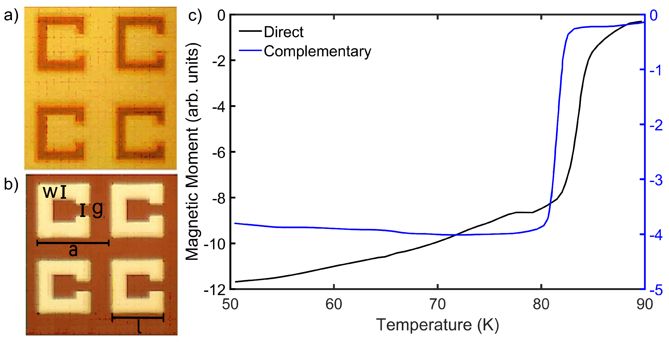
Figure 1. SEM pictures of the direct (a) and complementary (b) SRR devices. Dark areas mark YBCO film, while light areas mark Al2O3 substrate. The geometrical details are l = 20 μm, g = 5 μm, w = 5 μm, and a = 30 μm. (c) Magnetic moment measurements for the direct and the complementary device, respectively.
Applsci 12 10242 g001
Figure 2. Experimental transmittance spectra for direct (a) and complementary (b) SRR arrays at different temperatures. In both cases, the fitting curves (empty symbols) at 6 K and 110 K are reported, too. The insets show a sketch of the optical measurement configuration for direct (a) and complementary (b) SRR arrays with the corresponding electric field polarization: perpendicular with respect to the SRR gap (a), and parallel with respect to the complementary SRR gap (b). Yellow areas indicate YBCO, and light-blue areas indicate Al2O3 substrate. I 0 ( ν ) indicates the incoming radiation, whereas I T ( ν ) indicates the transmitted one.
Applsci 12 10242 g002
Figure 3. Fitting results (empty symbols) for the direct SRR device vs. T, as obtained by using Equation (1) applied to data in Figure 2a. The dashed color lines are a guide for the eyes. Error bars correspond to the size of diamond symbols. Panels (a,c,e) show the resonance frequency ν L C , the line width Γ L C , and the coupling coefficient β L C of the LC resonance; (b,d,f) show the the same quantities for the dipolar resonance. The black vertical point-dashed lines underline the YBCO critical temperature Tc = 83 K.
Applsci 12 10242 g003
Figure 4. Fitting results (empty symbols) for the complementary SRR device vs. T, as obtained applying Equation (1) to data in Figure 2b. The dashed color lines are a guide for the eyes. Error bars correspond to the size of diamond symbols. Panels (a,c,e) show the resonance frequency ν L C , the line width Γ L C , and the coupling coefficient β L C of the LC resonance; (b,d,f) show the same quantities for the dipolar resonance. The black vertical point-dashed lines underline the YBCO critical temperature Tc = 81 K.
Applsci 12 10242 g004
Figure 5. (a) Surface resistance (Rs) and reactance (Xs) associated with the unpatterned YBCO film as a function of temperature. The complex quantity was calculated by using experimental complex conductivity of the unpatterned YBCO film at a fixed frequency ν = 0.8 THz, around the LC resonance frequency of the metamaterial. (b) Kinetic inductance calculated at the LC resonance frequency, whose values are depicted in Figure 3a and Figure 4a, as a function of temperature for both direct and complementary devices.
Applsci 12 10242 g005
Publisher’s Note: MDPI stays neutral with regard to jurisdictional claims in published maps and institutional affiliations.