Article

Experience in Researching and Designing an Innovative Way of Operating Combined Building–Energy Systems Using Renewable Energy Sources

Faculty of Civil Engineering, Slovak University of Technology, Radlinského 11, 81005 Bratislava, Slovakia
*
Author to whom correspondence should be addressed.
Appl. Sci. 2022, 12(20), 10214; https://doi.org/10.3390/app122010214
Submission received: 13 July 2022 / Revised: 27 September 2022 / Accepted: 7 October 2022 / Published: 11 October 2022
(This article belongs to the Special Issue Sustainable Design under Climate Responsive Environments)

Abstract

:
This study describes our experience in researching and designing an innovative way of operating combined building–energy systems using renewable energy sources. We used the concepts of the ISOMAX integrated building–energy system’s patented technical solution, which we have long been exploring and have developed various novel and original solutions, as inspiration for our research. A consistent peak heat/cooling supply is a key component of the patented ISOMAX system, which has also been proven in its use in many buildings. Energy systems are no longer dependent on unreliable, unpredictable, and hard-to-forecast geothermal and solar energy because of the peak energy source. We had to improve the original design to guarantee the efficient, comfortable, and dependable operation of all the energy systems in the building. We increased the capacity of the ventilation system by including a peak heat/cooling source, a short-term heat/cooling storage tank, and the option of using an air handling unit with heat recovery or a water/air heat exchanger. The addition of terminal elements for heating, cooling, and ventilation systems was also made, along with including a solar system, a wind turbine, and the potential for waste heat recovery. Our study led to the creation of a unique operating model that, with the building management system, optimizes all of the energy systems and heating/cooling sources. The utility model SK 5749 Y1 analyzes the various alternatives in great detail.

1. Introduction

We have focused our extensive research on the creation and innovation of coupled building–energy systems employing renewable energy sources (RES) since about 2004. The building technology with the name and trademark ®ISOMAX inspired us (hereinafter referred to as the “ISOMAX system” or “ISOMAX”), patent SK 284 751, author: KRECKÉ [1]. This system uses solar energy that the energy roof collects and stores in a long-term ground-heat storage beneath or close to the structure. A thermal barrier is formed by pipes embedded in the building envelope that use heat from the ground heat storage or ground cold from the building surroundings to eliminate heat losses. We describe the operation of this system in more detail in Section 2.
Constructing buildings using this system clarifies that a reliable peak heat/cooling source is also required to free energy systems from reliance on erratic, unpredictable, and difficult-to-expect solar and geothermal energy stored in underground heat storage. For these reasons, our research goals and questions were how to address the identified shortcomings of this perspective system and ensure the reliable, cost-effective, and comfortable operation of the building’s energy systems using as much renewable energy as possible. Our research on combined building–energy systems has focused mainly on energy (solar) roofs, long-term heat storage, especially in ground heat storage, and active thermal protection. In Section 3, we present an overview of the research in the combined construction and energy systems field.
The originality of our research, as it is presented in this study, lies in the development of the ISOMAX system’s original mode of operation in various modes for various energy systems and in the addition of heat/cooling sources, as well as other system components, which, in coordination with the building control system, optimize the mode of operation and provide a variety of energy-secure and dependable technical solutions for buildings versus buildings with fossil fuel-based heat/cooling sources. For the combined building–energy sources of heat/cooling and energy systems, we have developed and specified new and original variants of operation, for which we have developed variants of wiring schemes (Section 4.1). In Section 4.2, we define and describe the specific technical solution of the energy systems’ wiring. We explain some of the results of our research in Section 4.3, including the specification of the integrated building–energy system’s mode of operation in two different modes, namely the active thermal protection mode (Section 4.3.1) and the heat-recovery ventilation mode (Section 4.3.2). In Section 4.4, we describe our proposal for the innovation of a pipe-in-pipe heat recovery system. In Section 5, we summarize the outcomes of our research and in Section 6 we define the objectives of our further research.

2. The Initial Technical Solution

In terms of the method of operation of the ISOMAX system [1], the primary heat sources are solar and geothermic energy (Figure 1). The hot water can be reheated using an electric or gas storage water-heater. The energy (solar) roof collects solar energy (ESR). It is only useful in the summer and to a limited extent during the transitional period with sufficient heating of the heat transfer medium, i. j., at a temperature higher than the temperature in the long-term ground-heat storage. This source results in unstable and insufficient absorption of solar radiation (GHS). A less significant amount of geothermic energy is also trapped in the GHS for use as heating. Without boosting energy efficiency using a peak heat source, such as a heat pump or solar collectors, the ISOMAX system [1] employs solar energy stored in the GHS exclusively for direct usage in the thermal barrier (TB) and for preheating hot water. Due to the numerous fluctuating physical parameters affecting the solar radiation ESR, which only acts to charge the long-term GHS, it is difficult to determine the exact quantity of energy. Heat sources—ESR and GHS—are difficult to regulate and cannot meet the sudden requirements to increase the heat supply for heating and hot water. Additionally, they cannot meet the yearly energy requirements for heating, hot water, or ventilation. The ISOMAX system’s source design [1] is typically implemented empirically through estimation [2].
By implementing a thermal barrier (TB) in the exterior structures to utilize the heat that is stored in the ground heat storage (GHS) or the cold that comes from registers of pipes buried close to the building below ground level at a depth of 1 to 2 m, the ISOMAX system eliminates heat loss/gain in the interior of the building (Figure 2) [1,2].
The thermal barrier is a network of pipes installed in the building structure between the static bearing and thermal insulation portions, as shown in Figure 3, or in the load-bearing portions of reinforced concrete panels that are divided into interior and exterior sides by thermal insulation, as shown in Figure 4. ISOMAX has technical solutions for applying both of the mentioned alternatives (Figure 5). For the production of self-supporting reinforced concrete panels, it applies lost formwork, and concrete pouring takes place directly on the construction site of the building (Figure 4) [1,2].
The patented ISOMAX system uses pipe-in-pipe heat recovery ventilation that is both outside and beneath the building for building ventilation, as shown in Figure 6 [1,2]. The ISOMAX control system is designed individually for each building (Figure 7) [1,2].

3. A Summary of the Research on Integrated Building and Energy Systems

As per the study of Ulbrich, Milaszewicz, and Rachel [3], 2007, “Note that, the use of solar energy in conjunction with near-surface geothermal energy combines the benefits of two proven processes—solar technology and the use of geothermal heat—in an amazingly simple form. Numerous instances from all climatic zones demonstrate the effectiveness of this technology, which is very cost-effective in terms of both manufacture and operation. Further study and improvement are required to optimize and be able to “compute” this building technology. Gaining control over the calculation of heat exchange processes and optimizing insulation thicknesses are the goals of additional research. The Isomax building technology, however, may already be used in an efficient and environmentally responsible manner thanks to prior expertise”.
As per the study of Guinea [4], 2008, “Reports that a graduate engineer and scientist from Luxembourg, E. KRECKÉ proposed two interesting ideas in his ISOMAX system. The first involves the creation of a temperature-controlled surface (thermal barrier) between two insulation layers in the building envelope. This efficiently uses subsurface temperatures that cannot be used directly for heating inside the building and effectively controls heat flow via the walls and roof covering. Thus, it is simple and effective to utilize the significant heat that builds up in our environment as “basement temperature” to reduce the transmission losses in the building envelope. The second idea involves the direct underground collection of solar energy and its selective storage in certain underground layers. This technique does not use conventional thermal solar panels collection but replaces them with a simple plastic pipe buried under the roof covering. In this case, the absorbed solar energy is used directly for storage in the soil without using the usually insulated water tanks. The storage capacity of a ground heat storage tank is determined by the specific heat capacity and the weight of the material used as a storage tank”.
As per the study of D.O. Rijksen [5], 2010, “This document presents general guidelines for the required cooling performance of an entire office building using thermally activated building systems (TABS). On-site measurements have been carried out to obtain the required cooling performance of the whole building and individual zones. In addition, the rooms’ indoor climatic conditions and the TABS’ surface temperatures were measured. The measured data were used to analyze the predictive performance of the simulation model. To obtain general guidelines for the required cooling performance of a standard office building, whole building simulations were used to determine the effect of variable internal heat gains and different window sizes”.
As per the study of Krzaczek and Kowalczuk [6], 2011, “Present a concept of an indirect heating and cooling technique of residential buildings driven by solar thermal radiation called Thermal Barrier (TB), which is composed of polypropylene U-pipes located inside of external walls. Fluid flows inside a U-pipe system with a variable mass flow rate and variable supply temperature. This creates a semi-surface parallel to wall surfaces and a spatially averaged temperature almost constant and close to the reference temperature of 17 °C all year round. The TB technique is used to stabilize and reduce heat flux normal to the wall surface and maintain its direction from internal air out to ambient air throughout the year. The main intention of this paper is to investigate the thermal performance and stability of the Thermal Barrier. A 3D FE model of a prefabricated external wall component containing a TB U-pipe system with flowing fluid is developed using the FE code of ABAQUS. A novel SVC control system supports the FE analysis implemented in FORTRAN to simulate real working conditions. The advantages of the TB heating/cooling technique are outlined”.
As per the study of Arteconi A. [7], 2014, “The purpose of this paper is to analyze the effect of demand-side control strategies on the performance of a thermally activated building system applied in a commercial building. The objective is to estimate the potential of TABS to shift the load demanded by the power system. The analysis is performed using a sample case: first, the existing TABS control strategy is analyzed and then the possible implementation of DSM mechanisms is analyzed. In particular, three different demand-side control mechanisms are evaluated: a peak shedding strategy, a random on/off system request, and a night load shifting strategy. The simulation results show the high potential of TABS in the DSM framework, as TABS enable load control while hardly affecting thermal comfort”.
As per the study of Lim Jae-Han [8], 2014, “This study aims to develop operational guidelines for TABS according to the heating and cooling load characteristics of a specific campus building. The load characteristics of the building were analyzed, then the load zones were defined according to the heating and cooling characteristics. At the same time, the thermal performance of TABS for heating and cooling with a range of supply water temperatures was calculated. Operating guidelines, classified according to the load zone, are proposed”.
As per the study of S.H. Park [9], 2014, “The objective of this study was to present a simulation study estimating the thermal comfort and energy consumption of a thermally activated building system (TABS) combined with radiant floor heating and a packaged air conditioning system in a conventional residential building. and a low-thermal loaded residential building. Two residential buildings with different shell types were modeled using EnergyPlus. This study combines the proposed TABS heating and cooling system with the existing one. The results indicate that TABS combined with the current system is thermally comfortable and energy-efficient, especially for buildings with low thermal loads”.
As per the study of Z.B. Liu [10], 2015, “Active Solar Thermoelectric Radiant Wall (ASTRW) system represents a new solar wall technology that uses solar energy to offset passive heat losses or gains through the building walls. Experiments have been conducted in different regimes. The results show that the ASTRW system can not only eliminate the conventional heat load on the building envelope but also provide thermal capacity for space heating”.
As per the study of Dai, Shang, XL Li, and SF Li [11], 2016, “A three-dimensional non-stationary model developed to study the heat transfer performance for a vertical U-tube ground heat exchanger (GHE) is investigated. The location of the transient heat transfer process analysis during short-term accumulation was between the inner and outer sides of the borehole. From its results, it can be concluded that the soil temperature field in the depth direction in the middle part is distributed in a “narrow belt shape”. For short-term heat accumulation, the thermal interference distance of the ground heat exchanger is 1.0 m in the radius, and the main heat transfer field is 0.4 m in the radius. The internal temperature field of the borehole is dominated by the inlet branch of the U-tube and becomes uniform due to the influence of the prolonged heat accumulation time. The temperature differential between the borehole wall and the surrounding soil is greater the longer the accumulation time is, compared to the temperature difference between the interior and outside of the borehole. In addition, the temperature difference between the fluid in the U-tube and the borehole wall decreases as the accumulation time increases. The unknown is the change in the temperature differential between the nearby and farther-off boundary soil”.
As per the study of C. Shen [12], 2017, “To reduce the heating energy consumption, air source heat pumps are proposed in this study to produce low-temperature hot water for the building envelope. A comprehensive numerical model is adopted to simulate the dynamic heat transfer in the duct-embedded structure, and the model has been verified by experiment. The proposed system is more suitable for cold areas because more heat transfer can be reduced there. The water temperature significantly affects the system performance and room temperature water is recommended. Overall, the proposed system is efficient as an auxiliary heating system”.
As per the study of Chung, Woong June [13], 2019, “This study proposes simple operator-level guidelines to enhance the practical use of TABS by considering the risk of condensation in hot and humid environments. Therefore, the weather conditions and characteristics of the TABS system were analyzed and possible simple solutions to avoid condensation were proposed. To apply both strategies, cooling operation guidelines were proposed with a simple calculation of the internal dew point temperature, which could prevent condensation at any time”.
As per the study of S. Chen [14], 2020, “A thermally activated phase change composite wall (TAPCW) concept is proposed to address the retrofitting issues faced by existing buildings, that is, to replace the interlayer embedded in the duct with an encapsulated PCM panel and relocate it to the exterior of the supporting layer. This work focuses on investigating the thermal and energy savings of TAPCW in the winter climate of northern China through a validated numerical model”.
As per the study of Kalús, Straková, and Kubica [15], 2021, “The study describes ITAP panels—as indoor thermally active panels with an integrated active surface in an innovative way that combines existing building and energy systems into one compact unit, thus creating combined building–energy systems. These are building structures with an internal energy source. The main benefit of ITAP panels is the possibility of unified and prefabricated production. At the same time, they represent a reduction of production costs due to their technological production process, a reduction of assembly costs due to a reduction of steps during implementation on the construction site, and a reduction of implementation time due to their application method”.
As per the study of Kalús, Cvíčela, Janík, and Kubica [16], 2021, “The paper presents that energy systems built into one of the building structures that serve to capture solar energy, geothermic energy, and ambient energy or that have the function of the end elements of the heating, cooling, and ventilation system are generally called combined building-energy systems. The paper presents a cross-section of our team’s research and scientific activities in the field of combined building-energy systems”.
As per the study of Kalús, Mučková, and Koudelková [17], 2021, “The study compares a classic perimeter cladding equipped with thermal insulation meeting the normative requirements for thermal resistance and a perimeter cladding with an integrated thermal barrier significantly eliminating the thickness of thermal insulation. We evaluate the use of the thermal barrier using: economic indicator one, where we compare the cost of heat delivered to the TB in a structure with significantly eliminated thermal insulation and the saved cost of thermal insulation at the standard thickness; economic indicator two, where we compare the cost of heat delivered to the TB in a structure with significantly eliminated thermal insulation with the potential gain from the sale of the useful area of the building gained compared to the area at the normative thickness of thermal insulation; and economic indicator three, where we compare the cost of heat delivered to the TB in a structure with significantly eliminated thermal insulation with the cost of grey energy at the normative thickness of thermal insulation. Based on a parametric study it can be concluded that TB shows a very promising and efficient solution in terms of the evaluation of economic indicators one to three, which are even more significant if we use heat for the TB from RES or waste heat”.
As per the study of Kalús, Janík, and Kubica [18], 2021, “Reports experiences with research on combined building-energy systems. The experimental house EB 2020 was primarily designed following the patented ISOMAX system (SK 284 751, author: Dipl.-Ing., Phys. Edmond D. KRECKÉ), which represents a high potential for the use of renewable energy sources. In the design of the experimental house EB2020, the problem of this system was eliminated by designing peak heat sources whose heat source is exclusively solar and geothermic energy. This paper describes the theoretical procedure for calculating the efficiency of an energy roof, a comparison with a conventional solar collector, experimental measurements of the energy roof during one season, and an evaluation of the measured data. To achieve a higher efficiency of the energy roof, it is advisable to consider installing a dark roof covering and installing multiple circuits with appropriate orientation according to cardinal directions. This can be the subject of further research”.
As per the study of Kalús, Janík, Koudelková, Mučková, and Sokol [19], 2022, “In this study, we describe our contribution to the research on GHS as part of building energy systems with RES. In our long-term research, since about 2004, the patented technical solution of the ISOMAX system has inspired us (by Edmond D. KRECKÉ). We summarize the novelty and originality of our research results in this field in three utility models and one European patent. The research and experimental measurements were carried out on the experimental house EB2020. In particular, we focused on quantifying the energy harvested from the ESR and the realistic possibility of long-term storage of this energy in the GHS. We investigated the possibility of using the stored heat for application in active thermal protection (ATP) in building envelopes for low-temperature radiant large-area heating and the function of the thermal barrier (TB). The experimental measurements were carried out during one charging season and one discharging season (one heating period). Based on the theoretical calculations’ analysis and experimental measurements’ results, the use of the accumulated heat in the GHS in the experimental house EB2020 is limited due to the composition of the building envelope. The use of heat in ATP represents a high potential of energy savings for the application as a TB function by significantly eliminating heat losses/gains. Based on these research results, it is possible to recommend the use of GHS in cooperation with ATP also in the heating/cooling function only for the building envelope, the load-bearing part of which is made of a material with high thermal conductivity, i.e., low thermal resistance, for example as reinforced concrete”.

4. Methodology

The following methodology was used in the study:
Analysis of the upgraded method of operation of combined building–energy systems, Section 4.1;
Building energy systems are analyzed, defined, the operation’s design, and a wiring diagram is created, Section 4.2;
Synthesis of the knowledge gained from the scientific analysis and transformation of the data into an innovative method of operation, Section 4.3;
Inductive and analogical form of creation innovative method of realization of ventilation with heat recovery pipe in pipe, Section 4.4.

4.1. Analysis of an Upgraded Method of Operation of Various Building–Energy Systems

From the implementation of buildings using the patented ISOMAX system, it is evident that a reliable peak heat/cooling source is also necessary so that the energy systems (heating, cooling, hot water, and ventilation) are not dependent on fluctuating, unstable, and hardly predictable solar and geothermic energy stored in large capacity heat reservoirs, especially in GHS and ground cooling circuits (Figure 8). In addition, the production of panels in the form of a lost formwork according to patent SK 284 751 (ISOMAX) was not successful, was too complicated, time-consuming, and often showed deficiencies from a static point of view [1,2].
For these reasons, we were required to develop the components which would be produced in a panel plant, and only after testing the functionality of individual panels, would they be shipped to the construction site. A high level of energy efficiency and economic efficiency was also to be achieved, and RES was to be used as much as possible from an environmental point of view.
In the development of innovative solutions for building components with built-in energy-active elements, we have based our approach on the ISOMAX system [1], which uses an energy (solar) roof, a ground heat storage applied for active thermal protection in the building envelope in the function of a thermal barrier, and uses a duct in a pipe located in the ground for ventilation with heat recovery.
We had to improve the original plan to guarantee the efficient, comfortable, and dependable operation of all of the energy systems in the building. We added a peak heat/cooling source, a short-term heat/cooling storage tank, and the option of using an air handling unit with heat recovery or adding a water/air heat exchanger to heat and cool the air for ventilation. Additionally, we have included terminal elements for heating, cooling, and ventilation systems, a solar system, a wind turbine, the potential for waste heat recovery, and more (Figure 8). We have proposed examples of technically innovative solutions of operation modes with complex functional measurement and control schemes in different variants for individual ways of operation of power systems. All energy systems are involved in the schemes, which optimize the building operation modes by employing synergy with the building control system. These schemes are suitable for buildings that use combined systems and energy systems. Variant solutions are analyzed in detail in the utility model SK 5749 Y1 [20].

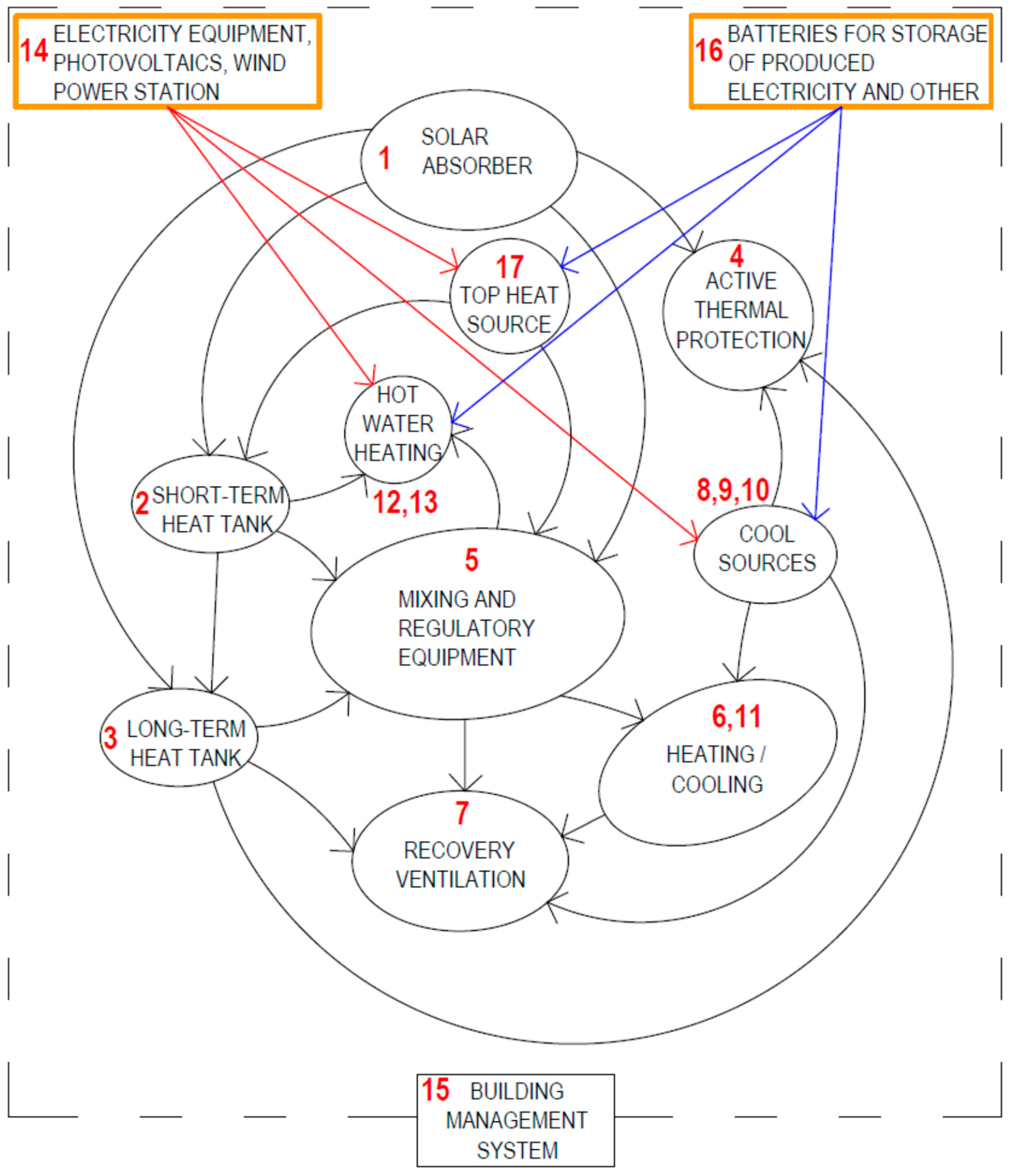
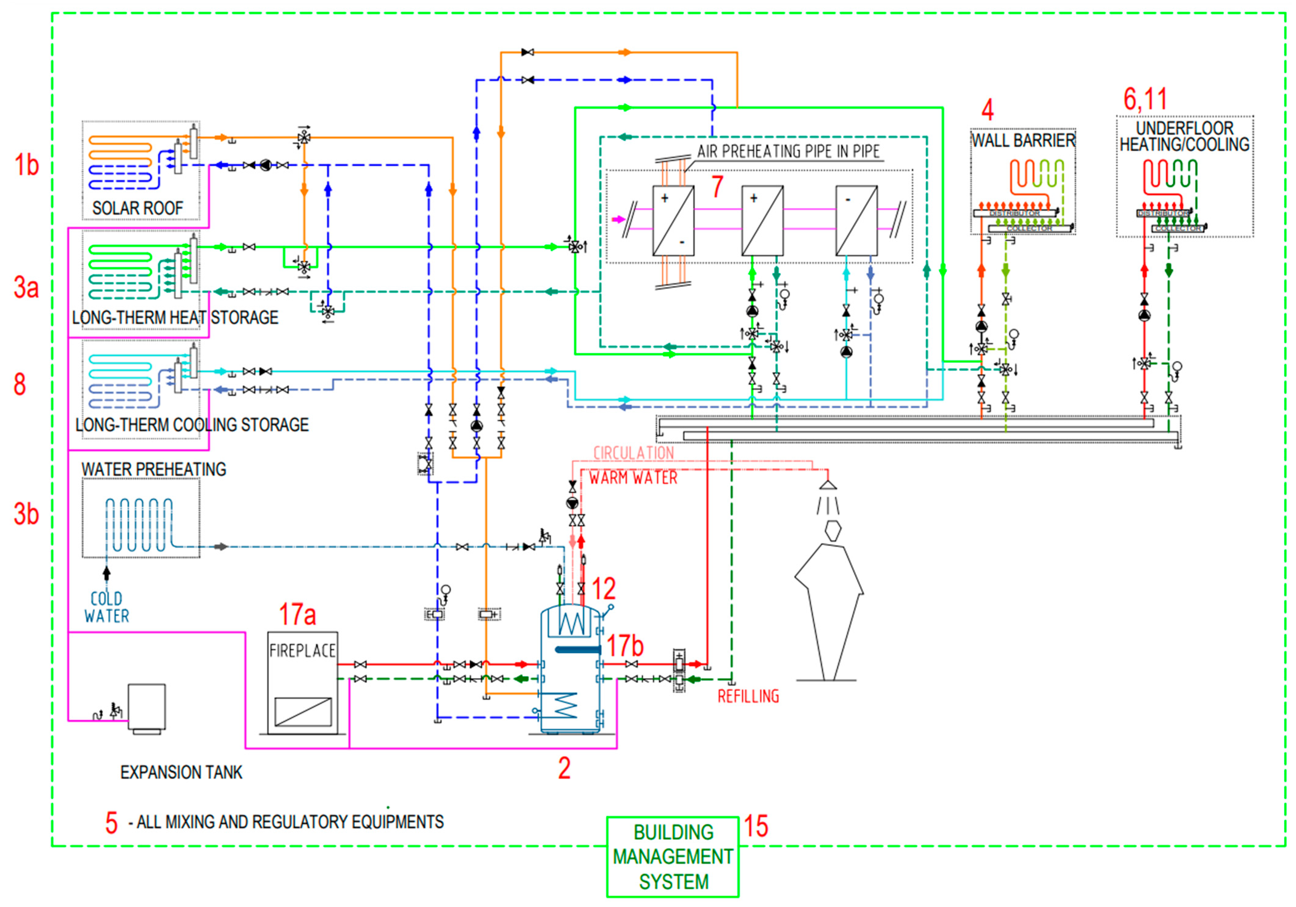
4.2. Analysis, Defining, Designing the Method of Operation, and Creating a Wiring Diagram of the Combined Building–Energy Systems

Solar energy absorbed by the energy roof “1” and stored in a medium temperature ground-heat storage “3” (GHS-MT), between 30 and 50 °C, serves as the heat source for heating, ventilation, and preheating hot water. As a peak heat source “17” to offset the heat losses, a fireplace with a hot-water heat exchanger and an electric heating insert is suggested. The fireplace hot-water heat exchanger is connected to a ground heat storage tank (long-term heat storage) “3“ and a heating water storage tank (short-term heat storage) “2“, Figure 9.
Underfloor heating circuits “6” make up the heating system, and thermal barriers “4” are built into the exterior perimeter walls. The peak heat source, a fireplace with a hot-water heat exchanger connected to the heating water storage tank “2”, which is furnished with an electric heating insert, is connected to the energy roof “1”, the ground heat storage tank “3” and the individual circuits via distributors and collectors. Any heat source at any time can provide the required heat for heating, as shown in Figure 9.
Counter-current heat recovery exchanger pipe-in-pipe (ISOMAX system) “7” is designed for the heat recovery ventilation of the building and is located partially outside the building at a depth of 2 m below ground level and partially directly under the building in the underground heat reservoir at a depth of 1 m below the building’s floor. A heat exchanger installed in the internal supply air duct is used to reheat or cool the air. The heat required to heat the ventilation air is supplied from the heating water storage tank “2“. The cooling required to cool the ventilation air is supplied from ground cooling circuits “8“—pipes laid at a depth of about 2 m below ground level outside the building (Figure 9).
A ground cooling circuit “8”, which consists of a network of 20 × 2 PP pipes buried 2 m beneath the ground outside the structure, is created to cool the building. This cooling system is linked, via a distributor and collector, to the thermal barrier circuits “4” in the perimeter external walls, which work to reduce the effect of irradiation (preheating the cooled walls in winter), as well as to the heat exchanger in the ductwork to cool the ventilation air “7”, Figure 9.
Hot water preparation is in two stages. The water in the ground heat storage tank “3” is preheated in the first step from a temperature of 10 °C to 25–30 °C. In the second step, the hot water is heated to the desired temperature of 55–60 °C in a trivalent heating water storage tank with an integrated hot water tank “2” utilizing solar energy, electricity, or hot water heated in a hot water heat exchanger in the fireplace “17”, Figure 9.

4.3. Synthesis of the Knowledge Gained from the Scientific Analysis and Transformation of the Data into an Innovative Method of Operation

In the following chapter, we describe a selection of outputs from our research, namely the definition of the mode of operation of the combined building–energy system in different modes of operation, namely in the active thermal protection mode (Section 4.3.1) and in the heat recovery ventilation mode (Section 4.3.2).
The new way of operating the combined building–energy system is described in Section 4.1 and Section 4.2, with which we have upgraded and supplemented the ISOMAX system [1]. It ensures the reliable, economical, and comfortable operation of the individual building energy systems and eliminates the risk of unstable, erratic, and unpredictable availability of solar energy. The addition of a peak heat/cooling source, a short-term heat/cooling storage, the potential use of a heat recovery air-handling unit or the addition of a water/air heat exchanger for heating and cooling ventilation air, a photovoltaic system, a wind power plant, the potential use of waste heat, as well as the addition of the end elements of the heating, cooling, and ventilation system are the foundations of the innovation, as shown in Figure 8.
We have designed and defined the way of operation of power systems in different modes:
  • In the heat storage function;
  • In the active thermal protection function;
  • In the low-temperature heating function;
  • In the warm-air heating function;
  • Cooling and/or ventilation functions;
  • Hot water preheating and reheating functions;
  • In the waste heat recovery function.
The operation management of the combined building–energy system is implemented on several levels:
Control of the accumulation of heat or cold in long-term or short-term storage with a well-defined charging priority;
Commissioning of the peak heat (or cold) source in the event of failure to reach the desired value of the temperature of the heat transfer medium in the short-term heat (or cold) stores;
Control of the distribution of the heat carrier from the heat/cooling storage tanks to the individual consumer circuits;
Control of the temperature of the heating medium of the individual consumer circuits depending on their individual requirements;
Control of the transfer of heat or cold to the interiors.
Next, we describe the control of the operation of the thermal barrier in the active thermal protection mode and the control of the operation of the heat recovery air handling unit.

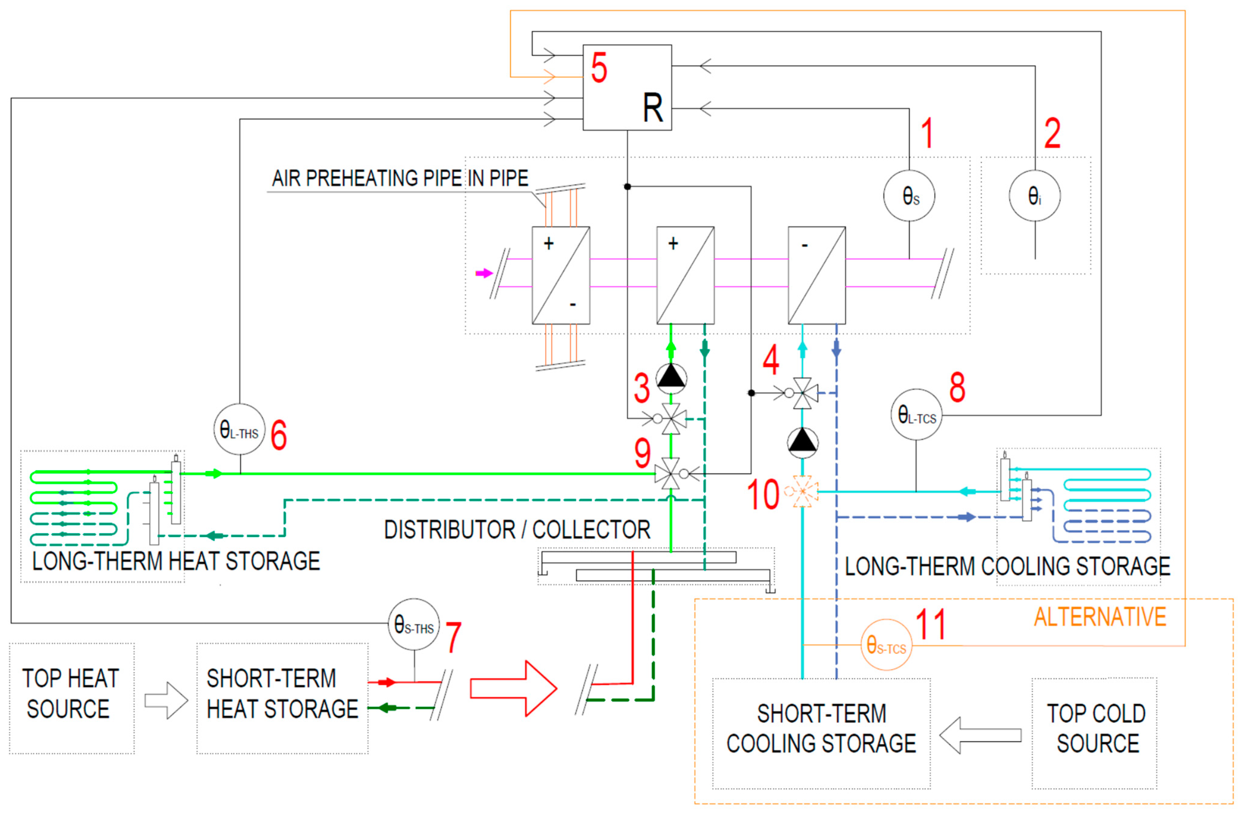
4.3.1. Control of Thermal Barrier Operation in Active Thermal Protection Mode

The principle of temperature control at the thermal barrier level in active thermal-protection mode is shown in Figure 10. The temperature of the heating or cooling water (sensor “1”), is regulated centrally in the source area, together with all circuits of the thermal barrier. The control actuator is a three-way mixing valve with actuator “3”. The controller “4” calculates the actual temperature of the supply heat-transfer medium depending on the setpoint of the thermal barrier temperature (sensor “2”) in the reference room, depending on whether it is in heating or cooling mode. For larger buildings, we recommend dividing the rooms with thermal barriers into zones according to the orientation to the cardinal directions N–S or NE–SW, where the temperature requirements of these zones for the supply temperature of the heat transfer medium may differ significantly due to the presence of heat gains from the sun.
The flow of the heat carrier into the thermal barrier circuits is controlled by the controller based on the comparison of the desired value of the heating or cooling water temperature and the temperature at the outlet of the individual heat and cold storage tanks (sensors “5”, “6”, “7”, “8”) by controlling the actuators of the respective three-way switching valves, which are schematically shown as item “9” in Figure 10, and in more detail in the schematic in Figure 9.
In the cooling operation, it is important to prevent airborne water vapor condensation on the wall structure’s surface. Therefore, each thermal barrier circuit is equipped with a contact humidity sensor (sensor “10”) installed at the coldest point of the system and a two-way actuated control valve “11”. If the humidity in the room concerned reaches a threshold value, the controller closes the cooling water supply to the circuit concerned by operating the two-way control valve with an actuator, so-called passive protection.
Figure 11 is a block diagram of the thermal barrier level temperature control system solution. The thermal barrier is built as a two-pipe system with switching between winter and summer operations. For each operation, the desired temperature value is set separately. The solar absorber, the long-term heat storage, and the short-term heat storage all supply heating water to the circuits during the heating process. The thermal barrier temperature θTB is controlled to the desired value θsp,h by changing the heating water supply temperature θs by controlling the actuator of the three-way mixing valve. The outlet temperature of the solar absorber θSA, the outlet temperature of the long-term heat storage θL-THS, and the outlet temperature of the short-term heat storage θS-THS are also sensed. If θTB = θsp,h, no control intervention is needed. If this condition is not met, the procedure is as follows:
  • If θTB < θsp,h, the inlet temperature to the thermal barrier circuit θs must be increased and at the same time the heating water supplied upstream of the three-way valve must have a higher temperature than the calculated inlet temperature θs. The controller compares the outlet temperatures θSA, θL-THS, and θS-THS in a fixed order and redirects the heating water flow from the device that satisfies the condition. If θS-THS < θs, it will commission the peak heat source. It then controls the actuation of the three-way mixing valve—opening the direct path;
  • If θTB > θsp,h, the inlet temperature to the thermal barrier circuit θs must be reduced. The controller controls the three-way mixing valve’s actuator–closes the valve’s direct path.
This procedure is repeated until the condition θTB = θsp,h is satisfied.
In the cooling operation, cooling water from long-term cold storage is fed to the thermal barrier circuits. The thermal barrier temperature θTB is controlled to the desired value θsp,c by varying the cooling water supply temperature θs by controlling the actuator of the three-way mixing valve. If θTB = θsp,c, no control intervention is required.
If this condition is not met, the procedure is as follows:
  • If θTB > θsp,c, the inlet temperature to the thermal barrier circuit θs must be reduced. Subsequently, it controls the actuator of the three-way mixing valve, thus opening the direct path. This procedure is repeated until the condition θTB = θsp,c is satisfied;
  • If θTB < θsp,c, the inlet temperature to the thermal barrier circuit θs must be increased. The controller controls the actuator of the three-way mixing valve, thus it closes the direct path of the valve.
This procedure is repeated until the condition θTB = θsp,c is satisfied.

4.3.2. Controlling the Heat-Recovery Air Handling Unit’s Operation

The principle of indoor air temperature control is shown in Figure 12. The air supplied to the heat recovery unit is preheated or cooled in a ground heat exchanger of the pipe-in-pipe type located at a non-freezing depth. The supply air temperature (sensor “1”), which is fed into the rooms after treatment, is controlled centrally for all rooms. The control actuators are the three-way control valves of the heater “3” and the cooler “4”. The controller “5” calculates the actual supply air temperature depending on the set indoor air temperature setpoint (sensor “2”) in the reference room, depending on whether it is a winter or summer operation. The controller controls the flow of the heating medium to the heater by comparing the setpoint of the supply air temperature and the temperature of the heating water at the outlet of the heat storage tanks (sensors “5”, “6”) by controlling the actuator of the three-way change-over valve “9”. The chiller is supplied with refrigerant from long-term cold storage. The temperature at the outlet of this reservoir is sensed by a sensor “8”.
Figure 13 shows a block diagram of the indoor air temperature control system. Its desired value is set separately for winter and summer operations. In heating operation, heating water is fed to the circuits from the long-term heat storage tank and the short-term heat storage tank. The indoor air temperature θi is controlled to the desired value θsp by changing the supply air temperature θs by controlling the heater’s actuator’s three-way mixing valve. The outlet temperature of the long-term heat storage tank θL-THS and the outlet temperature of the short-term heat storage tank θS-THS is also sensed. If θi = θsp, then no control intervention is required. If this condition is not met, the procedure is as follows:
  • If θi < θsp, the supply air temperature θs must be increased and at the same time the heating water supplied upstream of the three-way valve must have a higher temperature than the calculated supply air temperature θs. The controller compares the outlet temperatures θL-THS and θS-THS in a fixed order and redirects the flow of heating water from the device that satisfies the condition. If θS-THS < θs, it will commission the peak heat source. It then controls the actuation of the three-way mixing valve of the heater, thus opening the direct path;
  • If θi > θsp, the supply air temperature θs must be reduced. The controller controls the heater’s three-way mixing valve’s actuator, closing the valve’s direct path;
  • This procedure is repeated until the condition θi = θsp is met. If this condition is still not met, the unit goes into cooling operation.
In the cooling operation, cooling water from long-term cold storage is fed into the chiller. The indoor air temperature θi is controlled to the desired value θsp by changing the supply air temperature θs by controlling the actuator of the three-way radiator manifold valve. The procedure is as follows:
  • If θi > θsp, the supply air temperature θs must be reduced. The controller controls the three-way radiator diverter valve actuator, thus opening the direct path. This procedure is repeated until the condition θi = θsp is met. The heater and cooler control valves are controlled in sequence, the cooler control valve opens only after the heater control valve is fully closed and vice versa. In the future, it is recommended that a peak cooling source is designed, e.g., a heat pump, and a short-term cold store in case the desired indoor air temperature cannot be reached in cooling mode;
  • If θi < θsp, the supply air temperature θs must be increased. The controller controls the three-way radiator distribution valve’s actuator, closing the direct valve path;
  • This procedure is repeated until the condition θTB = θsp is satisfied.
For use in larger buildings, we recommend applying a drag control of the indoor air temperature according to the outdoor air temperature, which would mean a reduction in the indoor air temperature setpoint for the summer period and an increase in the indoor air temperature setpoint for the winter period. The outdoor air-temperature influence would be set separately for each plant. This would result in cooling energy savings and reduce temperature shocks as people move from the indoor to the outdoor environment and vice versa. It would also be advisable in buildings with large solar heat gains to introduce a minimum supply air temperature limit of 17 °C to avoid draughts. It is also recommended to design short-term cold storage for such buildings and a peak cooling source to cover thermal loads in cases where the temperature of the cooling water from the short-term cold store will not be sufficient to achieve thermal comfort in the cooling plant.

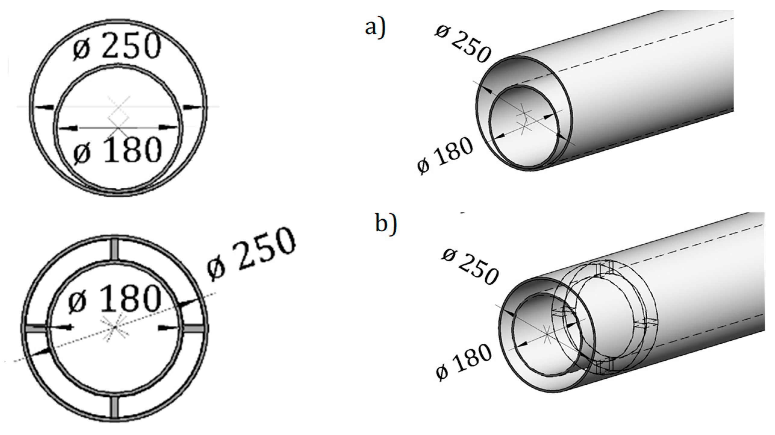
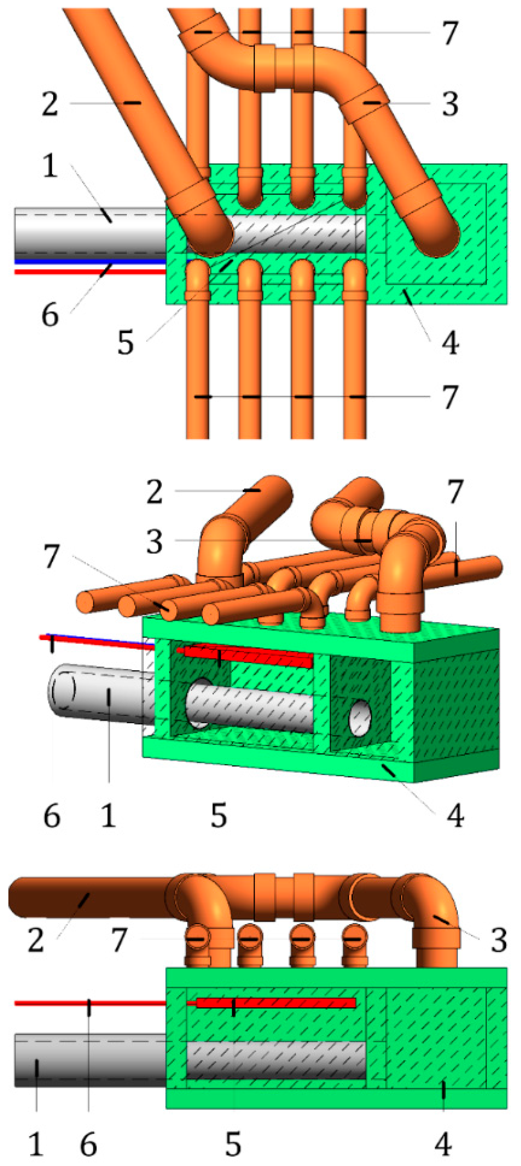
4.4. Inductive and Analogical form of Creation Innovative Method of Realization of Ventilation with Heat Recovery Pipe-in-Pipe

The pipe-in-pipe air exchanger implementation is not ideal in terms of heat exchange between the pipes and the adjacent soil as the inner pipe lies at the bottom of the outer pipe, Figure 14a. To eliminate this problem, we propose the application of spacer rings to ensure uniform airflow around the entire inner pipe (Figure 14b).
In addition, the pipe-in-pipe heat recovery air exchanger of the ISOMAX system [1] represents a risky element in the forced air ventilation system of buildings because the use of geothermic energy without a peak source of heat or cold is uncertain, unstable, and difficult to predict, which is influenced by several factors (change of external temperatures, fluctuation of groundwater level, different soil composition, etc.). For this reason, we propose the installation of a water/air heat exchanger in the air distributor and air collector chamber that will heat or cool the supply air to the building rooms as needed (Figure 15). Alternatively, this exchanger can be installed in the supply air duct.

5. Results and Discussion

The novelty of the research presented in this paper is the adaptation of the original mode of operation of the ISOMAX system to various modes for different building energy systems. Heat/cooling sources and other system components have been added that, when used in conjunction with the building control system, optimize the mode of operation and provide alternatives to buildings with fossil fuel-based heating/cooling systems that are energy safe and reliable. Partial results of our research have been published in several scientific articles and are also part of three utility models (UM SK 5749 Y1 [20], UM SK 5729 Y1 [22], UM SK 5725 Y1 [23]) and one European patent (EP 2 572 057 B1 [24]).
The new scientific results and the novelty of the research can be summarized as follows:
In Section 4.1, we analyzed the innovative operation method of combined building–energy systems of buildings;
In Section 4.2, we defined and proposed the innovative operation method and developed the wiring diagram of combined building–energy systems of buildings;
In Section 4.3, we presented the block diagram of thermal barrier temperature control in active thermal protection mode for heating and cooling, the principle of temperature control in heat/cold recovery mode, and the retrofit of the ventilation system with tube-in-tube heat recovery;
In Section 4.4, for the pipe-in-pipe heat recovery ventilation system, we proposed the installation of a water/air heat exchanger in the air distributor and air collector chamber, which will heat or cool the supply air to the rooms of the building as required. Alternatively, this heat exchanger can be installed in the supply duct of the air handling unit.

6. Conclusions

Continuous research is being executed on the RES-based integrated building energy systems. In the years between 2008 and 2013, we explored the experimental house EB2020, which we planned, coordinated the construction of, and used for experimental measures, following the completion of the prototype prefabricated house IDA I (2005–2006). We performed experimental measurements on a mobile laboratory (a simulator and optimizer for small smart devices) that we created and worked on putting into use between 2015 and 2021. The objectives of our further research are:
  • To develop further equivalent variant technical solutions of combined building–energy systems using RES versus fossil fuel-based heat/cooling sources meeting the energy security and self-sufficiency of buildings in Slovakia and Europe;
  • To develop a methodology for calculating, selecting, and assessing combined building–energy systems using RES;
  • To apply the proposed methodology for the calculation, selection, and assessment for selected combined building–energy systems using RES in buildings;
  • To develop a methodology for the application of combined building–energy systems using RES in buildings in the BIM (Building Information Modeling) model;
  • Ensuring the automated transfer of the proposed database of combined building–energy systems using RES into the BIM model);
  • Creating a unified framework to interconnect the different systems, including software solutions;
  • Verification of the proposed solution on a concrete construction project developed in the BIM model.

Author Contributions

Conceptualization, D.K. (Daniel Kalús), D.K. (Daniela Koudelková), M.K., V.M. and M.S.; methodology, D.K. (Daniel Kalús), D.K. (Daniela Koudelková) and M.K.; validation, D.K. (Daniel Kalús), D.K. (Daniela Koudelková) and M.K.; formal analysis, D.K. (Daniel Kalús); investigation, D.K. (Daniel Kalús), D.K. (Daniela Koudelková) and M.K.; resources, D.K. (Daniel Kalús), D.K. (Daniela Koudelková), M.K. and V.M.; data curation, D.K. (Daniel Kalús), D.K. (Daniela Koudelková), M.K., V.M. and M.S.; writing—original draft preparation, D.K. (Daniel Kalús), D.K. (Daniela Koudelková), M.K., V.M. and M.S.; writing—review and editing, D.K. (Daniel Kalús), D.K. (Daniela Koudelková), M.K., V.M. and M.S. All authors have read and agreed to the published version of the manuscript.

Funding

The publication of this work was financially supported by EHBconsulting s. r. o. At the same time, we express our sincere thanks to the private investor Ing. Tomáš Ircha, who significantly supported the research in the field of combined building and energy systems.

Institutional Review Board Statement

Not applicable.

Informed Consent Statement

Not applicable.

Data Availability Statement

The data that support the findings of this study are available from the corresponding author upon reasonable request.

Acknowledgments

This research was supported by the Ministry of Education, Science, Research and Sport of the Slovak Republic grant VEGA 1/0304/21. This research was supported by the Ministry of Education, Science, Research and Sport of the Slovak republic grant KEGA 005STU-4/2021.

Conflicts of Interest

The authors declare no potential conflict of interest concerning the research, authorship, and/or publication of this Article.

References

  1. Krecké, E.D. PATENT SK 284 751: Energetické Zariadenie Budov. [Energy Equipment of Buildings]. Patent In Vestník ÚPV SR č. 11/2005, 3 November 2005. [Google Scholar]
  2. ISOMAX—Terrasol Building Technologies. Air Conditioning of Buildings by Near-Surface Geothermal Energy; Krecké, E.D., Kunkel, K., Eds.; Issued by Verein Deutscher Ingenieure; Structural Engineering Yearbook: Dűsseldorf, Germany, 2005; Available online: http://www.isomax-terrasol.eu (accessed on 10 August 2022).
  3. Ulbrich, R.; Milaszewicz, M.; Rachel, M. Possibility of application of renewable energy sources in buildings. Proc. ECOpole 2007, 1, 65–71. [Google Scholar]
  4. Guinea, D. Towards Zero-Energy Consumption Buildings: Dynamic control of building shell energy flow. In Proceedings of the 2nd National Congress on Thermal and Acoustic Isolation, Madrid, Spain, 16–17 October 2008. [Google Scholar]
  5. Rijksen, D.O.; Wisse, C.J.; van Schijndel, A.W.M. Reducing peak requirements for cooling by using thermally activated building systems. Energy Build. 2010, 42, 298–304. [Google Scholar]
  6. Krzaczek, M.; Kowalczuk, Z. Thermal Barrier as a technique of indirect heating and cooling for residential buildings. Energy Build. 2011, 43, 823–837. [Google Scholar] [CrossRef]
  7. Arteconi, A.; Costola, D.; Hoes, P.; Hensen, J.L.M. Analysis of control strategies for thermally activated building systems under demand side management mechanisms. Energy Build. 2014, 80, 384–393. [Google Scholar] [CrossRef] [Green Version]
  8. Jae-Han, L.; Jin-Hee, S.; Seung-Yeong, S. Development of operational guidelines for thermally activated building system according to heating and cooling load characteristics. Appl. Energy 2014, 126, 123–135. [Google Scholar]
  9. Park, S.H.; Chung, W.J.; Yeo, M.S.; Kim, K.W. Evaluation of the thermal performance of a Thermally Activated Building System (TABS) according to the thermal load in a residential building. Energy Build. 2014, 73, 69–82. [Google Scholar] [CrossRef]
  10. Liu, Z.B.; Zhang, L.; Gong, G.C.; Luo, Y.; Meng, F. Evaluation of a prototype active solar thermoelectric radiant wall system in winter conditions. Appl. Therm. Eng. 2015, 89, 36–43. [Google Scholar] [CrossRef]
  11. Dai, L.H.; Shang, Y.; Li, X.L.; Li, S.F. Analysis on the transient heat transfer process inside and outside the borehole for a vertical U-tube ground heat exchanger under short-term heat storage. Renew. Energy 2016, 87, 1121–1129. [Google Scholar] [CrossRef]
  12. Shen, C.; Li, X. Energy saving potential of pipe-embedded building envelope utilizing low-temperature hot water in the heating season. Energy Build. 2017, 138, 318–331. [Google Scholar] [CrossRef]
  13. Chung, W.J.; Lim, J.-H. Cooling operation guidelines of thermally activated building system considering the condensation risk in hot and humid climate. Energy Build. 2019, 193, 226–239. [Google Scholar] [CrossRef]
  14. Chen, S.; Yang, Y.; Olomi, C.; Zhu, L. Numerical study on the winter thermal performance and energy saving potential of thermo-activated PCM composite wall in existing buildings. Build. Simul. 2020, 13, 237–256. [Google Scholar] [CrossRef]
  15. Kalús, D.; Straková, Z.; Kubica, M. Parametric Study of Heating and Cooling Capacity of Interior Thermally Active Panels. Period. Polytech. Mech. Eng. 2021, 65, 269–279. [Google Scholar] [CrossRef]
  16. Kalús, D.; Cvíčela, M.; Janík, P.; Kubica, M. Combined Building-Energy Systems with Heat Transfer Control by Building Constructions using RES. In IOP Conference Series: Materials Science and Engineering 2021 Nov 1; IOP Publishing: Bristol, UK, 2021; Volume 1203, p. 032091. [Google Scholar]
  17. Kalús, D.; Mučková, V.; Koudelková, D. Energy, Economic and Environmental Assessment of Thermal Barrier Application in Building Envelope Structures. Coatings 2021, 11, 1538. [Google Scholar] [CrossRef]
  18. Kalús, D.; Janík, P.; Kubica, M. Experimental house EB2020–Research and experimental measurements of an energy roof. Energy Build. 2021, 248, 111172. [Google Scholar] [CrossRef]
  19. Kalús, D.; Janík, P.; Koudelková, D.; Mučková, V.; Sokol, M. Contribution to research on ground heat storages as part of building energy systems using RES. Energy Build. 2022, 267, 112125. [Google Scholar] [CrossRef]
  20. Kalús, D. UTILITY MODEL SK 5749 Y1 (UTILITY MODEL): Spôsob Prevádzky Kombinovaného Stavebno-Energetického Systému Budov a Zariadenie. [Method of Operation of a Combined Construction-Energy System of Buildings and Equipment]. Vestník ÚPV SR No.: 5/2011, 1 April 2011. [Google Scholar]
  21. Kalús, D. The Contract for Work HZ 04–309–05–Design of a Passive House Using Solar and Geothermic Energy. K–TZB SvF STU Bratislava, 1 September 2006. [Google Scholar]
  22. Kalús, D. UTILITY MODEL SK 5729 Y1 (UTILITY MODEL): Samonosný Tepelnoizolačný Panel pre Systémy s Aktívnym Riadením Prechodu Tepla. [Self-Supporting Thermal Insulation Panel for Systems with Active Heat Transfer Control]. Vestník ÚPV SR No.: 4/2011, 28 February 2011. [Google Scholar]
  23. Kalús, D. UTILITY MODEL SK 5725 Y1 (UTILITY MODEL): Tepelnoizolačný Panel pre Systémy s Aktívnym Riadením Prechodu Tepla. [Thermal Insulation Panel for Systems with Active Heat Transfer Control]. Vestník ÚPV SR No.: 4/2011, 25 February 2011. [Google Scholar]
  24. Kalús, D. European Patent EP 2 572 057 B1: Heat Insulating Panel with Active Regulation of Heat Transition. Bulletin 2014/42 European Patent Office, International Application Number: PCT/SK2011/000004, International Publication Number WO 2011/146025 (24.11.2011 Gazette 2011/47), 15 October 2014. [Google Scholar]
Figure 1. Scheme of ISOMAX system operation. 1—energy (solar) roof; 2—exhaust air from the interior; 3—reheating of hot water in an electric or gas hot water tank; 4—heat barrier in the outer walls; 5—drinking water supply to the building; 6—control unit; 7—supply ventilation air to the interior; 8—peripheral zone-ground heat storage; 9—ground heat storage (GHS); 10—cooling circuits; 11—central GHS; 12—combined distributor and collector of ventilation air; 13—thermal insulation GHS; 14—geothermal energy; 15—solar energy; 16—internal heat sources; 17—passive use of solar energy; 18—shelter for air conditioning equipment; 19—ventilation air extraction from the building; 20—fresh air intake for ventilation; 21—heat recovery–duct in the duct–recuperative ventilation [1,2].
Applsci 12 10214 g001
Figure 2. Passive cooling using registers of pipes located in the ground near the building underground at a depth of 1 to 2 m [1,2].
Applsci 12 10214 g002
Figure 3. A thermal barrier integrated into the building construction separates the load-bearing, static portion of the perimeter wall and the thermal insulation portion [1,2].
Applsci 12 10214 g003
Figure 4. Thermal barrier embedded in the load-bearing part of reinforced concrete panels bounded on the interior and exterior side by thermal insulation [1,2].
Applsci 12 10214 g004
Figure 5. Schematic representation of thermal barrier walls [1,2]. (A)—Reinforced concrete wall insulated on both sides; (B)—Masonry wall; (C)—Timber house wall.
Applsci 12 10214 g005
Figure 6. Heat recovery ventilation pipe in a pipe located both below the building and outside the building [1,2].
Applsci 12 10214 g006
Figure 7. ISOMAX system control [1,2].
Applsci 12 10214 g007
Figure 8. Diagram of the combined building and energy system’s functional wiring. 1—solar absorber (energy roof, solar collector, etc.); 2—short-term heat storage; 3—long-term heat storage; 4—active thermal protection circuits (building structure with an internal heat source); 5—mixing and control equipment; 6—low-temperature heating circuits; 7—heat recovery ventilation equipment; 8—cooling circuits located in the ground outside the building; 9—peak cooling source; 10—short-term cold storage; 11—high-temperature cooling circuits; 12—waste heat from the drainage system; 13—waste heat from the technological process; 14—electricity generation equipment (photovoltaics, wind power plant, etc.); 15—building control system; 16—batteries for storing the generated electricity, and others, 17—top heat source [20].
Applsci 12 10214 g008
Figure 9. Simplified wiring diagram of the innovative technical solution for energy systems [21]. 1b—solar roof; 2—short-term heat storage; 3a—long-term heat storage; 3b—water preheating; 4—active thermal protection circuits (building structure with an internal heat source); 5—mixing and control equipment; 6—low-temperature heating circuits; 7—heat recovery ventilation equipment; 8—cooling circuits located in the ground outside the building; 11—high-temperature cooling circuits; 12—waste heat from the drainage system; 15—building control system; 17a—fireplace (top heat source), 17b—boiler (top heat source).
Applsci 12 10214 g009
Figure 10. The fundamentals of temperature regulation at the thermal barrier level while using active thermal protection. 1—heating water supply temperature sensor; 2—thermal barrier temperature sensor; 3—three-way mixing valve with actuator; 4—controller; 5—output solar absorber temperature sensor; 6—heating water temperature sensor at the long-term heat storage tank output; 7—cooling water temperature sensor at the long-term heat storage tank output; 8—heating water temperature sensor at the short-term heat storage tank output; 9—three-way diverter valve with actuator; 10—contact dew point sensor; 11—two-way control valve with actuator.
Applsci 12 10214 g010
Figure 11. Block diagram of thermal barrier temperature control for active thermal protection function mode. θTB—thermal barrier temperature; θsp,h—thermal barrier temperature setpoint—heating mode; θsp,c—thermal barrier temperature setpoint—cooling mode; θSA—output solar absorber temperature; θL-THS—output long-term heat store temperature; θS-THS—output short-term heat store temperature; θS-TCS—output short-term cold store temperature; θL-TCS—output long-term cold store temperature; θs—heating/cooling water supply temperature behind the three-way mixing valve before the controller; θs’—heating/cooling water supply temperature behind the three-way mixing valve after the controller.
Applsci 12 10214 g011
Figure 12. Block diagram of indoor air temperature control during the recuperative air handling unit operation. 1—supply air temperature sensor; 2—indoor air temperature sensor; 3—heater three-way heater mixing valve with actuator; 4—three-way distribution cooler valve with actuator; 5—controller; 6—heating water temperature sensor at the long-term heat storage tank output; 7—heating water temperature sensor at the short-term heat storage tank output; 8—cooling water temperature sensor at the long-term heat storage tank output; 9—three-way diverter valve with actuator for the heater; 10—three-way diverter valve with actuator for cooler; 11—cooling water temperature sensor at the short-term heat storage tank output.
Applsci 12 10214 g012
Figure 13. The indoor air temperature control principle during the operation of the recuperative air handling unit. θi—indoor air temperature; θsp—indoor air ttemperature setpoint; θL-THS—output long-term heat store temperature; θS-THS—output short-term heat store temperature; θL-TC—output long-term cold store temperature; θs—supply air temperature before regulator intervention; θ—supply air temperature behind the controller intervention.
Applsci 12 10214 g013
Figure 14. A look at a real installation of a pipe-in-pipe heat recovery air exchanger and the innovative solution with spacer rings [2,20]. (a) pipe in a pipe without the use of spacer rings, (b) pipe in a pipe with the use of spacer rings.
Applsci 12 10214 g014
Figure 15. Chamber of pooled air distributor and air collector for ventilation with heat recovery with installed water/air exchanger. 1—heat recovery heat exchanger pipe-in-pipe; 2—supply of treated air to the building; 3—air exhaust from the building; 4—chamber of the distributor and collector of ventilation air; 5—liquid heat exchanger of water-air type; 6—the heat transfer medium’s supply and return; 7—supply pipes of treated air on the first floor.
Applsci 12 10214 g015
Publisher’s Note: MDPI stays neutral with regard to jurisdictional claims in published maps and institutional affiliations.

