Article

Influence of Ion Implantation on the Wear and Lifetime of Circular Saw Blades in Industrial Production of Wooden Door Frames

1
Department of Mechanical Processing of Wood, Institute of Wood Sciences and Furniture, Warsaw University of Life Sciences, 159 Nowoursynowska St., 02-776 Warsaw, Poland
2
Plasma/Ion Beam Technology Division, Material Physics Department, National Centre for Nuclear Research Świerk, 7 Sołtana St., 05-400 Otwock, Poland
3
Porta KMI Poland, 54 Szkolna St., 84-239 Bolszewo, Poland
4
Department of Furniture Design, Faculty of Forestry and Wood Technology, Poznań University of Life Sciences, 28/32 Wojska Polskiego St., 60-627 Poznań, Poland
5
Center of Wood Technology, Łukasiewicz Research Network, Poznań Institute of Technology, Winiarska St. 1, 60-654 Poznań, Poland
6
General Engineering Solutions, 96/98 Zwycięstwa Avenue, 81-451 Gdynia, Poland
*
Author to whom correspondence should be addressed.
Appl. Sci. 2022, 12(20), 10211; https://doi.org/10.3390/app122010211
Submission received: 19 September 2022 / Revised: 6 October 2022 / Accepted: 9 October 2022 / Published: 11 October 2022
(This article belongs to the Special Issue Application of Wood Composites III)

Abstract

:
The paper presents the effect of nitrogen ion implantation on tool wear and tool life during the sawing of wood-based materials in the industrial production of door frames. The circular saw blades used in machining had WC-Co carbide teeth. Saw teeth were modified by ion implantation. The total implanted dose of nitrogen ions was 5 × 1017 cm−2 (2 × 2.5 × 1017 cm−2) and ions were implanted at 50 kV acceleration voltage. Tool wear testing was carried out under industrial production conditions for the door frames made of wood-based materials. The wear of circular saw teeth was evaluated under an optical microscope. Based on the tool’s wear and machining distance, a mathematical linear model of the non-treated and ion-implanted tools’ life was developed using the linear least squares method. The study showed less wear of the implanted circular saw blades and a significant increase in the estimated lifetime of modified tools compared to non-treated (control) tools. At the same time, activation of the surface of the implanted circular saw teeth was observed, manifested by an increase in adhesion and the appearance of the secondary structures on the WC-Co surface.

1. Introduction

The wear and lifetime of cutting tools is an important technological and cost problem in various industries, including the broadly understood wood industry, in the production of furniture and construction joinery. Tool wear is a continuous process that begins with the first operation performed by the new tool, lasting throughout the tool’s life, and ends when the tool is considered dull, i.e., not suitable for further work, after reaching the blunting criterion. The blunting criterion can be based on a direct tool wear indicator, measured using an optical microscope, and reaching its specific limit value is the moment when the tool ends (end of tool’s life) and when it is replaced with a new tool [1].
The direct wear indicator is most often used in scientific research because it provides reliable information about the condition of the tool. Unfortunately, in industrial production conditions, the measurement of the direct wear indicator is difficult, and often even impossible; therefore, in such conditions, indirect indicators of tool wear related to the quality of machining are used. The criterion of blunting becomes, for example, insufficient edge quality or low dimensional accuracy, or the condition of the surface with too high roughness. It is the machining quality associated with the workpiece that determines the moment when the tool is dull and its replacement with a new tool. The problem with the blunting criterion adopted in this way is the non-obvious nature of the relationship between tool wear and the quality of machining. The obtained correlations between direct wear indicators and machining quality indicators are often at an average level, thus also showing the influence of factors other than tool wear [2]. Therefore, when determining the tool’s life on the basis of qualitative indicators, this aspect should be taken into account.
Most commonly, in the machining of widely understood wood materials, tools with WC-Co sintered tungsten carbide blades are used, which are an economically viable alternative to more expensive polycrystalline diamond tools, as well as to non-durable steel tools [3,4]. The tool’s life with polycrystalline diamond blades is higher than that of other tool materials; however, certain functional features made it so that tungsten carbide began to dominate in the machining of wood-based materials. It was tungsten carbide that showed lower wear from brittle fracture when sawing a three-layer particleboard at high speeds. This wood-based construction material is considered to be extremely difficult to machine due to the significant content of mineral substances (in the form of sand). Polycrystalline diamond, as an extremely hard tool material and therefore resistant to friction, is characterized by insufficient resistance to brittle fracture, especially under high speed conditions, which occurs during cutting with circular saws [5,6,7].
The indicated technological advantage in this one aspect of machining with the use of WC-Co tungsten carbide is an impulse for its widespread use in the machining of wood materials. However, there is still a significant difference in the tribological durability (resistance to friction) between WC-Co and a polycrystalline diamond. Therefore, attempts have been made to improve the abrasion resistance when cutting wood materials by modifying the surface layer of WC-Co tools in the ion implantation process, nitriding and the use of anti-abrasive coatings [1,8,9,10,11].
Ion implantation is a non-equilibrium method [12,13,14,15] of material doping in which the ionized atoms are accelerated in the electric field to speeds from hundreds to thousands of kilometres per second, formed into a beam and implanted into the surface of the modified material. Moreover, modified materials are free from the delamination of a layer characteristic for the modification of the surface with anti-abrasive coatings [4]. Ion implantation can be used for the modification of the properties of the different materials, such as, for example, metals and their alloys [16], ceramics [17], glasses [18], polymers [19] or composites [20].
The increase in tool life after ion implantation is associated with many complex phenomena occurring on the surface of the tool during cutting and is the surface’s response to wear mechanisms occurring during friction [21].
The aim of industrial research was to evaluate the effect of the nitrogen ion implantation of circular saw blades with WC-Co teeth on the wear and tool life during CNC sawing of door frames in industrial production conditions. These researches deal only with the technological aspect and not with the economical one.

2. Materials and Methods

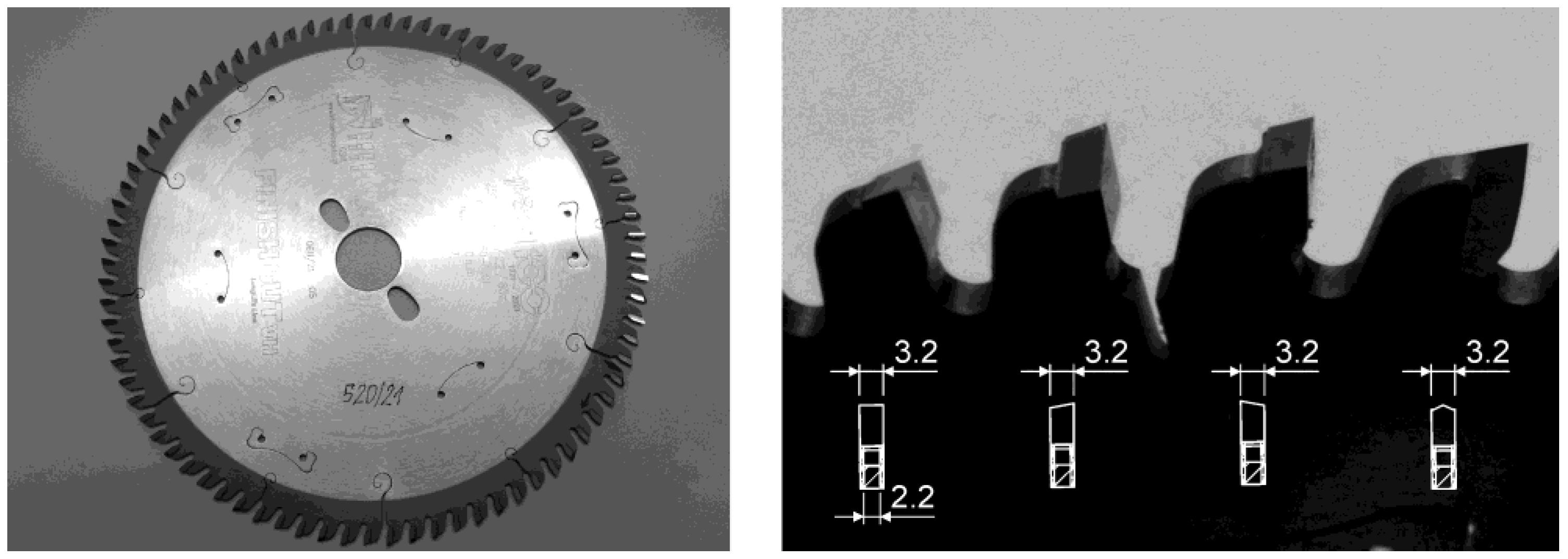
2.1. WC-Co Saw Blades

The commercially available circular saw blades of the Globus brand and HM Finish Cut VH LongLife Line series, symbol PS362-0250-0001 (Figure 1 left), with the special teeth geometry GSML (group toothing, flat top teeth, alternate top bevel teeth and top bevel teeth—Figure 1 right), dedicated to hard dry wood cutting, along with exotic and fruitwood and for wood-derived materials, especially for ripping of high-density boards covered with natural veneers, produced by Fabryka Pił i Narzędzi “WAPIENICA” (Bielsko-Biała, Poland), were used for the investigations. The teeth of the circular saw are made of WC-Co cemented carbide with a grain size below 0.2 µm (nanograin sintered carbide according to the manufacturer’s declaration and based on the classification presented by Wilkowski et al. 2021) with a hardness of 2250 HV30 (according to the manufacturer’s data). The circular saw blades have the following geometry: clearance angle α = 15°, wedge angle β = 70°, rake angle γ = 5° and cutting angle σ = 85°.
The used circular saw blades characterized the following main technical parameters: diameter of 250 mm, teeth number of 80, blade thickness of 2.2 mm, teeth width of 3.2 mm and maximum rotational speed of 7500 rpm.

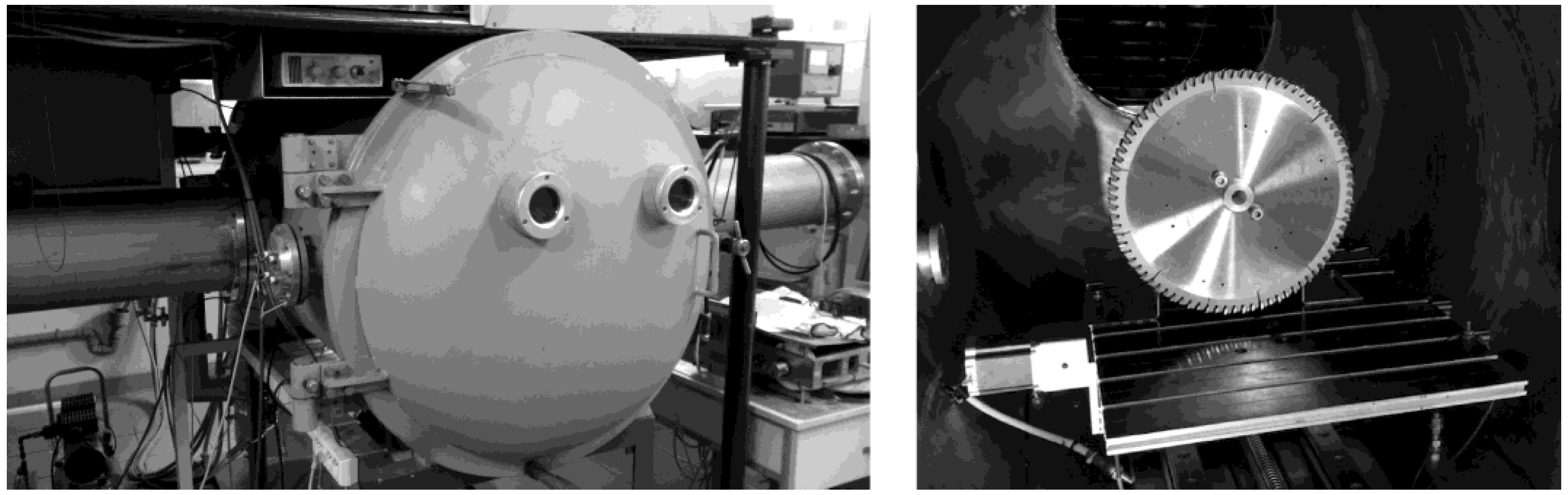
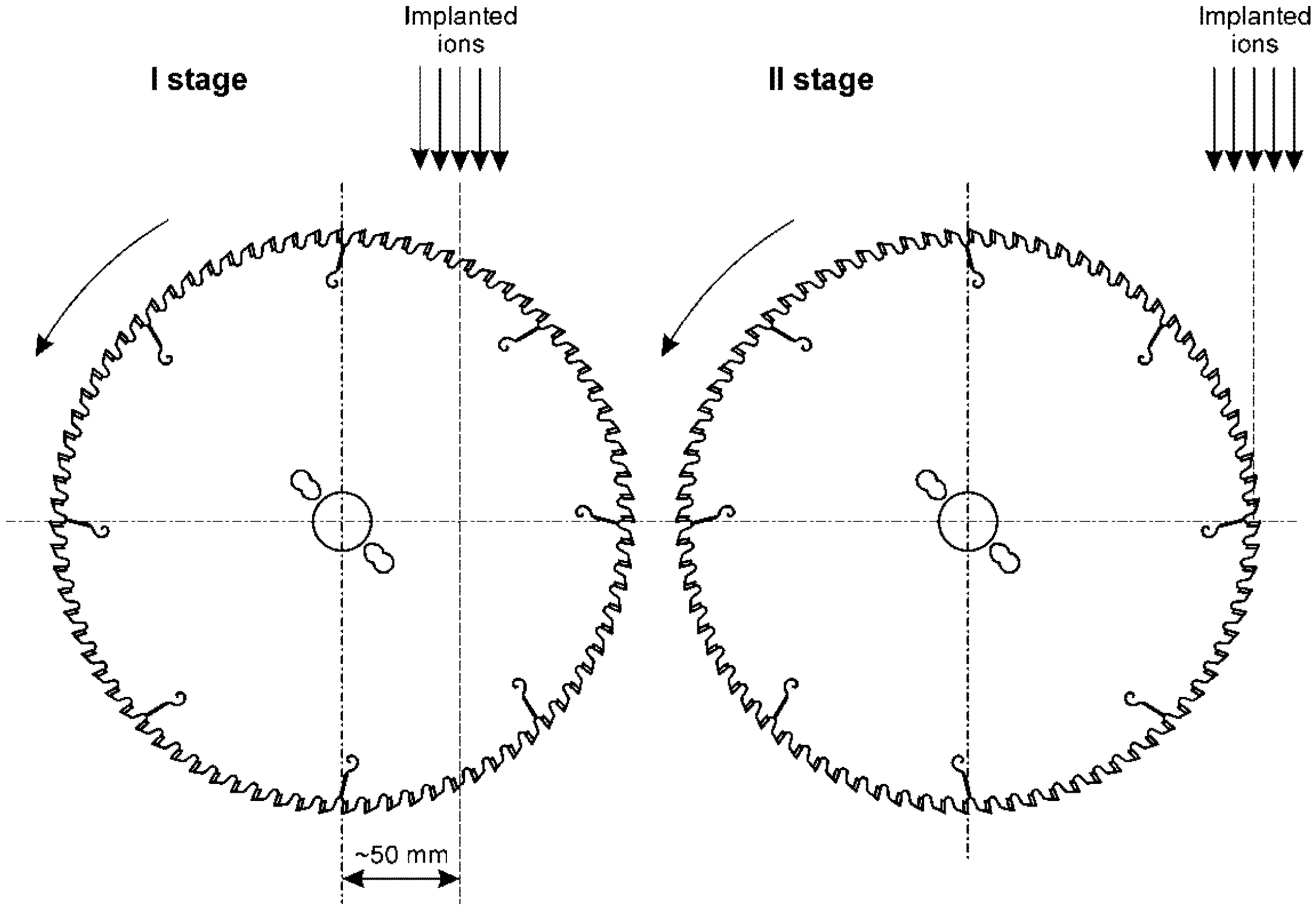
2.2. Nitrogen Ion Implantation

The circular saw blades described above were implanted using the semi-industrial gaseous ion implanter, with a non-mass-separated ion beam, exploited in National Centre for Nuclear Research Świerk (Otwock, Poland), described in detail elsewhere [22]. Before the processing, the saw blades were washed in high purity acetone. Next, three saw blades described above were put together in a package and placed in the implanter chamber (Figure 2).
Nitrogen of 5N purity was used as the source of the implanted ions. The total implanted dose of nitrogen ions was 5 × 1017 cm−2 (2 × 2.5 × 1017 cm−2) and ions were implanted at 50 kV acceleration voltage. The current of the continuous ion beam was about 300 µA, which gives the ion current densities from about 15 µA/cm2 for the assumed value of the implantation area of 20 cm2 (ion beam diameter is about 50 mm, without a significant decrease in current density). The maximum estimated temperature value of the implanted tools did not exceed 200 °C. The time of the ion implantation was 11 h 40 min. (700 min) per stage. Such values of the main parameters of the implantation correlate with previous investigations, e.g., [1,4].
The ion implantation was provided in two stages. The details of these are presented in Figure 3. In the first stage, the ion beam axis was moved about 50 mm with respect to the axis of the saw blades. In the second stage, the ion beam axis was moved to near the tangent of the saw blades. In both cases, the saw blades rotated with the rotation speed of 0.3 s−1, i.e., 18 rpm.
The ion implantation processes were supported by Monte Carlo simulations of the main parameters of the depth profiles of the implanted elements (such as peak volume dopant concentration Nmax, projected range Rp, range straggling ΔRp, kurtosis and skewness) [23], using freeware-type code SRIM-2013.00—The Stopping and Range of Ions in Matter [24]. The simulation was performed for 100,000 implanted ions of nitrogen to three kinds of the implanted surface, i.e., W-C-Co material (substitute of WC-Co), and for the comparison, to two main components of WC-Co carbide, i.e., W-C (substitute of WC) material and Co. W-C-Co and W-C materials were used because the modelling codes treat the sample as a set of atoms that do not form chemical compounds.
The tool manufacturer does not provide the exact original composition of the cemented carbide used. Therefore, the material parameters of the popular in industry KCR08 carbide have been applied to the modelling. The composition of the W-C-Co material was: 90.86% of tungsten, 5.94% of carbon and 3.2% of cobalt in weight percentages, i.e., 47.4% of tungsten, 47.4% of carbon and 5.2% of cobalt in atomic percentages. Its density adopted for the simulation was 15.2 g/cm3. WC density of 15.63 g/cm3 and Co density of 8.9 g/cm3 were adopted in the other cases.
The implanted nitrogen was delivered as two kinds of ions, i.e., N2+ + N+, in the ratio ~1:1, so there were two elementary charges per three atoms. For example, in the case of the N2 molecule implanted with the acceleration voltage of 50 kV (see Table 1), each atom carries the energy of 25 keV, according to the law of energy conservation. It means that, for example, for a total fluence of 2.5 × 1017 cm−2, the fluence of 0.83 × 1017 cm−2 is implanted with the energy of 50 keV and the fluence of 1.67 × 1017 cm−2 is implanted with the energy of 25 keV. The Average Charge State (ACS), a more popular parameter for the calculation/modelling, which is an equivalent of the sum of profiles for the individual ion kinds, was at the level of 0.67 [23].
The angle of the ion incidence was defined as 0° (perpendicular to the implanted target). The simulations were performed for room temperature implantation. The modelling did not take into account the phenomenon of substrate sputtering by the implanted ions. The theoretical values of the sputtering yield Y were additionally calculated, using the commonly known freeware-type quick ion implantation calculator SUSPRE [25], from the energy deposited in the surface region of the material using the Sigmund formula.

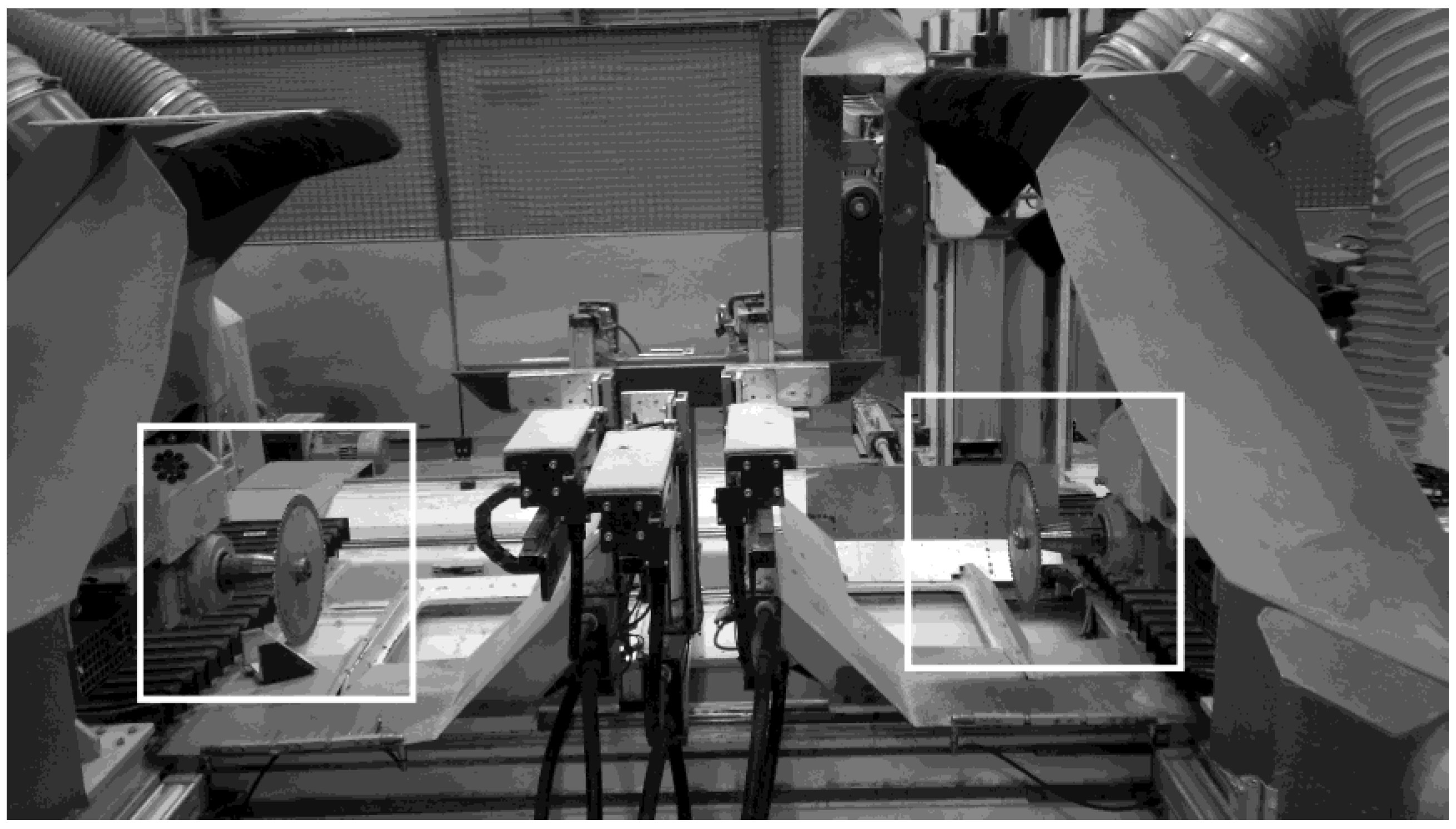
2.3. Industrial Tool Life Tests
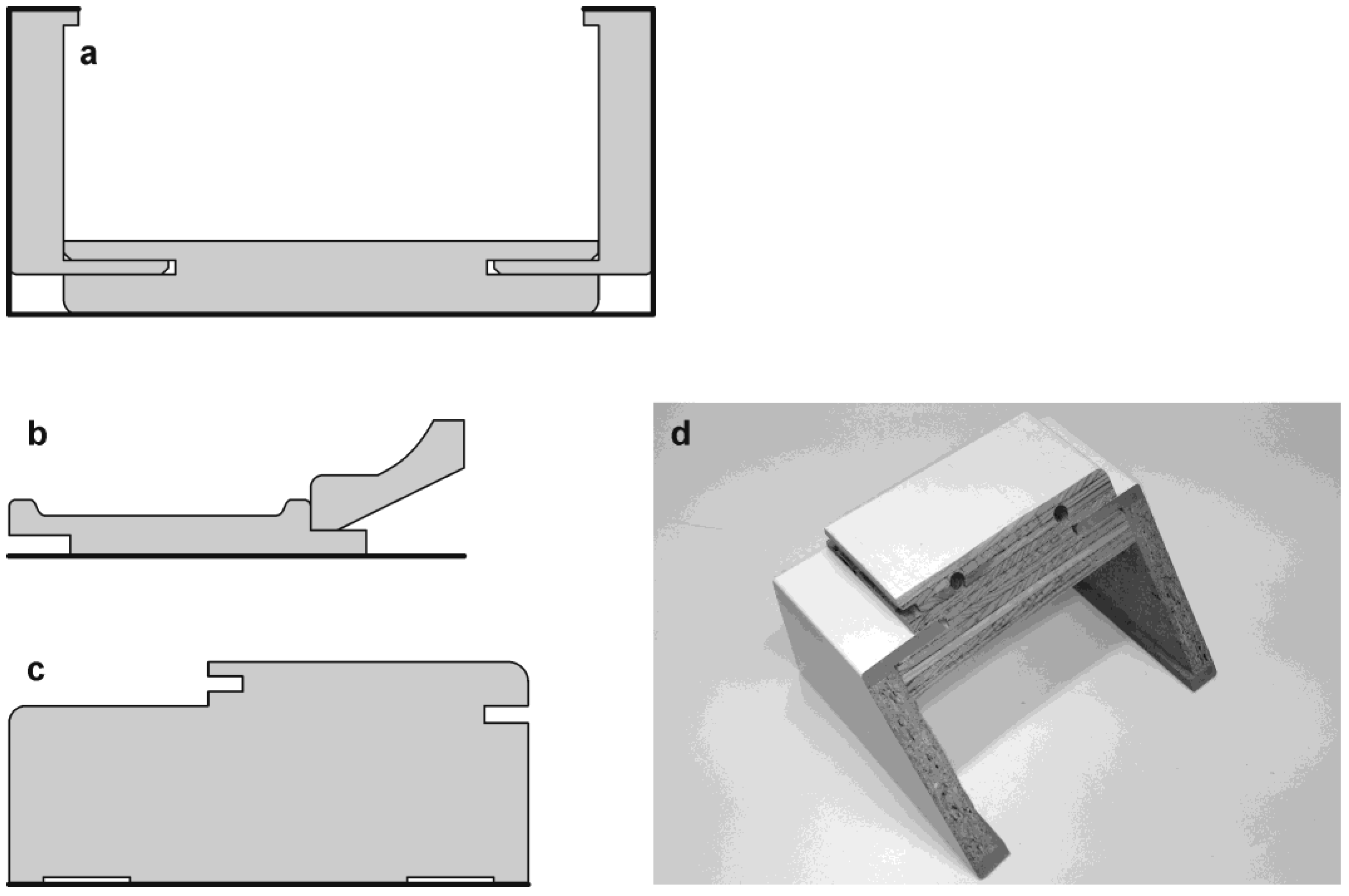
In the next step, the circular saw blades were tested in industrial conditions in Porta KMI Poland factory (Ełk, Poland) for wear and tool life during formatting door frames. The tool life tests of circular saws were carried out with the use of two of the same CNC machine tools for formatting elements of wooden door frames. These were double-aggregate Euro TF Robot Center machines (Marzani Progetti S.R.L., Sant’Angelo Lomellina, Italy). A circular saw was attached to each of the machine aggregates, therefore two tools (set) worked simultaneously on one machine—non-treated (control) and ion-implanted circular saw blade. The tools simultaneously cut the same element of the door frame on both sides, therefore, in total, they performed the same cutting length (Figure 4).
During the machining, constant cutting parameters (the feed speed of 5 m/min, the spindle speed of 7500 rpm and the feed per tooth of 0.008 mm) were maintained. These were the standard cutting parameters used when sawing on this machine tool in the current operation of an industrial factory.
At the same time, during machining, the quality edge of wooden door frames was visually monitored by the operator and when the edge quality decreased below the level specified in the factory standard, it was decided to stop cutting and replace two circular saw blades working on the same machine tool. In tool life tests, three non-treated (control) and three ion-implanted circular saw blades were used.

2.4. Workpiece

The different door frame components were machined during the tool life industrial tests. The door frames were made of various wood-based materials (chipboard, medium-density fibreboard MDF, high-density fibreboard HDF, plywood and glued softwood, knotless, high-quality). The schemes of the cross-section frame’s components are presented in Figure 5a–c and, additionally, an example of a door frame obliquely sawed (Figure 5d). The total cutting length of tool (total feed length) was calculated based on the unit length of cutting of a frame type and the number of frames machined by particular pair of circular saw blades.

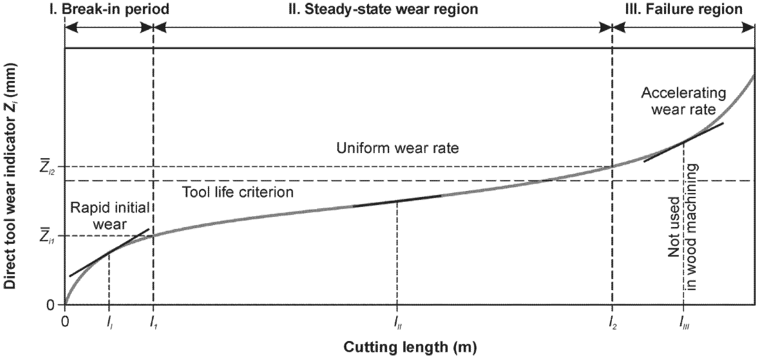
2.5. Tool Wear Measurement and Tool Life Estimation

The measurement of circular saw blades’ wear was carried out after industrial tool life tests, using a workshop (optical) microscope Mitutoyo TM-510 (Mitutoyo Corporation, Kawasaki, Japan). The oblique teeth of circular saws were selected for the wear tests, because of the set of four geometries (straight tooth, oblique to the left, oblique to the right and trapezoidal tooth), the oblique teeth were worn the most. From a metrological point of view, what is greater should be measured, because it is easier and with a smaller relative error to assess the wear. There were 40 oblique teeth on each of the circular saws. Figure 6 shows what direct tool wear indicator was measured. Retraction of the cutting edge was measured on the bisector of blade angle (Figure 6). The teeth of new (non-cutting) circular saws were used to determine the base value of the direct wear indicator. The value of actual wear was calculated as follows
Z i = W z i W ¯ z 0   mm
where:
  • Z i —actual wear of a given tooth in (mm),
  • W z i —measured wear of a given tooth in (mm),
  • W ¯ z 0 —average value of the measured base indicator of new saw teeth in (mm).
The wear of one circular saw blade was obtained by averaging 40 values of actual wear of teeth for that saw ( Z i ¯ indicator). Such calculations were made for all six tools.
The average wear of circular saw teeth is not this tool’s life. In order to determine the tool’s life, it is necessary to estimate the total cutting length (total feed length) until the value of blunting criterion (tool life criterion), that is the value of the direct wear indicator, from which tool is blunted and not suitable for further machining.
In continuous operation of the industrial plant and during the experiment, circular saw blades were replaced based on the assessment of the quality of machining edges by an operator of the machine tool. In tool life tests it is such an unreliable indicator (it depends not only on tool wear, but also on the condition of the machine tool, operator’s subjective assessment, material quality, etc.) that it was necessary to calculate the tool’s life based on measured tool wear and total cutting length performed.
Tool life was therefore determined using the point estimation and linear least squares method as the most widely used analytical method of straight line fitting. Name of the method results from the fact that we are looking for a line with such parameters that the sum of the squared differences of experimental values y i calculated from the equation of the line a x i + b is as small as possible (Equation (2)).
M a , b = i = 1 n [ y i a x i + b ] 2 = min
The differences r i = y i a x i + b are called residuals. The essence of the linear least squares method is to minimize the sum of squares of residuals.
The adopted linear model is true for the second wear phase (steady-state wear region) on the classic wear curve (Lorenz wear curve—Figure 7). To determine the linear wear functions of non-treated and ion-implanted circular saw blades, the measured values of direct wear indicators and the total cutting length in industrial tool life tests were used. In calculations of tool life, the limit value of the direct wear indicator was assumed to be 0.5 mm as the blunting criterion (tool life criterion). Thus, the measure of tool life was the estimated total cutting length up to 0.5 mm criterion. Moreover, the relative index of tool life was calculated for the ion-implanted tools in relation to the untreated tools according to the following equation
R I = L I I / L N T
where:
  • R I —relative index of tool life,
  • L I I —estimated total cutting length of ion-implanted tools in (m),
  • L N T —estimated total cutting length of non-treated tools in (m).

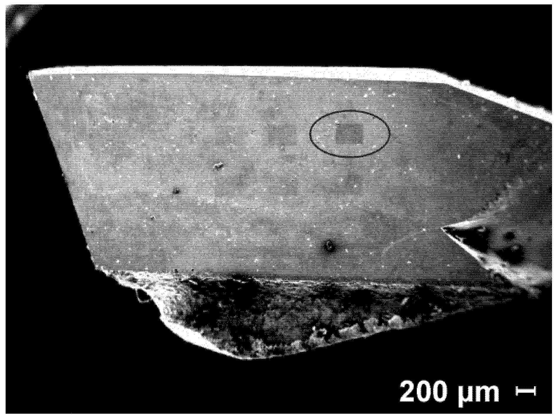
2.6. EDS Tests of the Tooth Surface after Machining

After tool life tests, the surface of the teeth of circular saw blades was examined with the use of Zeiss EVO® MA10 scanning electron microscopy (SEM) (Carl Zeiss, Oberkochen, Germany) with EDX Bruker XFlash Detector 5010 energy dispersive spectroscopy system (EDS) + dedicated Quantax 200, Esprit 1.9 code (Bruker Corporation, Billerica, MA, USA). The observations were performed for the magnification for the range from 50× to 1000× and for the acceleration voltage of 20 kV, using SE (secondary electron) detector.
EDS analysis was performed on the side surface of non-treated and ion-implanted circular saw teeth on six rectangular (269 × 202 µm2) fields (Figure 8), for SEM magnification of 1000× and the acceleration voltage of 20 kV. The projected range of 20 keV electrons in WC-Co (sintered tungsten carbide) was calculated by Quantax code.

3. Results and Discussion

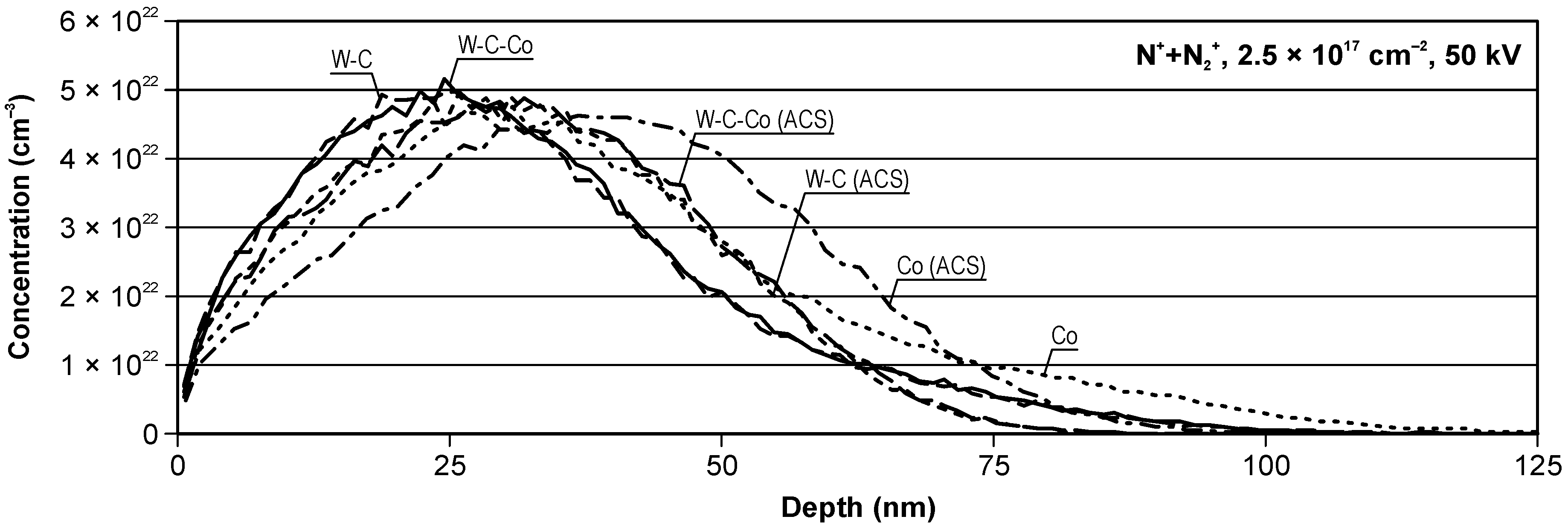
3.1. Results of Modeling Nitrogen Ion Implantation

Figure 9 presents the depth profiles for the cases of N+ + N2+ and ACS in W-C-Co substrate material, for the acceleration voltage of 50 kV and the fluence of 2.5 × 1017 cm−2. All detailed data, i.e., the values of peak volume dopant concentrations, projected range, range straggling, kurtosis and skewness, characterizing the modelled depth profiles of the implanted nitrogen, have been presented in Table 2.
It is evident that N+ + N2+ profiles for W-C-Co and W-C substrates are very similar. The same situation is observed for their ACS. It is also indicated by the very similar values of the parameters shown in Table 2, for both described cases (the data for ACS cases are in the round brackets). This means that in practice, a simpler substrate model for modelling can be adopted, without significantly affecting the results. A greater difference is observed for the Co substrate, both compared to the W-C-Co and W-C substrates, and also to the ACS for Co. However, because this difference is about 7 nm, both for the projected range and range straggling, and cobalt content is only a few percent, this difference can be neglected. The values of the skewness and the kurtosis are higher for the N+ + N2+ case due to the two types of implanted ions. The shift of the peak maximum towards the surface is observed. The ACS profiles are closer to the normal distribution.
The calculated values of sputtering yield are relatively low and again very similar for W-C-Co and W-C substrates. The value of this parameter is about two-fold higher for cobalt. This means that the sputtering of this element will be easier.

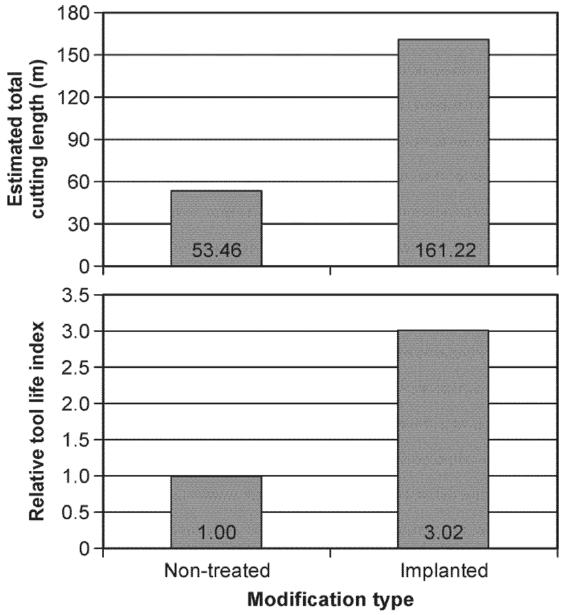
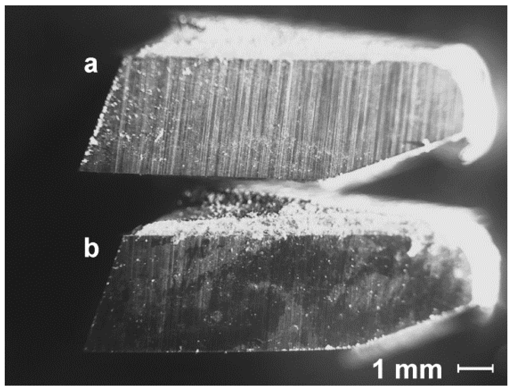
3.2. Wear and Tool Life Analysis
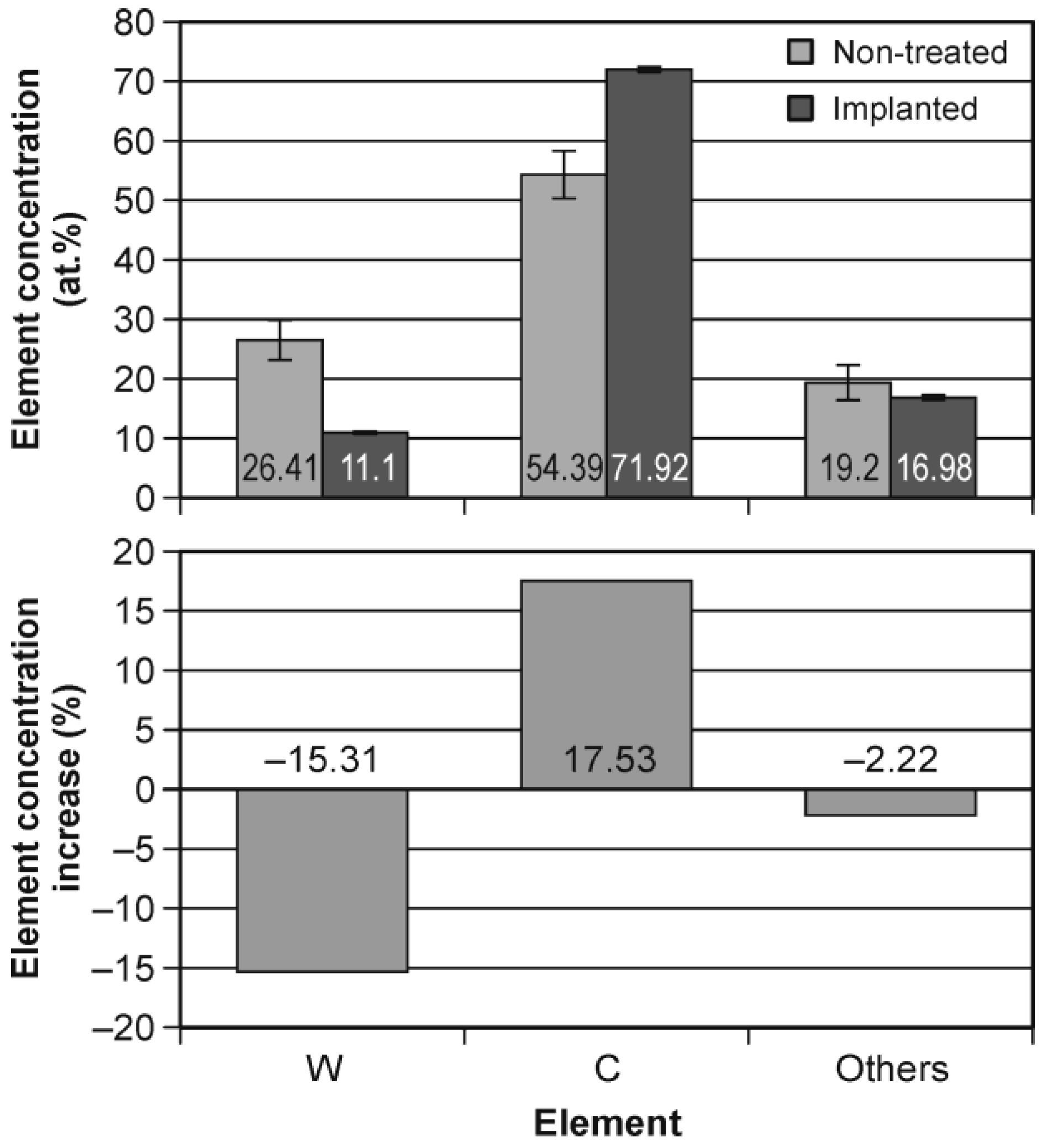
The average value of the measured base indicator of a new saw W ¯ z 0 was 0.09 mm. This indicator was used to calculate the actual wear of a given tooth Z i according to Equation (1). The average wear values of 40 teeth of individual circular saw blades ( Z ¯ i indicator) are presented in Table 3. The same table also shows the total cutting length realized by the circular saw blade. We can see that, in pairs (non-treated and ion-implanted tools), they overcame the same total cutting length. It was consistent with the methodology of industrial research, where two circular saw blades were operated simultaneously on one machine, and their replacement took place on the same total cutting length, based on the poor quality of the machining edges observed by the machine operator, regardless of whether it was for a non-treated tool or for an ion-implanted tool.
Table 3 shows that in two cases, the wear of the ion-implanted circular saw blades is lower than that of the non-treated circular saw blades on the same total cutting length, while in one case the tools were worn evenly. Be aware that tool wear is not yet tool life. To obtain the tool’s life, it was necessary to use the linear function of the estimated linear least squares method (Equation (2)) and calculate the tool life for the adopted blunting criterion (tool life criterion) equal to 0.5 mm. The estimated total cutting length obtained in this way, corresponding to the tool life, is shown in Figure 10.
Figure 10 also shows the value of the relative tool life index calculated according to Equation (3). More than a three times greater estimated lifetime of nitrogen-implanted tools was achieved in relation to non-treated tools. It may be surprising that such a large difference between the estimated tool life is not visible in the measured wear of individual groups of tools. It should be remembered that the increase in wear in the second wear phase (steady-state wear region) on the classic wear curve (Lorenz wear curve—Figure 7) is very slight (slight slope of the linear function), hence even a small difference in the tool wear may result in large disproportions in tool life, and so it was in this case. The above considerations are valid only for comparable cutting regimes because no information about the results obtained in more “aggressive” cutting regimes have been achieved at this moment.
It remains to be decided what causes the lower wear and the increased life of nitrogen ion-implanted tools. Earlier studies indicated a large role of carbon in the shaping of tool life. It was shown that for the W/C ratio below the value of 0.9, the highest cutting length of tools was obtained after nitrogen ion implantation with the energy of 50 keV [1], more than twice as long as the non-treated tools.
Other anti-wear mechanisms that occurred after nitrogen ion implantation were also indicated. Another one is the deformation of the crystal lattice of the implanted material. Foreign nitrogen atoms in the WC-Co material create point defects that inhibit the movement of linear defects called dislocations. Therefore, an atmosphere of dopant atoms (in this case nitrogen), referred to as the Cottrell atmosphere, will be formed along the dislocation line [26]. The Cottrell atmosphere inhibits the dislocation movement, which results in strengthening carbide grains. Generally, it can be said that any disturbance of the crystal lattice increases the strength of the material and decreases its plasticity because both properties depend on the free movement of defects in the material [1].
Tungsten nitrides WN were detected at higher fluences of implanted nitrogen ions 5 × 1017 cm−2 at interstitial phases. It is well known that the hardness of nitrides is lower than the hardness of carbides of the same metals (including tungsten), but at the same time the plasticity of nitrides is higher [27]. Such a change in properties can be beneficial for cutting tools’ exploitation. Under impact conditions (during machining), tools that are less hard but preserve brittleness have a longer lifetime [1].
In EDS analysis of the tool’s surface after machining, another mechanism was indicated that could contribute to reducing the tool’s wear and increasing the tool’s life.

3.3. EDS Analysis

After the tool life tests it was observed with the naked eye that the surface of the ion-implanted teeth of circular saw blades was contaminated with the remains of wood fibers, dust, etc. The teeth of the non-treated circular saw blades were much less dirty. After manual cleaning of the tested tools, a change in colour and a different shade of the ion-implanted tooth surface were visible (Figure 11). After these observations, a decision was made to test the surface of the teeth using a scanning electron microscope (SEM) and EDS measurements.
At the same time, activation of the surface of the implanted saw tooth was observed, manifested by an increase in adhesion and appearance of the secondary structures on the WC-Co surface. During friction, the secondary structures are in different stages of existence and decay. In order for the wear to be stabilized and of minimum intensity, the friction should lead to the creation of a dynamic equilibrium between the removal process and the formation of these structures on the friction surface. The wear will then be mechanochemical. The secondary structures distribute pressure and friction forces, significantly extending the durability of materials in tribological contact. The secondary structures can be related to the self-organization of the friction surface and contribute to the reduction in wear and increase in tool life during cutting [28].
Figure 12 shows the EDS analysis of elements’ concentration on the surface of non-treated and ion-implanted tools after tool life tests, and the elements’ concentration increase between these two groups of tools. The analysis was limited to elements having the largest share in WC-Co material, i.e., tungsten W and carbon C, while the presence of other elements with small shares was taken into account in the total under the name “Others”. The variability ranges (±standard deviation) are also marked in the top bar chart.
The EDS analysis clearly shows an over 17% increase in the share of carbon in ion-implanted tools, mainly at the expense of the share of tungsten. Changes in the share of other elements were not statistically significant. Thus, the secondary structure formed during the machining on the ion-implanted tools was mainly composed of carbon.
Carbon produces a specific friction surface that reduces the coefficient of friction. The phenomenon transforms the dry friction mechanism into the boundary friction. The boundary friction occurs when a thin layer of lubricant separates the surfaces moving relative to each other; there is no liquid friction in the friction pair, yet the value of the friction coefficient and intensity of wear are reduced by 2–3 orders [29].
The unresolved issue is the origin of the carbon from the friction pair of materials: the WC-Co tool or the wood-based workpiece. The first option would indicate the phenomenon of the segregation of atoms on the friction surface caused by thermodiffusion, activated by surface heating due to friction [30]. The second option may indicate the phenomenon of the selective transfer of atoms from the second material of the friction pair as described by Garunkov and Kragelskii (1968) [31]. Undoubtedly, these issues will be the subject of further research by the authors.

4. Conclusions

Based on the results of the research, the following conclusions can be drawn:
  • The teeth of circular saw blades made of WC-Co and nitrogen ion-implanted were less worn than the non-treated teeth of circular saw blades in the industrial production of wooden door frames.
  • The estimated lifetime, using the linear least squares method, of ion-implanted tools was over three times higher than the lifetime of non-treated tools.
  • After tool life tests, secondary structures made of carbon were observed on the surface of ion-implanted tools.

Author Contributions

Conceptualization, J.W. and M.B.; Data curation, J.W., M.B., A.W. and P.F.; Formal analysis, J.W. and M.B.; Funding acquisition, Z.K.; Investigation, J.W., M.B., Z.K., A.W., P.F., M.P., M.D., J.Z., B.S. and T.R.; Methodology, J.W., M.B., J.Z. and B.S.; Project administration, J.W., M.B. and Z.K.; Resources, J.W., M.B., Z.K., A.W., P.F., J.Z. and B.S.; Software, M.B.; Supervision, J.W.; Validation, J.W. and M.B.; Visualization, J.W. and M.B.; Writing—original draft, J.W. and M.B.; Writing—review & editing, Z.K., A.W., P.F., M.P., M.D. and T.R. All authors have read and agreed to the published version of the manuscript.

Funding

This research received no external funding.

Institutional Review Board Statement

Not applicable.

Informed Consent Statement

Not applicable.

Data Availability Statement

Not applicable.

Conflicts of Interest

The authors declare no conflict of interest.

References

  1. Wilkowski, J.; Barlak, M.; Böttger, R.; Werner, Z.; Konarski, P.; Pisarek, M.; Wachowicz, J.; von Borany, J.; Auriga, A. Effect of Nitrogen Ion Implantation on the Life Time of WC-Co Tools Used in Particleboard Milling. Wood Mater. Sci. Eng. 2021, 1–12. [Google Scholar] [CrossRef]
  2. Wilkowski, J.; Górski, J. Vibro-Acoustic Signals a Source of Information about Tool Wear during Laminated Chipboard Milling. Wood Res. 2011, 56, 57–66. [Google Scholar]
  3. Wilkowski, J.; Jegorowa, A.; Barlak, M.; Werner, Z.; Zagórski, J.; Staszkiewicz, B.; Kurek, J.; Kruk, M. Effect of Nitrogen Ion Implantation on the Tool Life Used in Particleboard CNC Drilling. Materials 2022, 15, 3420. [Google Scholar] [CrossRef]
  4. Wilkowski, J.; Barlak, M.; Werner, Z.; Zagórski, J.; Czarniak, P.; Podziewski, P.; Szymanowski, K. Technical Note: Life-Time Improvement and the Cutting Forces in Nitrogen-Implanted Drills during Wood-Based Material Machining. Wood Fiber Sci. 2019, 51, 209–220. [Google Scholar] [CrossRef] [Green Version]
  5. Wilkowski, J.; Barlak, M. The Lifetime of Cemented Carbide Blades during Wood-Based Panels Milling. Biul. Inf. OB-RPPD 2018, 3–4, 118–128. [Google Scholar] [CrossRef]
  6. Zhu, Z.; Guo, X.; Ekevad, M.; Cao, P.; Na, B.; Zhu, N. The Effects of Cutting Parameters and Tool Geometry on Cutting Forces and Tool Wear in Milling High-Density Fiberboard with Ceramic Cutting Tools. Int. J. Adv. Manuf. Technol. 2017, 91, 4033–4041. [Google Scholar] [CrossRef]
  7. Pędzik, M.; Janiszewska, D.; Rogoziński, T. Alternative Lignocellulosic Raw Materials in Particleboard Production: A Review. Ind. Crops Prod. 2021, 174, 114162. [Google Scholar] [CrossRef]
  8. Barlak, M.; Wilkowski, J.; Werner, Z. Ion Implantation Changes of Tribological and Corrosion Resistance Properties of Materials Used in Wood Industry. Ann. WULS. For. Wood Technol. 2016, 94, 19–27. [Google Scholar]
  9. Labidi, C.; Collet, R.; Nouveau, C.; Beer, P.; Nicosia, S.; Djouadi, M.A. Surface Treatments of Tools Used in Industrial Wood Machining. Surf. Coat. Technol. 2005, 200, 118–122. [Google Scholar] [CrossRef]
  10. Warcholiński, B.; Gilewicz, A.; Szymański, W.; Pinkowski, G.; Olik, R. Improvment of Durability of Engineering Tools for Wood. Inżynieria Powierzchni 2011, 2, 73–80. [Google Scholar]
  11. Djouadi, M.A.; Beer, P.; Marchal, R.; Sokolowska, A.; Lambertin, M.; Precht, W.; Nouveau, C. Antiabrasive Coatings: Application for Wood Processing. Surf. Coat. Technol. 1999, 116–119, 508–516. [Google Scholar] [CrossRef]
  12. Barlak, M.; Piekoszewski, J.; Werner, Z.; Pakiela, Z.; Sartowska, B.; Składnik-Sadowska, E.; Walis, L.; Kierzek, J.; Starosta, W.; Kolitsch, A.; et al. The Influence of Distribution of Titanium Alloyed into Carbon Ceramics by the Intense Plasma Pulses on Their Surface Wettability with Liquid Copper. Vacuum 2009, 83, 81–85. [Google Scholar] [CrossRef]
  13. Nowakowska-Langier, K.; Chodun, R.; Nietubyc, R.; Minikayev, R.; Zdunek, K. Dependence of the Specific Features of Two PAPVD Methods: Impulse Plasma Deposition (IPD) and Pulsed Magnetron Sputtering (PMS) on the Structure of Fe-Cu Alloy Layers. Appl. Surf. Sci. 2013, 275, 14–18. [Google Scholar] [CrossRef]
  14. Werner, Z.; Barlak, M.; Ratajczak, R.; Konarski, P.; Markov, A.M.; Heller, R. Electron-Beam Pulse Annealed Ti-Implanted GaP. J. Appl. Phys. 2016, 120, 085103. [Google Scholar] [CrossRef]
  15. Chodun, R.; Nowakowska-Langier, K.; Wicher, B.; Okrasa, S.; Kwiatkowski, R.; Zaloga, D.; Dypa, M.; Zdunek, K. The State of Coating-Substrate Interfacial Region Formed during TiO2 Coating Deposition by Gas Injection Magnetron Sputtering Technique. Surf. Coat. Technol. 2020, 398, 126092. [Google Scholar] [CrossRef]
  16. Kim, K.; Jeong, H. Steam Condensate Behavior and Heat Transfer Performance on Chromium-Ion-Implanted Metal Surfaces. Int. J. Heat Mass Transf. 2019, 136, 681–691. [Google Scholar] [CrossRef]
  17. Cherdhirunkorn, B.; Surakulananta, S.; Tangsritrakul, J.; Hall, D.; Intarasiri, S. The Effect of Nitrogen Ion Implantation on the Physical and Dielectric Properties of Cobalt-Doped PZT Ceramics. Results Phys. 2020, 16, 102851. [Google Scholar] [CrossRef]
  18. Liu, C.X.; Zhang, J.; Lin, S.B.; Yue, Q.Y.; Zheng, R.L.; Guo, J.H. Two-Dimensional Waveguides in Magneto-Optical Glasses Fabricated by Carbon Ion Implantation and Femtosecond Laser Ablation. Opt. Commun. 2021, 495, 127109. [Google Scholar] [CrossRef]
  19. Kavetskyy, T.; Stebeletska, N.; Borc, J.; Kravtsiv, M.; Graz, K.; Šauša, O.; Švajdlenková, H.; Kleinová, A.; Kiv, A.; Tadeush, O.; et al. Long-Range Effect in Ion-Implanted Polymers. Vacuum 2022, 200, 111038. [Google Scholar] [CrossRef]
  20. Laput, O.A.; Zuza, D.A.; Vasenina, I.V.; Savkin, K.P.; Kurzina, I.A. Effect of Silver Ion Implantation on Surface Physicochemical Properties of Composite Materials Based on Polylactic Acid and Hydroxyapatite. Vacuum 2020, 175, 109251. [Google Scholar] [CrossRef]
  21. Wilkowski, J.; Barlak, M. Infinite Life Time of Cutting Tools—Theoretical Considerations in Context of the Relativistic Tribology. Biul. Inf. OB-RPPD 2022, 1–2, 43–58. [Google Scholar] [CrossRef]
  22. Barlak, M.; Wilkowski, J.; Werner, Z.; Staszkiewicz, B.; Zagórski, J. Increasing Technical Capabilities of the Ion Implanter in Tool Modification Processes. Biul. Inf. OB-RPPD 2022, 1–2, 59–82. [Google Scholar] [CrossRef]
  23. Barlak, M.; Wilkowski, J.; Werner, Z. Modelling of Nitrogen Implantation Processes into WC-Co Indexable Knives for Wood-Based Material Machining Using Ion Implanters with or without Direct Ion Beam. Ann. WULS For. Wood Technol. 2019, 108, 68–78. [Google Scholar] [CrossRef]
  24. SRIM. Available online: http://www.srim.org/ (accessed on 28 August 2022).
  25. SUSPRE. Available online: http://uknibc.co.uk/suspre/ (accessed on 28 August 2022).
  26. Yeo, S.; Kim, Y. The Enhancement of Wear Resistance for Nitrogen-Implanted Tungsten Carbide. J. Korean Phys. Soc. 2015, 66, 474–477. [Google Scholar] [CrossRef]
  27. Kupczyk, M.J. Production and Operation of Cutting Tools with Anti-Wear Coatings; Publishing House of Poznań University of Technology: Poznań, Poland, 2009. [Google Scholar]
  28. Kostetskii, B.I.; Zazimko, O.V. Physicochemical Effect of Environment in Process of Self-Organization of Materials during Friction. Mater. Sci. 1990, 26, 650–656. [Google Scholar] [CrossRef]
  29. Shpenkov, G.P. Friction Surface Phenomena; Elsevier: Amsterdam, The Netherlands, 1995. [Google Scholar]
  30. Bakli, B. Surface Phenomena during Adhesion and Friction Interaction; Mashinostroyenie Published House: Moscow, Russia, 1986. [Google Scholar]
  31. Garunkov, D.N.; Kragelski, I.V. Selective Atomic Transfer. Sci. Discov. Diploma 1968, 41, 52–53. [Google Scholar]
Figure 1. Circular saw blade used for investigations (left) and its GSML teeth geometry (right).
Applsci 12 10211 g001
Figure 2. Main view of the ion implanter (left) and view of the circular saw blade’s package inside the implanter vacuum chamber (right).
Applsci 12 10211 g002
Figure 3. Scheme of the ion implantation of circular saw blades used for investigations.
Applsci 12 10211 g003
Figure 4. The pair (non-treated and ion-implanted) circular saw blades during simultaneous work.
Applsci 12 10211 g004
Figure 5. Schemes of cross-section door frame’s components: (a) PS-type door frame, (b) component, (a,c) component E160 type, (d) oblique cut of the door frame.
Applsci 12 10211 g005
Figure 6. Measurement of the direct wear indicator.
Applsci 12 10211 g006
Figure 7. Classic wear curve showing the evolution of wear during machining.
Applsci 12 10211 g007
Figure 8. EDS tests on the tooth surface.
Applsci 12 10211 g008
Figure 9. Modelled nitrogen depth profiles in WC-Co.
Applsci 12 10211 g009
Figure 10. Estimated total cutting length and the relative tool life index for non-treated and ion-implanted circular saw blades.
Applsci 12 10211 g010
Figure 11. Tooth surfaces of circular saw blades: (a) non-treated tool with visible directional grinding after tool sharpening, (b) ion-implanted tool with poorly visible grinding obscured by a darker secondary structure.
Applsci 12 10211 g011
Figure 12. The concentration of elements on the surface of non-treated and ion-implanted tools after tool life tests and percentage increase in elements’ concentration.
Applsci 12 10211 g012
Table 1. Values of acceleration voltage and energy of the nitrogen-implanted ions.
Acceleration Voltage (kV)Percentage Charge State Distribution (%)
N2+N+
6733
Energy (keV)
502550
Table 2. Values of the parameters of nitrogen peak and the sputtering yield.
Implanted SurfacePeak Volume Dopant Concentration
Nmax
(cm−3)
Projected Range
Rp
(nm)
Range Straggling
ΔRp
(nm)
SkewnessKurtosisSputtering Yield
Y
(Atoms/Ion)
W-C-Co5.17 × 102231.637.80.85743.62370.49
(4.89 × 10²²)(31.8)(32.4)(0.2732)(2.5179)(0.48)
W-C4.98 × 102231.337.40.85973.62710.48
(4.93 × 10²²)(31.4)(32)(0.2936)(2.5403)(0.47)
Co4.75 × 102238.144.80.8263.46170.92
(4.63 × 10²²)(38.4)(36.8)(0.1878)(2.5197)(0.87)
The data for ACS cases are in the round brackets.
Table 3. Total cutting length and wear of circular saw blades.
Circular Saw BladeTotal Cutting Length
(m)
Tool Wear Z ¯ i
(mm)
Non-treated 1131.620.67
Non-treated 2104.190.45
Non-treated 3161.320.48
average132.380.53
Ion-implanted 1131.620.56
Ion-implanted 2104.190.45
Ion-implanted 3161.320.47
average132.380.49
Publisher’s Note: MDPI stays neutral with regard to jurisdictional claims in published maps and institutional affiliations.

