Abstract
Corrosion monitoring and management has been at the center of structural health monitoring protocols due to its damaging effects on metallic structures. Current corrosion prevention and management programs often fail to include environmental factors such as Cl− ions and surface wetness. Early detection of these environmental factors can prevent the onset of corrosion and reduce repair and maintenance-related expenses. There is growing interest in creating solution-processed thin film environmental sensors with high sensitivity to corrosion precursors, low-cost fabrication, and small footprint, rendering them viable candidates for investigation as potential corrosion sensors that could be easily integrated into existing structures and screen printed or patterned directly into surface coatings. In this work, we have implemented C60-based n-type organic thin film transistors (OTFTs) with functionalized graphene oxide for humidity sensing and functionalized graphene nanoparticles for Cl− ion detection, using low-cost solution processing techniques. The reduced graphene oxide (rGO)-coated OTFT humidity sensor is designed for the qualitative estimation of surface moisture levels and high levels of humidity, and it exhibits a relative responsivity for dry to surface wetness transition of 122.6% to surface wetness, within a response time of 20 ms. We furthermore implemented an in-house synthesized hydrogenated graphene coating in conjunction with a second OTFT architecture for Cl− ions sensing which yielded a sensitivity of 4%/ppm to ultrafine ionic concentrations, over an order of magnitude lower than the range identified to cause corrosion in aircraft structures.
1. Introduction
Corrosion is an omnipresent problem affecting the integrity of metallic structures and is the most common cause of metal deterioration and failure. Effective prevention and maintenance are of paramount importance to maintaining structural health, safety, and durability [1]. Corrosion in a structure can manifest itself in different forms: from an easily detectable uniform and exfoliating surface to a very hard-to-detect intragranular and pitting form. Furthermore, corrosion can be caused by a variety of physical and environmental factors. Physical factors include cracks and crevices, static and dynamic stress, and coating degradation, whereas environmental factors include exposure to high levels of humidity, temperatures, and salinity [2].
Corrosion monitoring in aircraft structures is an important safety measure due to the nature of in-service conditions that provide auspicious environments for corrosion onset and progression. Currently, aircraft corrosion monitoring and management programs are based on “find and fix” protocols, where corrosion detection relies on visual inspection and mass loss sensors, such as corrosion coupons, electrical resistance, corrosion potential, ultrasonic and acoustic emission, etc. [3]. While such methods provide valuable information about the presence and progression of structural damage, they fail to differentiate between corrosion and cracks, and do not specify the form nor the cause of the detected corrosion. They may detect corrosion damage, but they fail to identify early stages of corrosion and factors responsible for corrosion events, namely changes in pH, metal ions (Fe2+, Co2+, Al3+, Cu2+), changes in humidity, and chloride ions (Cl−) [1,2]. Reliable structural health monitoring requires continuous and early on detection of environmental factors responsible for corrosion events using in situ, non-destructive sensing mechanisms able to detect minute changes in levels and concentrations of the aforementioned environmental conditions. Frequent exposure to chlorides and humidity provides the essential electrochemical conditions favorable to corrosion events [4]. Chloride ion concentration thresholds for corrosion initiation has been identified to be within the range of 100 ppm and 3500 ppm depending on the type of metal alloy, temperature, and pH [5,6]. As such, there is an urgent need for Cl− ion sensing in the aviation industry. Timely detection of chloride ions below corrosion initiation thresholds would allow for the implementation of preventive measures and avoid severe and costly damage. Most Cl− ion detectors predominantly use silicon-based potentiometric sensors, such as ion selective electrodes (ISE) and electrochemical field effect transistors (ChemFET), which rely on ionophore membranes and electrolytic solutions [7,8]. Although such sensors have been able to reach detection limits as low as 3.5 ppb [7], their implementation in environmental sensing, especially in aircraft corrosion monitoring, remains challenging. The main challenge to integrating potentiometric sensors in corrosion monitoring is to maintain the environmental stability of the aqueous/electrolytic solution or the membrane [8,9].
Organic thin film transistor (OTFT) sensors have the potential to fill in the gap in corrosion prevention strategy, improve corrosion management approaches, and safeguard the integrity of metallic structures while reducing repair and maintenance costs. OTFTs rely on carbon-based organic semiconductors and functional surface layers to perform as chemical sensors capable of targeting and detecting specific environmental conditions and chemical species responsible for and indicative of corrosion onset. Compared to other emerging sensing techniques, such as fiber optics and electrochemical sensors, OTFT chemical sensors are more advantageous in terms of robustness, small footprint, low-cost, and energy-efficient fabrication, which is adaptable for large scale production. Furthermore, they exhibit higher sensitivity, faster response time, and low power consumption [10].
Organic semiconductors have been the focus of intensive interest in both the academic and industrial sectors, owing largely to their abundance, solution processability, large-area manufacturing capabilities, mechanical flexibility, and comparable electronic properties compared to their inorganic counterparts. While p-type organic semiconductors have had enormous success in various applications, n-type semiconductor progress has been substantially lagging owing to its environmental instability and low carrier mobility stemming from electron trapping. The performance of n-type OTFTs can be improved by both molecular design and device optimization in term of deposition techniques, passivation, and encapsulation [11]. As a chemically sensitive functional layer, modified graphene has attracted significant attention in recent years owing to its high electrical and thermal conductivity, high carrier mobility, and mechanical flexibility [12]. The solution processability and ease of chemical functionalization of graphene allows for low-cost, large-scale fabrication of thin films with high sensitivity to target analytes.
There have been little to no attempts thus far at designing chloride ion sensors using thin film sensors for structural health monitoring. Our reported work is motivated by this scarcity of reported chloride ion sensors designed specifically for monitoring aircraft corrosion, and utilizing advantages offered by graphene-derived materials in corrosion monitoring. In our work, OTFT humidity and chloride sensors are fabricated using reduced graphene oxide (rGO) and hydrogenated graphene coatings, respectively. rGO is the product of the reduction of graphene oxide, by which GO is partially reduced by the controlled removal of oxygen-containing groups from the surface of GO layers using simple treatments, namely chemical, thermal, and photochemical reduction [13]. This process restores the inherent electrical conductivity of graphene while maintaining the solubility in water and in organic solvents and chemical reactivity characteristic to GO [14]. The sensitivity of rGO to humidity stems from the presence of functional groups at the edges of the graphene layers that bind with water molecules and enhance the conductivity of rGO [15]. Additionally, chemically functionalized hydrogenated graphene coating is used for Cl− ions sensing. There are conceptually two main methods for the synthesis of hydrogenated graphene, namely gas phase approaches, which include plasma hydrogenation and thermal cracking, and wet chemical approaches, such as Birch and electrochemical reduction [16,17]. The hydrogen atoms disrupt the structure of the graphene matrix leading to the hybridization of sp2 bonds into sp3 and the formation of C-H bonds [17]. Although the chemical affinity of hydrogenated graphene has not been considerably investigated, studies suggest that the C-H bonds in hydrogenated graphene may exhibit chemical reactivity and display selectivity toward halide ions, most specifically to Cl− ions [18,19]. The rGO-coated OTFT humidity sensor is designed for qualitative measurements of surface moisture levels, and it is used as a peripheral sensor to ensure the hydrogenated graphene-coated OTFT Cl− ion sensor operates in relatively dry conditions.
2. Materials and Methods
Fullerene C60 (sublimed, 99.9% purity), 1,2 dichlorobenzene, Poly(vinyl alcohol) (PVA), poly(3,4-ethylenedioxythiophene) polystyrene sulfonate (PEDOT:PSS), Sodium:Pottasium alloy (Na-K (1:3)), ethylenediamine, fluorographite, isopropanol, ethanol, and n-hexane were obtained from Sigma Aldrich. Graphene nanoplatelets (GnP) and rGO were acquired from Kennedy Labs and Poly(methyl methacrylate) (PMMA) from DuPont. De-ionized (DI) water was supplied by Carleton University microfabrication lab.
2.1. Preparation of OTFT Humidity and Chloride Ions Sensor
We fabricated a top gate, bottom contact OTFT configuration using fullerene (C60) as the active material and functionalized graphene as the sensory layer, as illustrated in Figure 1b,c.
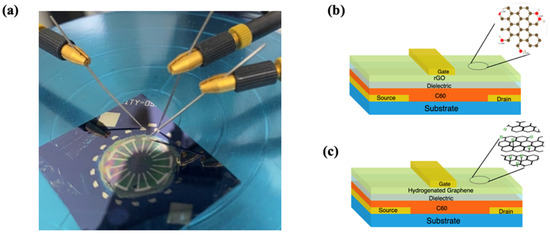
Figure 1.
OTFT environmental sensor. (a) Photographic image of a solution processed C60 OTFT device under test. (b) rGO-based OTFT humidity sensor architecture. (c) Hydrogenated graphene-based OTFT Cl− sensor architecture.
The OTFT sensors were solution processed using layer-by-layer deposition performed under a nitrogen atmosphere in a spin-coating apparatus. The structure materials were spin coated on a passivated silicon substrate on which chromium source and drain electrodes were patterned via UV lithography and negative lift-off. A common core OTFT device structure was fabricated by depositing 0.9% wt. C60 in 1,2-dichlorobenzene, followed by a dielectric stack made of PVA (125 nm) and PMMA (200 nm) and completed by a conductive multilayer composed of PEDOT:PSS (1 μm) and PEDOT:PSS doped with graphene (Gr:PEDOT:PSS) (500 nm). Sensitivity toward humidity and chloride ions was achieved by replacing Gr:PEDOT:PSS by 0.1% suspensions of rGO and hydrogenated graphene in PEDOT:PSS, respectively. Finally, chromium gate metal contacts were deposited through a shadow mask using thermal vapour deposition, as shown in Figure 1a. The device patterning process yielded multiple devices with channel length and width ranging from 10 μm to 25 μm and 100 μm to 1000 μm, respectively, and were fabricated under the same conditions. This allowed for the investigation of device scalability and reproducibility.
2.2. Wet Chemical Synthesis of Hydrogenated Graphene
Hydrogenated graphene was chemically synthesized in-house using a modified Birch method [20]. Briefly, 2.33 g of 1:3 Na-K alloy and 5 mL of ethylenediamine were added into a 50 mL three-necked round-bottomed flask under a nitrogen atmosphere and stirred until a blue mixture was obtained. Meanwhile, a solution of 43 mg of fluorographite in 5 mL of ethylenediamine was sonicated for 30 s. The fluorographite-ethylenediamine suspensions were then added to the flask through a gastight syringe and stirred under a nitrogen atmosphere at room temperature for 2 h. Isopropanol (10 mL) was added using a peristaltic pump at a rate of 5 mL/h until the blue colour disappeared. After the Na-K alloy was completely exhausted, the mixture was dispersed in 50 mL of de-ionized water and extracted with n-hexane, after which the mixture was filtered through a 0.22 μm nylon membrane. After washing the resulting brown cake product alternatively with n-hexane and alcohol, it was dried overnight under vacuum at 60 °C.
2.3. Chemical Characterization of Hydrogenated Graphene
The chemical characterization of hydrogenated graphene was performed using X-ray photoelectron spectroscopy (XPS) and Fourier Transform Infrared Spectroscopy (FTIR). X-ray photoelectron XPS data were collected using AlKα radiation at 1486.69 eV (150 W, 10 mA), a charge neutralizer, and a delay-line detector (DLD) consisting of three multi-channel plates. Survey spectra were recorded from −5 to 1200 eV at a pass energy of 160 eV (number of sweeps: 2) using an energy step size of 1eV and a dwell time of 100 ms to confirm the hydrogenation of the graphene. To further verify the hydrogenation, FTIR was performed on an ABB Bomem MB-Series FTIR spectrometer, with a resolution of 8 cm−1, using a KBr pellet method. Scanning was from 400 to 4000 cm−1.
2.4. Charge Carrier Mobility Characterization
The characterization of the charge carrier mobility of the semiconductor channel was performed using the Dark Injection Space Charge Limited Current (DI SCLC) method, shown in Figure 2. In this configuration, the semiconductor is placed between a blocking electrode and an injecting electrode. A step function is then applied between the electrodes and the resulting transient current is measured. The carrier mobility is calculated using Equation (1), where ttr is the free carrier transient time, V the applied voltage, and d the thickness of the semiconductor film. τDI corresponds to the time it takes for the current to peak and represents the time it takes for the first sheet of charge carriers to reach the counter electrode [21].
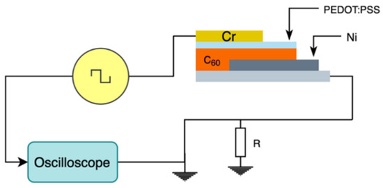
Figure 2.
Schematic of the Dark Injection Space Charge Limited Current measurement setup.
The sample was prepared by depositing a thin film of C60 on a silicon substrate coated with nickel acting as the blocking electrode. A thin film of PEDOT:PSS (~5 nm) was deposited on the C60 film to enhance its conductivity, followed by a chromium layer acting as the charge injecting electrode.
2.5. OTFT Testing and Characterization
The OTFT individual layers thicknesses were measured using cross sectional Scanning Electron Microscopy (SEM) images of the deposited films. The morphology features and surface topology of the sensing films were investigated using Atomic Force Microscopy (AFM).
The OTFT electrical characterization was performed using a probe station and a semiconductor parameter analyzer. All measurements were obtained in a dark and ambient environment to minimize photodegradation. The output characteristic was extracted by sweeping the drain-source voltage VDS from −2 V to 30 V and measuring the drain-source current and the gate leakage current IGS at a constant gate bias of 80 mV, 500 mV and 1 V. The transfer characteristic was obtained by sweeping the gate-source voltage VGS from −1 V to 5 V and measuring IDS at constant drain-source voltages of 50 mV. Output and transfer sweeps were both performed at a step size of 50 mV.
The humidity sensor response was monitored by placing the sensor in a gas chamber equipped with nitrogen gas flow to remove ambient gases before and after exposure to moisture. The sensor was exposed to a high humidity above 80% RH to mimic condensation and surface wetness conditions, sufficient to test the peripheral sensor for wetness detection. The response of the chloride sensor was tested by depositing Cl− ion solutions with varying concentrations on the gate surface and monitoring the change in output current after the complete evaporation of water.
3. Results and Discussion
3.1. Chemical Characterization
Both graphene and in-house synthesized hydrogenated graphene materials were observed using XPS and FTIR, and the peaks in the respective spectra were examined and analyzed. Confirmation of hydrogenation of the graphene was observed in both the XPS and FTIR spectra, as shown in Figure 3a,b. Hydrogenation was confirmed in the XPS spectra where a shift in the C1s spectra is visible from ~284 eV in graphene to ~287 eV in hydrogenated graphene. The peak value in the C1s spectrum (~284 eV) of the tested graphene sample is comparable to the peak values of the spectra reported in literature for pristine graphene [22]. Given that XPS cannot distinguish C–H and C–C bonds, the FTIR transmittance spectra comparison of both graphene and hydrogenated graphene was then used to confirm sp3 C-H hybridization peaks due to C-H stretching vibrations at wave number ~2852.51 cm−1 and ~2923.87 cm−1, and an intense C-H bending peak at ~1122.49 cm−1 on hydrogenated graphene and relatively weaker or completely non-existent on graphene. Using fluorographite as a starting material instead of graphite or graphite oxide contributes to a highly hydrogenated product as, according to a mechanism by Yang et al., the tertiary C-F bond domains are the principal structure of the fluorographite and these can be easily reduced. We can conclude that tertiary C-F bonds in fluorographite were all transformed into C-H bonds as well as C-C π-conjugated domains, but it should be noted that the latter domains form the minor structure of fluorographite [20]. A stronger C-C skeletal vibration at ~1629.73 cm−1 for HG compared to the one on graphene can mean the destruction/displacement/removal/utilization of the C=C during the reduction process and further analysis and or study is beyond the scope of this study. For purposes of this study we have confirmed hydrogenation.
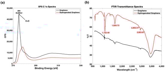
Figure 3.
Characterization results of hydrogenated graphene vs. pristine graphene: (a) XPS C 1s. (b) FTIR Spectra.
3.2. Physical Characterization
Film morphology and uniformity has a significant impact on the performance of the OTFT devices, where uniform films exhibit low sheet resistance, which is highly desirable. Figure 4a–d display AFM images of the surface topography of the C60 OTFT channel layer, graphene:PEDOT:PSS, rGO:PEDOT:PSS, and hydrogenated graphene: PEDOT:PSS, on a 50 μm × 50 μm area, respectively. The AFM image reveals that the spin-coated C60 has a smooth surface with a spot-like crystalline morphology with an RMS roughness (Rq) of 6.67 nm, and mean roughness (Ra) of 5.33 nm. Whereas graphene: PEDOT:PSS, rGO:PEDOT:PSS, and hydrogenated graphene:PEDOT:PSS have an RMS roughness of 7.77 nm, 7.28 nm, and 11.4 nm, and Ra of 5.68 nm, 4.24 nm, and 8.46 nm, respectively.

Figure 4.
(a–d) AFM 2D and 3D surface topology images of (a) C60, (b) graphene:PEDOT:PSS, (c) rGO:PEDOT:PSS, (d) Hydrogenated graphene:PEDOT:PSS, (e) SEM cross sectional images of spin- coated C60 layer.
The conductive/sensing layers show a relatively smooth surface with apparent peaks corresponding to the doping agent flakes (Gr, rGO, and hydrogenated graphene), indicating that PEDOT:PSS results in smooth conductive layers.
The thickness of the OTFT individual structural layers was determined using SEM, as shown in Figure 4e, which displays the C60 channel layer deposited on the SiO2/Si substrate. The thicknesses of the other structural layers was estimated using the same approach. The measured OTFT structural layers thicknesses were 120 nm, 125 nm, 200 nm, 1000 nm, and 500 nm for C60, PVA, PMMA, PEDOT:PSS, and Gr:PEDOT:PSS, respectively.
The thicknesses of the spin-coated rGO:PEDOT:PSS and hydrogenated graphene: PEDOT:PSS films were both measured at ~500 nm.
3.3. Charge Carrier Mobility Characterization
The charge carrier mobility was measured using the DI SCLC methodology which gives direct measurements of charge mobility in C60. Figure 5a displays the current transient of the C60 film at different voltages, where a rapid increase in the current can be observed as the applied voltage increases, reaching a point where the charge density is maximized. The well-defined maxima
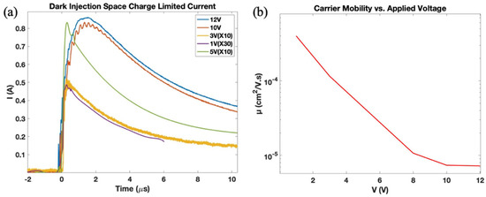
Figure 5.
Charge mobility characterization: (a) SCLC current transient, (b) measured charge mobility vs. applied voltage.
observed in Figure 5a indicates the arrival time of the fastest charge carriers to the non-injecting contact. Beyond that point, the current density decreases until it reaches the equilibrium state analogous to charge dynamic equilibrium. The observed increase in current transient with increasing voltage featuring a shift of the current peak to lower values is indicative of the formation of ohmic contact typical to DI SCLC transients. Figure 5b summarizes the electron mobilities obtained from Dark Injection Space Charge Limited Current measurements showing higher mobilities in the low voltage region and a saturation region at higher voltages, suggesting that electron mobility becomes independent of the applied voltage. These results were valuable in confirming the semiconducting behaviour of our solution-processed C60 film and furthermore helped in setting an optimal voltage bias point for the reported OTFT-based sensors.
3.4. Current-Voltage Characterization
The output and transfer characteristic of the OTFTs with graphene:PEDOT:PSS as the top gate conductive layer is shown in Figure 6a,c. OTFTs exhibit a clear n-type transistor behaviour and possess a demonstrable linear and saturation region at higher gate bias voltages, along with very low gate leakage current IGS. Figure 6b shows the scalability of the OTFT where the output characteristic of OTFTs with different aspect ratios were compared showing increasing output current with increasing aspect ratios. Device metrics, namely threshold voltage, carrier mobility, and ON/OFF ratio were determined from the transfer characteristic data displayed in Figure 6c. The effective per unit area dielectric capacitance was measured directly using a precision impedance analyzer and valued at 7.82 nF/cm2. The threshold voltage Vth = 1.2 V was determined graphically. The corresponding charge carrier mobility and ON/OFF ratio were evaluated at VDS = 50 mV and estimated as 1.2 cm2/V s and 3.75 × 10², respectively.
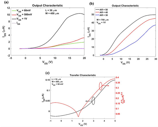
Figure 6.
OTFT electrical characterization results: (a) Output characteristic at constant gate bias VGS range from 80 mV to 1 V, (b) parametric sweep of output characteristic against OTFT aspect ratio at VGS = 1 V, (c) transfer characteristic at VDS = 50 mV where IDS and √IDS are used for estimating threshold voltage, carrier mobility, and current ON/OFF ratio.
The OTFT devices exhibited good characteristics and relative environmental stability in ambient conditions. The gate leakage current was very low compared to the drain-source current, which is indicative of low surface defects of the semiconductor layer, good dielectric/semiconductor interface, and the high quality of the dielectric stack. As expected, characteristics of devices fabricated using the same process vary due to variations in ambient conditions, film thickness, and morphology. The fabricated OTFT devices experience drift and decreasing drain current with repeated measurements but remain operational over several weeks using the same device.
3.5. Sensor Performance
3.5.1. OTFT Humidity Sensor
The use of rGO as humidity sensing material for OTFTs is based on its conductive nature and its chemical affinity toward water molecules [15]. The humidity OTFT sensor was designed for qualitative measurement purposes to detect the presence of surface moisture. It is used in conjunction with the chloride sensor to ensure the latter operates in dry conditions only to minimize false measurements.
In this instance, the OTFT gate was functionalized with rGO which undergoes an increase in conductivity in the presence of water molecules. The sensor’s transient response was measured at a constant gate bias of 1 V and drain voltage of 5 V at which the OTFT operates in the linear regime. The current transient of the sensor is depicted in Figure 7a, which displays the sensors response before, during, and after exposure to high levels of humidity.
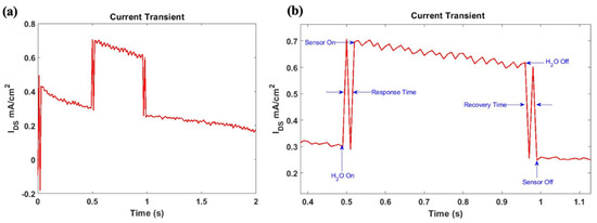
Figure 7.
(a) Transient response from OTFT humidity sensor before, during and after exposure to surface wetness with device architecture: L = 15 μm and W = 300 μm. (b) Humidity sensor response illustrating the current transient, response time, and recovery time of the sensor.
As expected, the conductivity of rGO is enhanced as a result of chemical bonding between the hydroxyl groups present in rGO and water molecules. As a result, the sensor output current increases when it is exposed to humidity and the associated relative responsivity for dry to surface wetness transition (RRel) was estimated at 122.6% using Equation (2), where ΔIresp is the change in the sensor current due to exposure to surface wetness and Idry is the sensor output current under dry conditions. The sensor’s response time and recovery time were extracted from the sensor’s response shown in Figure 7b and were both estimated at 20 ms.
Repeated measurements of the sensor transient response revealed that the sensor remains responsive during recurrent exposure to humidity with an unchanged response time. However, the OTFT output current decreased with repeated measurements. This is an expected behaviour of organic thin film transistors as they are prone to environmental doping, material degradation, as well as photodegradation.
3.5.2. OTFT Chloride Ion Sensor
As previously described, the chloride sensor is composed of the C60 OTFT in which the gate conductive layer was functionalized with hydrogenated graphene. The sensing performance of the fabricated OTFT chloride sensor against a broad range of chloride ion concentrations is evaluated and compared to the core OTFT device comprising Gr: PEDOT:PSS as the gate conductive layer. Figure 8a displays the output characteristic of the chloride sensor before and after exposure to different Cl− concentrations (3 ppm −75 ppm) at a constant gate bias VGS = 1 V. As evident, the sensor undergoes a decrease in the saturation current associated with the decrease in conductivity resulting from hydrogenated graphene bonding with chloride ions. The output current was also measured at VDS = 13 V, during which the sensor operates in the linear regime. Transistors with varying channel lengths and aspect ratios were exposed to Cl− solution and their output current was measured. For all OTFT Cl− sensors, the output current density exhibits a logarithmic dependence over concentration ranging between 3 ppm and 75 ppm, as shown in Figure 8b. Transistor dimension variations do not affect responses to seen analytes, where changes in IDS remain consistent regardless of the sensor’s surface area. The sensor response experiences slight diversion after recurring measurements, often observed on organic electronics, but remains relatively uniform with respect to analyte concentration.
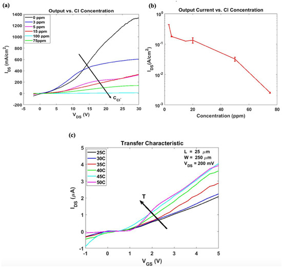
Figure 8.
Hydrogenated graphene-based OTFT Sensor Performance: (a) Output characteristic at fixed VGS of 1 V at different chloride ion concentration, (b) logarithmic sensor response vs. chloride ion concentration at VGS 1 V and VDS 13 V. (c) Sensor′s temperature drift.
The sensitivity of the sensor was estimated at 4%/ppm and was calculated using Equation (3), where ΔIresp is the change in the output current after exposure to Cl−, Iref is the baseline output current, and C is the Cl− concentration.
For practical application of environmental sensors, they typically need to operate in environments where the temperature may vary significantly. The temperature dependence of the OTFT sensor was investigated by placing the OTFT on a Peltier cooler-regulated thermal chuck and the drain current versus the gate voltage dependence was plotted at a constant drain-source voltage of 200 mV. Sensor response to increasing temperature is depicted in Figure 8c, which shows the expected increase in the drain current attributed to thermal effects. The thermal effects’ influence on the sensor operation appears as a decrease in the threshold voltage (0.2 V to 0.05 V), although not significant, it should be taken into consideration. The mobility, on the other hand, undergoes an increase of ~70% as the temperature is increased from 25 °C to 45 °C.
It was demonstrated that the in-house synthesized hydrogenated graphene displays chemical affinity toward Cl− ions which results in a decrease in electrical conductivity. This was achieved using C60 OTFT as a transducer which experiences a decrease in output current as hydrogenated graphene is exposed to Cl−. Our Cl− ions sensor is able to detect small concentrations far below reported corrosion initiation thresholds of 100 ppm to 3500 ppm [5,6]. Investigation of device scalability demonstrates the achievability of a miniaturized Cl− sensor without compromising the reliability of the measurements. Regardless of variation in the transistor dimensions, measurements of % change in output current in response to Cl− concentration are consistent and repeatable.
OTFT sensors experience drift and decreasing drain current with repeated measurements but remain operational over several weeks using the same device. Despite these variations, the OTFT was used to fabricate chloride ion and humidity sensors with robust response to minute concentrations.
Currently, the fabricated sensors are at the development stage and were tested in a laboratory environment without encapsulation and packaging. Further improvements are currently in progress and it is the aim to implement drift correction measures by limiting exposure to contaminants during fabrication, implementing temperature drift compensation, and designing proper encapsulation and packaging.
4. Conclusions and Future Work
N-type OTFT was successfully fabricated using solution deposition techniques with fullerene C60 as the semiconductor channel and was used in the fabrication of humidity and chloride ions sensors for corrosion monitoring applications. The OTFT has low threshold voltage, large charge carrier mobility, and good current ON/OFF ratio. Furthermore, it has low power requirement, relative environmental stability, and experiences little to no losses. Hydrogenated graphene was successfully synthesized using the Birch method and was used along with rGO as the sensing materials for chloride ion and humidity sensors, respectively. The organic sensors exhibit high sensitivity to target analytes, low power requirements, and excellent repeatability. The humidity sensor shows an almost instant response to the presence of surface moisture and very fast recovery. The chloride ion sensor can detect very low concentrations compared to corrosion initiation thresholds. This further proves the chemical affinity of hydrogenated graphene toward Cl−. These simple devices are reliable and economically attractive candidates for corrosion prevention techniques and can be the starting point for the design and fabrication of a range of OTFT sensors integrated in common sensor nodes and targeting corrosion precursors and early on by-products. Each sensor node includes a humidity sensor to ensure that the adjacent sensors operate in dry conditions only, and prevent the likelihood of errors and false measurements stemming from sensing in humid conditions. This study demonstrates the potential of solution-processed n-type organic thin film transistor sensors using graphene derived materials in non-destructive inspection for structural health monitoring applications. However, further research and optimization are needed for the realization of robust, environmentally stable, and reliable fully organic corrosion sensors.
Author Contributions
Conceptualization, R.P. and M.C.; Methodology, M.C., S.B. and R.P.; validation, M.C. and R.P.; formal analysis, M.C.; investigation, M.C. and R.P.; resources, R.P.; writing—original draft preparation, M.C., S.B. and R.P.; writing—review and editing, R.P. and M.C.; visualization, M.C.; supervision, R.P.; project administration, R.P.; funding acquisition, R.P. All authors have read and agreed to the published version of the manuscript.
Funding
This research was funded in part by the NSERC Discovery grant [#2018-04154] and the NRC research contract [#9555842]. The APC was funded by NSERC Discovery grant [#2018-04154].
Acknowledgments
The authors acknowledge the financial support from National Research Council (NRC) of Canada and NSERC Canada. The authors are thankful to Lucy Li (NRC Ottawa) for her guidance towards identifying corrosion precursors of concern to the aircraft industry.
Conflicts of Interest
The authors declare no conflict of interest.
References
- Li, L.; Chakik, M.; Prakash, R. A review of corrosion in aircraft structures and graphene-based sensors for Advanced Corrosion Monitoring. Sensors 2021, 21, 2908. [Google Scholar] [CrossRef]
- Roberge, P. Handbook of Corrosion Engineering; McGraw-Hill: New York, NY, USA, 2000. [Google Scholar]
- Wright, R.F.; Lu, P.; Devkota, J.; Lu, F.; Ziomek-Moroz, M.; Ohodnicki, P.R. Corrosion sensors for structural health monitoring of oil and Natural Gas Infrastructure: A Review. Sensors 2019, 19, 3964. [Google Scholar] [CrossRef] [PubMed] [Green Version]
- Rinaldi, G.; Huber, T.; McIntosh, H.; Lebrun, L.; Ding, H.; Weber, J. Corrosion sensor development for condition-based maintenance of aircraft. Int. J. Aerosp. Eng. 2021, 2012, 684024. [Google Scholar] [CrossRef]
- Zhou, W. Effect of a high concentration of chloride ions on the corrosion behaviour of X80 pipeline steel in 0.5 mol L−1 nahco3 solutions. Int. J. Electrochem. Sci. 2017, 13, 1283–1292. [Google Scholar] [CrossRef]
- Hurley, M.F.; Scully, J.R. Threshold chloride concentrations of selected corrosion-resistant rebar materials compared to Carbon Steel. Corrosion 2005, 62, 892–904. [Google Scholar] [CrossRef]
- Ke, X. Micro-fabricated electrochemical chloride ion sensors: From the present to the future. Talanta 2020, 211, 120734. [Google Scholar] [CrossRef] [PubMed]
- Fakih, I.; Durnan, O.; Mahvash, F.; Napal, I.; Centeno, A.; Zurutuza, A.; Yargeau, V.; Szkopek, T. Selective ion sensing with high resolution large area graphene field effect transistor arrays. Nat. Commun. 2020, 11, 1–12. [Google Scholar] [CrossRef]
- Wang, G.Y.; Lian, K.; Chu, T.-Y. Electrolyte-gated Field Effect Transistors in biological sensing: A survey of electrolytes. IEEE J. Electron Devices Soc. 2021, 9, 939–950. [Google Scholar] [CrossRef]
- Lowe, B.M.; Sun, K.; Zeimpekis, I.; Skylaris, C.-K.; Green, N.G. Field-effect sensors—From ph sensing to biosensing: Sensitivity enhancement using streptavidin–biotin as a model system. Analyst 2017, 142, 4173–4200. [Google Scholar] [CrossRef] [Green Version]
- Anthony, J.E.; Facchetti, A.; Heeney, M.; Marder, S.R.; Zhan, X. N-type organic semiconductors in Organic Electronics. Adv. Mater. 2010, 22, 3876–3892. [Google Scholar] [CrossRef]
- Coroş, M.; Pruneanu, S.; Stefan-van Staden, R.-I. Review—recent progress in the graphene-based electrochemical sensors and Biosensors. J. Electrochem. Soc. 2020, 167, 037582. [Google Scholar] [CrossRef] [Green Version]
- Liang, R.; Luo, A.; Zhang, Z.; Li, Z.; Han, C.; Wu, W. Research progress of graphene-based flexible humidity sensor. Sensors 2020, 20, 5601. [Google Scholar] [CrossRef]
- Nurazzi, N.M.; Abdullah, N.; Demon, S.Z.; Halim, N.A.; Azmi, A.F.; Knight, V.F.; Mohamad, I.S. The frontiers of functionalized graphene-based nanocomposites as chemical sensors. Nanotechnol. Rev. 2021, 10, 330–369. [Google Scholar] [CrossRef]
- Lv, C.; Hu, C.; Luo, J.; Liu, S.; Qiao, Y.; Zhang, Z.; Song, J.; Shi, Y.; Cai, J.; Watanabe, A. Recent advances in graphene-based humidity sensors. Nanomaterials 2019, 9, 422. [Google Scholar] [CrossRef] [PubMed] [Green Version]
- Fei, Y.; Fang, S.; Hu, Y.H. Synthesis, properties and potential applications of hydrogenated graphene. Chem. Eng. J. 2020, 397, 125408. [Google Scholar] [CrossRef]
- Yan, L.; Zheng, Y.B.; Zhao, F.; Li, S.; Gao, X.; Xu, B.; Weiss, P.S.; Zhao, Y. Chemistry and physics of a single atomic layer: Strategies and challenges for functionalization of graphene and graphene-based materials. Chem. Soc. Rev. 2012, 41, 97–114. [Google Scholar] [CrossRef] [PubMed]
- Whitener, K.E.; Lee, W.-K.; Stine, R.; Tamanaha, C.R.; Kidwell, D.A.; Robinson, J.T.; Sheehan, P.E. Activation of radical addition to graphene by chemical hydrogenation. RSC Adv. 2016, 6, 93356–93362. [Google Scholar] [CrossRef]
- Tagliazucchi, M.; Szleifer, I. Transport mechanisms in nanopores and nanochannels: Can we mimic nature? Mater. Today 2015, 18, 131–142. [Google Scholar] [CrossRef]
- Yang, Y.; Li, Y.; Huang, Z.; Huang, X. (c1.04h)n: A nearly perfect pure Graphane. Carbon 2016, 107, 154–161. [Google Scholar] [CrossRef]
- Kokil, A.; Yang, K.; Kumar, J. Techniques for characterization of charge carrier mobility in organic semiconductors. J. Polym. Sci. Part B Polym. Phys. 2012, 50, 1130–1144. [Google Scholar] [CrossRef]
- Gao, G.; Liu, D.; Tang, S.; Huang, C.; He, M.; Guo, Y.; Sun, X.; Gao, B. Heat-initiated chemical functionalization of graphene. Sci. Rep. 2016, 6, 1–8. [Google Scholar] [CrossRef] [PubMed] [Green Version]
Publisher’s Note: MDPI stays neutral with regard to jurisdictional claims in published maps and institutional affiliations. |
© 2022 by the authors. Licensee MDPI, Basel, Switzerland. This article is an open access article distributed under the terms and conditions of the Creative Commons Attribution (CC BY) license (https://creativecommons.org/licenses/by/4.0/).