1. Introduction
Global energy consumption has increased drastically in the last few decades. According to the British Petroleum Company plc (BP) statistical review of world energy, the worldwide use of energy has increased approximately by
in the last twenty years [
1]. Fossil fuels such as coal and oil play a major role in fulfilling the global energy demand [
2]. In 2018, more than
of primary energy was generated from fossil fuels [
1]. Energy generation through conventional sources can have environmental issues and the present consumption rate of conventional fuels may cause hindrance in energy generation. Therefore, a transformation of the energy system from conventional fuels is required to meet the global energy need and also to reduce greenhouse gas emissions to 80–90% by 2050 compared to 1990. The key development of renewable energy sources such as wind power is transforming the energy system by providing an alternative and climate-friendly energy source that can meet the global energy demand. In the last twenty years, the installation capacity of the onshore wind turbine has increased from 24 GW to 700 GW [
3]. This enormous growth rate over two decades and specifically the growth rate of
between 2019 and 2020 can make wind energy one of the major players in achieving the net-zero target set by different countries. Despite this enormous development in wind power installation capacity, the current wind turbine installation rate is insufficient for achieving the decarbonization goal by 2050 [
3]. Low-frequency sound emission are more prominent in larger wind turbines [
4] and the size of wind turbines is increasing gradually to maximize the output, which, in turn, can reduce the cost of renewable energy. Few studies [
5,
6,
7] have shown that headache, sleep deprivation, irritability, and fatigue can be the consequences of the sound emission from the wind turbine. Hence, it is important to consider the acceptance of the nearby living population to wind turbine sound emissions for the development process of onshore wind farms. Therefore, for the further expansion of onshore wind farms, it becomes necessary to reduce the low-frequency vibration and sound emissions from an onshore wind turbine.
A study has shown that
of the residents living within 204 m of the nearest wind turbine perceive the sound emissions disturbing [
8]. The same amount of disruption is also felt by
of residents living in the proximity of up to 1728 m [
8]. Hence, to define an onshore wind turbine sound emission limit different regulations exist in each country. The sound emission threshold limit in Germany varies according to area type and between day and night time, see
Table 1. In contrast, the wind turbine sound emissions limit in the Netherlands is not based on different area types but is based on the annual average sound emission, which is calculated by the local wind condition [
9]. In Denmark, the regulation of sound emission from a wind turbine is based on two different wind speeds, namely: 6 m/s and 8 m/s [
9]. Violation of these regulations can result in strong regulatory penalties. It can also lead to imposing restrictions on the running speed of the wind turbine and also the operation time during the night. Hence, reducing the sound emission from wind turbine components is one of the major concerns of manufacturers.
Sound emissions of a wind turbine are generated due to the relative motion of its mechanical components and the dynamic response within these components. Prominent sources of sound radiation are the gearbox and generator. The vibration in the generator is caused by the electromagnetic interactions between the spinning poles of the rotor and the stator. The vibration caused by the generator is transmitted along other structural components, such as the rotor blades, and then it is radiated into the air.
In general, there are two different approaches to reduce the vibration amplitude from a mechanical structure, namely: active vibration control and passive vibration control. However, no requirement of external power, the cost-effectiveness, and robust nature of the passive vibration control system make this technique more favorable for industrial applications. Passive dampers are widely applied in the automotive, aerospace industry [
10], and rail noise control [
11]. Passive dampers, like viscous dampers, find their application in the aerospace industry, submarine, civil structures, and other mechanical structures to suppress the shock waves and vibration [
12]. Wang et al. [
13] have carried out numerical studies to analyze the effect of the viscoelastic damping layer in a wind turbine blade. It has been found that the viscoelastic damping layers, which was attached inside of carbon layer can show a significant reduction in vibration amplitude of carbon fiber wind turbine blade. The damping characteristic of the viscoelastic dampers depends on excitation frequency. Furthermore, viscoelastic dampers can lose their damping efficiency at extremely low or high temperatures. Tuned mass damper (TMD) is a passive control device that is widely applied to reduce the vibration, wind-induced vibrations, and noise from several mechanical and civil structure [
11,
14]. Although TMDs are useful for mitigating the resonance, their mass, stiffness, and damping properties can influence their performance [
14]. To optimize the TMD parameters, a non-linear control target and a new optimization procedure have been suggested in [
14]. However, TMDs are not very appropriate for wind turbines because wind turbines possess a high number of eigenfrequencies below 355 Hz and TMDS are effective in a small range around their resonance frequency. A comparison between the optimal TMD and a suspended particle damper is investigated by Ma et al. [
15]. They have shown that a suspended particle damper when attached to a
MW wind turbine tower performs better than that of TMD for the de-tuned case. Furthermore, it has been concluded that the suspended particle damper is significantly more robust in comparison to the optimal TMD.
In the current contribution, the focus is on the application of a passive vibration and sound reduction concept of the wind turbine generator without influencing the performance of the wind turbine. This paper aims to use particle dampers to reduce low-frequency vibration amplitude from an onshore wind turbine generator. The damping characteristics of particle dampers are highly dependent on particle materials, particle size, as well as on the shape and texture of particles [
16,
17,
18]. Furthermore, packing ratio is also one of the major parameters for analyzing the damping behavior of a particle damper [
16,
17,
18]. This shows that the behavior of particle dampers is highly non-linear. The current article introduces a honeycomb damping plate (HCDP) concept to evaluate the transmission path damping of a wind turbine generator. The developed HCDP cells are partially filled with granular materials, which are then mounted at different positions on wind turbine stator (WTS) test specimen to study their influence in reducing the vibration amplitude of the structure. The decision for filling the HCDP partially and not the whole volume was based on a previous study [
17]. For the experimental investigation of this concept at a lab scale, a laser scanning vibrometer (LSV) device has been used. The current work shows that the developed HCDP concept is suitable for reducing the vibration from a wind turbine generator.
This paper is organized into six sections. In
Section 2, an overview of particle damper applications is presented. The detailed design concept of the WTS test specimen and HCDP is discussed in
Section 3.
Section 4 is dedicated to the experimental setup followed by experimental results in
Section 5. Finally,
Section 6 contains the summary of this work.
2. Application of Particle Dampers
Particle damping technology is conceptual simple, robust, low-maintenance, and cost-effective, which make this technique extremely attractive for industrial application. The ability of particle dampers to sustain under harsh environments and its damping characteristics over a wide range of frequency and temperature makes its application more favorable in comparison to conventional passive dampers and active damping techniques. Moreover, particle dampers are easily recyclable or can be reused depending on the granular materials. In the ongoing project, it has been shown that the waste of automobile tires can be used in particle dampers for a wind turbine blade vibration attenuation [
18].
Veeramuthuvel et al. [
19] have attached a particle damper capsule on a printed circuit board (PCB), which is used in a spacecraft. Authors have used tungsten carbide, stainless steel, and aluminium alloy as granular materials. In their investigation, it has been observed that materials with higher densities are more efficient for vibration attenuation. Authors have found the packing ratio of
effective for vibration suppression for all the materials they have investigated. Furthermore, they have observed that irrespective of granular materials, the packing ratio of
is not effective for reducing the vibration amplitude. A very similar effect of filling ratio on vibration reduction has been also observed in our previous study [
17]. The effectiveness of particle dampers to reduce the vibration amplitude from a spacecraft cantilever beam type appendages was investigated experimentally by Simonian [
20]. A small cavity box containing 30 g lead shot, which was attached to the main structure at the position with the highest deflection during flight, reduces the vibration amplitude significantly under random vibration. He has concluded that in comparison to conventional damping materials, such as viscoelastic materials or viscous fluids, particle dampers are more suitable for spacecraft applications due to their immense damping performance for higher vibration amplitude and also for their insensitive nature towards extreme temperature. Ahmad et al. [
16] have filled the tip of a honeycomb beam with acrylic balls (
mm radius) to investigate the efficiency of particle damping technique on vibration attenuation. The reason for choosing only the tip of the beam for the granular material filling was to keep the additional mass as low as possible. Apart from this, the tip of the beam experiences significant motion for all the bending modes, which makes this area suitable for placing the particle damper. In their investigation, they have found a significant reduction in vibration of the primary structure. The experimental investigation of Michon et al. [
21] has shown that using hollow soft viscoelastic particles can reduce the vibration amplitude of a honeycomb beam. Implementation of soft hollow particles can also be useful in reducing the additional mass coming from granular materials. The authors have investigated three filling ratios, namely:
,
, and
. They found that the filling ratio of
has more influence on the damping ratio. In an experimental study, Els [
22] has shown that the steel ball-bearing can reduce the vibration amplitude significantly when attached to the tip of a rotating cantilever beam. Liu et al. [
23] have shown the usefulness of hollow glass microspheres in reducing the vibration amplitude of a composite honeycomb beam. They have studied the influence of the packing ratios of
,
, and
on vibration attenuation and found that the frequency response of the main structure decreases as the packing ratio increases. Wang et al. [
24] have used tungsten carbide and lead sphere to reduce the vibration amplitude from a precision instrument in spacecraft. In their investigation, it has been shown that the filling ratio of
is more efficient for reducing the vibration amplitude of the primary structure in comparison to the filling ratio of
and
. Like Veeramuthuvel et al. [
19], they have also reported that the particle damper with a higher density is more effective for vibration attenuation.
The application of particle dampers in the automotive industry can be seen in the work of Duvigneau et al. [
25]. In their investigation, it has been shown that sand particles are effective for broadband vibration attenuation of an automotive engine oil pan. The authors have also shown that the particle damping mechanism and not the additional mass is the main reason for the oil pan vibration attenuation. Furthermore, it has been demonstrated that the position of the granular materials plays a major role in reducing the vibration amplitude. In their investigation, they have observed that the damping behavior of the structure can not be improved tremendously just by increasing the amount of sand in the cavity. The influence of granular material distribution for reducing the vibration amplitude of an oil pan has been experimentally investigated by Koch et al. [
17]. For this purpose, the authors have replaced the original bottom of the oil pan with a honeycomb bottom. The experimental observation shows that filling the granular materials at the position with the highest vibration amplitude is the best choice for vibration attenuation. Furthermore, the authors have studied the influence of sand with three different particle size distributions and observed that the larger grain size distribution is more efficient in reducing the vibration amplitude. They have concluded that the uniform distribution of the granular materials also shows remarkable results. This uniform distribution approach can be implemented if the vibration behavior of the primary structure is unknown, which is also a less mass-efficient solution. The study has also shown that the granular material distribution pattern obtained numerically is as powerful as the optimal distribution obtained experimentally. The authors have also demonstrated the efficiency of a partially filled honeycomb structure in reducing the vibration amplitude and sound emission of a running engine. In the proceeding investigations, the project team has studied the influence of different granular materials for reducing the vibration amplitude in general [
26], as well as in the context of a wind turbine blade structure [
18]. The experimental observation shows that rubber granulate is more effective for damping the wind turbine blade test specimen than stone powder and plastic balls. Furthermore, rubber granulate with four different grain sizes has been experimentally investigated to study the effect of the particle size on vibration attenuation. The experimental observation shows that rubber granulate with a larger particle size is more effective for vibration amplitude reduction in comparison to the rubber granulate with smaller particle size. In another study [
26], it has been shown that particle dampers are more effective in reducing the vibration amplitude of the primary structure of an electric engine in comparison to several acoustic damping foam materials. Another automotive application of particle damping to reduce the noise and vibration of electric motors was developed by Simonian [
20]. The author has specifically designed a particle damper to suppress the high-frequency torsional vibration mode of a motor. His investigation shows that the currently used expensive elastomeric tuned mass damper can be replaced with a cost-effective particle damper. Implementation of particle dampers in a mining truck can be seen in the work of Liming et al. [
27]. In their study, it has been observed that particle dampers can reduce the vibration amplitude of the structure more effectively for a higher engine speed. Xu et al. [
28] have successfully used tungsten particles of diameter
mm on a commercial banknote processing machine. Their experimental observation shows that the tungsten particles are effective for the frequency range between 2 kHz to 12 kHz. Xiao et al. [
29] have studied the influence of particle dampers for reducing gear system noise and vibration under centrifugal load. For their experimental investigation, they chose a spur gear with 24 teeth. Eight via holes (each of 15 mm diameter) were drilled in the gear that contains the stainless steel balls of radius 3 mm. They have investigated the influence of their particle damper for three different rotational speeds. They have observed that under a constant loading scenario, the particle damper is more effective at a higher rotational speed. They have also found that the optimal filling ratio depends on the rotational speed of the gear. Heckel et al. [
30] show that steel beads of diameter 2 mm reduce the vibration amplitude of an oscillatory saw. Kumar et al. [
31] have used copper and lead particles to attenuate the vibration amplitude in a boring bar. They have shown that the damping performance of copper particles is higher than by using lead particle. They have also observed that the particles with a larger size are more effective for damping the structure. Jehring et al. have developed a particle-filled metal hollow spheres concept to damp the structure-borne sound [
32]. Jehring has also investigated the influence of mass ratio, particle size distribution, and cavities size on vibration attenuation [
33]. Goehler et al. [
34] have replaced the conventional steel sheets of a milling slide with particle-filled hollow sphere sandwiches to reduce the vibration amplitude. The authors have shown that in comparison to the conventional approach, the particle-filled metal hollow spheres approach increases the damping by factor 5. This approach doubles the stiffness of the primary structure and the mass of the structure can be reduced by
. Chen et al. [
35] have designed a particle damper based on a 2 MW wind turbine with a hub height of 100 m. The authors have used steel balls of radius 55 mm as particle damper that is enclosed in a container made of glass fiber-reinforced plastic. They have observed an approximate linear relationship between the damping effect and the damper mass ratio. Stauber et al. [
36] have investigated the effect of elastomer particles with rough and textured surfaces to reduce the tonal sound emission from wind turbine towers. Their study has shown the effectiveness of the elastomer particles for damping the main structure over the frequency range from 100 Hz to 600 Hz. Sandanshiv et al. [
37] have successfully demonstrated the effectiveness of a particle damper attached to a rotating wind turbine blade. The authors have investigated three different rotational speeds (60 rpm, 70 rpm, and 80 rpm) and four different positions of particle dampers, namely 300 mm, 600 mm, 900 mm, and 1200 mm from the tip of the wind turbine blade. They have found that the rotational speed of 60 rpm and particle damper position at 1200 mm from the wind turbine tip is optimal for damping the primary structure.
Although the above summarized review shows applications of particle damping technology for many different areas, the number of publications for low-frequency, especially for the frequency range between 0 and 100 Hz is quite limited. To the best of the author’s knowledge, practical engineering applications of particle damping technology for wind turbine components are very limited.
3. Design of the Test Specimen
The design of the wind turbine stator (WTS) test specimen for laboratory purposes should resemble the real-world scenario in a very close manner. Therefore, the decision on the WTS test specimen and HCDP design was taken collectively with the Fraunhofer Institute for Manufacturing Technology and Advanced Materials IFAM-Dresden and with the industrial partner. The selection of granular materials for the experimental study was also taken together with the project partners.
The generator is one of the essential subsystems of a wind turbine and is used for converting mechanical energy into electrical energy. In general, the generator consists of two major parts, namely: rotor and stator. The stator of an annular wind turbine generator comprises of a big ring (stator ring) and several arms (stator arm). The stator arms are made up of hollow sections and are connected to the ring to provide support to the whole structure, see
Figure 1. Normally, a stator ring contains electromagnetic coils that create an electromagnetic field when current flows through it. The electromagnetic interaction between stator and spinning poles is responsible for generating mechanical vibrations in the generator. The vibration produced in the generator is transmitted to the other structures and then is radiated into the surrounding. The current contribution aims to damp the vibration transmission by using the HCDP concept based on granular material damping properties. To investigate the efficiency of the HCDP concept, the stator of a wind turbine annular generator is chosen. The hollow sections of the stator ring and arms make the assembling feature of HCDP to WTS components more convenient. Furthermore, the aim is to reduce the vibration amplitude near the stator arm and ring so that the unwanted disturbance in the structure does not travel further. To study the above mentioned idea experimentally, a WTS test specimen is required. The primary idea for laboratory test specimen design was to manufacture the replica of the original WTS, as shown on the left side of
Figure 1, and then to scale it down by a particular factor that can make the WTS test specimen handling easy. Scaling the entire stator also requires simultaneous scaling of the HCDP geometry including wall thickness and core sizes. This can lead to very small HDCP cavities, which are not possible to manufacture. Moreover, the movement of the granular material will be also restricted due to the tiny core sizes. In addition, scaling the wall thickness of honeycomb cores further can make the HCDP structure weak against mechanical deformation. Therefore, in the previous study [
38], numerical modal analysis were performed on different WTS test specimen profile with respect to their vibroacoustic behavior. The numerical study aimed to obtain a similar number of eigenmodes below 355 Hz as in the case of the original wind turbine generator. It had been concluded that the WTS test specimen can be designed by taking a small section of the original wind turbine stator and scale it down, see
Figure 1. The WTS test specimen consists of two parts, i.e., stator arm and stator ring, see
Figure 1. Several holes are drilled on each side of the stator ring wall and stator arm base. Each component of the WTS test specimen is assembled with the help of screws, see
Figure 1. The geometrical parameters of the WTS specimen is taken from a previous study [
38]. The WTS specimen is made up of steel as it is also in the case of the original wind turbine stator.
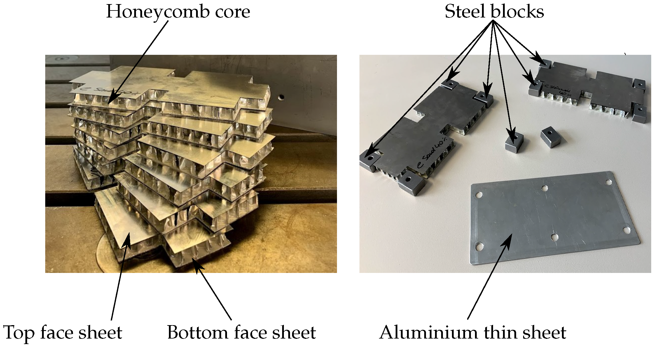
The HCDP consists of two thin face sheets, top and bottom face sheets, respectively. These face sheets are attached to a lightweight honeycomb core through the bonding process, see
Figure 2. The HCDP face sheets and cores are made up of Aluminium to keep the additional mass as low as possible. The geometrical parameters of the honeycomb core profiles are discussed in the previous study [
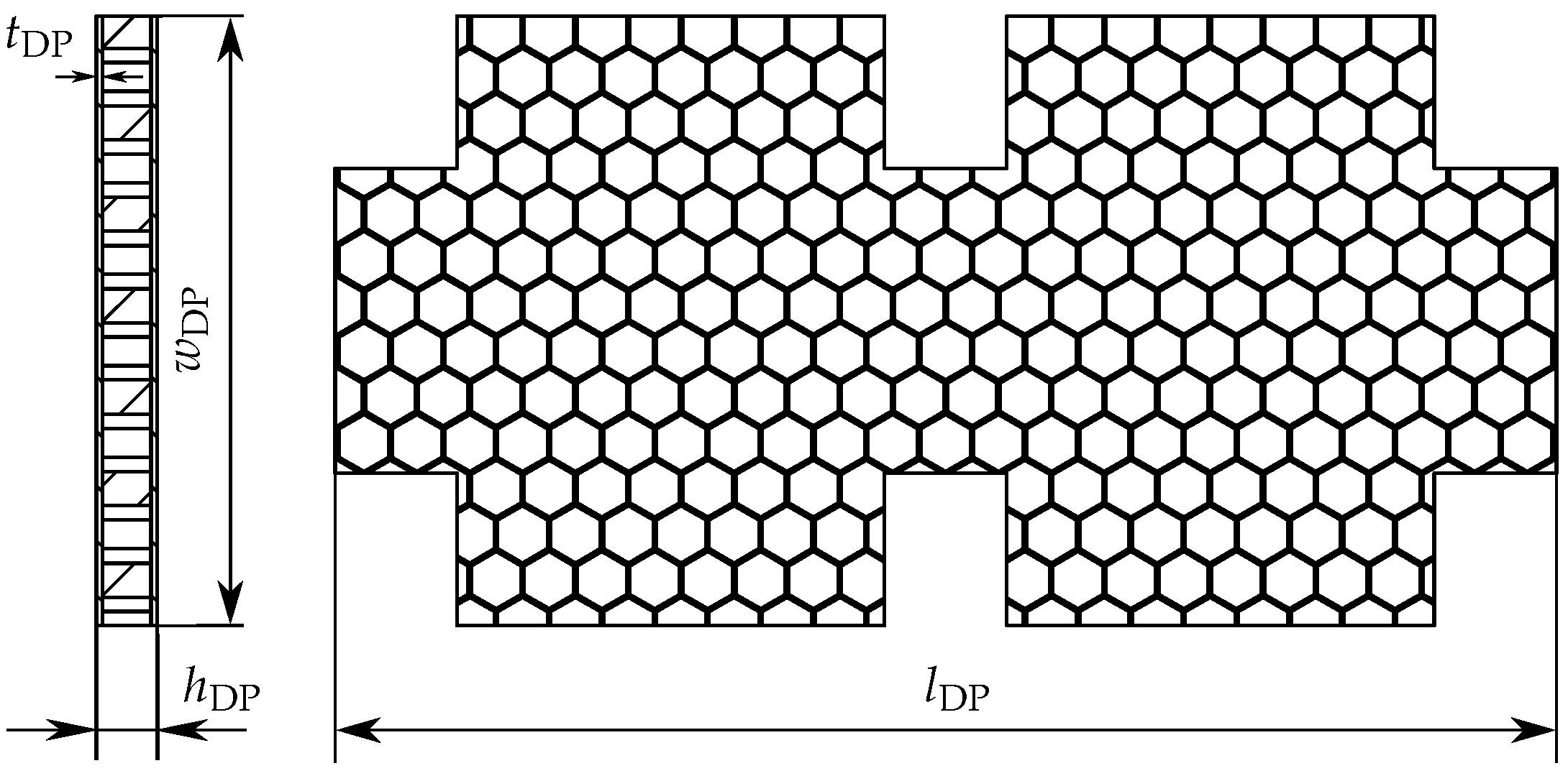
38]. Altogether, seven HCDPs with the same length, width, and core height are manufactured at the IFAM-Dresden. The geometrical properties of HCDP are given in
Figure 3. The thickness of the top face sheet, bottom face sheet, and wall thickness of honeycomb cells are equal. The WTS test specimen without HCDP is considered as the reference test specimen and the obtained results are compared to the WTS test specimen with HCDP attached. For assembling the HCDP at different positions of the WTS test specimen, six rectangular shape cuts are made in the HCDP, which are used to place small steel blocks of thickness
. Afterwards, with the help of an aluminium thin sheet and screws, the HCDP is attached to the stator ring walls. This assembling technique of HDCP to WTS stator is useful for avoiding plastic deformation in the cores during the fastening process. The idea behind using screw joints is that the HCDP can be assembled and disassembled without any complexity. Additionally, the WTS test specimen parts, i.e., stator arm and stator ring along with HCDP can be reused for each experiment. Furthermore, mechanical fastening is a standard joining process, which is also cost-effective and reliable. Adopting this joining technique can reduce the manufacturing cost significantly.
To study the efficiency of the HCDP on the vibration response of the WTS test specimen, four different materials, namely: sand, stone powder, rubber powder, and tungsten powder are chosen. In addition, the influence of an empty HCDP on the vibration response of the WTS test specimen is studied. The idea behind this investigation was to show that the damping is mainly because of granular materials and not merely the design modification effect. The grain size of the chosen granular material particles is distributed non-uniformly. The distribution of particle size and their corresponding average particle size is analyzed by our project partner IFAM-Dresden. The selection of materials for this study was chosen based on their availability in the market and costs. Furthermore, the environmental friendly character of the materials and their recycling properties were also taken into consideration. Along with the influence of materials on vibration attenuation of WTS test specimen, the effect of filling ratios (FR) is also studied. For this purpose, two different filling ratios, namely: FR1 and FR2 are chosen, where FR2 = 0.5 FR1. It should be noted that no HCDP was filled with a
FR as it has been shown in the previous study that it is not effective for vibration attenuation [
17]. In this contribution, the filling ratio is defined as the ratio between the amount of particles filled and the total volume of the cavity. The FR for each HCDP, filling material mass, and the total mass of the HCDP are stated in
Table 2. The distribution of the granular materials in each honeycomb cell is uniform. The granular particles inside each cell are filled in such a way that they do not experience any compression and move freely inside the cavity. Hence, it is crucial not to fill the cavity with a
FR. Because this will restrict the movement of particles, which will then act as a rigid body and not as a particle damper. Therefore, this criterion is necessary to make particle damper more effective as this will increase the probability of collisions of the particles with each other, as well as with the HCDP walls. Furthermore, the influence of single-unit (SU) and multi-unit (MU) HCDP on vibration reduction are studied and compared with each other. MU particle dampers are obtained by assembling the SU particle dampers together.
4. Experimental Setup
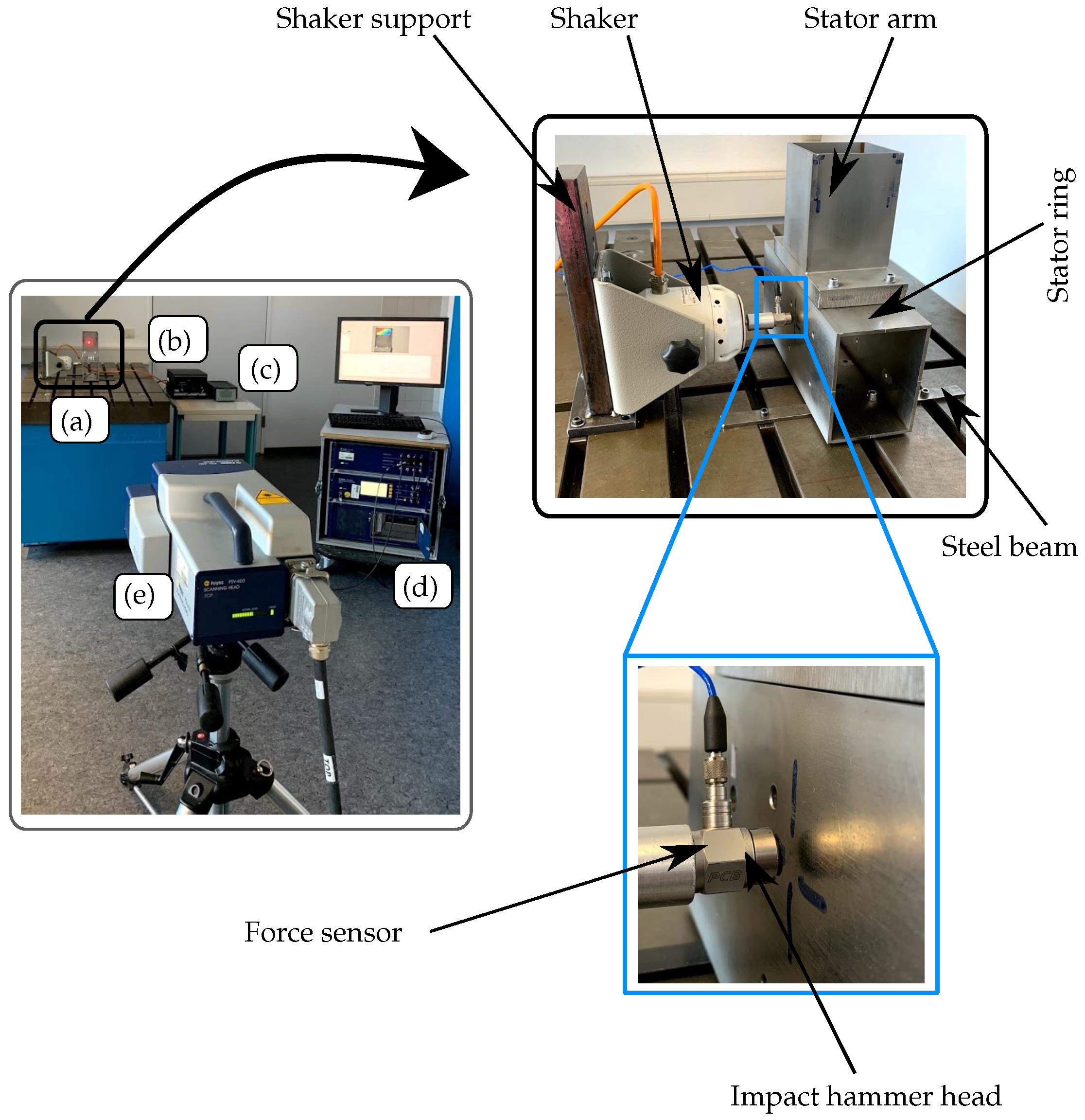
The surface velocity of the WTS test specimen is measured by using a laser scanning vibrometer (LSV) of model PSV-400 from Polytec. The LSV works on the Doppler effect principle and is a contactless optical measuring technique. LSV allows the out-of-plane, as well as the in-plane measurement of surface velocity. It is always the vector of velocity, which is measured in the direction of the laser beam. The experimental setup is shown in
Figure 4. As mentioned previously, in this contribution the efficiency of particle damping technology is investigated by assembling the partially filled HCDP at different locations of the WTS test specimen. To perform this process, assembling and reassembling of each component of the test specimen is required after each set of experiments. This procedure is time-consuming and can also cause several number of uncertainties that can be problematic for reproducing the experimental results. To overcome this problem, i.e., to secure comparable results in all measurements, a clamped boundary condition is considered here that also resembles the real-world scenario. To realize the clamped boundary condition, two identical beam-like structures of steel are constructed and attached to the bottom surface of the stator ring with four bolts of similar dimensions. Afterwards, with the help of four identical bolts and sliding blocks the stator ring with an attached beam-like structure is fixed on the measuring table. The stator arm of the test specimen is assembled on the top of the stator ring by using four identical bolts, nuts, and washer arrangement. For the entire experiment, the stator ring is kept fixed and only the stator arm is assembled and disassembled if required. In previous studies [
18] and also in the current investigation, it has been observed that the structure vibration behavior is also dependent on the bolt tightening procedure. Therefore, it is necessary to maintain the same preload on all bolts for each configuration. Hence, the bolt tightening procedure is carried out with the help of a torque wrench. For assembling the stator arm 6 Nm torque is applied on each bolt. The location of the excitation point is chosen on the outer side of the stator ring and kept fixed for all the experiments to obtain a comparable frequency spectrum. This location was chosen to approximate the real-world scenario and also to obtain as many as possible eigenmodes below 355 Hz. To excite the test specimens an electrodynamic shaker from TIRA has been used. A certain distance is required to be maintained between the impulse hammer head in the test specimen to avoid the double stroke near the excitation point. To fulfill this requirement, a distance of approximately 2 mm is kept fixed between the stator ring and impulse hammer head. To avoid unintended secondary vibration path from shaker to the WTS test specimen the shaker is mounted on an iron frame throughout the experiment. To keep the excitation point identical for each experimental setup, the stator ring is kept fixed for the entire duration of the experiment. A force sensor of model 208C02 from PCB Piezotronics is mounted between the shaker and the impulse hammer head. The force sensor is used for recording the applied load to the structure. An amplifier (Type 2693) from Bruel Kjær and a power amplifier (Type 50,009) from TIRA have been used for the force sensor and the shaker, respectively. To measure the out-of-plane surface velocity of the WTS test specimen, the LSV scan head is positioned horizontally to the test specimen. A linear shaped fine grid consisting of 171 scan points is defined on the top of the stator arm, see
Figure 5. The choice of number of grid points is based on the measurement accuracy and on the time duration of measurement. The number of scan points and the measurement area is kept unchanged for each set of experiment, see
Figure 5. Furthermore, to find a correlation between several parameters to carry out all the experiments a parameter study on the reference WTS test specimen has been performed and their values can be seen in
Table 3. Additionally, to prevent spectral leakage in the measured signals, the Hann-window function is adopted for the entire experiment.
The experiment is first carried out on the reference specimen, i.e., WTS test specimen without the HCDP (see
Figure 6a) to examine the reproducibility of the experimental results. It has been found that reassembling the stator arm of the reference specimen twice while keeping the stator ring fixed, shows a good agreement between the system response, see
Figure A1 in
Appendix A. Furthermore, to control the stability of the reproducibility of the experimental setup, an empty HCDP is mounted between the stator ring and stator arm. To assemble the HCDP, four identical steel blocks along with bolts, nuts, and the washer has been used. The obtained results confirm the robustness of the experimental setup in term of reproducing the system response after reassembling process except for a marginal shift in frequency around 350 Hz, see
Figure A2 in
Appendix A. The same amount of frequency shift around 350 Hz has been also observed for the reference test specimen, see
Figure A1 in
Appendix A. However, this higher frequency shift will not affect the present study, as the peak values are the major parameter for studying the effect of particle damper on vibration attenuation.
Figure 6 shows all the possible configuration of HCDP on the WTS test specimen that has been investigated in this contribution. The partially filled HCDPs and empty HCDP are investigated at each possible position on the test specimen. The WTS test specimen without HCDP, i.e., reference test specimen is given in
Figure 6a. Firstly, the single-unit (SU) HCDP is mounted between the stator ring and stator arm, and its effect on test specimen vibration attenuation is studied, see
Figure 6b. The best performing partially filled HCDP at this location is combined with its corresponding HCDP with different FR to investigate the multi-unit (MU) HCDP influence on transmission path damping, see
Figure 6c. Afterwards, the SU HCDPs are attached to the outer wall of the stator ring, which is opposite to the excitation point, see
Figure 6d. The material performance ranking obtained through this test is used for constructing a MU HCDP set-up at the same location, see
Figure 6e. Similarly, MU HCDP is assembled to the inner wall of the stator ring to investigate their effect on the WTS test specimen vibration attenuation, see
Figure 6f. Likewise, SU HCDP is attached to the inner wall of the stator ring for vibration attenuation analysis, see
Figure 6g. Based on the results obtained through the above-mentioned HCDP positions on the WTS test specimen, the effect of three different combined configurations of the HCDP, namely: Configuration 1, Configuration 2, and Configuration 3, on transmission path damping are also investigated, see
Figure 6h–j. In Configuration 1, two different locations for the HCDP are chosen. In this configuration, a SU HCDP is mounted between the stator arm and stator ring, which is followed by a MU set-up of HCDP on the outer wall of the stator ring, which is opposite to the excitation point. The setup for Configuration 2 is similar to Configuration 1. The only difference is that instead of MU HCDP, a SU HCDP is mounted on the outer wall of the stator ring. Configuration 3 is a combination of SU and MU HCDP. Likewise in Configuration 1, Configuration 3 also contains a MU HCDP that is mounted on the outer wall of the stator ring. Furthermore, a SU HCDP is mounted on the inner wall of the stator ring (excitation point side) as well as between the stator arm and stator ring.
5. Results and Discussions
The frequency response function (FRF) of the WTS test specimen with and without HCDP is plotted in a narrow frequency band and a one-third octave band. The narrow frequency band spectrum in this study is mainly used to extract the information about the number of resonance frequencies (
Hz,
Hz,
Hz,
Hz,
Hz,
Hz,
Hz) that are occurring below 355 Hz, see
Figure 7. In the present experimental study, one-third octave band is more suitable for comparing vibration attenuation, see
Figure 8. In this contribution, only the one-third octave bands around the most prominent resonance peaks are of special interest. To make these frequency ranges easily recognizable, gray patches in the FRF are plotted. Furthermore, for each HCDP position on the WTS test specimen (see
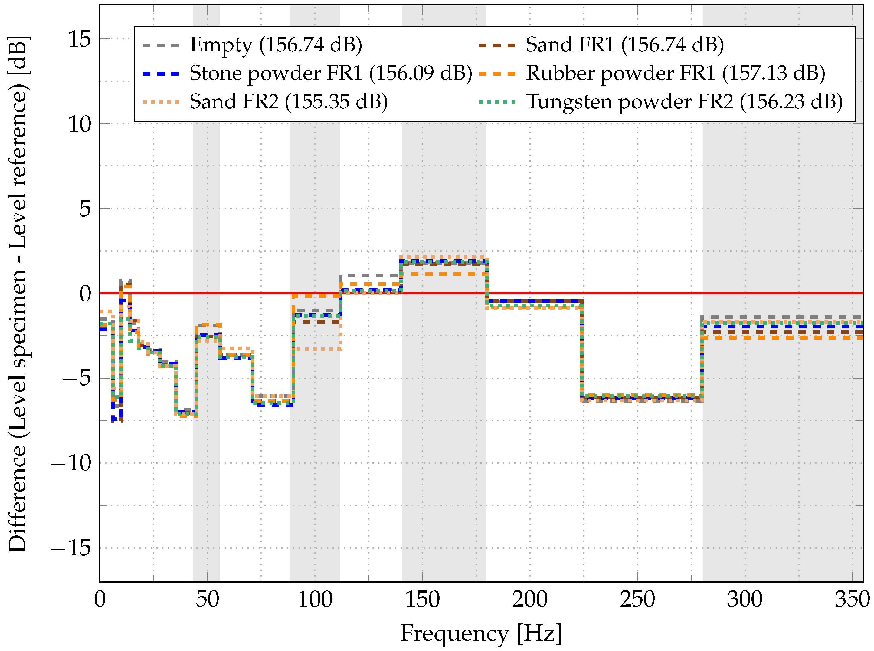
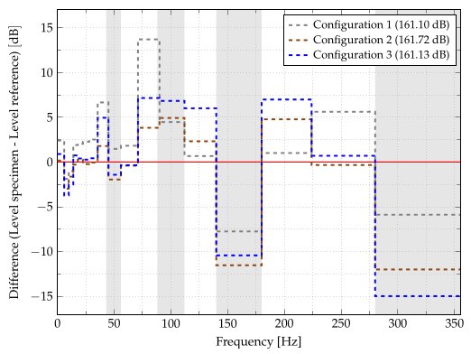
Figure 6) the difference in the vibration amplitude in comparison to the reference specimen around resonance peaks is plotted, see
Figure 9. The gray patches are also used in this plot to identify the one-third octave frequency band around which the highest vibration amplitude is occurring. The horizontal red line in the difference plot (see
Figure 9) represents 0 dB. The region above the red line shows an increase in the vibration amplitude and the region below the red line represent a reduction in the vibration amplitude.
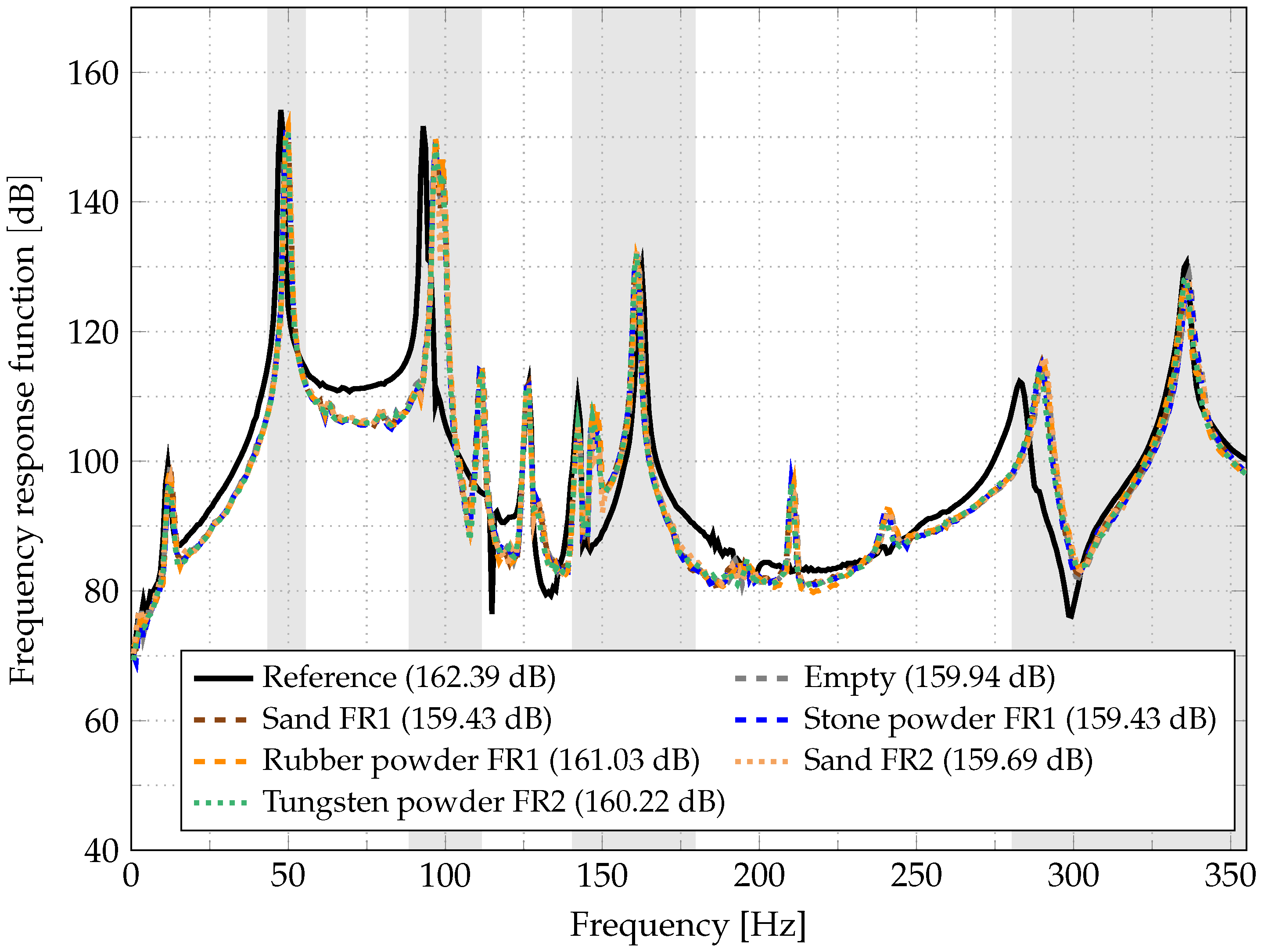
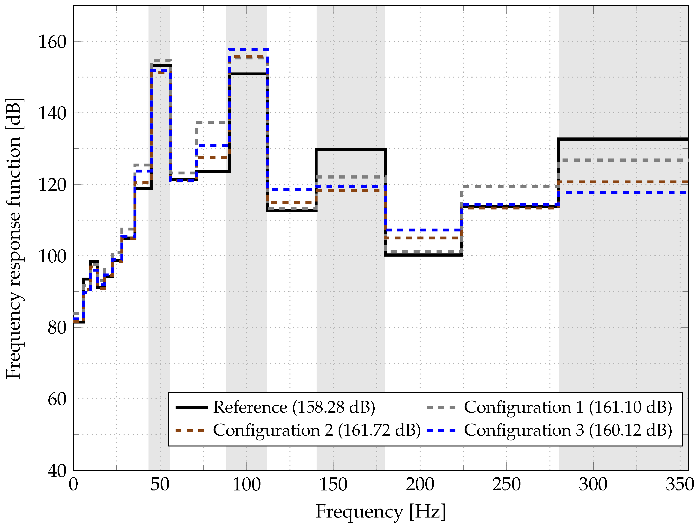
In
Figure 7,
Figure 8 and
Figure 9, FRF and the vibration attenuation obtained by attaching the MU configuration on the outer wall of the generator ring (see
Figure 6e) is plotted. MU HCDP is obtained by joining the SU HCDP together. In this case, SU HCDP filled with stone powder is mounted together with a SU HCDP filled with sand to create MU configuration. Both SU HCDP are having a filling ratio of FR1. The resonance frequency of this system is plotted in the narrow band spectrum, see
Figure 7. In the one-third octave band plot, it is visible that mounting the MU HCDP on the outer wall of the WTS ring reduced the vibration amplitude over the whole frequency range from 45 Hz to 355 Hz except for the central frequency of 125 Hz, where this configuration increases the vibration amplitude by approximately 1 dB, see
Figure 8. As mentioned before, the present damping concept is only analyzed for the most prominent resonance peak, which is marked through gray patches. Therefore, the resonance peak occurring around 125 Hz is not crucial for this damping concept. Furthermore, the sum level (SL) value of the surface velocity (logarithmic measure of the effective surface velocity relative to a reference value) for the MU configuration on the outer wall of the generator ring (
dB) in comparison to the SL value for the reference test specimen (
dB) also confirms the tremendous damping achieved by this MU HCDP setup. This MU setup can reduce the vibration amplitude up to 12 dB (dark blue dotted line), see
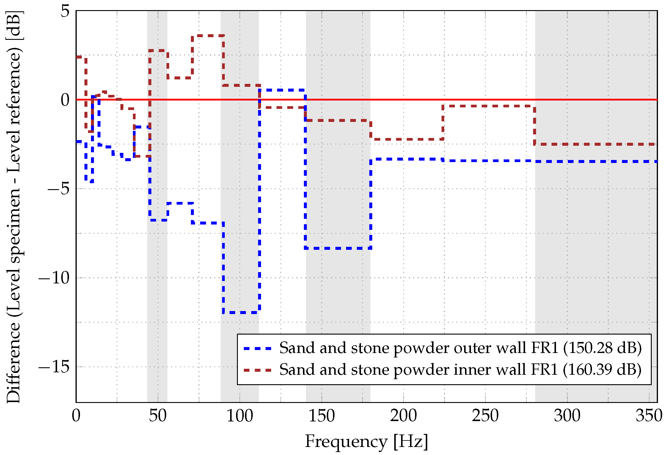
Figure 9. In contrast, the same MU HCDP configuration attached to the inner wall of the WTS ring (see
Figure 6f) shows almost no efficiency in reducing the vibration amplitude (brown dashed line). This phenomenon can also be observed in the higher SL value (
dB) in comparison to the reference specimen SL value (
dB). The above mentioned results show that the position of HCDP on the WTS test specimen is very crucial for reducing the vibration amplitude. Furthermore, this observation also leads to a conclusion that attaching the HCDP on the outside of the WTS wall is not only effective for broadband damping but also favorable for industrial implementation after proper optimization.
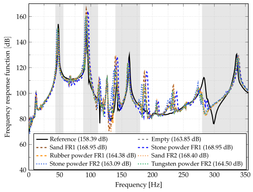
To evaluate the effect of particle damper the SU HCDP is fixed on the outer wall of the WTS ring, which is opposite to the excitation point, see
Figure 6d. The experimental results of this configuration are plotted in
Figure A3,
Figure A4 and
Figure A5. From the narrow band spectrum, it can be noted that the reference test specimen and test specimen with attached SU HCDP have several resonances peaks, see
Figure A3. Near the first resonance peak (
Hz), all SU HCDP can reduce the vibration amplitude significantly. It is observed that for the first natural frequency, the SU HCDP filled with stone powder and sand with a filling ratio of FR1 are most effective for vibration attenuation and reduce the vibration amplitude by
dB and
dB, respectively, see
Figure A5. Furthermore, it has been observed that attaching SU HCDP to the outer wall of the WTS ring also reduce the vibration amplitude near the third and fourth resonance peaks. However, for the resonance near 150 Hz, the vibration amplitude of the WTS test specimen with attached SU HCDP is higher than the reference values of WTS test specimen. Additionally, a slight frequency shift has been also observed that is coming because of HCDP extra mass.
Moreover, attaching the SU HCDP at this location is increasing the vibration amplitude for the resonance peak around 100 Hz. Nevertheless, the overall damping characteristic of stone powder and sand is very similar, which can also be observed in their SL value of surface velocity. An empty HCDP is also attached to the WTS ring to show that the vibration reduction is mainly coming due to the particle damping mechanism and not only because of mass, see
Figure A3,
Figure A4 and
Figure A5. The influence of empty HCDP for each SU HCDP configuration at a different location on the WTS test specimen is investigated because its response on FRF is dependent on mounting position. From the above discussion, it can be concluded that the presented configuration shows a significant reduction in vibration amplitude for the resonance peaks near 50 Hz, 150 Hz, and 355 Hz. It has been also observed that stone powder and sand show the maximum vibration reduction near first resonance peaks in comparison to other granular materials. Conclusively, attaching the SU HCDP to the outer wall of the generator ring is not effective for broadband damping, which can also be observed in the SL values of SU HCDP in comparison to the reference specimen SL value.
The experimental results for the HCDP position between stator arm and stator ring are plotted in
Figure A6,
Figure A7 and
Figure A8. Resonance frequencies of the WTS test specimen can be seen in
Figure A6. Placing the SU HCDP between the WTS arm and ring can reduce the vibration amplitude significantly near 150 Hz. A very similar effect has been also observed for the resonance near 355 Hz, see
Figure A7. However, for the first resonance peak near 50 Hz, only SU HCDP filled with tungsten powder (green dotted line) and MU HCDP filled with sand (violet dashed line) are effective for vibration attenuation and reduce the vibration amplitude up to
dB and
dB, respectively, see
Figure A8. MU HCDP set up in this configuration is not very useful in comparison to SU HCDP setup. It has been observed that the empty HCDP (gray dashed line) either increases the vibration amplitude or shows no damping effect, except for the resonance peak near 150 Hz, where the damping value due to empty HCDP is similar to the damping value obtained by attaching a SU HCDP filled with rubber powder with filling ratio FR1 (orange dashed line). Nevertheless, attaching empty HCDP between the stator arm and ring increase the overall vibration amplitude of the primary structure, which can be observed in the SL value of the surface velocity, see
Figure A6. Although, mounting the SU or MU HCDP between the stator arm and ring can reduce the vibration amplitude. However, for the real-world application, this configuration can be very critical as it can make the complete WTS structure unstable. Currently, at an industrial scale welding process is used to join the WTS arm and ring together. Attaching the partially filled HCDP at this particular location in the WTS will require an extensive analysis of the fastening joining process. Hence, implementation of the above mentioned configuration at an industrial scale is tedious for the manufacturing, production, and assembling process.
In the next step, SU HCDP is mounted to the inner wall of the WTS ring (on the excitation point side), see
Figure 6g. The results of this configuration can be seen in
Figure A9,
Figure A10 and
Figure A11. As expected, this configuration also exhibits a similar number of resonance frequencies as discussed for others locations of HCDP. It has been observed here that mounting partially filled HCDP at this location can reduce the vibration amplitude significantly for the resonance peaks near 50 Hz, 100 Hz, and 355 Hz, see
Figure A11. However, vibration attenuation due to granular materials is not observable because the reduction in vibration amplitude due to the empty HCDP is very similar to the partially filled HCDP. This observation can also be justified by comparing the SL values of surface velocity. Furthermore, the filling ratio also shows almost no influence on damping. Hence, it can be concluded that mounting HCDP at this location may increase the bending stiffness of the primary structure, which is mainly responsible for the vibration attenuation, i.e., reduction in vibration amplitude, which can be seen in
Figure A9,
Figure A10 and
Figure A11, is because of higher bending stiffness and not due to particle damping mechanism. This observation is reasonable as the width contributes linearly to both the resulting stiffness and mass.
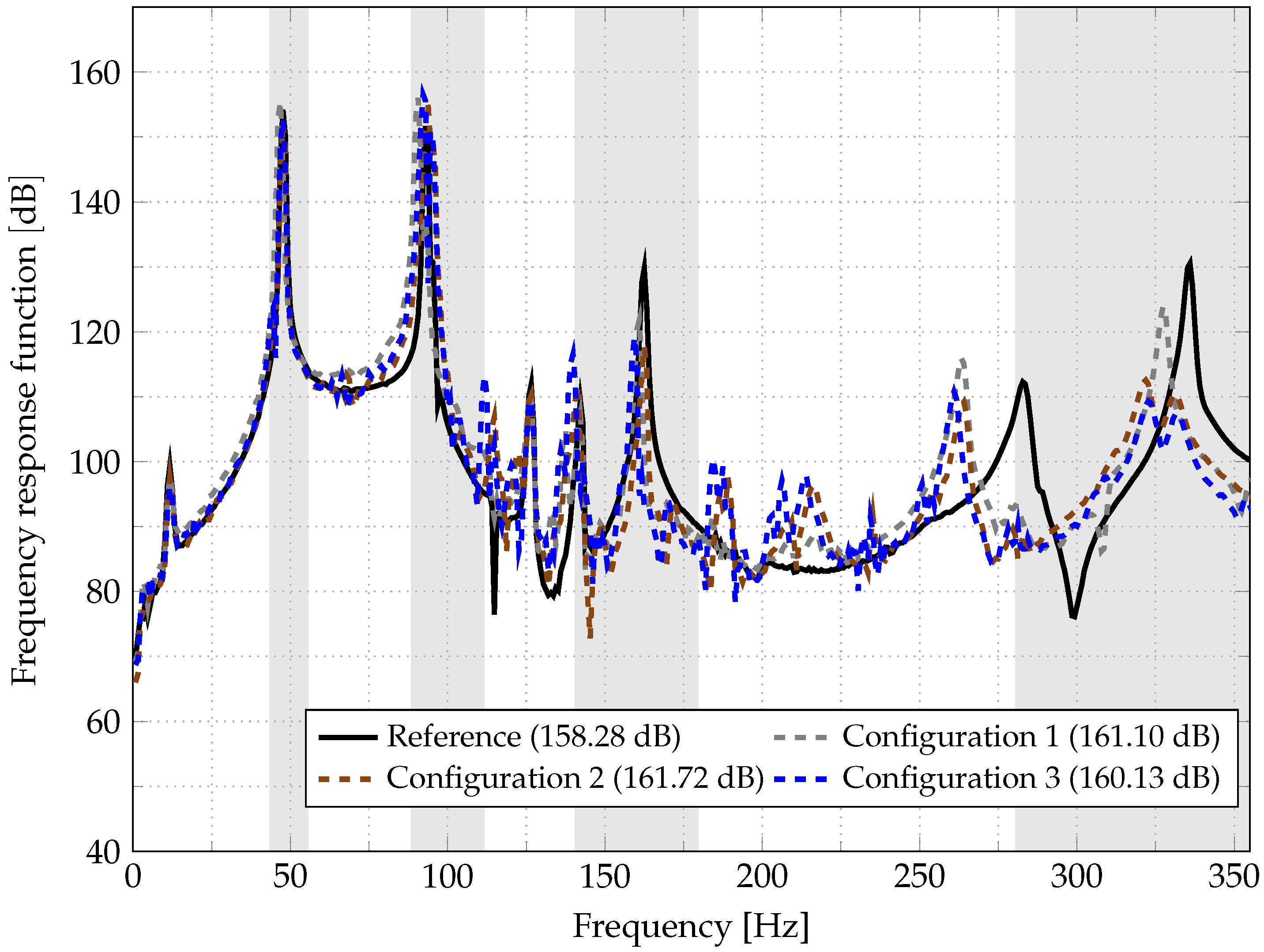
In a follow up, SU and MU HCDP are mounted at different locations to WTS test specimen simultaneously, namely: configuration 1, configuration 2, and configuration 3. In configuration 1, a MU HCDP filled with stone powder and sand is mounted to the outer wall of the WTS ring because as discussed above, this combination of HCDP yields maximum vibration attenuation of the WTS test specimen. Along with this, a SU HCDP filled with tungsten powder is attached between the stator arm and ring because at this location tungsten powder shows broadband damping, see
Figure 6h. This configuration reduces the vibration amplitude by
dB,
dB, and
dB at resonance peaks near 50 Hz, 150 Hz, and 355 Hz, respectively, see
Figure A14. The setup for configuration 2 is very similar to configuration 1, in which only SU HCDP is attached to the WTS test specimen, see
Figure 6i. This configuration is only effective for resonance peaks near 150 Hz and 355 Hz, see
Figure A14. Configuration 3 is an extension of configuration 1, in which an empty HCDP is attached to the inner wall of the WTS ring at the excitation point side. The decision for attaching an empty HCDP at this position was taken because at this location damping is coming due to higher bending stiffness of the primary structure and not because of granular materials. The damping characteristic of this configuration is very similar to the damping characteristic of configuration 1. The SL values of all three configurations mentioned above are almost similar and are larger than the reference specimen SL values (
dB).
From the above discussion, it can be concluded that the MU HCDP when attached to the outer wall of the WTS ring (opposite to the excitation point) is the most effective location of the HCDP on the WTS test specimen for reducing the vibration amplitude in comparison to the other setup. Furthermore, it has been also observed that the position of the HCDP on the WTS test specimen plays a very crucial role for vibration attenuation.
6. Conclusions
The paper aims to investigate the potential of particle damping techniques in reducing the vibration and sound emission of a wind turbine generator. For this purpose, honeycomb damping plate concept has been developed, which is partially filled with granular materials. The wind turbine stator test specimen without honeycomb damping plate is considered as the reference specimen. The honeycomb damping plates are mounted at different locations of the wind turbine stator test specimen to reduce the vibration amplitude. Altogether, there are four different possible locations to attach the honeycomb damping plate enclosing granular materials, namely: between the wind turbine stator arm and ring, to the outer wall and inner wall of the wind turbine stator ring that is opposite to the excitation point, and to the excitation point side. Apart from this multiple honeycomb damping plates are attached at a different location to the wind turbine stator test specimen simultaneously. In the first place, single-unit honeycomb damping plate is mounted at each location to find out the best two granular materials, which are then used to construct a multi-unit honeycomb damping plate setup. The effect of honeycomb damping plate location, granular material, and the filling ratio has been investigated in this paper. However, a broadband damping up to 12 dB is achieved exclusively by mounting a multi-unit honeycomb damping plate to the outer wall of the wind turbine stator ring (opposite to the excitation point). At this particular location, single-unit honeycomb damping plate filled with stone powder and sand were the best two granular materials for vibration attenuation at a lower frequency. Hence, multi-unit honeycomb damping plate is constructed by joining this two honeycomb damping pate with a filling ratio of FR1. The approximately additional mass due to granular material, honeycomb damping plate material, fastening joining system, thin aluminium sheet, and steel blocks is a matter of concern. Moreover, the position of the honeycomb damping plate on the wind turbine stator plays a crucial part in vibration attenuation. Furthermore, this concept can be tedious in terms of the manufacturing and production process. Apart from this, comprehensive strength analysis and a bonding joining process analysis for honeycomb damping plate are required. The current experimental investigation provides essential input for implementing the honeycomb damping plate concept in reducing the vibration amplitude from a wind turbine generator. However, implementing the above mentioned concept at an industrial scale requires further investigation, like design optimization and strength and fatigue analysis. Therefore, in the next step of this project a “single cavity concept” is developed and is currently under investigation. Along with this more filling materials and their distribution will be evaluated.


