1. Introduction
Compliance-based camber morphing wings have the potential to improve aerodynamic performance in both fixed and rotary wings. This aerodynamic improvement is due to their ability to actively vary airfoil camber in a smooth and continuous way so that the airfoil geometry can adapt to the continuous changes in operating conditions (e.g., changes in altitude, speed, weight, weather conditions). Unsurprisingly, camber morphing has been a popular research topic in the past few decades [
1,
2] due to its potential to significantly contribute to reducing the environmental impact of the aviation sector by reducing fuel consumption [
3,
4]. Advancements in smart materials and lightweight structures, which have led to lighter and less complex morphing mechanisms. For example, developments in piezoelectric materials [
5,
6] and Shape-Memory Alloys (SMA) [
7,
8] have focused on exploring alternative actuation mechanisms, whereas the further understanding of composite laminates has led to exploiting structural instabilities for shape changing [
9,
10,
11]. Furthermore, some concepts achieved variable camber by embedding actuators within the wing skin [
5,
12], whereas others focused on active actuation of the internal load-bearing structural members [
8,
13,
14,
15].
Despite the actuation mechanisms, a common aspect among the majority of these morphing concepts is that the change in shape does not occur across the entire aerofoil section but is mainly localised on the trailing edge, where the aerodynamic loads are relatively low. However, there are concepts that have developed morphing leading-edge devices, such as a compliant ’droop-nose’ morphing leading edge using superelastic materials [
16], whereas others have combined both leading and trailing-edge morphing devices [
17]. Similarly, Werter et al. [
18] proposed leading and trailing-edge morphing devices that combined skin warping and bending to induce shape change. This research effort focused on developing a morphing mechanism that could be retrofitted to an existing aircraft using as many off-the-shelf components as possible.
In general, it can be said that compliance-based camber morphing devices can achieve continuous and smooth shape adaptation as they are designed to be compliant along the direction where shape change occurs. This compliance is normally achieved by a combination of both geometric design (i.e., carefully considering where to allocate geometric stiffness) and an adequate material selection [
6]. Thus, these devices normally have multiple structural elements and material types that must be combined in a ‘seamless’ way. Therefore, one main challenge in camber morphing research is how to manufacture these multi-element and multi-material devices so that the following goals can be achieved:
(a) the inclusion of aerospace-grade materials,
(b) the reduction in part count and manufacturing steps and
(c) the ability to easily remove or replace components for maintenance purposes.
One camber morphing concept that has shown promising aerodynamic results and has made good progress in terms of manufacturability is the Fish Bone Active Camber (FishBAC) device. The FishBAC is a morphing device that achieves its compliance through both geometry and material choice. It consists of a central bending spine made from a thin composite plate placed at the trailing edge of the aerofoil. Onto this flexible spine are placed a series of spanwise stringers that support the aerodynamic skin and add additional spanwise rigidity without significantly adding stiffness in the direction of shape change. An elastomeric outer skin membrane is stretched over the stringers, and a series of tendon spooling actuation mechanisms are placed along the span to drive the shape change. Initially introduced by Woods and Friswell in 2013 [
19], the FishBAC has significantly evolved in terms of the manufacturing and material selection process since its introduction.
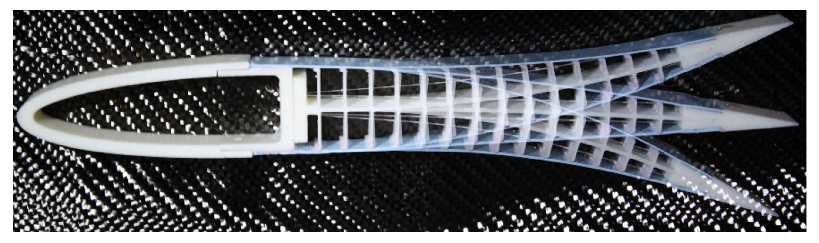
The first generation of FishBAC devices was mainly manufactured by 3D printing (
Figure 1). The stringers and spine were printed together as a single internal ‘skeleton’. Furthermore, a silicone elastomer skin was pre-stretched and bonded to this skeleton, whereas the pulley mechanisms were manufactured separately and later installed. Kevlar tendons were used to transmit the actuation loads from the servos to the trailing edge of the morphing device. These were anchored to the pulleys on one end and hand-stitched to the trailing edge on the other end [
20,
21]. Although the 3D printing process is ideal in terms of reducing part count, as the stringers do not need to be later attached to the spine, 3D-printed ABS plastic is not an aerospace-grade material, and its use is far from ideal in terms of its stiffness and strength. However, these prototypes were still key for investigating the aerodynamic benefits of the FishBAC via wind tunnel testing [
22].
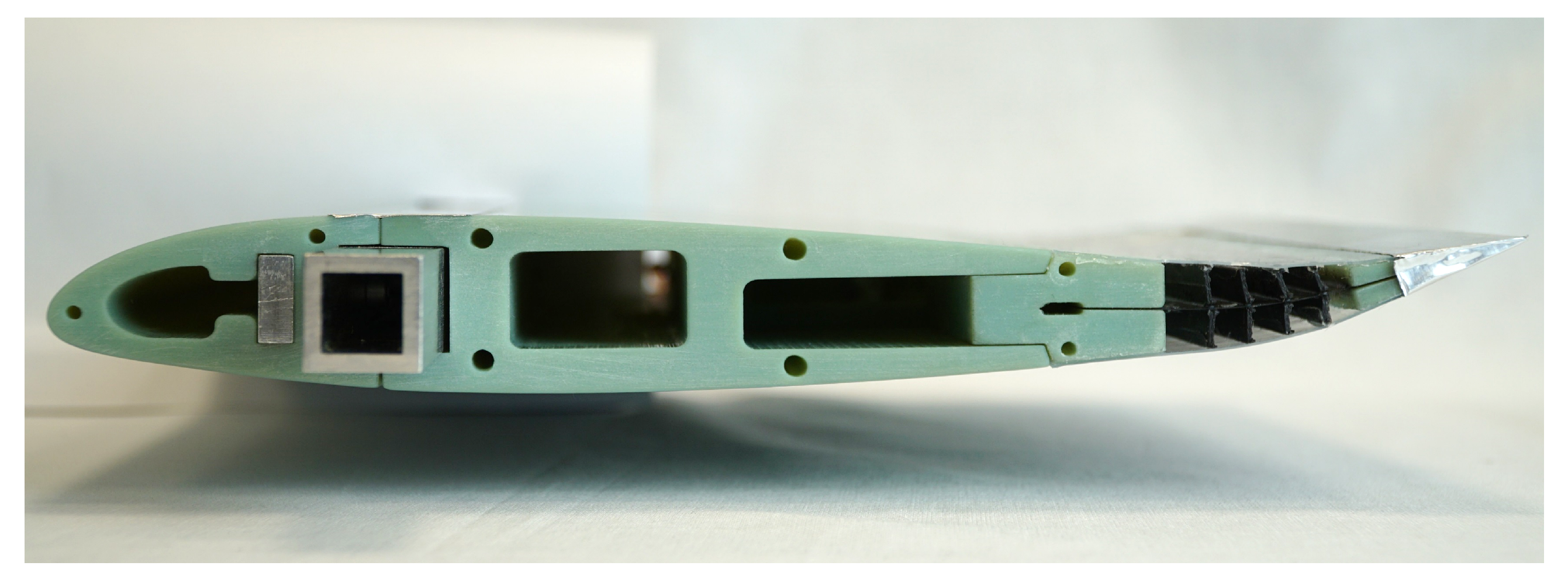
The second generation of FishBAC devices was designed and manufactured around incorporating carbon fibre-reinforced composite to the spine (
Figure 2), which presents significantly improved material properties when compared to 3D-printed plastics, and also allows for stiffness tailoring by exploiting variations in the fibre angle [
23]. This generation of FishBAC devices was useful to further study the aerodynamic behaviour of the FishBAC by conducting comprehensive wind tunnel experiments that showed the clear aerodynamic benefits that this morphing device has when compared to a hinged trailing-edge flap of similar dimensions [
24]. However, one clear disadvantage of using a carbon fibre laminate for the spine is that the stringers have to be bonded to the spine, which increases the time and complexity of the manufacturing process, as well as the part count. Additionally, the first and second generation of FishBAC devices required the tendons to be hand-stitched and sealed with adhesive, whereas the elastomeric skin had to be manually bonded. Thus, neither the tendons nor the stringers could be replaced without removing the skins, and the tendons’ tension themselves could not be adjusted as they were bonded to the device.
The aim of this work is to address these limitations in the first and second-generation FishBACs by designing, manufacturing and wind tunnel testing a FishBAC wind tunnel wing model where: (a) each structural member can be removed and replaced, (b) the tendon tension can be adjusted and (c) the skins and stringers can be attached without using any adhesive. This is achieved by combining traditional manufacturing techniques, such as machining for the actuation mechanism and composite hand layup for the spine, with a novel morphing skin design that is manufactured by 3D printing the skins and the stringers together using two different materials that are fused during the printing process. This paper presents the successful design, manufacture and wind tunnel testing of the first third-generation FishBAC device.
2. Design Requirements
The main objective of this design and manufacturing process is to build a wind tunnel wing model for a quasi-2D wind tunnel test (i.e., a wing that spans the test section). In this application, the wing has to span a 1-m test section; therefore, it was designed to have a wingspan of
995 mm, so that a 2.5 mm gap exists between the wing-tips and the tunnel walls to avoid interference. A NACA 23012 airfoil modified with a trailing-edge tab with a 270 mm chord length was selected. This airfoil matches that of a Bo-105 helicopter, which is the baseline rotor system of the EU Horizon 2020’s Shape Adaptive Blades for Rotorcraft Efficiency (SABRE) project [
25], for which this work was carried out. The FishBAC device is located in the rear 25% of the airfoil section (i.e., starting at the location
). Therefore, the front 75% of the airfoil section is rigid and should be robust enough to sustain a maximum testing speed of 50 m s
−1 (with a factor of safety of 1.5).
In terms of stiffness and actuation requirements, the composite-spine second generation FishBAC device was used as a baseline [
26]. However, one limitation of this design was the significant amount of spanwise elastic washout observed when the device was deflected, which was caused by a lack of spanwise stiffness combined with the presence of only two actuation points spread out toward each wing-tip. To address this limitation, further work was performed to select the spine stacking sequence, and one additional actuation point was added at the wing’s midspan. Another important limitation of the previous wing design was the inability to adjust the tension applied to each tendon once it was fixed to the morphing device, which was addressed in this design by creating an adjustable tensioning mechanism. A detailed explanation of how these limitations were addressed are presented in the following sections of this paper.
3. FishBAC and Wing Design and Manufacture
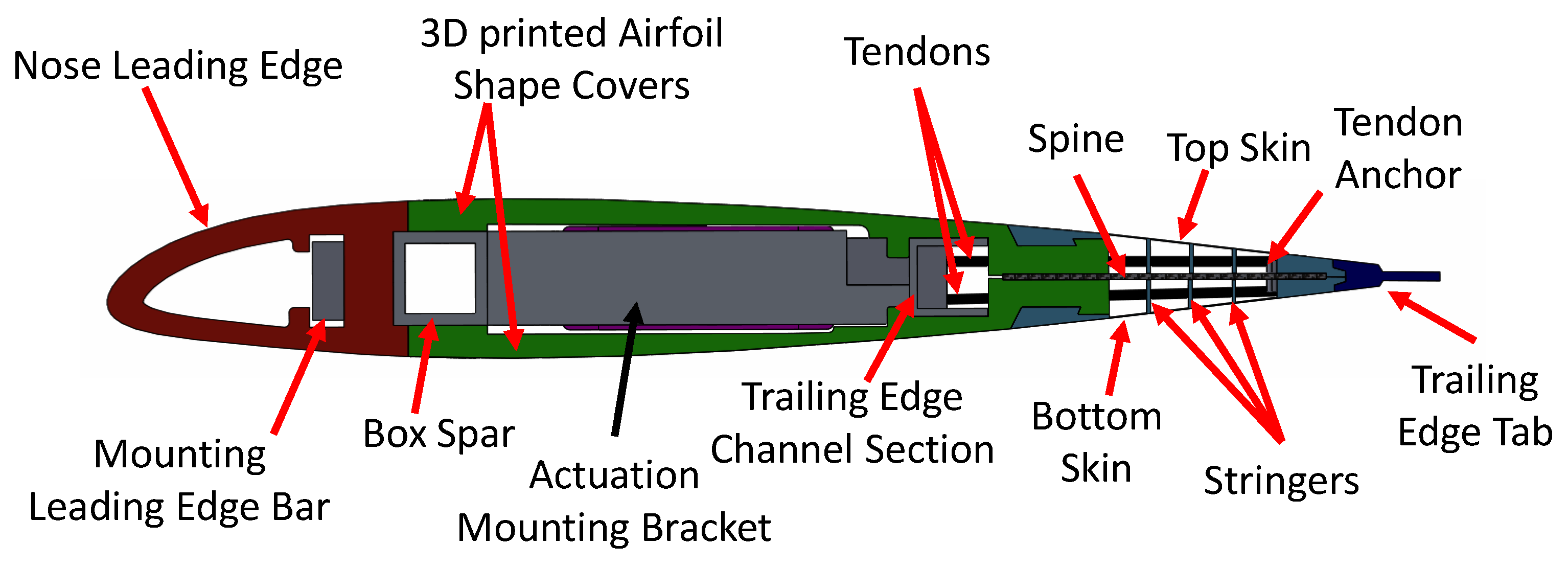
This section will discuss how the various components of the FishBAC morphing trailing edge and the rest of the wind tunnel model were designed and built. The design philosophy followed for this morphing wing was to create a fully-modular wing, where each one of the components can be removed and replaced without having to scrap any other components. In terms of the FishBAC itself, which accounts for the rearmost 25% of the chord, five different components can be observed in
Figure 3: a carbon fibre-reinforced composite spine, a series of spanwise stingers, two skin surfaces, a tendon anchor made of two aluminium alloy parts and a trailing-edge tab. Details on how each one of these components was designed will be provided in the following subsections.
3.1. Spine Sizing and Manufacture
The spine sizing was performed by using an already existing Finite Element Method (FEM) model of a composite FishBAC device [
27], which included the presence of both skin and stringers. Since the spine is made of carbon fibre-reinforced polymer, the spine stiffness is determined by both its thickness and its stacking sequence (i.e., fibre angle orientation). It is worth remembering that the FishBAC is structurally designed to have a lower stiffness along the chordwise bending direction than along the span so that the energy required for shape change is reduced. However, the wing is not infinitely stiff along the span, and so there will always be some amount of elastic washout between actuation stations. For a full three-dimensional wing design, the FishBAC geometry and material properties can be tailored to provide the correct balance between stiffnesses. In the case of this wind tunnel test, the focus was on trying to have fairly consistent deflections along the span. Since the wing will be actuated at three discrete points along the span, it is crucial that the spanwise stiffness is high enough so that the morphed camber shapes can be maintained along the span. As mentioned in the introduction, the second generation FishBAC wind tunnel prototype showed significant elastic washout [
23], which must be addressed in this new design.
Since this wind tunnel wing model was designed for a quasi-2D wind tunnel test, the achieved deflections should be as uniform as possible (along the span). Therefore, only balanced and symmetric laminates were considered. The two main variables to consider are laminate thickness and stacking sequence. Because carbon fibre prepreg was used in this case, the laminate thickness is determined by the number of plies.
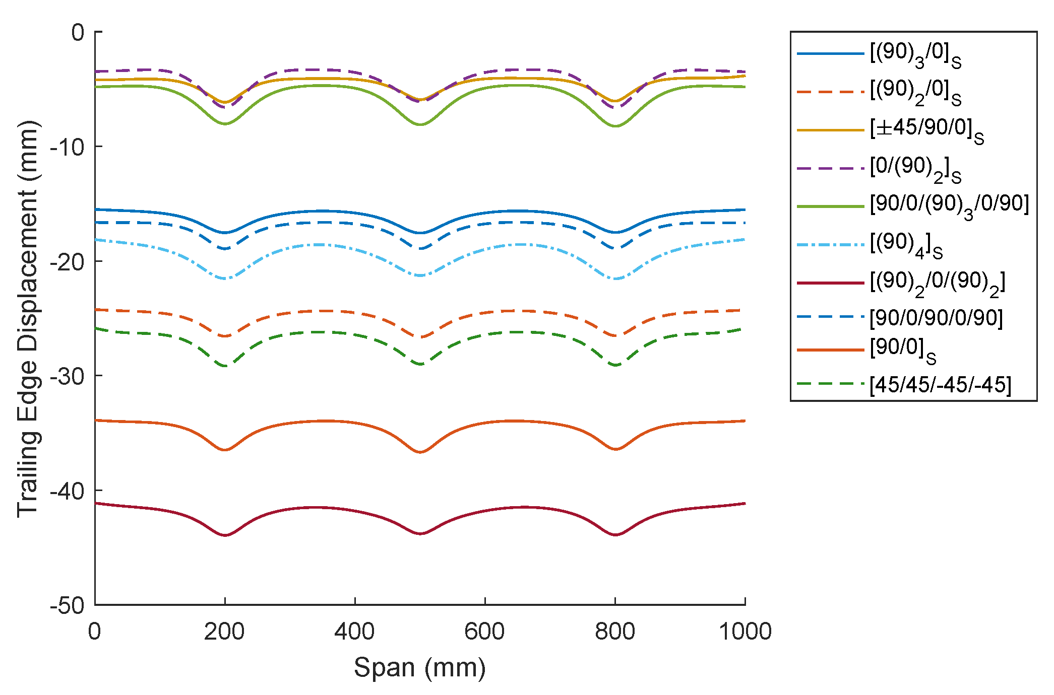
Figure 4 includes the results for all the stacking sequences that were considered in the FEM analysis. Since the objective is to select a stacking sequence that both minimises the variations in the transverse deflection along the span and allows achieving large transverse deflections, the selection is performed in terms of the ratio between the minimum and maximum transverse deflections (along the span) and the maximum achievable deflection. It is observed in
Table 1 that the best performing laminate according to these objectives is
, as it presents the largest deflections under the selected actuation loads and has the lowest variation in transverse displacement along the span. However, it is important to note that this “theoretical”’ maximum displacement is likely an overestimation, as no losses in the actuation mechanism are being considered (e.g., due to mechanical friction in the pulley-tendon system or actuator efficiency factors).
The composite spine was manufactured using Hexcel’s 8552/IM7 carbon fibre-reinforced prepreg. The layup was performed by hand on a steel tooling plate and then cured under 8552/IM7’s standard vacuum bag cured cycle—with a cure temperature of 180 °C, autoclave pressure of 7 bar and −1 bar vacuum pressure inside the vacuum bag. The cure cycle was controlled using three thermocouples that were placed on the vacuum bag at three different locations. Along with the composite spine, three additional plates were manufactured to perform material characterisation and were cured under the same vacuum bag and cure cycle. Therefore, the results obtained via these material characterisation experiments should correspond to the material properties of this FishBAC’s composite spine. Once the spine was cured, it was milled to size, and the holes and features were machined using carbide-coated crown point drill bits.
3.2. Actuation Mechanism & Tendon Anchoring
The actuation mechanism of the latest FishBAC generation has been envisaged to improve access for assembly, replacement of the components and adjustment of the tendons, as well as to provide higher structural performances required to operate under high actuation loads. To achieve this, the main individual parts have been designed with all the features required to mount and operate the servo-tendons system allowing for quick disassembling from the main structure and relatively easy components replacement or adjustment.
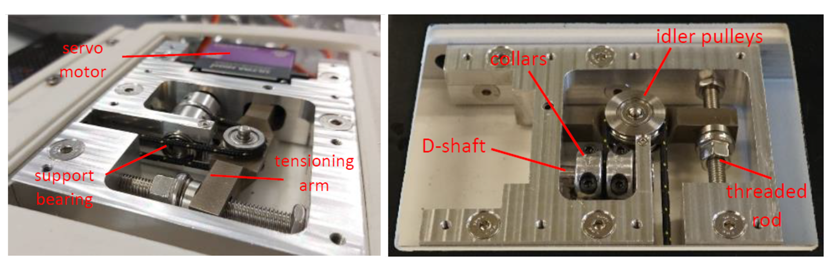
The actuation is provided by a high torque brushless digital servo motor (
Figure 5), with a nominal stall torque of 45.5 kg cm, that meets both the actuation torque requirements and geometric constraints imposed by the Bo-105 blade cross-section. This servo has an operating travel range of ±45°, and an operating speed at no load of 0.1 s/60° (at a maximum supply voltage of 8.4 V). The torque is transmitted to the FishBAC’s trailing edge through a tendon on either side of the spine, both wound around and connected to a 6.35 mm steel shaft that is then attached to the servo spline through an adaptor with the set screw. This setup is defined as the “spooling pulley”. A 2 mm-diameter high-performance polyester-coated Vectran rope was used for the tendon. This material choice gives the rope excellent stiffness and strength, along with very low cold creep properties (under tension) and reduced tendon-pulley friction.
The tendons are anchored to the D-shaft using aluminium collars with clamp screws. The collars clamp the wound-up tendons to the shaft on either side of the loading path, leaving enough clearance between them to allow the winding and unwinding of both tendons. Finally, the tendons connect to the trailing edge through a tendon anchor, a two-piece aluminium component screwed together to clamp to the spine, as seen in
Figure 6.
A monolithic actuation frame, machined from 6082-T6 aluminium alloy billet, is mounted in between the front and rear spars. This removable bracket hosts the actuation mechanism (mounts the servo, supports the shaft and tension the tensioning arm) and also connects the two spars, ensuring full load transfer between them. Tendon tensioning is achieved via a tensioning arm, which pivots off of the actuation frame to support a pulley around which the tendon wraps. The arm can be drawn towards the leading edge via a nut on a threaded rod, which increases the path length the tendon must travel, thereby creating variable tendon tension. The initial resting position of the FishBAC can also be adjusted by introducing differential tensioning of the upper and lower tendons via offsetting the tendons at their clamping points on the spooling pulley.
Figure 6 shows the components of this actuation mechanism.
3.3. Skin and Stringer Design
As briefly mentioned in the introduction, one of the main challenges in manufacturing FishBAC devices is how to attach the stringers to the spine, and then the skins to the stringers. To improve the manufacturing process, a novel technique is proposed: to manufacture the skins and stringer as a single component using a two-phase additive manufacturing process (combining two materials during 3D printing).
Specifically, the two design objectives for the skin and stringers are: (i) to manufacture them as a single component using multi-material Fused Filament Fabrication (FFF) and (ii) to make the entire skin panel removable from the main wing-body without damaging other parts. These skin panels have three main structural components: the stringers, the skins and the rigid mounting tabs. The aerodynamic skins are comprised of a uniform TPU flexible membrane (Ninjatek Ninjaflex) that is stretched between the trailing edge and the main wing-body, whereas both stringers and mounting tabs are made of a stiffer formulation of TPU (Ninjatek Armadillo).
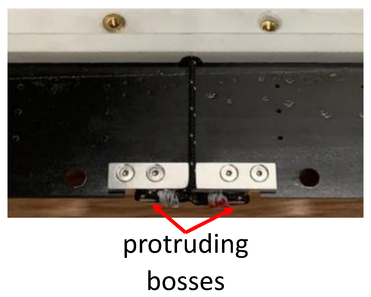
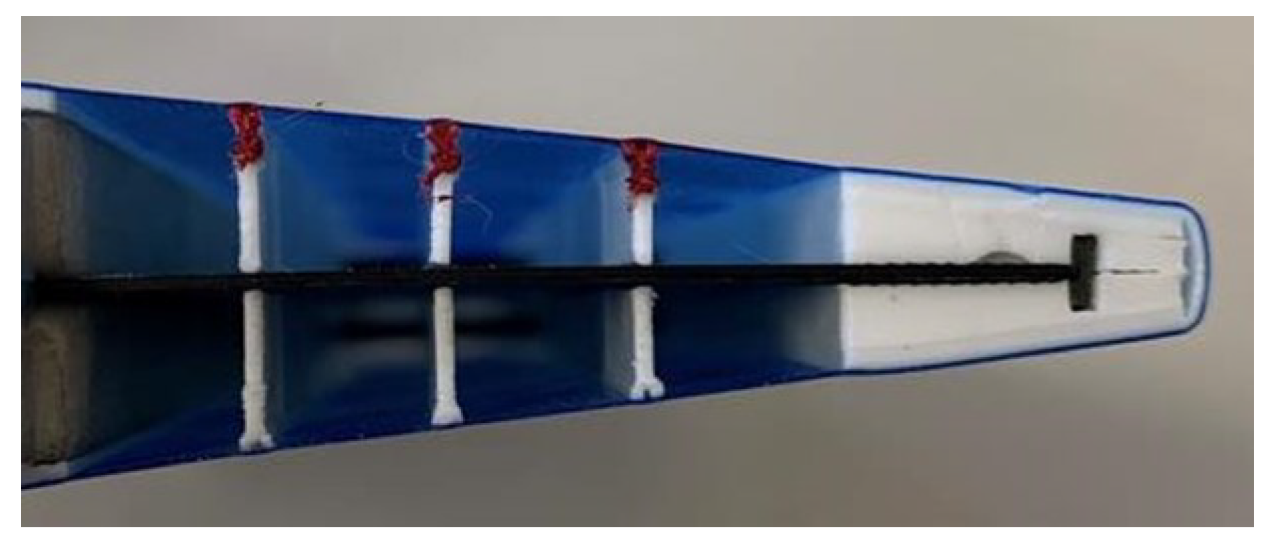
The multi-material FFF printing approach allows printing the stringers and mounting tabs directly onto the skin sheet, which are themselves 3D printed in the same process. This will ultimately make the assembly much simpler compared with previous FishBAC iterations, as the skin sheet no longer needs to be separately stretched and bonded to the stringers in a second operation. Moreover, the total part count is reduced. The removable design allows the removal of the skin panel for inspection or replacement with a different design altogether. Mounting tabs that run along the spanwise direction were printed onto the membrane from the stiffer formulation TPU. These tabs are used to mount the skin to the trailing edge and the main wing-body using standard metal fasteners. Both the upper and lower skin were printed in one single step and then folded over at the trailing edge. The spine is clamped between the printed trailing-edge tabs using transverse screws. On the main wing-body side, the skin is held in place with a dovetail self-locking feature that hooks into the 3D-printed wing shell. The dovetail helps during the assembly process and uniformly distributes the load from the stretching of the skin along the entire span to the wing-body. Once again, the tabs are screwed in place with transverse fasteners. To follow the design objective of having a removable skin, the stringers were stitched to the spine using aramid thread, thus avoiding the use of adhesives. Channels were printed along the stringers to allow a needle and the thread to be pushed through and slots within the stringers. These features aligned with holes that were drilled into the composite spine so that both the upper and lower skin portions can be stitched together.
The skin panel was further selectively reinforced with pultruded UD carbon fibre strips in key locations. It was found that the fasteners caused the tabs on both the wing-body side and at the trailing edge to warp, and due to the skin tension, the edges started to peel away from the wing-body and trailing edge. In order to stiffen the skin anchors and to better spread the load, a carbon fibre strip was embedded into the anchors with a spanwise orientation. A second carbon fibre pultrusion was also inserted at the end of the spine into a slot that spanned both the upper and lower portions of the skin’s trailing edge, stiffening the trailing-edge section and providing an alignment feature for the spine and skin portions.
Figure 7 shows the side view of the skin and stringers mounted on the wing.
3.4. Skin Panel Manufacture
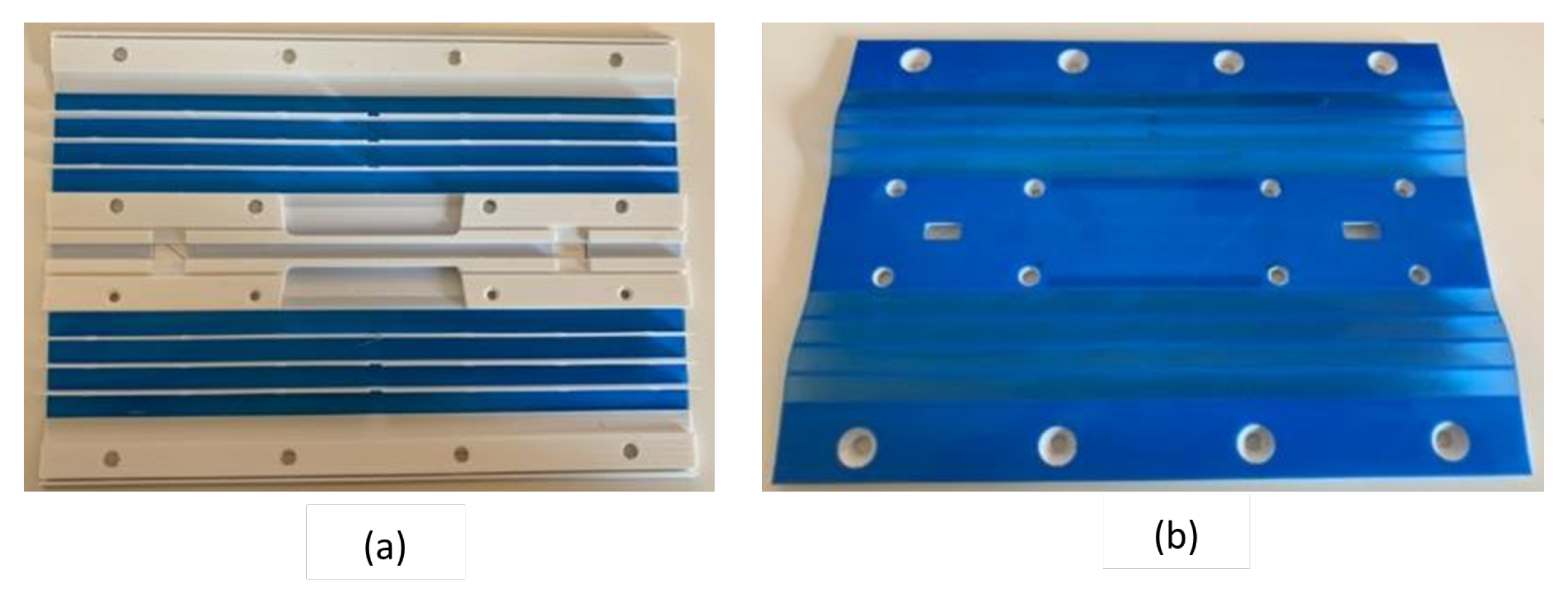
The skin panels (
Figure 8) were printed on an E3D Toolchanger FFF 3D printer using modified direct-drive extruders for flexible materials. Each material had its own extruder head so that the PID controller could be tuned for the materials printing temperature to avoid any temperature fluctuation throughout the print. Due to print size limitations, the individual panels for the wind tunnel demonstrator had to be assembled in four stages. These steps are described as follows.
Assembly of the tabs that screw into the main wing-body. Then, a 1 m-long, 3 mm × 1 mm carbon fibre strip was epoxied into a slot in the printed sections. The skin was held in place by screwing it to the main wing until the adhesive was fully cured. Release film was placed between the wing and the skin panel to avoid them getting permanently cured. The above steps were repeated on the opposite side.
Assembly of the trailing-edge section. Epoxy adhesive was applied to the spanwise ends of the stiffer TPU anchor pieces to create a single continuous panel. On one side and in an alternating fashion, the carbon fibre tabs were inserted using epoxy adhesive. Whilst still uncured, this entire assembly was screwed onto an especially designed assembly jig to ensure that all holes in the trailing edge will align once the adhesives are cured.
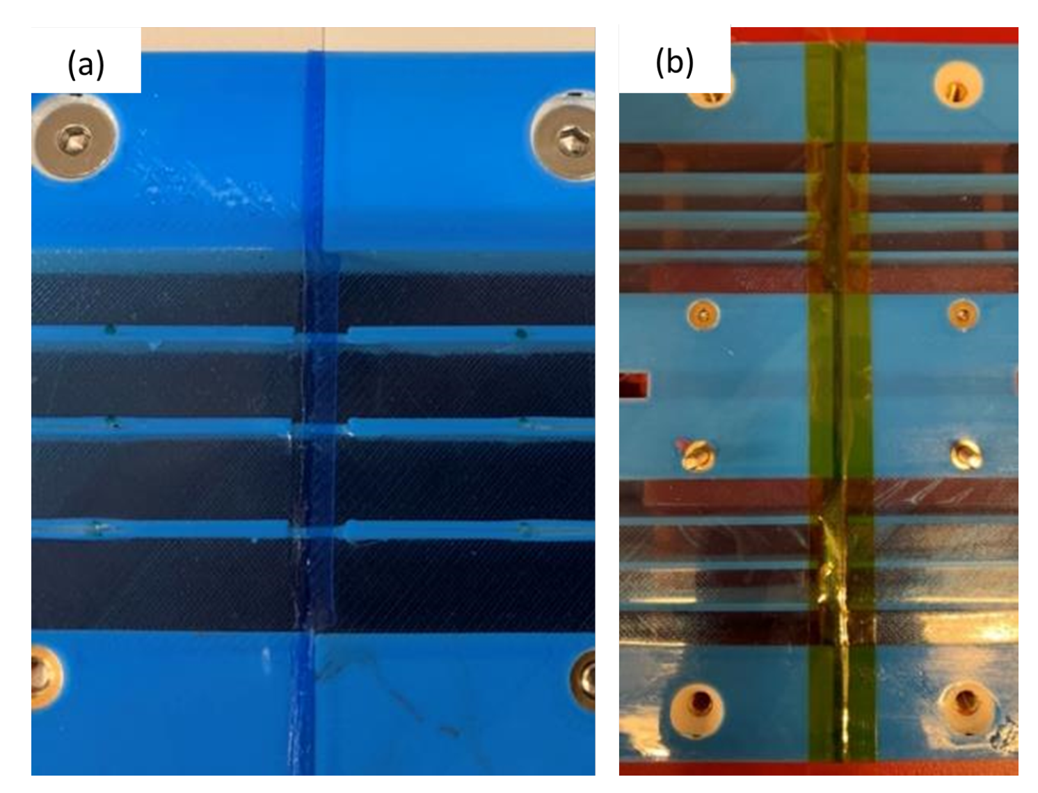
Thermoplastically welding the ends of the soft TPU skin membranes together to make a single air-tight skin surface. Kapton tape was temporarily placed over the joints to promote a smooth weld. A soldering iron with a specially shaped tip was drawn over the Kapton tape to melt and consolidate the adjacent skins together, as shown in
Figure 9.
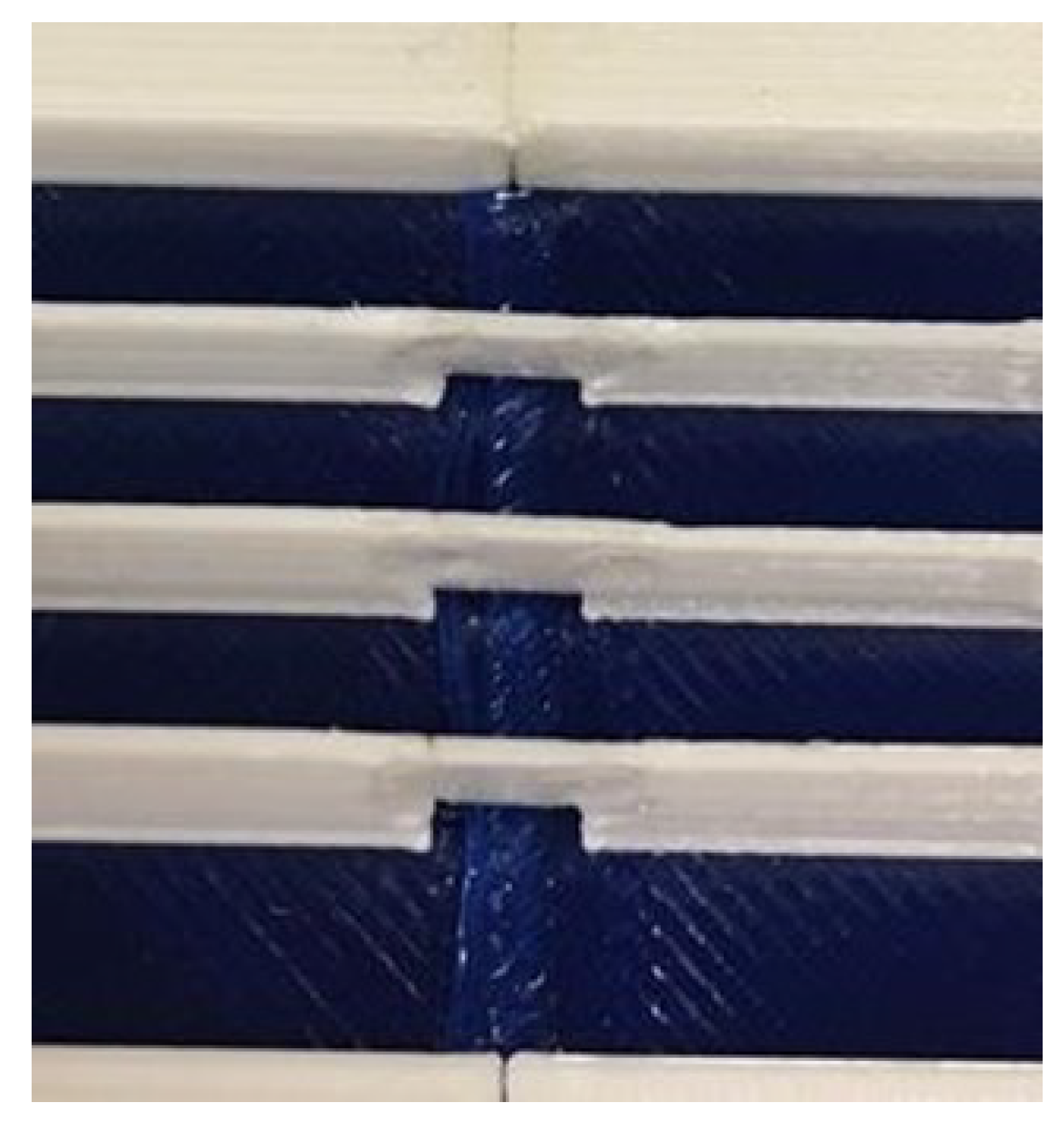
The final stage was to weld the stringers together. Pieces were printed to bridge between the two neighbouring panels stringers. They were then welded in place using a spot-welding technique, as shown in
Figure 10.
Figure 9.
(a) Fully finished weld. (b) Weld covered in Kapton tape ready to be welded.
Figure 9.
(a) Fully finished weld. (b) Weld covered in Kapton tape ready to be welded.
Figure 10.
Welded stringers.
Figure 10.
Welded stringers.
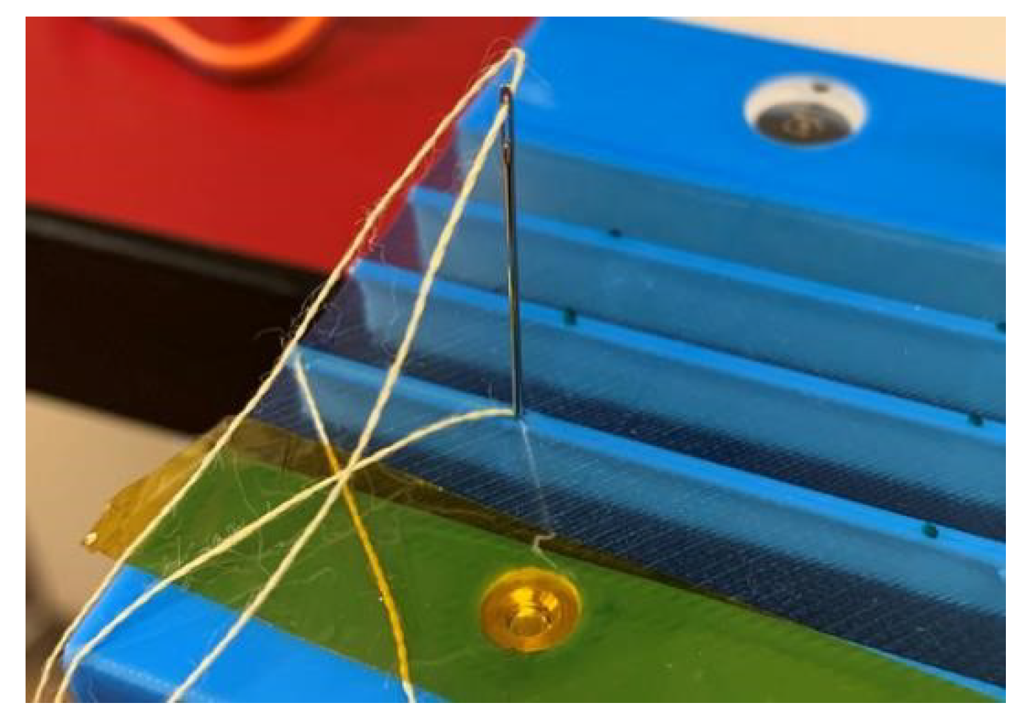
Once the skin panels were fully connected together, the final step in the manufacturing process was to attach them to the wing structure and stitch them to the spine. The skin panel was first folded around the trailing-edge fold and the screwed hand tight to the spine. The wing was then actuated to the maximum deflection to facilitate the pre-tensioning of the skin panels. The tab was screwed down hand tight. This was repeated on the opposite side, and once the alignment was checked, all fasteners were tightened. With the skin firmly attached to the wing, the skins were stitched to the spine. Pliers were used to force a needle with Kevlar thread through the narrow passage between the skin and the stringer. The holes of the opposing skins and the stringers aligned well, as the skin was under tension, which made stitching through the spine relatively straight-forward, as shown in
Figure 11. It was made sure that the thread was always under tension as it was not possible to tension once stitched along the entire span due to frictional locking. The thread ends were tied up around a hole in a stringer and then secured using a quick-drying fastener lacquer.
3.5. Construction of the Non-Morphing Wing Portion
The primary design goal of this underlying wing structure is to create a rigid, well-defined external geometry that is simple to make and sufficiently strong. The underlying structure is, therefore, designed around machined aluminium 6080-T6 parts. An aluminium box spar of dimensions 19.05 mm × 19.05 mm × 3.25 mm is centred at the quarter-chord of the airfoil section and acts as the main load bearing member of the structure. To create the desired airfoil geometry, two 3D-printed plastic covers are attached to the box spar to match the NACA 23012 airfoil. These two plastic covers, as well as the leading-edge sections, were 3D printed by Selective Laser Sintering (SLS) additive manufacture technique, using Glass-Filed Nylon 12 (also known as PA 12). To attach the nose leading edge to the front spar, a 15.88 mm × 6.25 mm aluminium bar with M4 tapped holes was used to clamp the two together using M4 screws. Additionally, an aluminium channel spar with dimensions 16.01 mm × 15.88 mm × 1.59 mm was added toward the trailing edge at the chordwise location to serve two main purposes: (i) provide additional strength and stiffness at the trailing edge where the FishBAC is mounted and (ii) support and react the actuation loads from the actuation mechanism that is mounted to both spars.
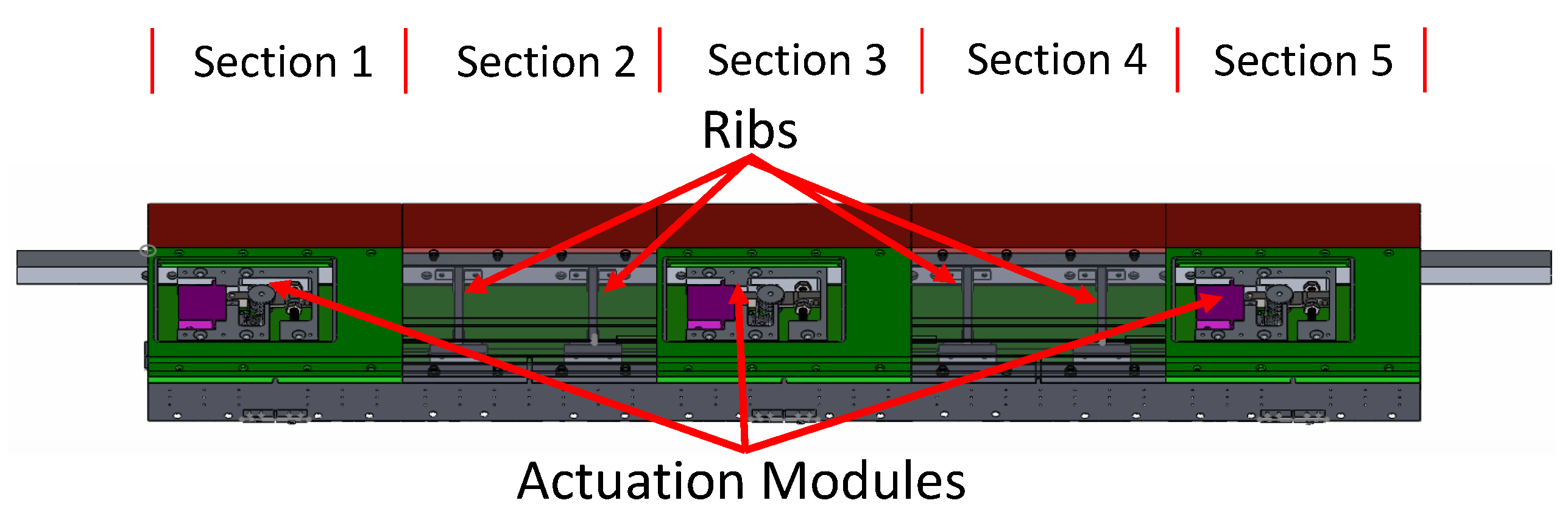
Five fibreglass-filled Nylon 12 parts spanning 199 mm constitute the sections along the wing-span and are printed to add up to the 995 mm wingspan. The actuator and actuation mechanisms (i.e., pulleys, bearings, tensioning mechanism) are mounted to an aluminium frame that is referred to as the ‘actuation module’. This actuator bracket is itself mounted to both box and channel spars, ensuring full load transmission between the main load bearing members of the wing. Since there are only three actuation points in this wing, there are only actuation modules at the spanwise
Section 1,
Section 3 and
Section 5. Furthermore,
Section 2 and
Section 4 each have a machined aluminium rib connecting the two spars to add additional strength and stiffness (see
Figure 12). To create easy access to the actuation mechanism for any required removal or replacement of components, an access panel was designed into the lower surface of
Section 1,
Section 3 and
Section 5. These are attached to the actuation module by using a series of countersunk screws. A detailed description of the actuation mechanism will be presented in the following subsections.
4. Material Testing
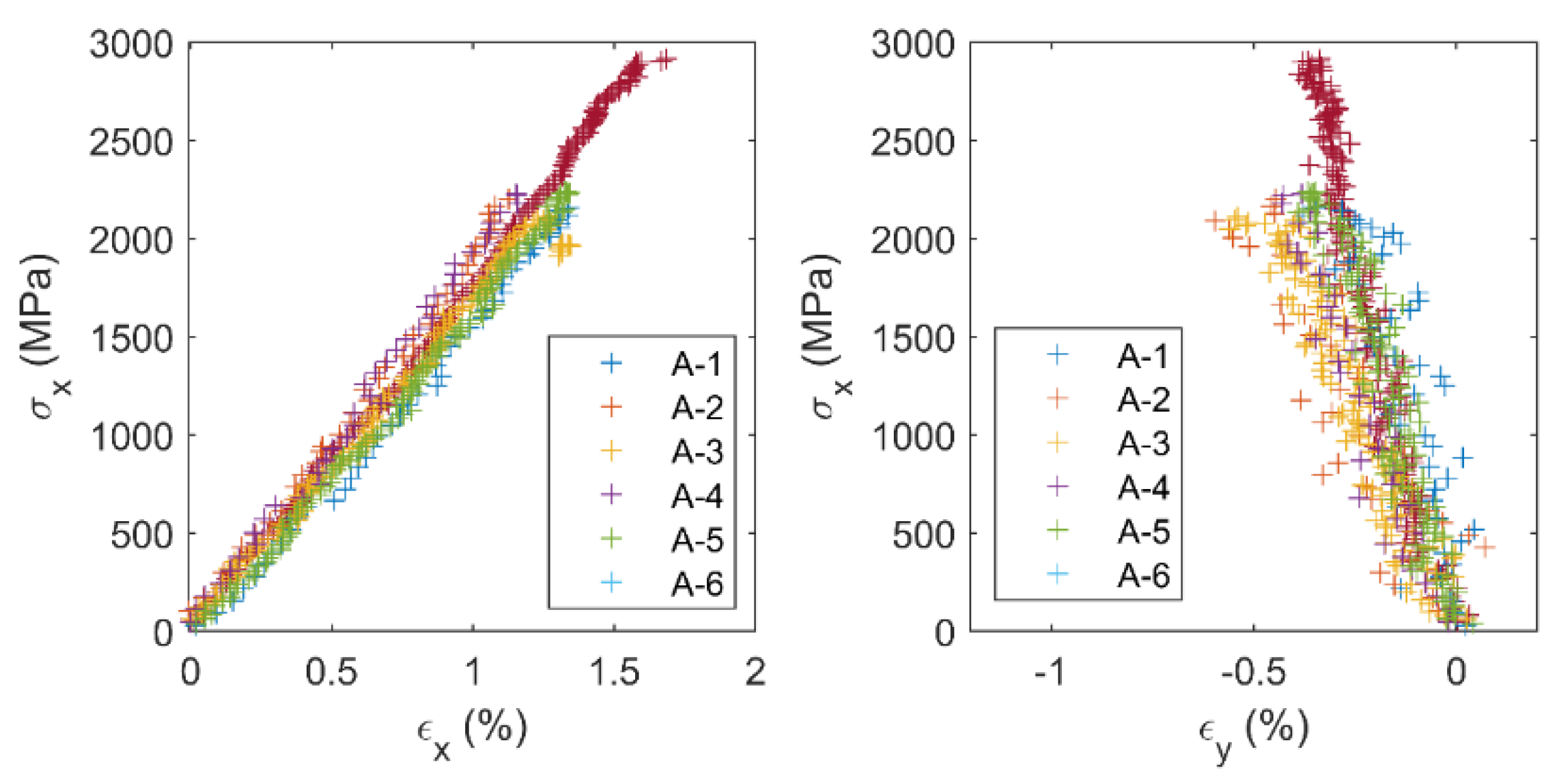
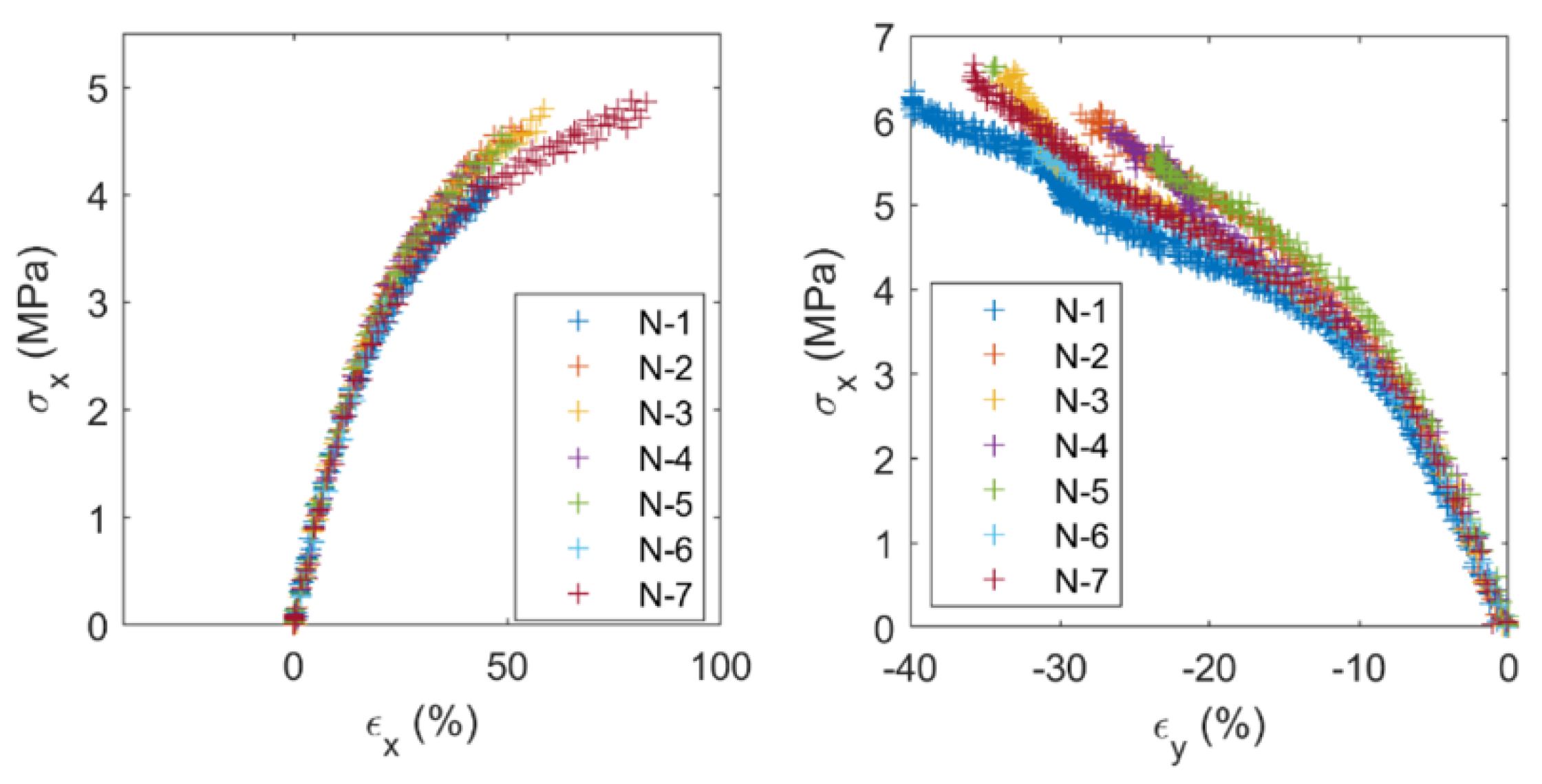
To obtain the properties of the materials manufactured by the authors, the following tests were performed: (a) carbon fibre axial, transverse and shear tensile tests, and (b) Armadillo TPU (stringers) and Ninjalfex TPU (skin) tensile tests.
The material properties of the 8552/IM7 Unidirectional (UD) carbon fibre prepreg were obtained by following the ASTM D3039 [
28] and ASTM D3518 [
29] Standards for tensile and shear properties of fibre-reinforced polymers, respectively, whereas the skin and stringer materials were tested in accordance with ASTM D638 Standard for tensile properties of plastic [
30]. To measure both axial and transverse strains, an Imetrum Video Gauge point tracking optical system was used. This system consists of one camera that is placed perpendicular to the test specimen’s in-plane face. By tracking points within this face, the in-plane axial and transverse strains can be obtained. Along with the loads measured by the test machine’s load cell and the specimen dimensions, these strains can be used to obtain stress–strain curves. From these stress–strain curves, the fibre-direction (
), matrix-direction (
) and shear (
) modulus can be obtained for the CFRP specimens. Additionally, the in-plane Poisson’s ratio (
) can be obtained from both (
) and (
). Since both skin (Ninjaflex) and stringer (Armadillo) materials are isotropic, only
E and
are obtained from experimental data, and
. A summary of all the experimentally measured material properties can be found in
Table 2.
Figure 13 and
Figure 14 show examples of the carbon fibre axial and the Ninjaflex tensile tests, respectively.
5. Structural Test: Skin and Stringers Panels
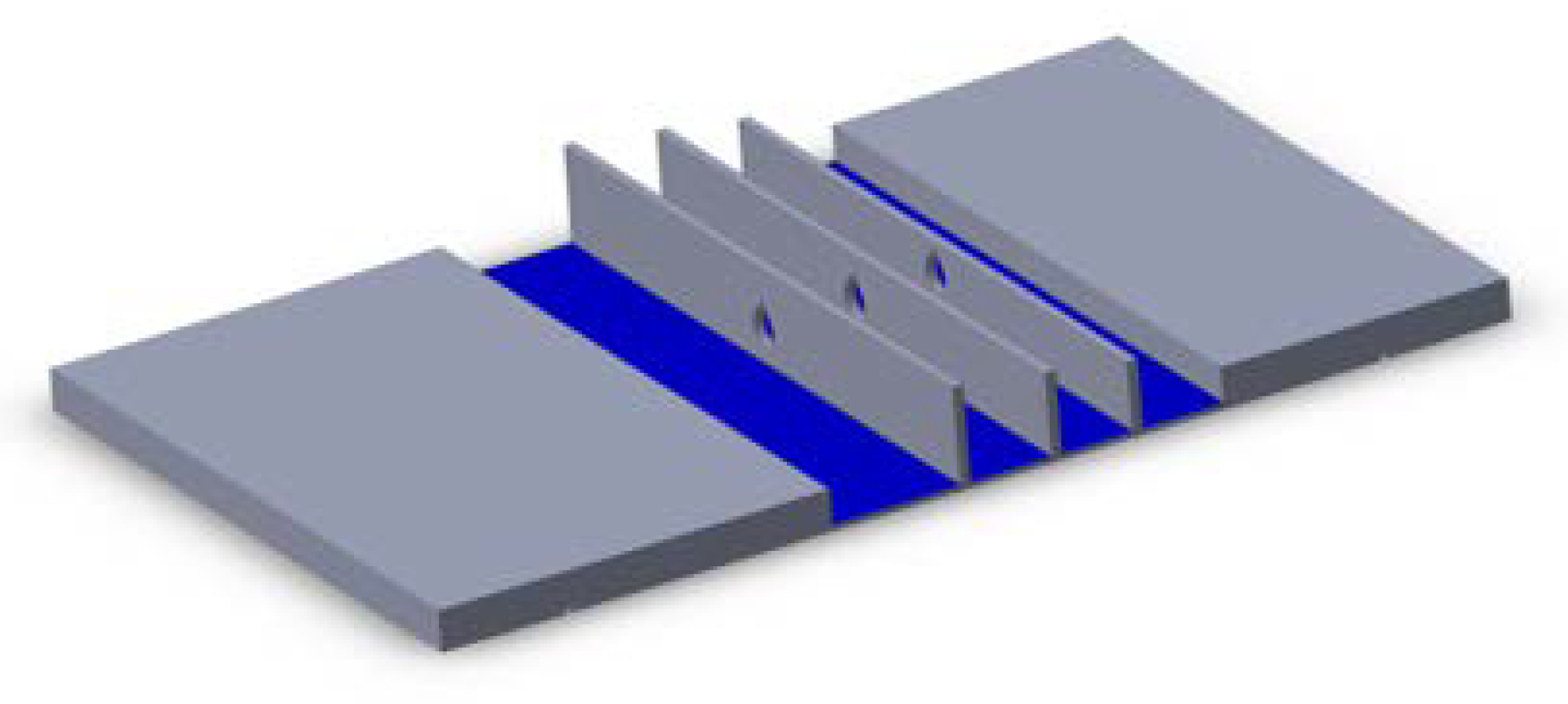
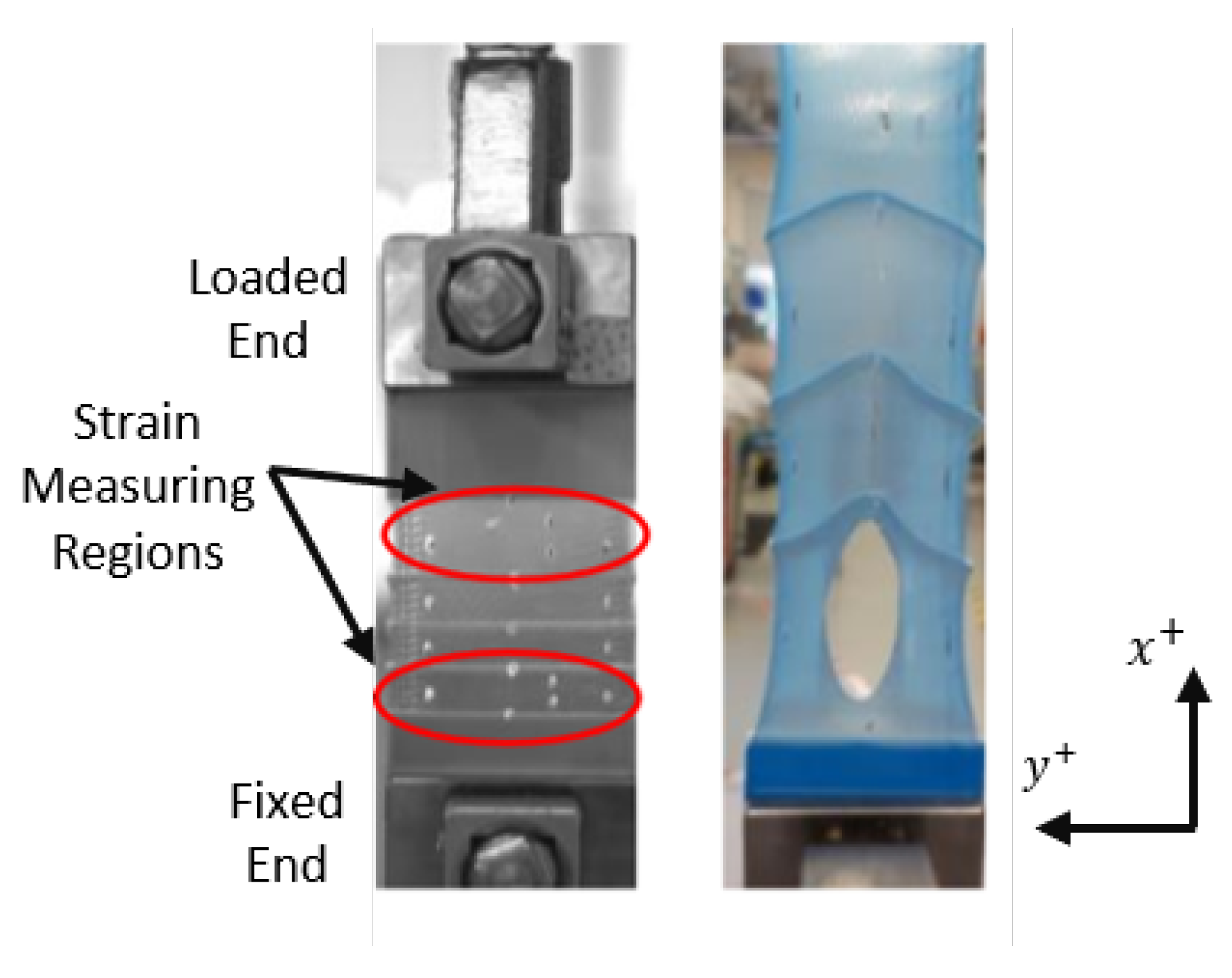
One of the riskier aspects of this FishBAC wing design is producing the skins and stringers by additive manufacturing, using two different materials in a single print. To de-risk this design feature, a feasibility study was performed by 3D printing a series of skin/stringer test coupons and testing them under tension. This experiment allows testing the interface between the stringers (Armadillo) and the skin (Ninjaflex), in a configuration akin to the FishBAC’s skin/stringers structure. A series of 50 mm × 87 mm skin/stringer test coupons were used in this experiment (
Figure 15). With a total of three stringers with a spacing of 7 mm between them, these coupons resemble the FishBAC skin dimensions. Each one of the specimens was tested under tension using a Shimadzu tensile machine fitted with a 1
load cell.
An Imetrum Video Gauge point tracking optical system was placed perpendicular to the test specimens to measure in-plane strains. In this test, strains were measured in two different regions: (i) between the fixed end of the specimen and the first stringer, and (ii) between the loaded end and the third stringer.
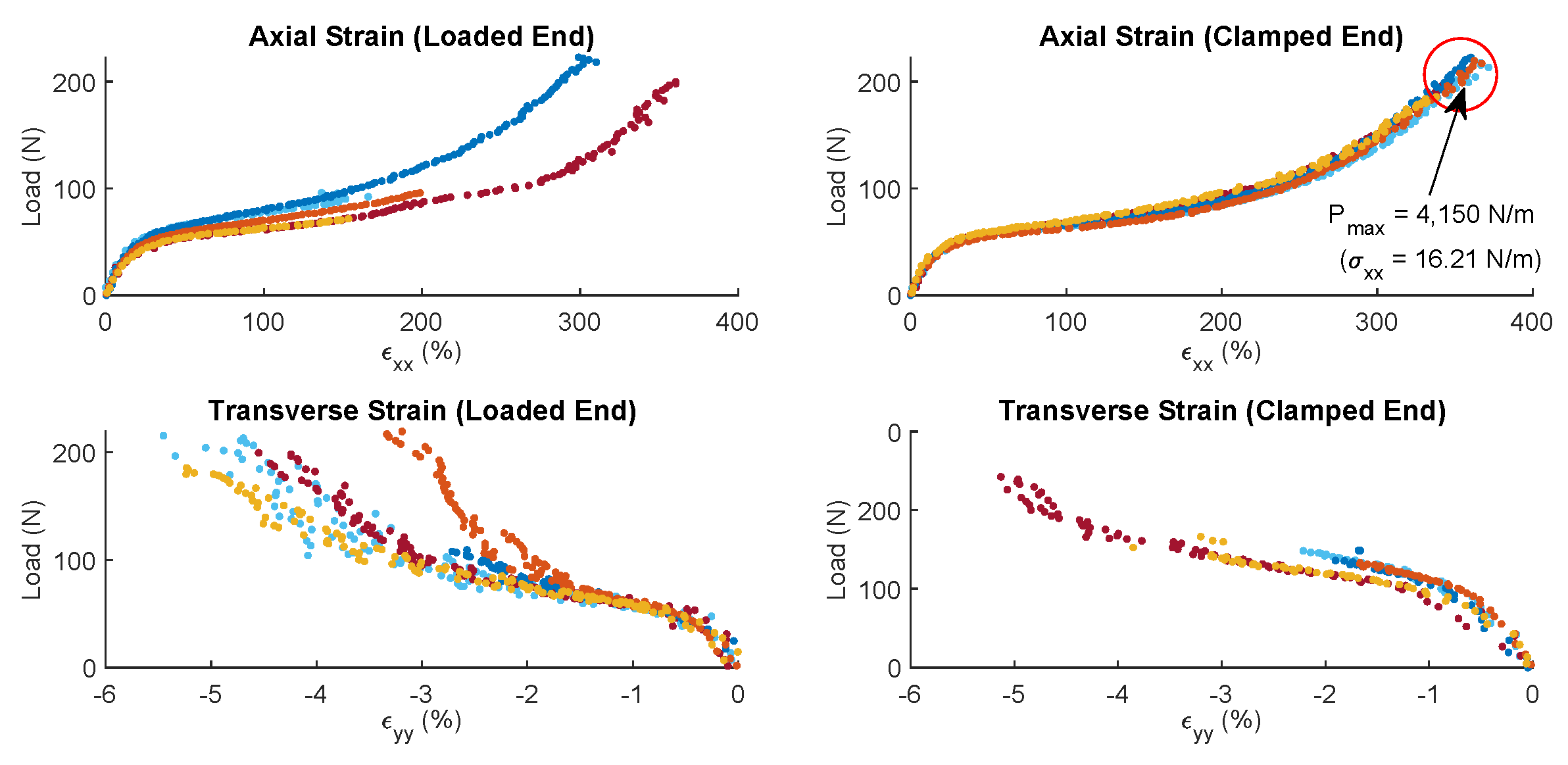
Figure 16 shows strain–load curves for these specimens. The results show that these skin/stringer panels can be strained up to 400% before ultimate failure is reached. Furthermore, it was observed during the test (
Figure 17) that these structures fail between stringers. However, it is important to note that the damage propagates very slowly and that it takes a significant amount of energy from the point where damage starts to be observed to the point where the structure catastrophically fail. These results are very positive due to two main reasons:
(a) the FishBAC’s skin is pre-stretched by 15% and will see roughly another 10% strain during operation, and so the required strains are very far from failure and
(b) any cracks or surface damage on the skin should not lead to catastrophic failure at these strain levels. Therefore, the two-phase skin/stringer panels were deemed safe to use in this wind tunnel experiment.
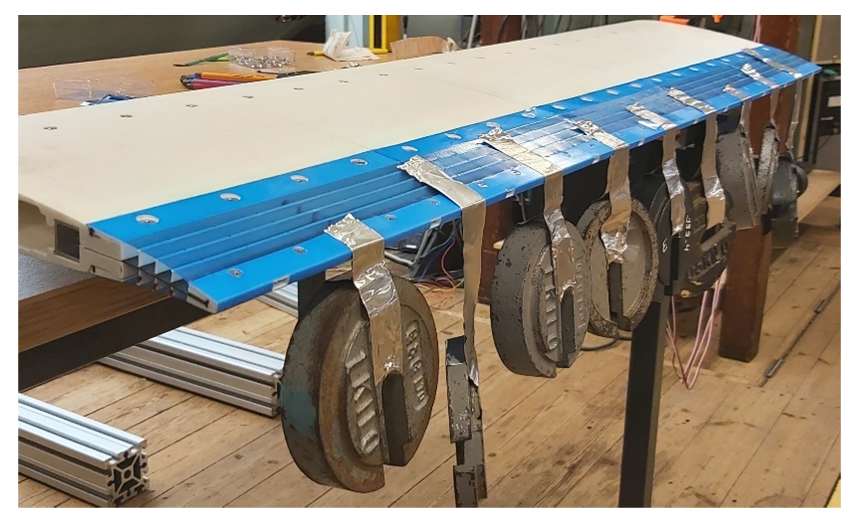
6. FishBAC Static Structural Test
The robustness of the FishBAC was verified by performing a benchtop mechanical loading test. The structure was loaded discretely using point masses. A total of
in hanging masses (i.e.,
at each 200 mm along the span) were attached to the FishBAC (
Figure 18). This loading was selected based on the maximum root bending moment that the FishBAC will experience at the test speed of 30 m s
−1, at its maximum camber deflection and highest expected lift coefficient, with a factor of safety of
. Additionally, the FishBAC was actuated to its maximum upper and lower deflections while the weights were still in-place, to verify the device’s structural robustness. Since the structure successfully resisted this proof load test, the devices were said to be safe for wind tunnel testing at 30 m s
−1.
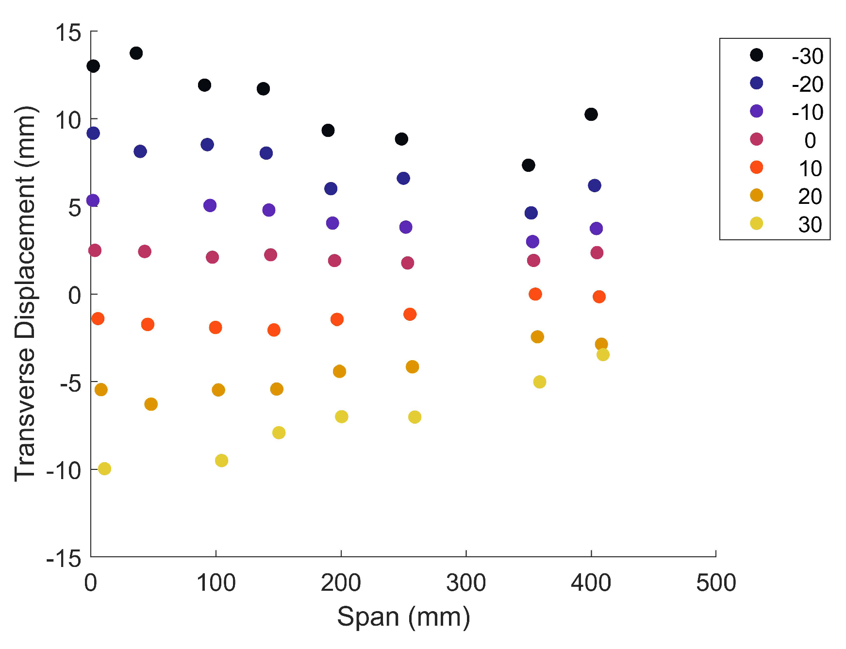
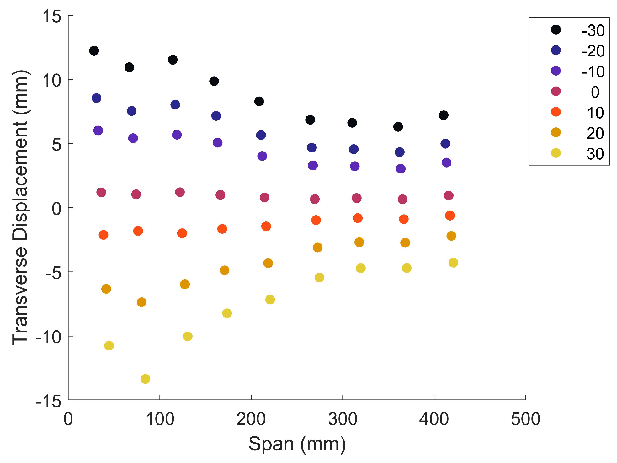
Additionally, to assess the structural and actuation behaviour of the FishBAC wind tunnel wing model in the absence of aerodynamic loads, an actuation test was performed to estimate the transverse deflections that different actuation inputs generate. An Imetrum ICA-3D-1000-03 UVX 2-camera stereo video gauge point tracking system was used to track the displacement along the trailing edge of the FishBAC. Nine 5.6 mm diameter tracking target stickers were attached to the trailing edge, with a spacing of around 50 mm between each one of them. All three actuators were run in a synchronous way, with actuation inputs ranging from −30° to +30° in increments of 10°.
The point tracking system tracks the position and displacement of each target point.
Figure 19 shows the transverse displacement at the spanwise edge in the absence of aerodynamic loads. It can be observed that transverse deflections of approximately
can be achieved. This deflection range matched the desired output, which was chosen based on previous work on optimal deflections for minimising power requirements on the B0-105 rotor system [
32]. It is worth mentioning that due to measuring volume limitations of the point tracking system, the full span could not be recorded, instead a 400 mm section of the span was used.
7. Wind Tunnel Test
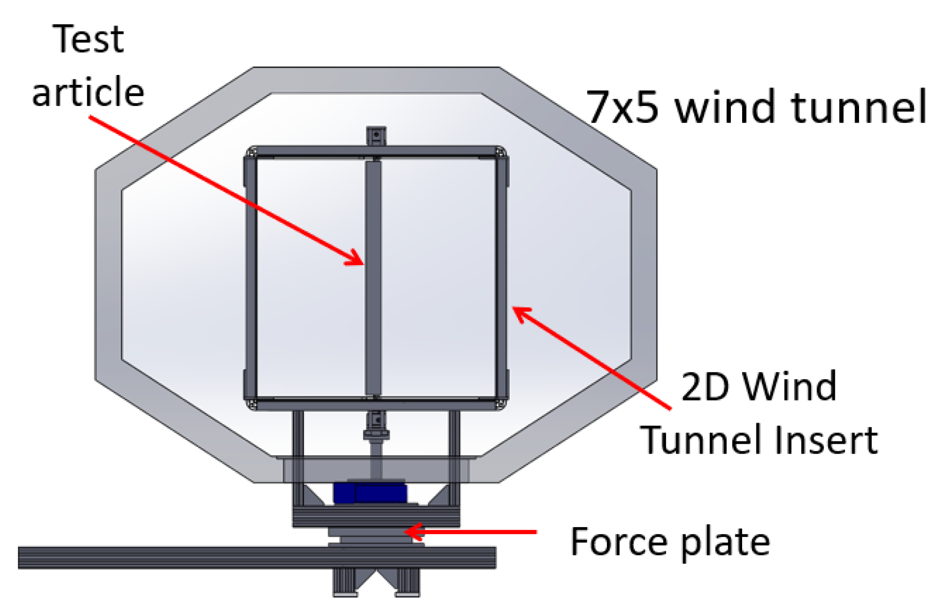
A quasi-2D wind tunnel experiment was performed to assess the aerodynamic performance of the FishBAC device introduced in this article. This experiment was conducted in the University of Bristol’s 7 ft × 5 ft low-speed wind tunnel. Since the University of Bristol’s 7 ft × 5 ft low-speed wind tunnel was not previously set up to perform two-dimensional wind tunnel experiments, the facility had to be adapted. A 2D wind tunnel insert was designed and built in-house and was equipped with off-the-shelf instruments and sensors to measure the forces and moments of the different wing models.
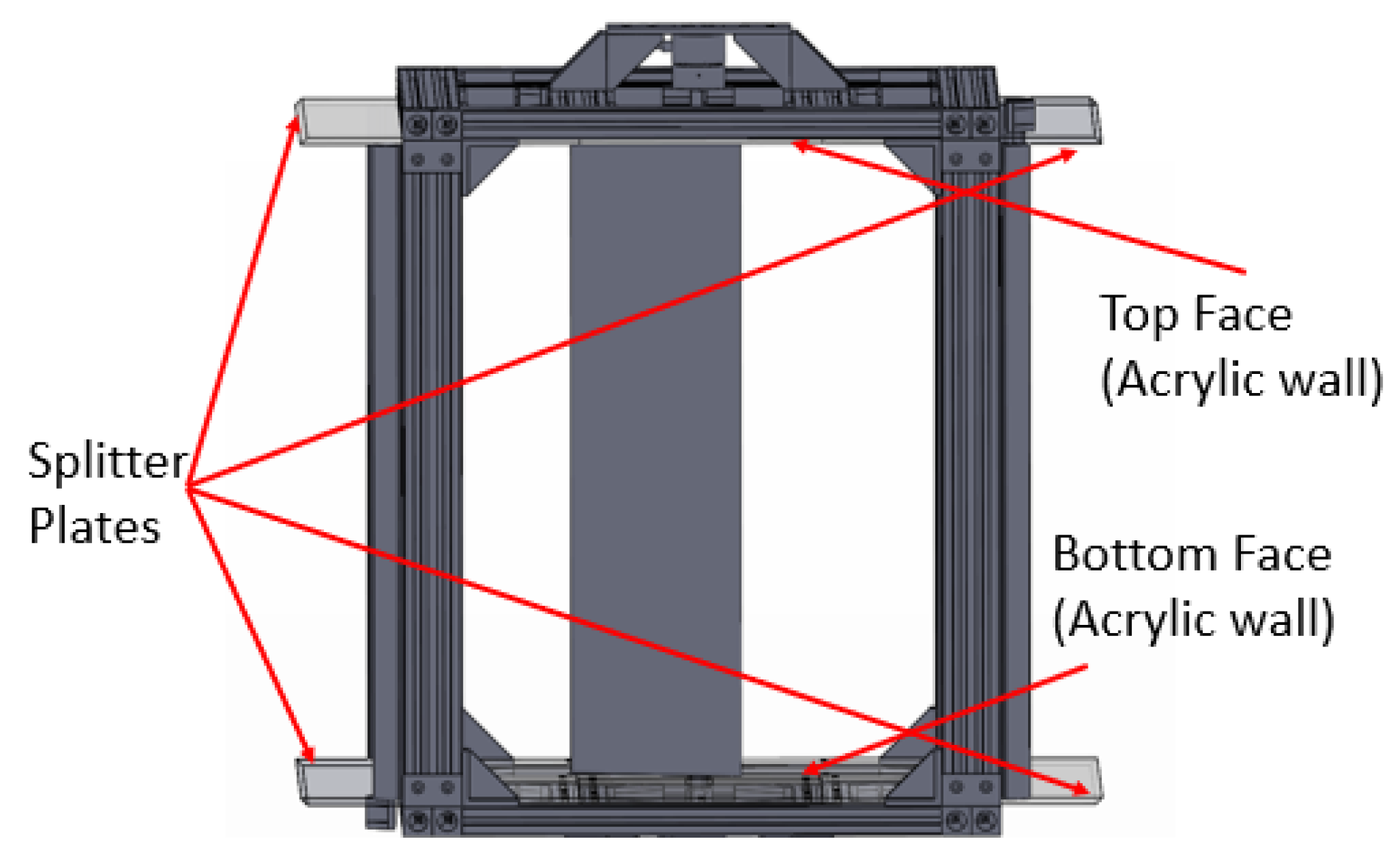
7.1. Wind Tunnel 2D Insert
A bespoke 2D wind tunnel insert with a 1 m × 1 m cross-section by 1.2 m-long test section was designed and built. The 2D insert consists of two splitter plates made of 10 mm thick acrylic sheets mounted on square frames and four vertical uprights connecting them and mounting the wing section. This frame is made from extruded aluminium slotted rail sections for ease of assembly and modification. The uprights support the top splitter plate and maintain the 1 m section height. Moreover, the connections at all corners are made of four distinct brackets, each to ensure high rigidity and strength (
Figure 20). The bottom splitter plate is mounted to a base frame, where the automatic pitch drive system also sits, through four shorter vertical extrusions that lift the cube-like structure to the centre of the tunnel section (
Figure 21). The splitter plates work as walls for the reduced test section where 3D effects are reduced, and a desired quasi-2D flow is produced on a 1 m span. The leading and trailing edges of the splitter plates were cut at a 45° angle to cleanly cleave off a fresh boundary layer. The two sides, which correspond to the walls on the suction and pressure side of the flow, are open, allowing the free expansion of the freestream along the airfoil thickness.
A precision right-angled worm gearbox driven by a synchronous servo motor was installed with the axis in a vertical orientation and used to control the wing’s pitch angle. An industrial digital drive with 6 rated output was installed to drive the servomotor and set up with closed-loop control of position and analogue output to be acquired during testing. The servo produces a stall torque of 2.9 Nm with a resolver measurement accuracy of and is equipped with a braking system. The two-stage worm gearbox has a reduction ratio of 400:1 and can support a maximum axial load of 25 . The system was designed to produce a maximum pitching torque of 100 Nm and operate between 0.1 and 12 rpm, with an overall accuracy of 0.0667° (driven mostly by gearbox backlash). The dedicated software has been set up to perform sequential tasks corresponding to the angle ranges and step increases defined for each test.
Two ME-systems K6D80 6-axis force sensors with a forces and moments range of 2 and 100 Nm, respectively, were used to measure the aerodynamic forces and moments acting on the wing. Two load cells are required to fix the demonstrator at both ends and obtain 2D aerodynamic coefficients. The top force sensor was mounted to the 2D insert using a series of aluminium brackets and is integral with it, whereas the bottom force sensor was attached to a shaft connected to the pitch drive that rotates inside a flanged bearing to change the wing’s pitch angle. Mounting and attaching the wing directly to both force sensors allows bypassing the aerodynamic forces acting on the 2D insert (e.g., additional drag). However, this setup does not eliminate the effect that the presence of the uprights may have in terms of flow quality and smoothness.
Furthermore, the entire 2D insert structure is mounted to an AMTI Biomechanical Force Platform (1000 lbs max measurable force), which measures the forces and moments that the entire setup experiences during the wind tunnel test. The force plate is fixed to a foundation frame that connects to the wind tunnel structure. These forces and moments are measured as a ‘backup’ to the wing’s force sensors. Therefore, this data set would only be used if the force sensors present any issues. Additionally, two pitot tubes were mounted to the two front uprights (i.e., facing the inlet of the test section) to measure the local flow velocity where the quasi-2D flow is produced. Each pitot tube is connected to one NXP MPXV7002 differential pressure sensor, which measures the dynamic pressure. Due to blockage (around 10% for the 2D insert plus wing), the flow velocity inside the 2D test section is around 10% higher than the wind tunnel’s speed (measured upstream the wind tunnel test section). Therefore, the local freestream velocity inside the 2D insert is used for all aerodynamic coefficient calculations. Furthermore, two thermocouples were placed on each pitot tube to record the temperature during testing. Lastly, an NXP MPXA6115AC6U 115 Absolute Pressure Sensor was used to record the atmospheric pressure. This measured pressure, along with the temperature measurements, was then used to calculate the air density. Lastly, for safety purposes, two accelerometers were installed to the 2D insert to monitor vibrations.
7.2. Results: Aerodynamic Forces and Moments
The main objective of this wind tunnel test campaign was first, to ensure that the novel design and manufacturing techniques introduced in this latest generations of FishBAC wings lead to structurally sound FishBAC devices that can resist the different aerodynamic load cases, and second, to evaluate its aerodynamic performance and its ability to generate changes in lift coefficient with varying camber distribution (i.e.,
). It is worth mentioning that, since (a) this wind tunnel setup consists of a 2D wind tunnel insert inside the 7’ × 5’ test section and (b) no local 2D drag measuring technique was implemented (e.g., wake rake), the drag measurements are expected to be higher than a purely 2D case. To correct for three-dimensional effects, standard wind tunnel corrections are applied to account for solid blockage and streamline curvature. Because the 2D insert is a closed section with no top/bottom covers (i.e., both suction and pressure sides are left open), the wake blockage is assumed to be zero. The correction factors implemented in this study are the classical ones given by [
33]. All measurements were conducted at a freestream velocity (inside the insert) of 30 m s
−1, which results in Mach and Reynolds numbers of
and
, respectively.
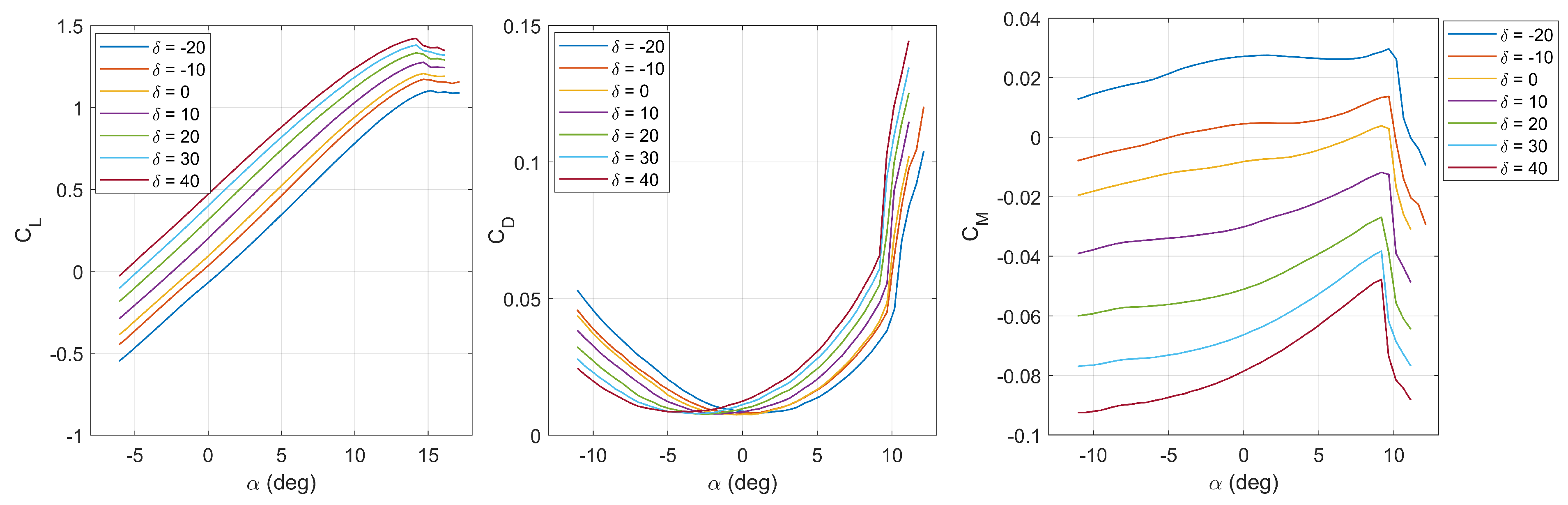
Figure 22 shows a very clean set of data, where each increment in the actuation input angle generates a substantial change in lift coefficient. A maximum
is observed in the linear region of the lift curve (i.e., for angles of attack of less than α < 10°), whereas a
is observed at around stall. Additionally, it is seen that the point of minimum drag does shift with increasing camber deflections, which is consistent with the results observed by [
24]. However, it is worth noting that these drag coefficient results vary significantly with the angle of attack, which is not expected in a 2D wind tunnel test. Two-dimensional drag coefficients should remain relatively unchanged with increasing pitch angle (at a given camber deflection) when the flow is attached (i.e., in the linear region of the lift curve), and then “spike” as the flow starts to separate and stall (see [
24] for example). These drag results suggest the presence of 3D effects that standard wind tunnel corrections ([
33]) cannot correct. These 3D effects might have been introduced by the 2D insert inside the 7’ × 5’ tunnel section; therefore, they are most likely a limitation of the setup. Despite the lack of high-quality 2D drag measurements, it is interesting and encouraging that the minimum value of drag coefficient for any given morphing deflection is relatively constant, implying that the change in camber is essentially shifting the drag curves left and right by a consistent offset in the angle of attack. Lastly,
Figure 23 shows that the FishBAC can be used for controlling pitching moment coefficients. A
can be achieved by varying the camber distribution, which highlights the potential that the FishBAC has for use in moment driven control surfaces, such as servo flaps.
7.3. Displacements and Actuation Power Measurements
Displacements under both actuation loads and freestream airflow were measured using the same two-camera point-tracking system described in
Section 6. Additionally, three (one per actuator) LEM® 6
CASR 6-NP Hall Effect current sensors are used to determine their power consumption. These sensors measure the strength of the magnetic field induced by the current flow through the actuator leads and generate an output voltage that is directly proportional to the magnitude of current—at a rate of
mA V
−1. A detailed explanation of this methodology can be found in [
24]. Since the actuator voltage supply was also recorded, the power draw of each actuator can be calculated as the product of amperage and voltage.
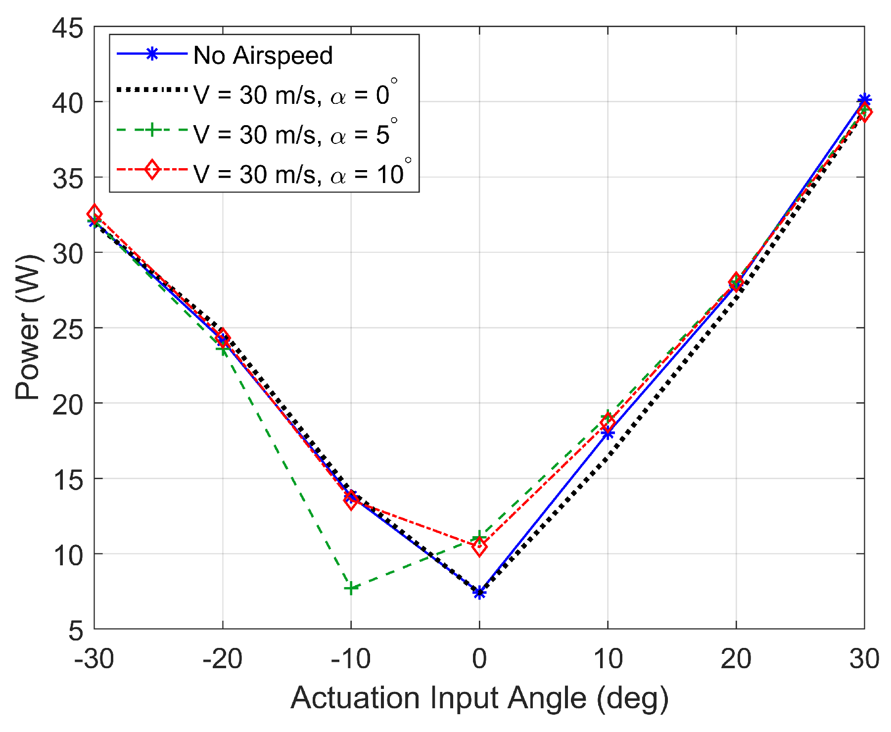
Figure 23 shows the transverse displacements of the trailing edge (spanwise) when the freestream velocity and angle of attack are 30 m s
−1 and 0°, respectively. It is observed that the transverse displacements show very similar trends as in when the aerodynamic loads are absent (see
Figure 19), which suggests that the achievable displacements are not limited by the amount of torque available, but by the servo’s operating range, which determines the pulley angle rotation at each tendon. Additionally,
Figure 24 shows variations in actuator current draw as a function of actuation input angle and at different pitch angles. It is observed in this figure that the power draw does not significantly vary when aerodynamic loads increase, implying that the structural stiffness is significantly more dominant in the overall load than the aerodynamic stiffness.


