1. Introduction
The presented paper focuses on an implant widely used in traumatology, namely a headless (so-called Herbert) screw. This screw (implant) is designed for surgical treatment of a fifth metatarsal bone using osteosynthesis. In general, osteosynthesis is a surgical method of treating fractures involving the fixation of bone fragments using internal (screws, splints, nails, wires, and combinations thereof) or external (external fixators) implants. The application of screws is important in the surgical treatment of complicated human or animal fractures and deformities in trauma or orthopedics. They serve both external and internal fixation in osteosynthesis, etc. Osteosynthesis in trauma surgery is a recognized and important medical method and an important topic of many studies [
1,
2,
3,
4,
5,
6,
7,
8,
9,
10,
11].
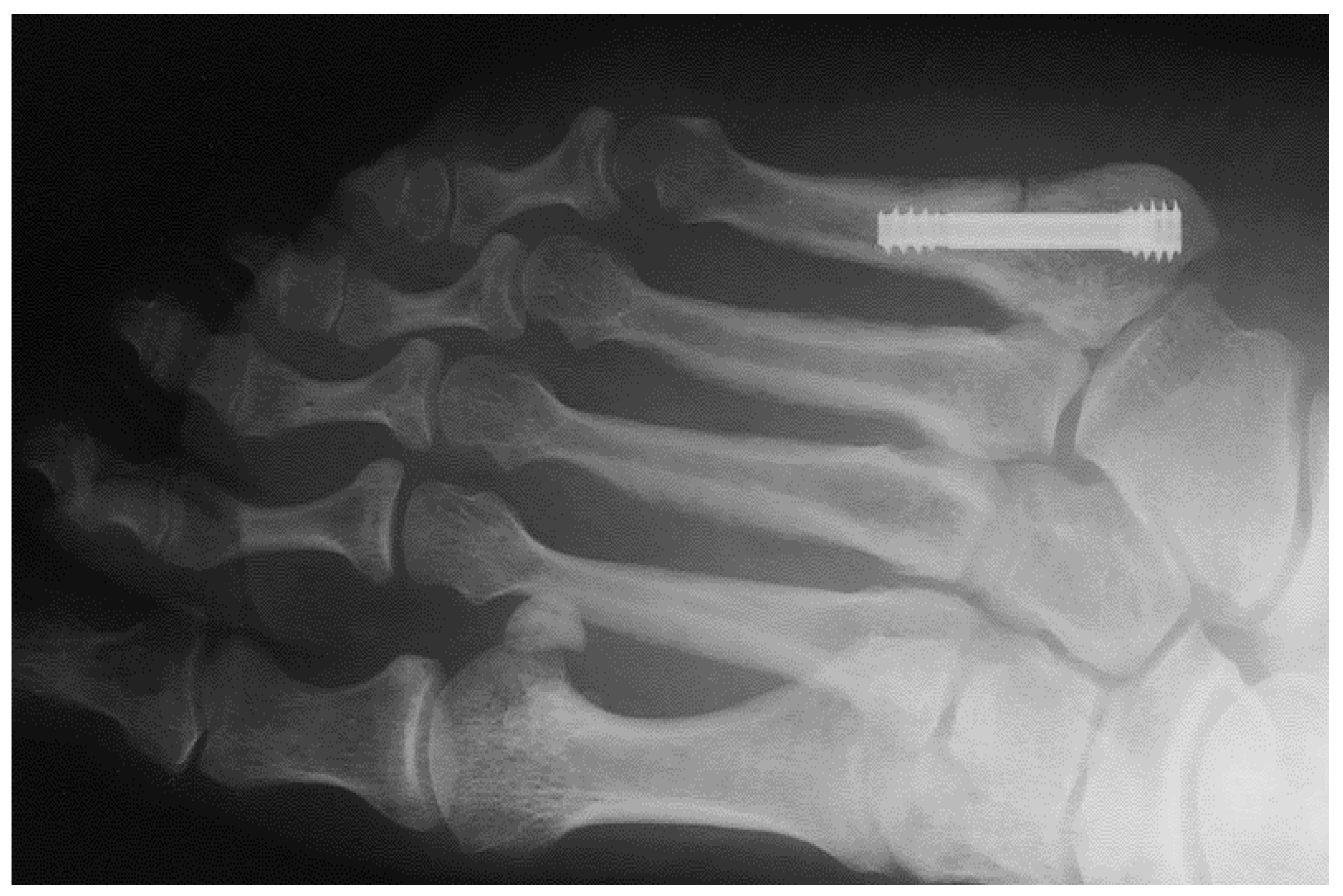
Figure 1 shows an X-ray snapshot of the fixation of a fifth metatarsal fracture with a headless screw. Metatarsal fractures are the most common fractures of the leg, the most common among them being the fifth metatarsal fracture. Metatarsal fractures are mostly caused by direct impact (car accident, fall, etc.) or during sports (typical injuries of football players, etc.). There are multiple types of metatarsal fractures, such as the Jones fractures, proximal diaphyseal, or fatigue fractures. Interested readers may find more information in [
5,
6].
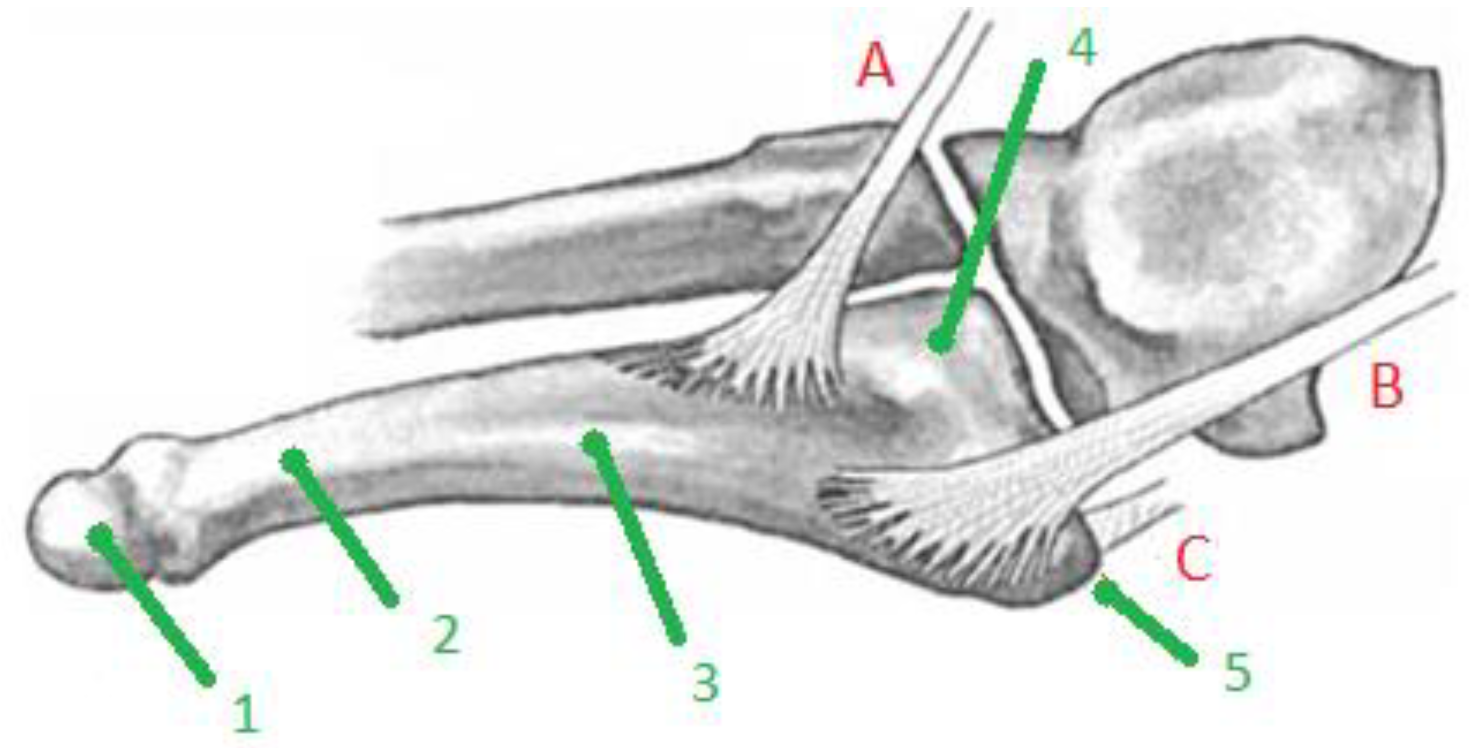
Figure 2 indicates the basic anatomy of the fifth metatarsal bone and its surroundings.
In 1902, Sir Robert Jones described his own foot injury, which he suffered while dancing. It was a transverse fracture of the fifth metatarsal, without substantial dislocation in the junction of the diaphysis and metaphysis of that metatarsal; see
Figure 2. This fracture is characterized by injury development caused by relatively low stress, minimal swelling, absence of hematoma, and prolonged healing. The classification of fractures in the proximal part of the fifth metatarsus is not uniform and completely clear. Some authors fundamentally differentiate the so-called true Jones fracture from stress fractures (fatigue fractures) of the proximal diaphysis of the fifth metatarsal. In 1960, Stewart reported that a large proportion of patients experienced prolonged healing or developed pseudoarthroses after the conservative treatment of the Jones fracture. Their study group, however, contained a large proportion of fatigue fractures of the body of the fifth metatarsal; see [
5,
6] or [
11,
12,
13].
Both conservative and surgical treatment of the fracture of the proximal part of the fifth metatarsal is possible. In conservative therapy, the application of a full, non-weight-bearing cast or plastic fixation for 6–8 weeks is recommended. In surgical treatment, intramedullary screw fixation or osteosynthesis with a tension loop wiring is used. Spongioplasty or corticospongious graft application is often considered the method of choice for these fractures [
5,
6,
11,
12,
13].
In 1962, Timothy J. Herbert started to use a compression screw he designed for the surgical treatment of scaphoid fractures. This screw was cannulated and threaded at both ends with threads of a non-uniform angle, which ensured compression between the fragments when the entire screw was inserted. The screw is not extracted after the fracture has healed. The interfragmentary compression with the Herbert screw is approximately 2.5 times lower than with the washer screw. Although Herbert designed the screw specifically to treat scaphoideal fractures, indications for its use in osteosynthesis were, over time, expanded to other fractures as well (olecranon, ankles, tibial heads, fifth metatarsus, etc.) [
5,
6,
11,
12,
13].
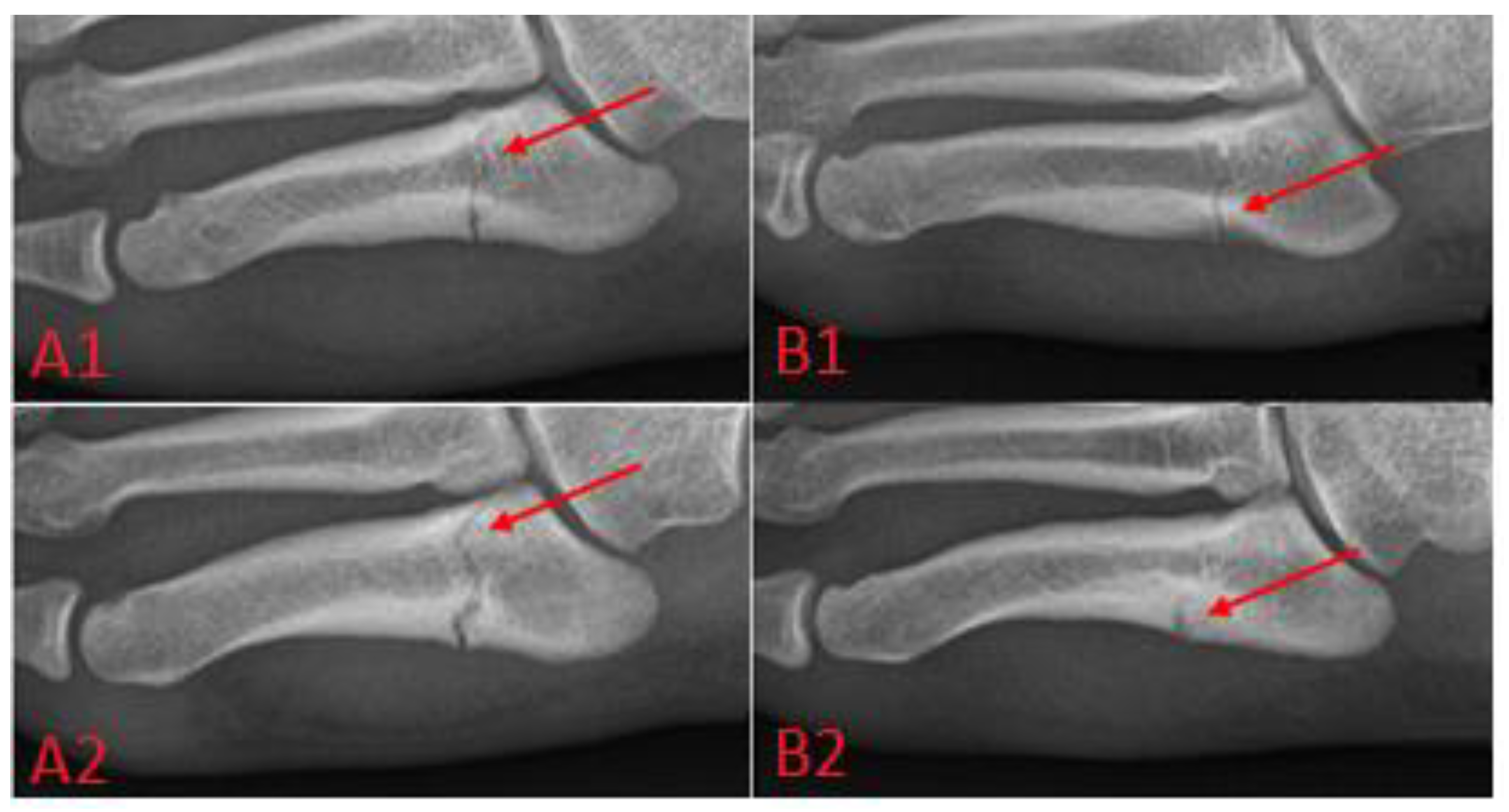
Metatarsal fractures, see
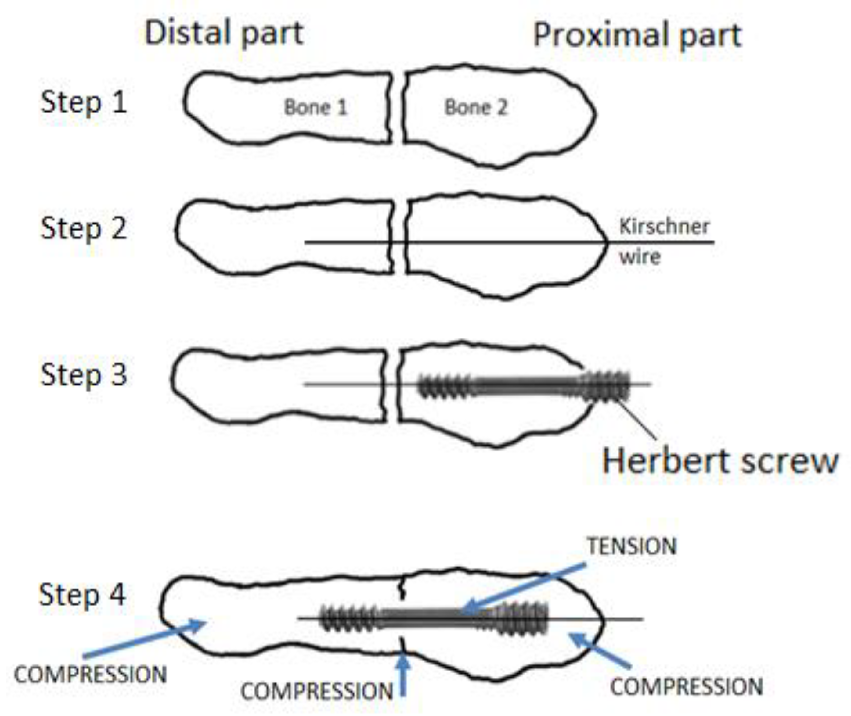
Figure 3, can be treated surgically or conservatively; this paper focuses on the headless screw technique, in which the fracture is immobilized by the screw thanks to the differential pitch of the threads at the threaded ends, which leads to pulling the bone fragments together and, subsequently, to healing.
The application of the headless screw is shown graphically in
Figure 4. The procedure of osteosynthetic treatment of the fifth metatarsal fracture is described in more detail in [
3]. It is divided into several steps. A Jones fracture and a fatigue fracture are priori fractures without displacement, so in principle, it is not necessary to perform reposition. However, at the beginning of the surgery it is necessary to check whether displacement has occurred using an X-ray intensifier. Then, a (Kirschner) guide wire is drilled into the bone fragments and used to guide the implementation of the cannulated headless screw. The headless crew is introduced into the bone fragments to ensure that the bone fragments are connected in the correct position; see
Figure 4. The correct length of the screw is detected using a drill. It is important that there is compression, that the screw is not too long, and that it is fully immersed in the bone. The resulting position, compression ratio, and length of the screw is checked with an X-ray intensifier in the operating room. The procedure is minimally invasive, and it is performed through a minimal incision of approximately 10 mm. After the procedure, a leg bandage is applied, and rigid fixation is not necessary. The load is recommended according to tolerance.
Frequent complications of surgical treatment of fractures of the fifth metatarsal are the failure of osteosynthesis, accompanied by necrosis of the surrounding tissue, nonunion, irritation of soft tissues, or chronic pain. Less commonly, osteosynthesis is accompanied by pseudoarthrosis, infectious complications, or thrombosis.
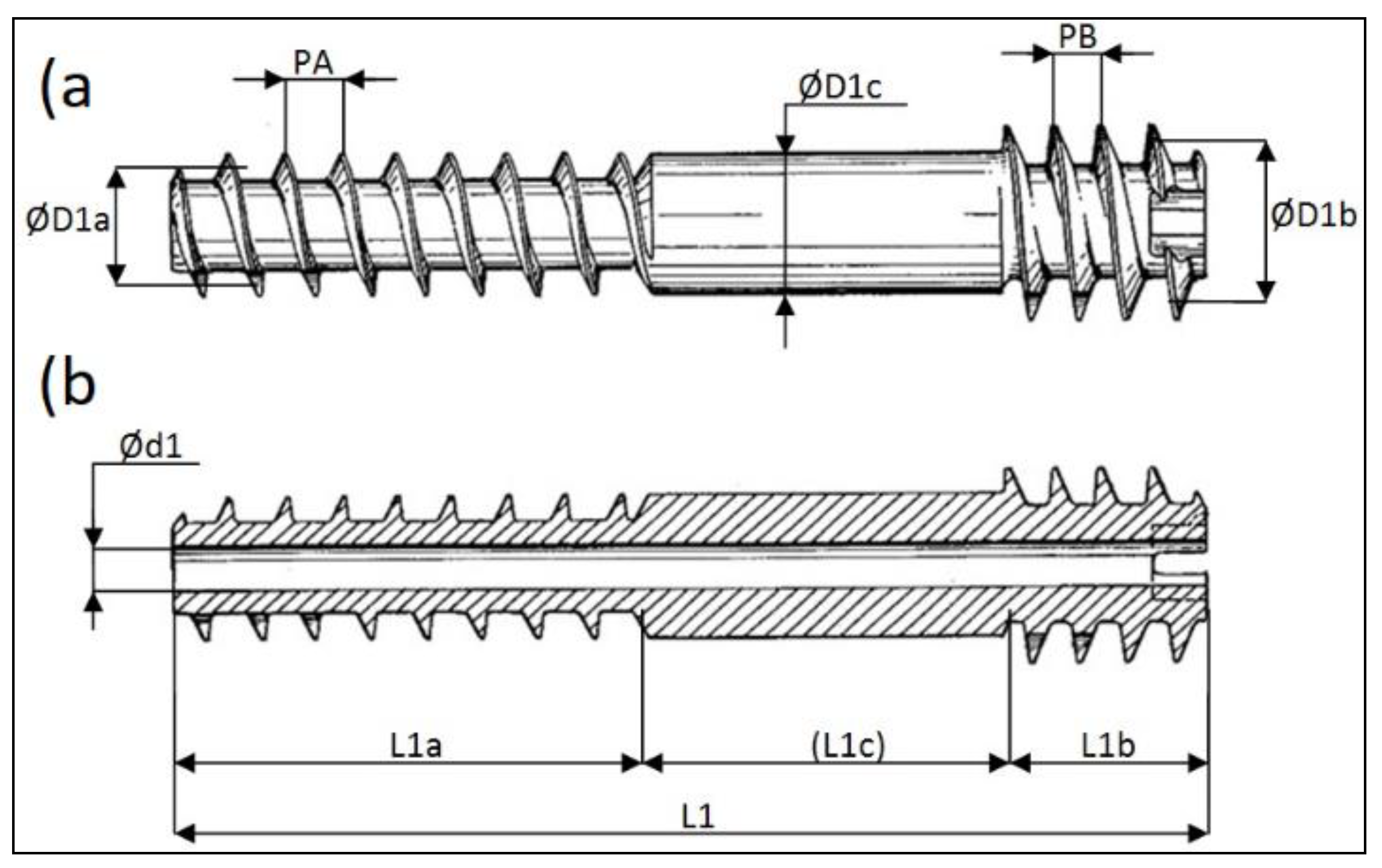
This paper is particularly focusing on the headless cannulated Herbert screw Ti: 4.0/1.4 × 30/7 produced by the Czech company MEDIN a.s.; see [
14]. This screw is depicted in
Figure 5, and its basic dimensions are shown in
Table 1. The diameters ØD1a [mm] and ØD1b [mm] are the median diameters of the resective threads.
In this paper, strength and stiffness analysis of a headless screw is carried out using analytical, stochastic, and experimental approaches. The study focuses on osteosynthesis of the fifth metatarsal fractures, but the results can be used for other applications in trauma and orthopedics too. An original analytical design was devised, and an experiment was performed, in which the normal axial compressive forces acting on a headless screw during the osteosynthesis of porcine bones under laboratory conditions were measured and evaluated. The finite element method was also used to a minor degree. The information provided in this study fills the gaps in the knowledge of the biomechanical information of headless screws and serves as a basis for clinical applications for further improving patient care and new designs of headless screws.
2. Analytical Approach
In the analytical approach, mathematical equations required for the analytical calculation of the maximum stress in the headless screw and fragments of the fractured fifth metatarsal are defined. Mathcad software was used for the actual analysis [
15]. The acquired results originated from constant input values, and our analytical approach was, therefore, a deterministic approach. The follow-up stochastic (probabilistic) approach is discussed in
Section 3.
Only small deformations were assumed, inferring the validity of Hooke’s law. In this calculation, the material was considered homogeneous and isotropic, which is a standard and widely used simplification of the generally very complicated reality. These simplifications are acceptable and typical in common engineering tasks.
The mutual closeness of fragments is a necessary condition for correct osteosynthesis. The drawing of fragments together is mediated by the different pitches of the ends of the headless screw. For this, the thread pitch PA [mm] must be greater than that of
[mm] (i.e.,
); see
Figure 5. If the bone fragments are close enough and the headless screw is implemented, the axial shifting (displacement) of the bone fragments Δ depends on the number of rotations of the headless screw (n) [
1] and is defined as
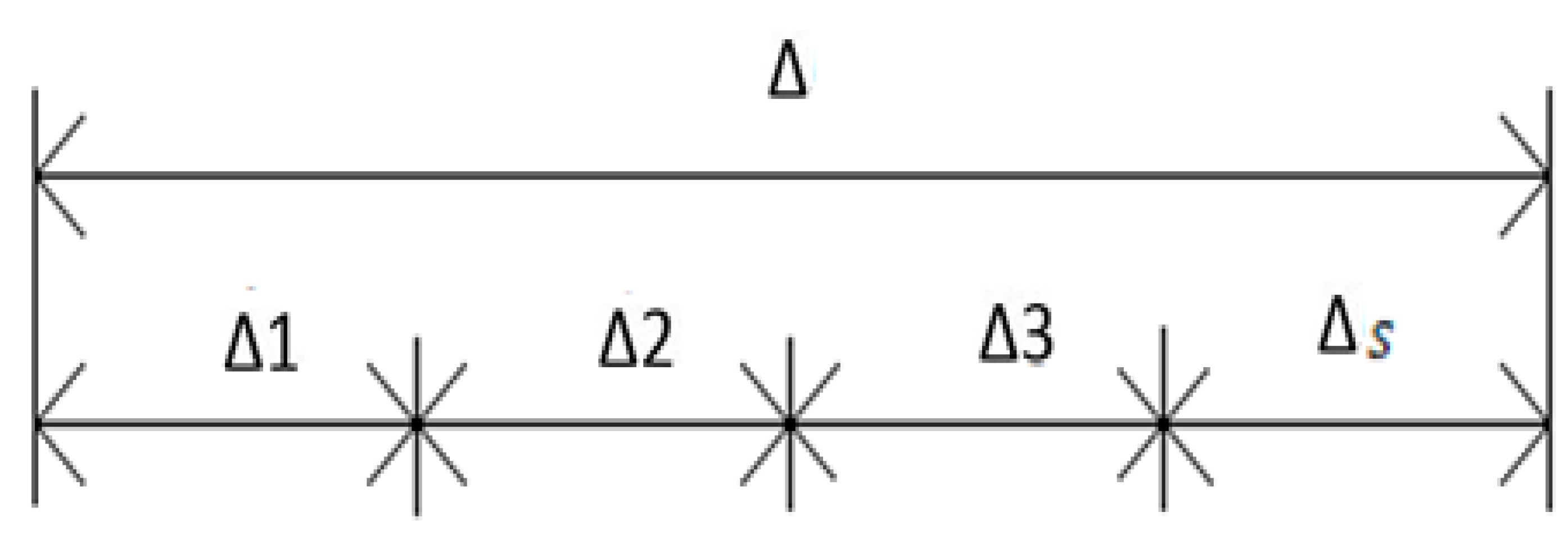
The displacement causes compression and preload in the headless screw. The displacement Δ is shown in
Figure 6 as the required deformation condition (a special type of boundary condition in mechanics).
Explanation of displacements in headless screw and bone fragments are shown in
Figure 7.
A sensor (i.e., axial force and displacement gauge) was also considered in the analytical solution to allow comparison with the experiments performed in
Section 4.
This task was solved as an interesting elasticity problem because it was a statically indeterminate task of the first degree in tension and compression. It was, therefore, necessary to determine the deformation condition. The deformation condition describes the relationship between the screw elongation (Δ1 [mm]) and bone fragment shortening (Δ2 [mm] and Δ3 [mm]); see
Figure 6 and
Figure 7 and Equation (2). To derive Equation (2), the basic relationships of mechanics were used; namely, we used Hooke’s law, the relationship for axial tension/compression stress, and the relationship for relative longitudinal strain under tension/compression. Hence,
The internal normal force
is therefore described as:
with the meaning of individual variables given in
Table 2.
This calculation and way of derivation is exposed in more detail in [
16]. The above-described analytical approach was also used to establish the equations of the stochastic approach (application of the Monte Carlo method), explained in the following section. The measurements are described in more detail in
Section 4 of this paper. The value of the tensile modulus of the bone was adopted from [
17].
3. Stochastic Approach
The probabilistic calculation was performed in the Anthill software, in which the analysis was performed using the SBRA (simulation-based reliability assessment) method. The SBRA method applies the probability theory and statistics to stochastic inputs. The output variables affecting the safety of a structure or machined part are usually expressed as truncated histograms. Due to the random nature of the input variables, the resulting output variables also possess a random character. This allows a probabilistic assessment of the engineering problem [
18,
19].
The method is based on the direct Monte Carlo approach, which analyzes the reliability function using sequences of pseudo-random simulations (realizations). The simulation works with a large number of pseudo-random samples (in our case, 10
6 random simulations), and the input and output values are defined using bounded histograms [
18,
19,
20,
21].
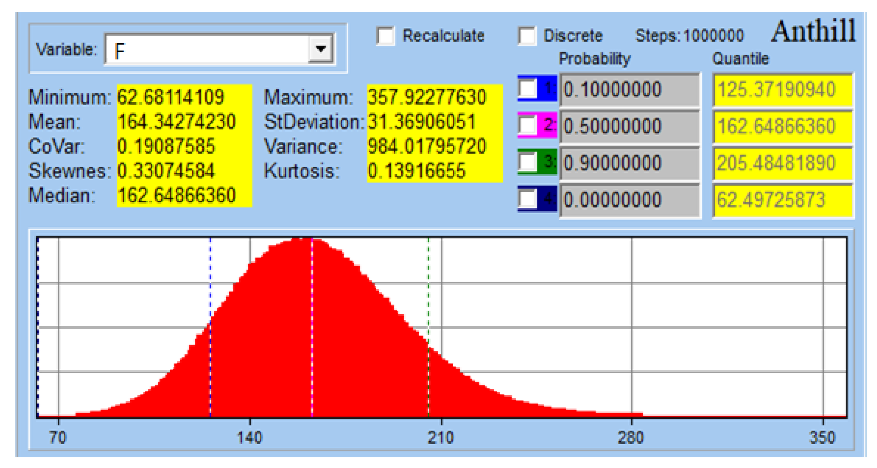
In our calculation, input stochastic variables used screw and bone dimensions and their mechanical properties. Thanks to this, possible inaccuracies in production, different bone anatomy, and their mechanical properties could be included in the calculation. Output variables were axial normal force, maximal stress in the screw, and reliability function.
Figure 8 shows histogram of the axial normal force.
Reliability function
is defined as
where
is the yield stress of a screw and
is the maximal stress in the screw.
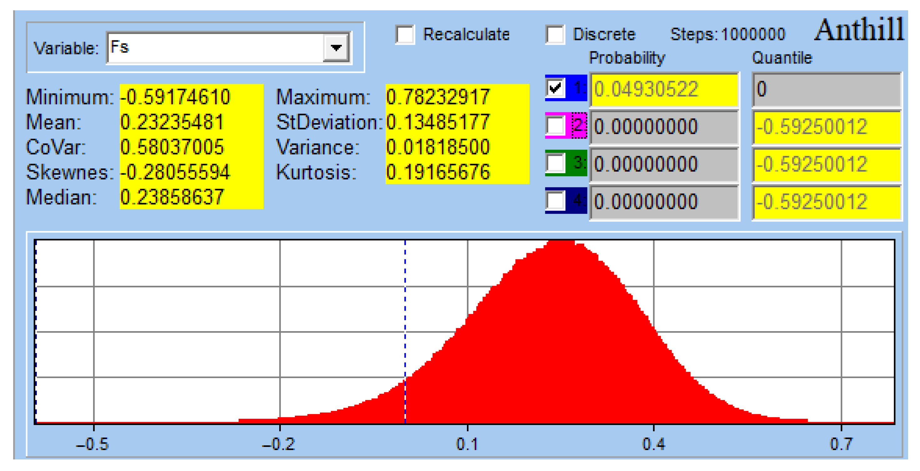
The situation where
≤ 0 expresses the probability of a condition where the thread cut in the bone fragment is sheared. The calculated reliability function
is shown in
Figure 9. Thread shearing and thus, plastic deformation, occurred in the bone with a probability of only 0.0493 (i.e., of 4.93%). If thread is sheared during surgery, the headless screw can be replaced with a larger diameter headless screw, and the surgical procedure can subsequently be completed, which further reduces the risk to the patient.
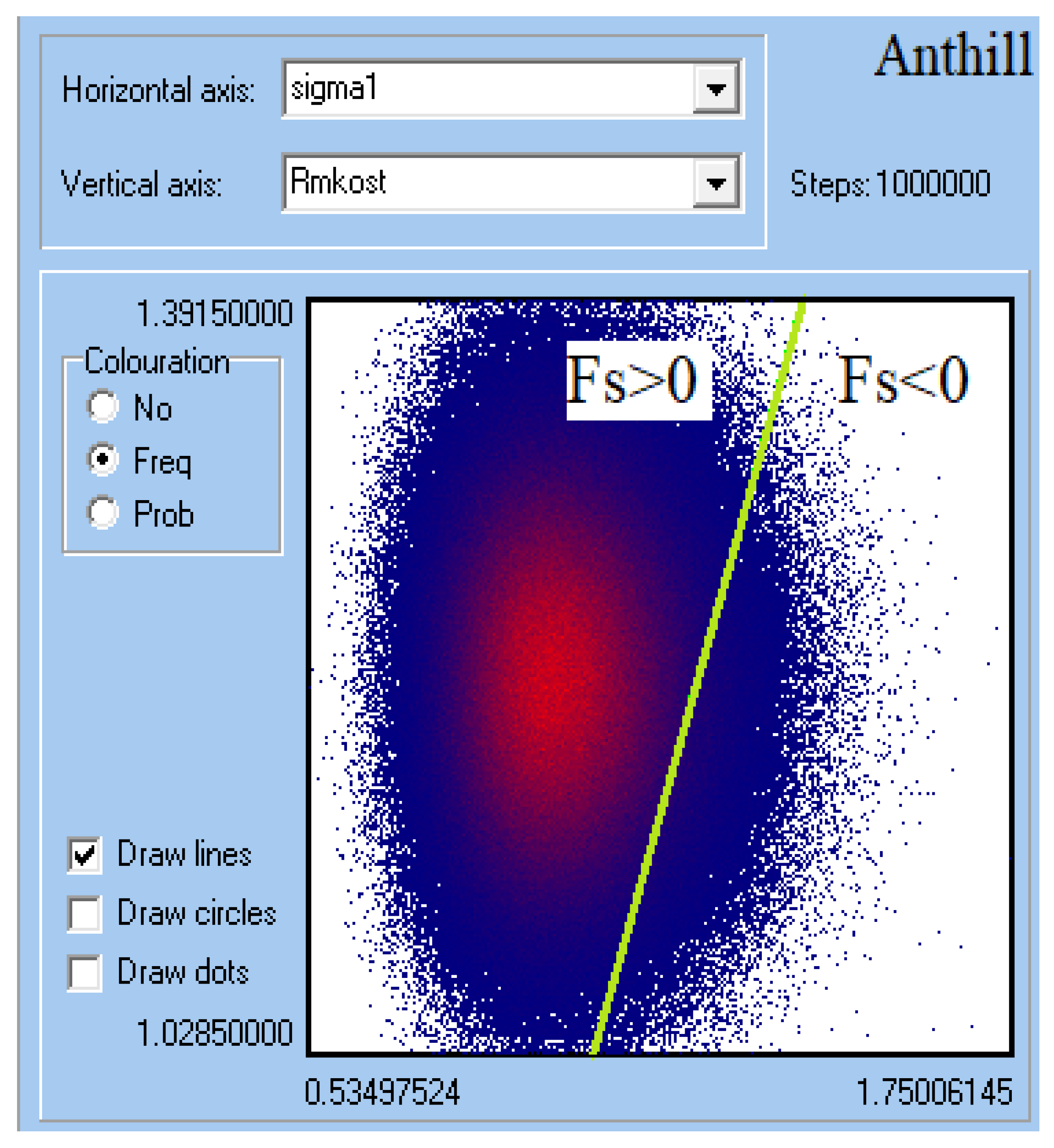
Figure 10 shows the 2D distribution of the reliability function
. Towards the center, the frequency of the reliability function values increased, with higher frequencies of occurrence shown in red. The green color indicates the limit line, which divides the reliability function into negative and positive parts. If the reliability function is negative (i.e., Fs < 0), the headless screw is in the region of permanent plastic deformation and thread shearing will occur. Conversely, if the reliability function is positive, it is in the region of elastic deformations, and no limit state causing thread shearing in the bone can occur.
4. Experimental Section
The experiment aimed to obtain information about the dependency between the tightening of the headless screw and to determine the normal force acting on the headless, self-tapping cannulated screw (same as in the calculation, i.e., Ti: 4.0/1.4 × 30/7 mm by MEDIN a.s.; see
Figure 5 and
Table 1). The acquired results can then be compared with analytical, numerical, and stochastic calculations.
The knowledge of axial forces acting during osteosynthesis is important when designing headless screws and their threads. In real-life fractures, bending stress is also present, but compression and tension are the dominant stresses on the bone fragments and screw during screw introduction (insertion). Moreover, this type of information is missing in literatures. The experiment was performed on a headless screw introduced into porcine leg bones purchased from a conventional butcher shop. The porcine bones are commonly used as a readily available substitute for human bones, including metatarsals [
22]. The use of porcine bones was in accordance with ethical standards and did not require approval from an ethics committee.
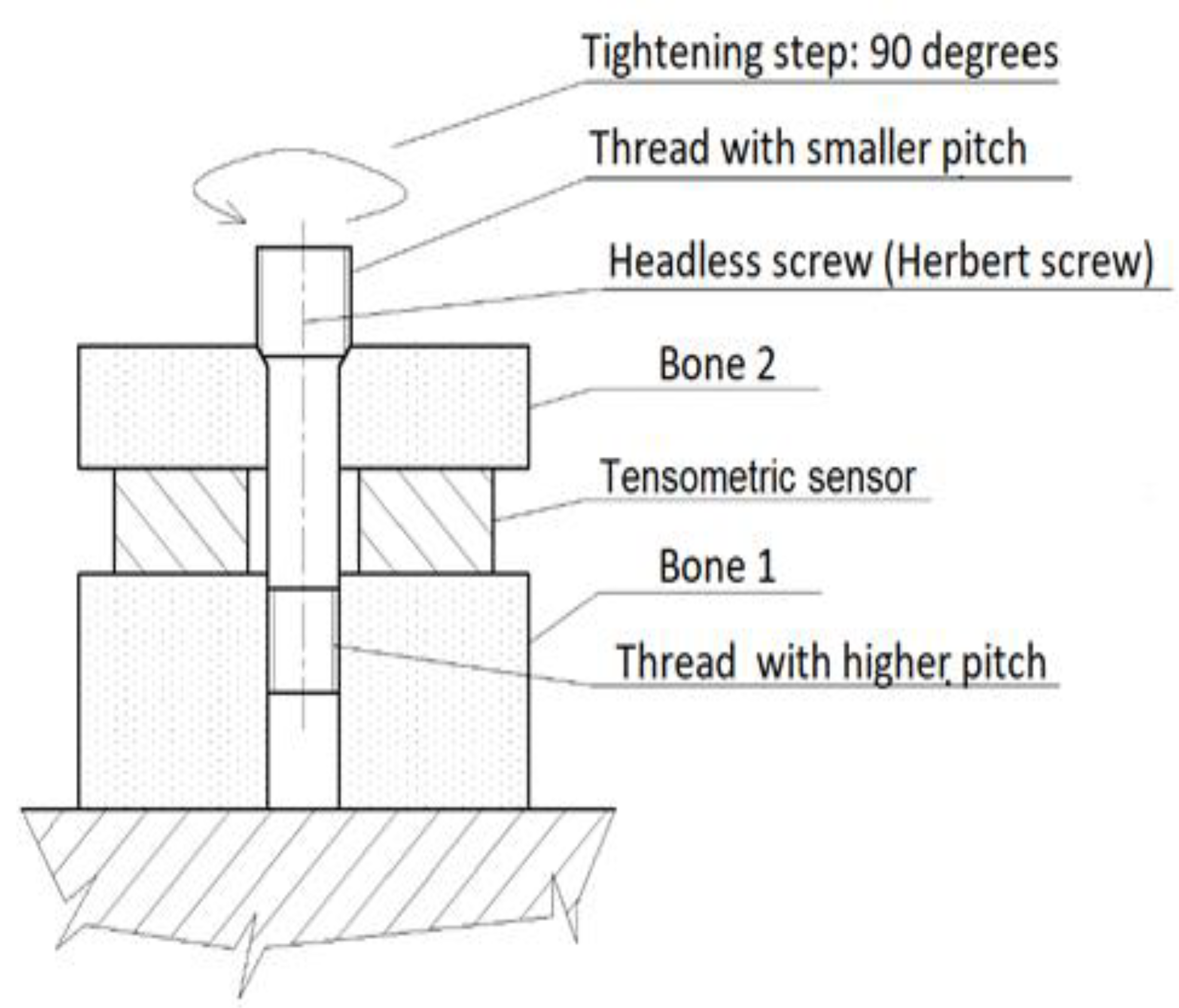
Tightening the screw inside the bone fragments elicited a compressive force measured by a holed strain gauge transducer. First, the porcine bone fragments were pre-drilled, then a tensometric sensor (LC 8150-375-500, Tensometric Messtechnik GmbH, Wuppertal, Germany) was placed between the bone fragments, and a headless screw was inserted. In accordance with the operating procedures, the headless screw was tightened to a tightening torque of 2.5 Nm. This value was experimentally verified by previous measurements to ensure that the screw threads were not stripped while driving the screw into the examined bone fragments. The force was measured in quarter-turn increments, i.e., 90°, until the headless screw was tightened to 3.5 turns; this also included the moment of the thread shear (i.e., the maximum moment) in the bone. (Thread shear will cause the osteosynthesis to fail but will not destroy the implant.) The principle of the measurement is shown schematically in
Figure 11.
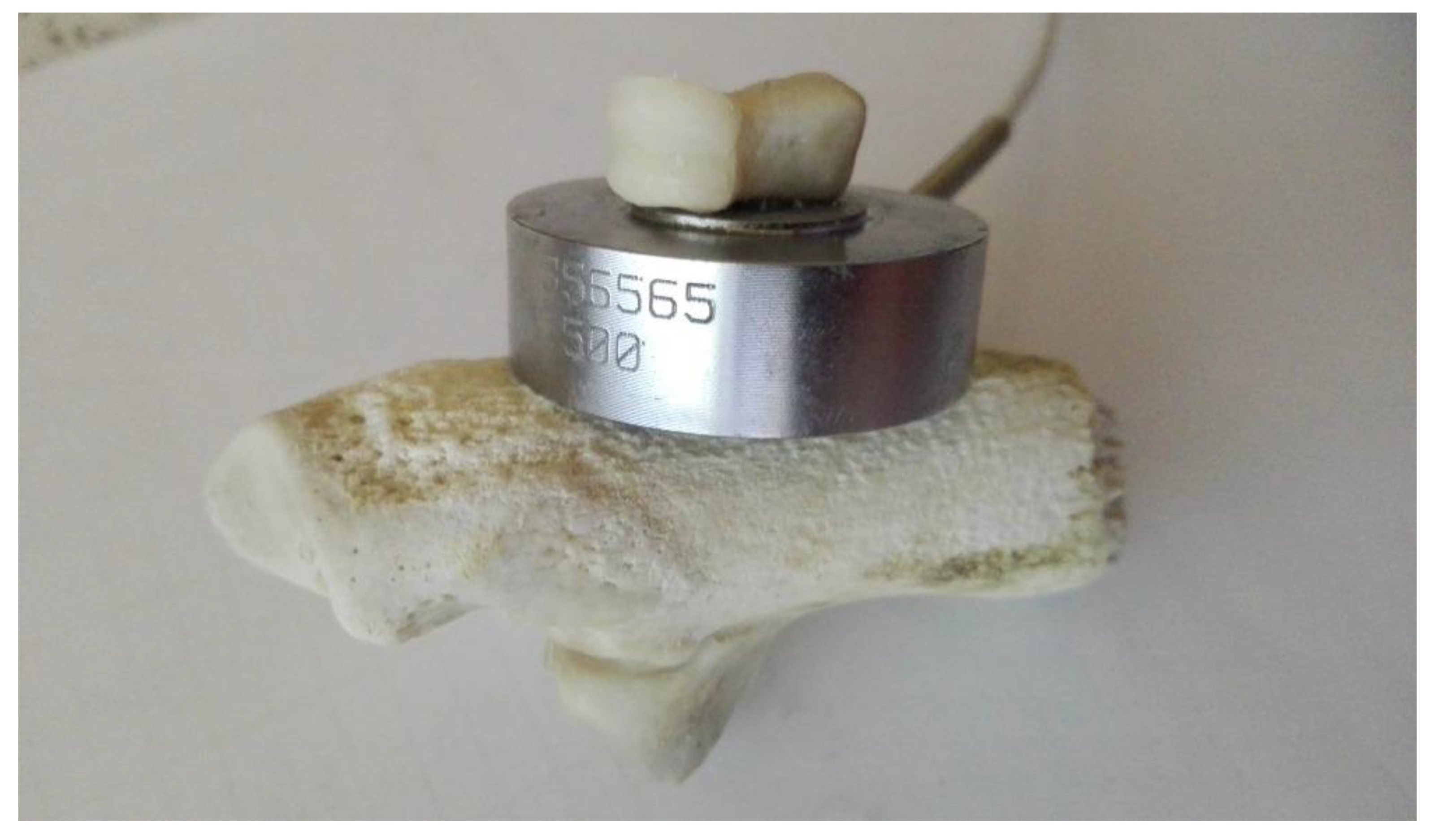
Figure 12 shows the real measurement of the compressive axial force acting on the headless screw. It depicts two fragments of a cleaned pork bone, joined with a screw, and a holed compression force sensor inserted between them.
The investigated screw was made of titanium alloy Ti6Al4V, the properties of which are specified by ISO 5832-3 (material for surgical implants). This alloy, together with the stainless steel 316L, are two of the most commonly used materials for the manufacture of implants [
23]. The screw material was considered biocompatible, isotropic, and homogeneous, and its basic mechanical properties are shown in
Table 3. The screws were manufactured by conventional machining methods.
The measurements took place at the laboratory at the VSB—Technical University of Ostrava, Faculty of Mechanical Engineering, Department of Applied Mechanics (Ostrava, Czech Republic).
In all, 10 measurements were performed.
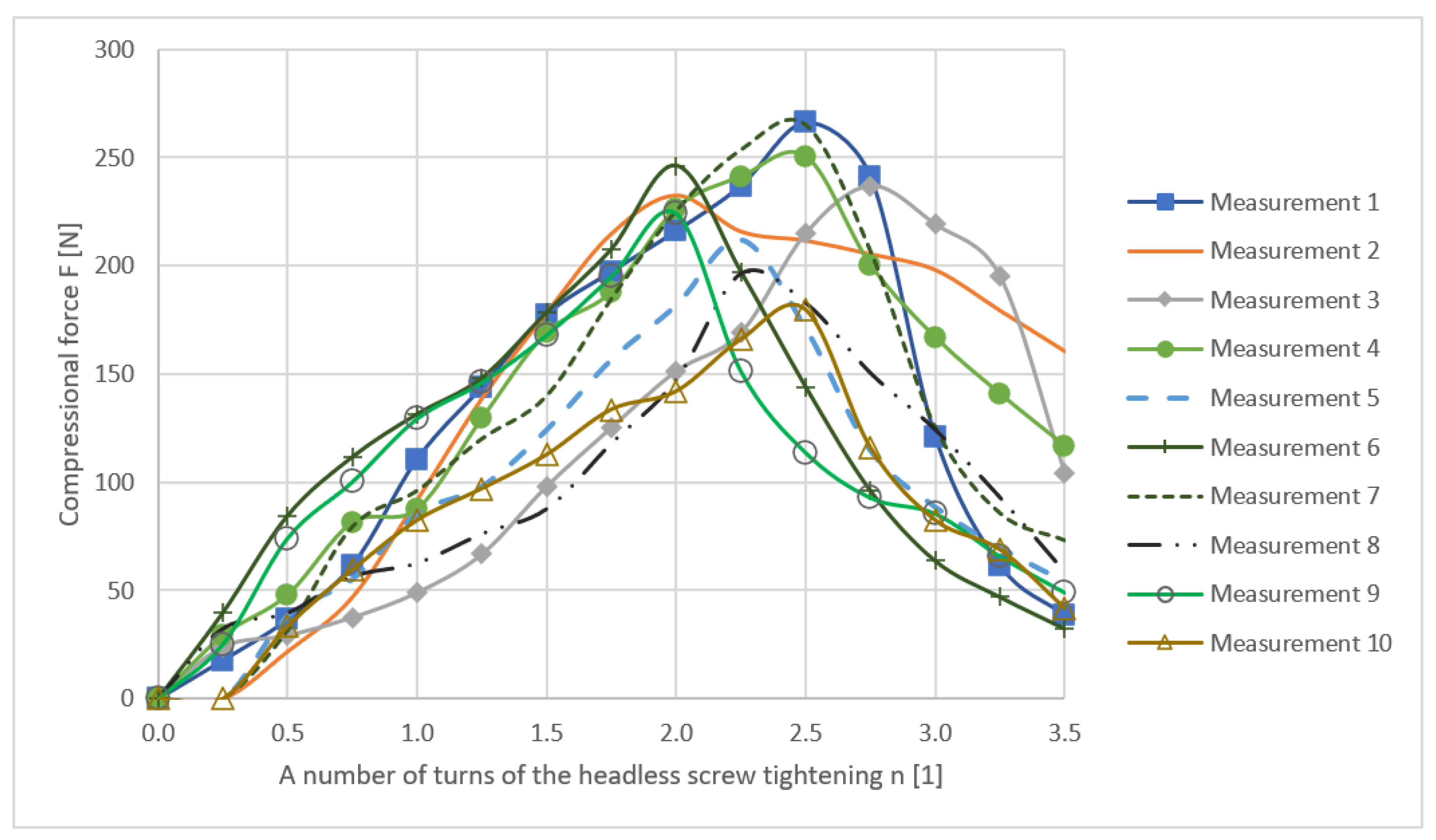
Figure 13 shows the dependence of the axial compressive force F on the number of turns n (in quarter-turns) of the headless bolt.
Table 4 shows the maximum force F, number of turns for each measurement, and the values of arithmetic mean, median, and standard deviation.
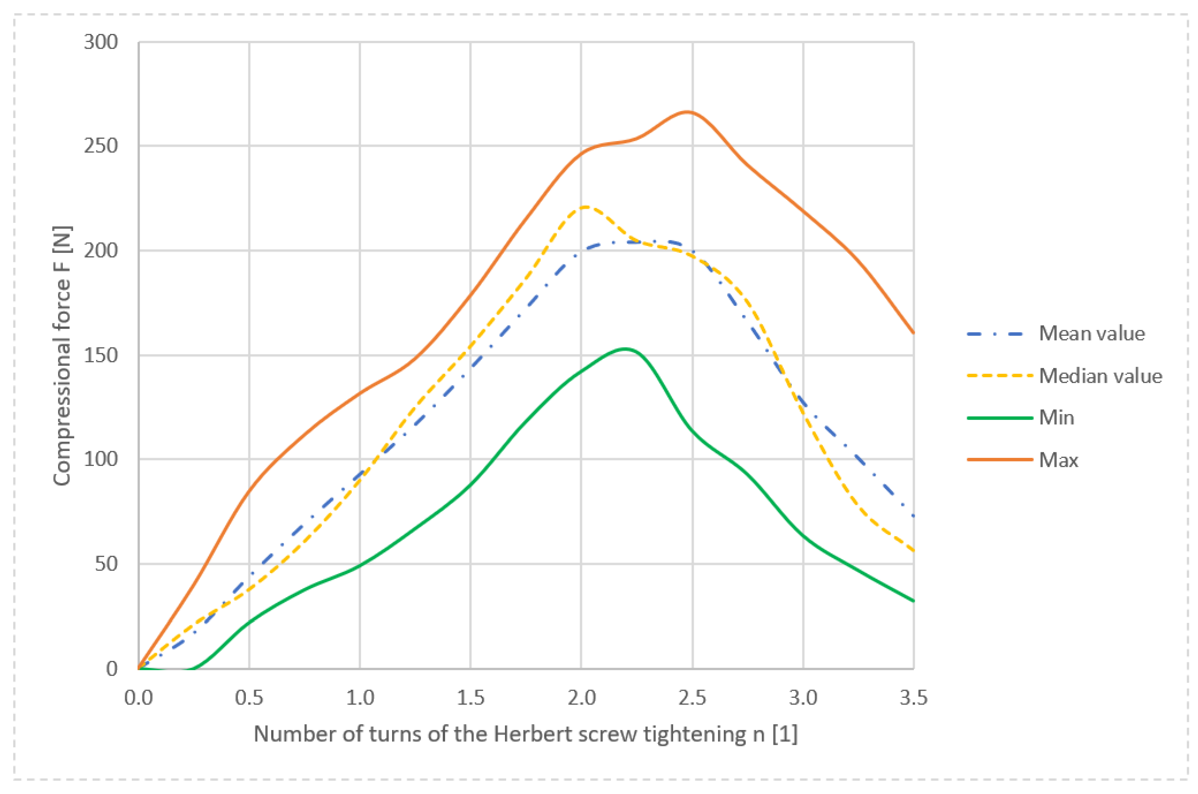
After 2–2.5 turns, the curves reached their maximum, at which point the Herbert screw thread in the bone failed (bone damage), and the compressive force started to decline. The maximum force was reached in measurement 1—tightening to 2.5 turns generated a compressive axial force of 266 N. The region from 1.75 to 3 turns of the screw can be perceived as a risk area of 180 to 266 N. Exceeding the strength limit of the bone fragment led to the plastic deformation in the area of the thread cut in the bone and the thread was sheared.
Once the thread in the bone was sheared, a sharp decline in the force was expected. This was not confirmed, which can be explained by the existence of frictional forces observed on the contact surfaces between the bone and the screw and by the development of elastoplasticity in the area of interest.
The statistical evaluation of the results is shown in
Figure 14. The maximum average compression force was 230.9 N and acted on the screw at 2.25 turns; after that, the thread in the bone was sheared off, and the compression force began to decrease. The highest median value of the normal compressive force (220 N) acted on the screw at 2 tightening turns. The maximum and minimum measured values of the force F formed the envelope of the course of the compressive force dependence.
We also looked for a function suitably approximating the measured data, as finding such an approximation function is advantageous for their further processing. The experimental data obtained in our experiment showed similar behavior of the compressional force as the data obtained when measuring the dependence of the force on the screw displacement when the screw was being pulled out of the bone [
24], which studied the effect of elastic foundation on tearing a screw out of the bone. Based on the similarity between data reported in [
24] and our findings, we can conclude that the compression forces are also influenced by elastic foundation in the case of Herbert screws. More information about the elastic foundation can be found in [
21,
24].
Hence, the search for an approximation function was based on the findings in that previous study and used a similar mathematical model. The measured data were approximated by a cosine power function , where , , and are constants. which interpolated the values very well.
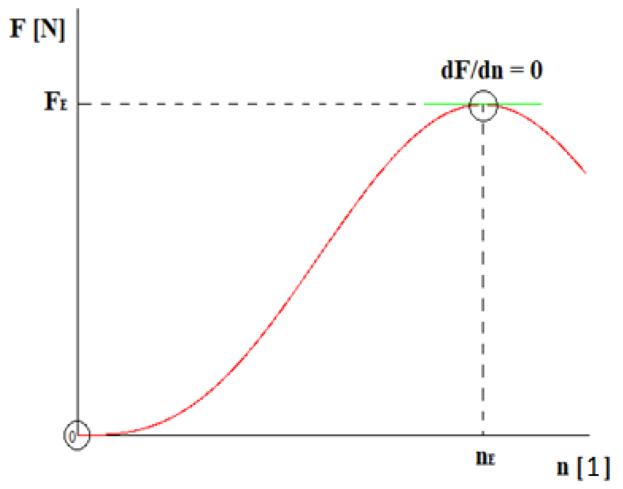
The approximation function must satisfy the following boundary conditions:
Mentioned boundary conditions are shown in
Figure 15.
After the introduction of boundary conditions, the solution for the following equation was calculated:
From Equation (5), it is clear that only the parameter
m was unknown. This parameter can be found by regression, for example, using the Matlab software, version R 2019b (Toolbox Curve Fitting), created by The MathWorks, Inc. (Natick, MA, USA) [
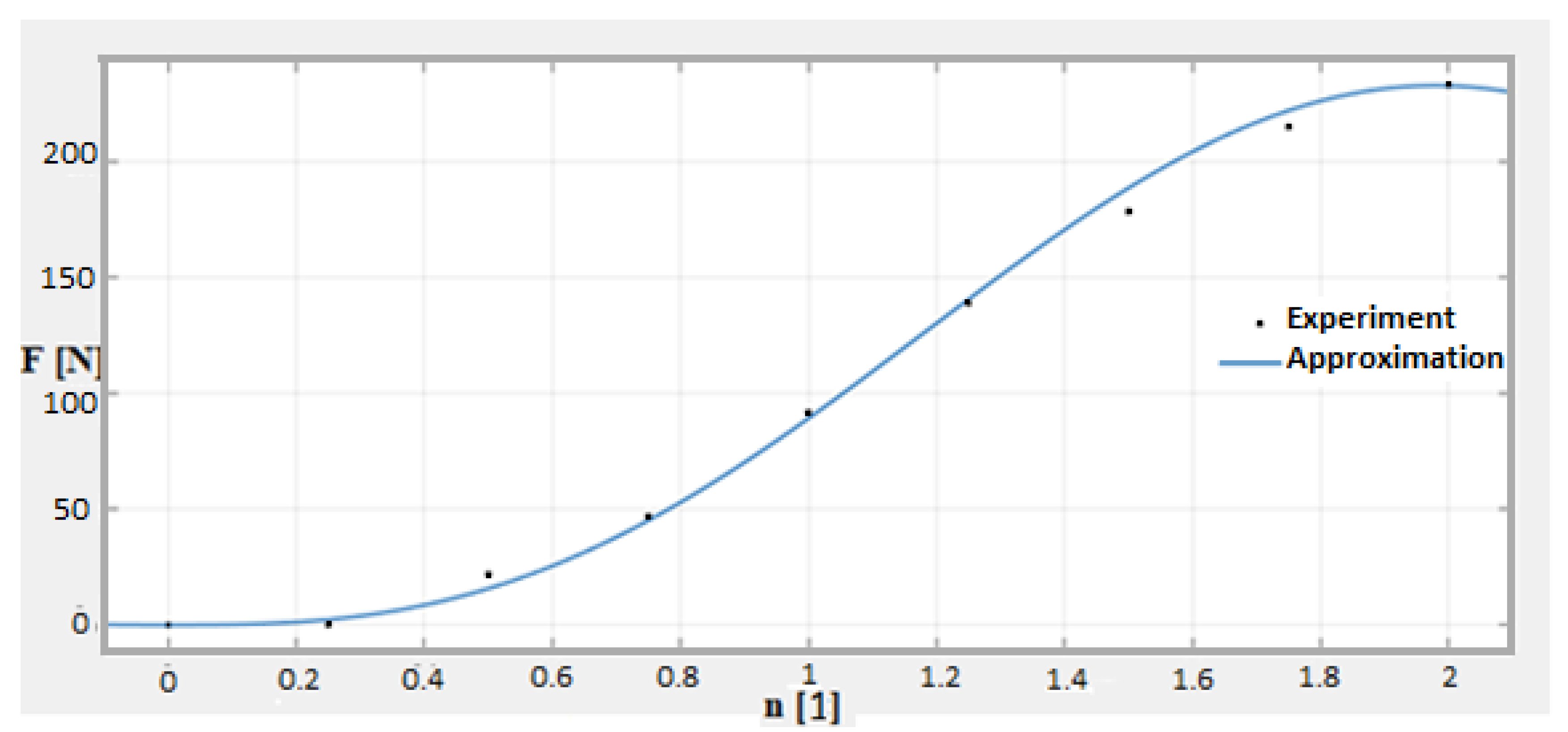
25]. Values from all measurements were interpolated using this function. For clarity,
Figure 16 shows the interpolation of the experimentally measured points (from measurement number 2) by the calculated approximation curve.
The coefficient of determination R
2 was evaluated for each approximation curve. As known from statistics, this coefficient determines the quality of the regression model. The values of the coefficient of determination were in the interval <0; 1>, where 1 means an ideal prediction of values, and 0 means that the values are independent. If the determination coefficient is greater than 0.9, the result is considered very good.
Table 5 shows the required parameters for all measurements.
The approximation always coincides perfectly in the vicinity of the point [nE, FE], which represents the limit state, and therefore, its accurate capture and description are of utmost importance.
5. Comparison of Results
Results obtained analytically (deterministic—
Section 2 and stochastic—
Section 3—solution) and experimentally (
Section 4) were compared.
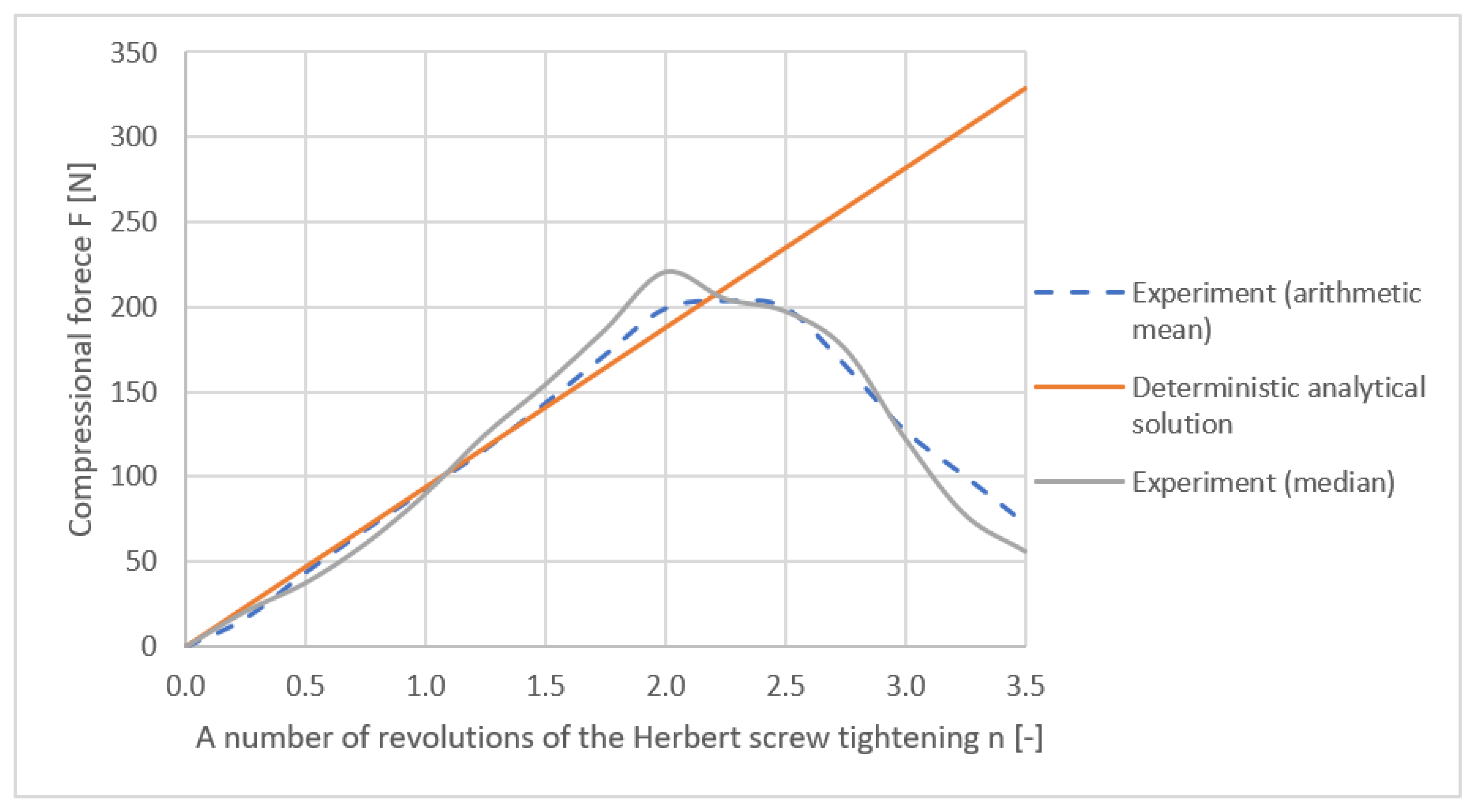
The comparison of the analytically calculated and measured axial force is shown in
Figure 17. From the graph, it is evident that in the linear elastic region of up to 1.75 turns of the Herbert screw, where the thread is not sheared, the agreement between the analytical solution and measurement is very good. For this reason, the probabilistic solution is also performed for this number of turns.
6. Results and Discussion
Several modifications and extensions can be made in the future to further develop this work. Additional measurements can be made to determine the torque and frictional forces applied when screwing the Herbert screw into the bone. Performing measurements on other types of screws would also be interesting. Herbert headless screws can vary in size or in the thread pitch; there are also screws with variable thread pitches [
14].
In this work, solely porcine bones were used for the experiments. Further study could focus on the modification of the experiment in the sense of using human cadaverous metatarsal or even other bones; this is, however, ethically more problematic and costly. Bones from other animals (e.g., bovine, calf, mutton, etc.), as well as artificial composite bones (e.g., products by Sawbones) or wooden bones, could be used for the experimental solution.
Performing an experiment focusing on other ways of loading the screw (such as bending or fatigue testing) could also be interesting. The effect of bending or major deformations (true stress or logarithmic strain) or elastic/non-linear foundation could also be introduced in the experiments, as well as computational solutions. This is likely to lead to an improvement in accuracy, but the nonlinear solution will be much more complicated, and the advantage of the original simple linear solution will be lost.
We can also build on our extensive experience in the field of interaction between external/internal fixators with bones [
26,
27,
28] (finite element method, deterministic approaches, stochastic approaches, and experiments).
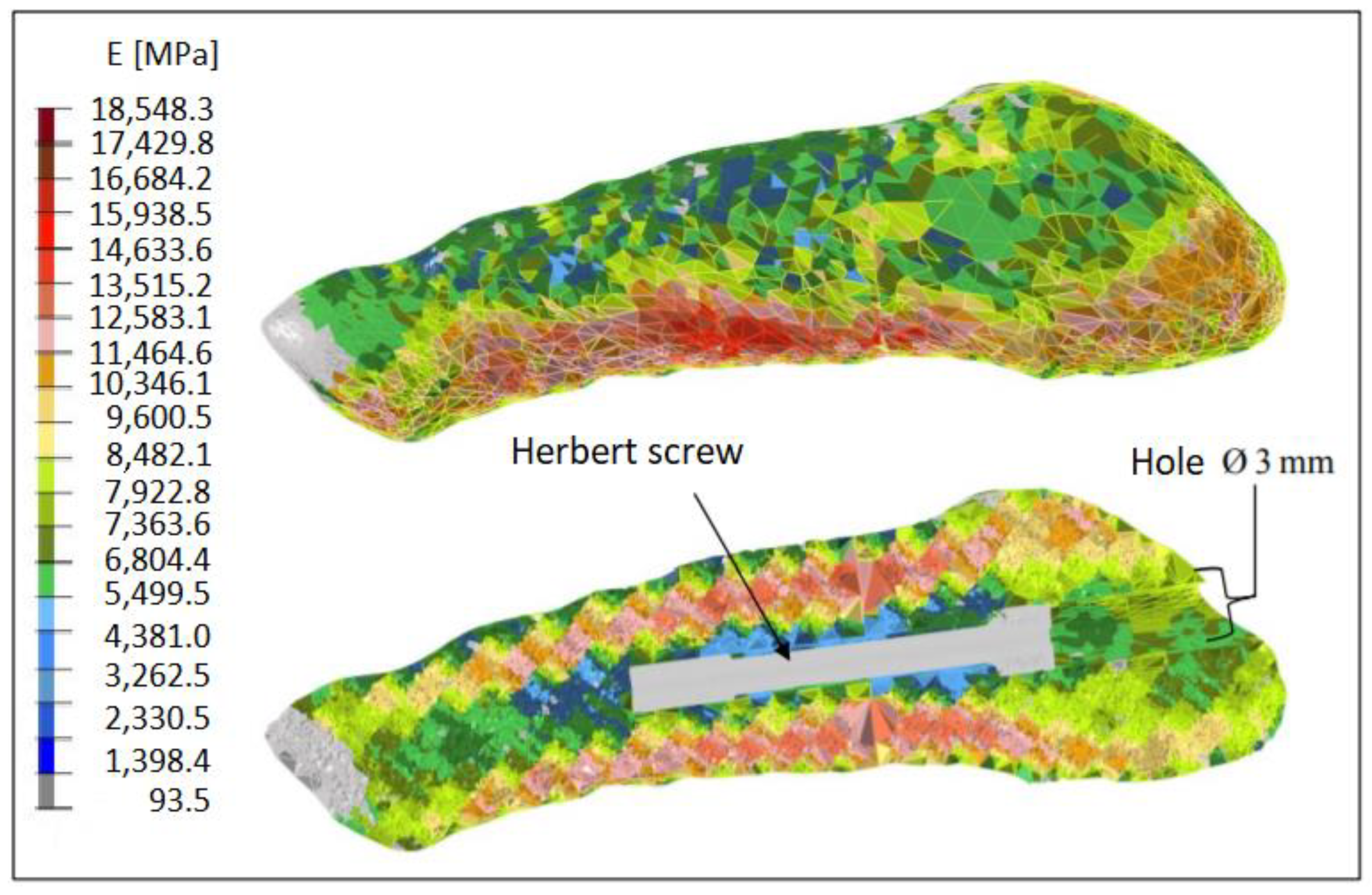
Aside from that, we can use the finite elements method (FEM) for comparing the results. Using the Mimics software, X-rays (i.e., computed tomography) of the bones can be used for creating a CAD and finite element model of the fifth metatarsal and assigning material properties to its individual parts.
Figure 18 shows a distribution of the elasticity modulus in the fifth metatarsal, ranging from 93.5 to 18548.3 MPa [
29].
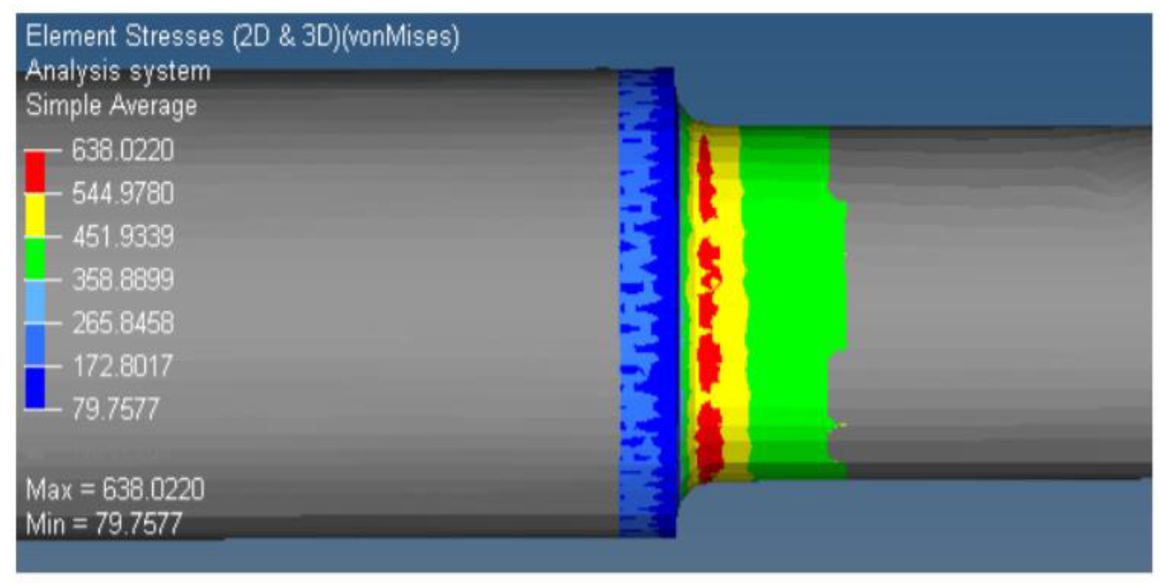
According to [
29], simulation revealed that the critical equivalent von Mises stress can be detected at the notch of the screw; see
Figure 19 and
Figure 20.
The calculation using the FEM method gives results similar to the solutions presented in this paper; nevertheless, it is not the main focus of this publication, just complementary information. A deeper look at the FEM solution, which is more complex and more difficult to relate to stochastic approaches, will be a subject of future publications. However, the author team feels that it is appropriate to mention the FEM method here, as well as the fact that FEM calculations have confirmed the facts obtained from other computational approaches and experiments performed in this study.
7. Conclusions
The main objective of this study was to perform stress–strain computational analyses and an experimental analysis for the determination of the axial force generated during osteosynthesis with a headless Herbert screw (Ti: 4.0/1.4 × 30/7 mm, Medin a.s., Czech Republic). This screw is intended for the osteosynthesis of fragments of the fifth metatarsal fracture. Such implants are commonly used in medical practice. Due to the different pitches of the threads on both ends of the screw, the bone fragments are drawn to each other and compressed at the fracture site, which facilitates the process of fracture healing.
The analytical (deterministic) calculation was defined as a tension–compression problem. This problem was statically indeterminate to the first degree, which required the use of an additional deformation boundary condition.
The relationships derived from the analytical calculation were used for the stochastic (probabilistic) approach, which, through pseudo-random values generation from defined histograms, allows us to respect the real variability of the input and output data and to perform a probabilistic reliability assessment. Here, the Monte Carlo method was used for the solution and evaluation of 106 pseudo-random simulations.
In addition, an experiment (10 measurements) aimed at determining the compressive normal forces acting on the Herbert screw during tightening was performed. This experiment revealed the average force required to shear the thread in the bone to be 204 N. This is an important finding for headless screw designers and for surgeons developing new surgical techniques.
Next, a suitable function sufficiently approximating the measured values from the experiments was searched for. The excellent quality of the fit of the regression model to the experimental data was demonstrated using the coefficient of determination R2.
Finally, the results of all approaches were compared. As the approximation of the experiment using a cosine power function () is suitable and provided sufficient accuracy, it is obvious that the task can be solved analytically as a second-order differential equation, which subsequently leads to a significantly simpler and computationally less demanding solution than the use of the FEM approaches. Our model also enables a relatively simple application of the probabilistic approach, which is advantageous, as it allows respecting the real variability of input and output variables, which is typical of the real world.
This paper also briefly mentions the numerical solution based on FEM.
The results of all four approaches to the solution (i.e., deterministic, stochastic, experimental, and numerical) are in sufficient agreement and confirm the suitability of the examined screw for clinical use.
This combined algorithm can be used as a basis for implant certification or recommendations for clinical testing of various types/applications of headless Herbert screws in medical or veterinary practice, as well as for the modification or change of screw design.
The acquired data on axial forces in osteosynthesis of the fifth metatarsal were determined in an original and novel way in this study. From this perspective, the paper significantly contributes to the field of fracture biomechanics.
The applications and conclusions obtained in this paper can be used in other fields as well—even in the construction industry in the analysis of joints in wooden structures [
24,
30,
31].
