Abstract
While dismantling nuclear power plants, the reactor vessel internal is cut underwater using mechanical and thermal cutting. In laser thermal cutting, assist gas must be used to remove melted metal; consequently, a large number of radioactive aerosols can be generated. To reduce the generation of aerosols, the assist gas pressure should be lowered. However, below the pressure limit, the molten metal is not well-removed from the cut surface and fails to cut. In this study, an assist gas visualization experiment was performed to find a condition for the gas to flow well inside the cut surface, even at low pressures. The top kerf width, nozzle type, distance between nozzle and specimen, and assist gas pressure were selected as process parameters, and in the case of large top kerf width condition, assist gas was able to penetrate deeply. In the actual laser-cutting experiment, the laser beam focus position was set to −20 mm and −30 mm. In the case of −30 mm, the top kerf width was widened due to the characteristics of the laser beam profile, and cutting was successful even though the assist gas pressure was lowered by 20%.
1. Introduction
The nuclear-power-plant-decommissioning procedure is mostly completed in five steps: removing fuel rods, decontaminating and cutting the system components, dismantling the reactor, treating waste, and restoring the soil. To dismantle reactor vessel internals (RVIs), they should be cut into pieces underwater, put in a basket, and pulled out of the water pool [1]. Mechanical-cutting and thermal-cutting methods are mainly used to dismantle RVIs and their components. Mechanical cutting includes disk saws, band saws, abrasive wheels, diamond-wire cutting, and shears. Thermal-cutting techniques include plasma arc, oxy-fuel, and gouging [1]. Recently, the thermal-cutting process that uses lasers as a heat source has been studied [2,3,4,5,6]. Due to its narrow-cut kerf-width characteristic, laser cutting has the merit of reducing the generation of secondary radioactive waste. In most thermal-cutting applications, the high-density heat which is induced melts materials while the assist gas removes molten materials. However, when cutting RVIs in underwater conditions, a large amount of radioactive aerosol can also be generated due to the use of high-pressure assist gas. During laser cutting, particles of a certain size are trapped in air bubbles and released into the air as they rise above the water’s surface [3,7]. Because of their fine size, the aerosols generated by thermal cutting are not only difficult to handle in the nuclear power dismantling process, but additional aerosol-collecting equipment must be used to protect workers from radiation exposure [8]. The plasma-cutting process was widely applied until the 1990s, but the total dismantling-process-management cost was increased due to large amounts of fine radioactive particle generation. Mechanical cutting methods have been gradually applied since the 2000s, due to the decrease in the generation of radioactive secondary waste [9,10]. Kim et al. [8] reported cutting speeds and aerosol-generation rates depending on the material thickness and cutting methods used. These data were obtained from the BR-3 nuclear power plant decommissioning project in Belgium. When compare to mechanical cutting, the thermal-cutting method enables high-speed material cutting, but also generates a larger number of aerosols. Furthermore, the thicker the material, the slower the cutting speed and the more aerosols produced [7,8]. The total cost of dismantling nuclear power plants can be reduced by applying a method that generates fewer aerosols while cutting at high speeds. In other words, the cutting speed should be fast and the use of assist gas should be minimized.
Most underwater thermal-cutting studies focus more on the cutting tendency or the success of cutting, and less on reducing the generation of aerosols. To reduce assist gas usage, it is important to understand its flow phenomenon. Several studies on assist gas visualization of cutting nozzles have been conducted [11,12,13]. However, few studies have reported on underwater assist gas flow. It is difficult to observe the state of the process during actual underwater laser cutting. The reason is that, due to the debris and fine particles that are generated during the cutting process, the water becomes dark and cloudy, and it is difficult to accurately capture the assist gas flow pattern. In this study, to reduce the generation of radioactive aerosols during underwater laser cutting, several cutting process parameters are considered, such as the distance between the nozzle and the specimen, the cut kerf width, and the nozzle design. Through the underwater assist gas visualization experiment, the flow of the assist gas was observed and evaluated according to the process parameters. The effects of the process parameters on actual laser-cutting performance were also verified through an underwater cutting experiment.
1.1. Effect of Distance between the Nozzle and the Specimen
In previous underwater laser-cutting studies, the distance between the nozzle and the top surface of the specimen, or the stand-off distance (SOD), was fixed to a specific value. Jain et al. [2] set the SOD value at 1 mm, Khan et al. [3] fixed it at 15 mm, and Leschke et al. [4] used a 1.5 mm SOD value. Shin et al. [5] found that, even though the closer nozzle setting removes the melted metal easily, to prevent the collision of the nozzle and the specimen, SOD was fixed to 10 mm. For the stable laser-cutting process, Choubey et al. [6] were successfully cut the 4~20mm-thick STS304, even with the ±2 mm stand-off distance changes during cutting. Oh et al. [14] changed the stand-off distance from 1 to 4 mm in the process of air laser cutting. At a 4 mm stand-off distance, it failed to cut due to the reduced gas flow momentum and was not able to remove the melted metal. The thickness of RVI components is around 40–50 mm. To cut an RVI underwater while using less assist gas, the SOD should be set as small as possible and maintained during cutting process.
1.2. The Effect of Kerf Width
Tamura et al. [15] used a laser to cut 300 mm of carbon steel and stainless steel in the air. Depending on the assist gas flow rate and top kerf width, the process window is plotted as a graph. In the case of a small top kerf width, even though the gas flow rate was increased, cutting failed. Compared to carbon steel, stainless steel needed a wider top kerf to succeed in laser cutting. Assist gas pressure changes, depending on the depth direction, were also measured and, in the case of small top and bottom kerf width, gas pressure was dropped sharply from the top to bottom direction. Goppold et al. [16] and Morimoto et al. [17] oscillated the laser beam at high speed during laser cutting to increase the kerf width. As a result, the melted metal was removed easily, the cutting speed was increased, and the quality was improved. In general, the laser-cutting process forms a very narrow kerf width. However, in laser cutting for thick materials, wide kerf width is an important process parameter.
1.3. Effect of the Cutting-Nozzle Shape
In the field of thermal cutting, there is research on how the shape of a nozzle affects cutting performance [11,12,13,18]. The supersonic nozzle that has the convergent and divergent sections changes the subsonic flow to the supersonic flow. This supersonic nozzle has merit when cutting thick material because the gas flow speed, at a distance from the nozzle, can be kept higher than the conventional cutting nozzle. As a result, it can remove the melted metal easily.
Man et al. [18] showed that the supersonic nozzle is proper when the assist gas pressure is over 5 bar. Marimuthu et al. [11] and Seong et al. [14] tested the supersonic nozzle in laser cutting and found the cutting performance was less sensitive to SOD change. Chi Zhang et al. [12] designed and applied the minimum-length nozzle (MLN) in laser cutting and compared it with the commercial supersonic nozzle. MLNs achieved a longer assist gas flow distance and faster cutting speed than commercial nozzles. Orazi et al. [13] used a gas visualization method and an actual laser-cutting test to evaluate several supersonic nozzles and optimize the shape of the nozzle. Shin et al. [19] used a double nozzle, one for assist gas and the other for making a local dry zone on the top of the specimen. In this study, three types of nozzles were used, as shown in Figure 1. Underwater gas flow visualization tests and laser-cutting tests were performed to evaluate the nozzle’s effect on laser cutting.
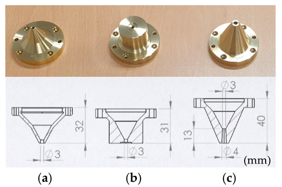
Figure 1.
Nozzle types and their cross-sectional views: (a) conical, (b) conical–flat, and (c) supersonic.
2. Experiments
2.1. Underwater Assist Gas Flow Visualization
To observe and analyze the assist gas flow, a dummy specimen made of transparent acrylic was prepared. A 100 mm-thick acrylic plate was placed underwater and formed a gap of 1 mm and 2 mm; the nozzle was placed on top of the acrylic plate. Experimental conditions are shown in Table 1. The assist gas flow pattern, depending on the gas pressure (Pg), the gap between acrylic plates (Gp), SOD (Dn), and nozzle types, was captured by the CCD camera as shown in Figure 2 and Figure 3. It was assumed that, when the penetration depth was deep, the assist gas flow rate between the cut surfaces was high, and the molten metal could be easily removed in the actual underwater laser-cutting process.

Table 1.
Underwater assist gas flow visualization test parameters.
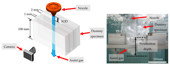
Figure 2.
Underwater assist gas flow visualization experiment setup.
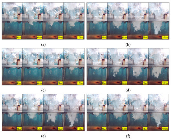
Figure 3.
Underwater assist gas flow visualization depending on the nozzle types, the gap between the plates (Gp), and the SOD (Dn). (a) Test No. 1-1: conical; Gp = 1 mm; Dn = 1 mm. (b) Test No. 1-2: conical; Gp = 2 mm; Dn = 1 mm. (c) Test No. 2-1: supersonic; Gp = 1 mm; Dn = 1 mm. (d) Test No. 2-2: supersonic; Gp = 2 mm; Dn = 1 mm. (e) Test No. 3-1: conical–flat; Gp = 2 mm; Dn = 1 mm. (f) Test No. 3-2: conical–flat; Gp = 2 mm; Dn = 0 mm.
Assist gas penetrated deeply in the experiments of test No. 1-1 and No. 1-2, as well as in the experiments of test No. 2-1 and No. 2-2, in the case of Gp = 2 mm. The penetration depth of the assist gas when Pg = 10 bar and Gp = 1 mm was almost the same as that of Pg = 6 bar and Gp = 2 mm. When comparing the experiments of tests No. 1-1 and No. 2-1, the penetration depth of the assist gas was less than expected when using a supersonic nozzle versus a conical nozzle. From the results of tests No. 1-2, No. 2-2, and No. 3-2, in the case of Gp = 2 mm, there was no significant difference in the penetration depth of assist gas depending on the nozzle types. From the experimental results of tests No. 3-1 and No. 3-2, when the Dn was set to 0 mm, the assist gas penetrated slightly deeper than Dn = 1 mm, but its effect was insignificant compared to effect of the differences in the gap between plates. Therefore, it can be assumed that increasing the kerf width in underwater laser cutting is the most dominant parameter for assist gas flow and aerosols generation reduction.
2.2. Underwater Laser Cutting
To verify the effect of the aforementioned cutting-process parameters, actual laser-cutting experiments were performed underwater, as shown in Figure 4. Liquid nitrogen was selected as an assist gas and an evaporator was used in order to maintain a high gas pressure. The IPG 20 kW fiber laser (YLS-20000) was used for the heat source of the thermal cutting. The shape of the cut specimen is shown in Figure 5. Stainless steel 304, with a dimension of 50 × 50 × 100 mm3, was used as a specimen. The SOD was set at 1 mm. Pre-flow gas was set to 1 bar in order to prevent the water flowing back into the nozzle while the laser-cutting head moved into the water pool (z-direction). The nozzle was positioned at the top edge of the specimen, the assist gas pressure was set, and the laser emission was initiated for cutting. The moving stage made the laser-cutting head move in the cutting direction (x-direction). To make an initial cut surface from the edge to 15 mm, the feed rate was set to 5 mm/min and, afterward, it was changed to a 30 mm/min feed rate.
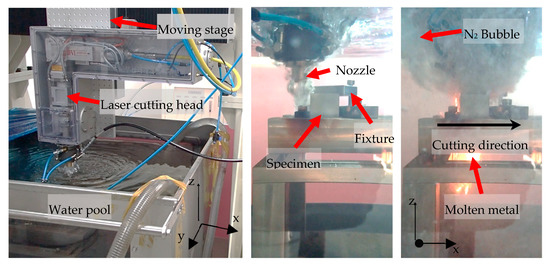
Figure 4.
Laser-cutting experiment setup.
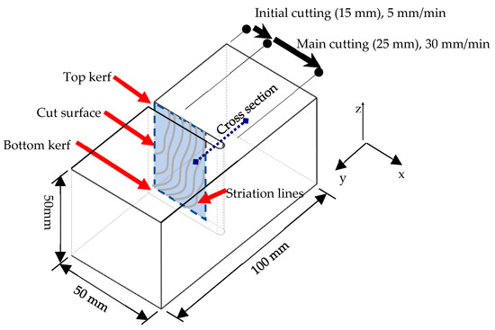
Figure 5.
Dimension and shape of cut specimen.
Three types of nozzles were used: conical, conical–flat, and supersonic. To adjust the top cut kerf width, the focus position of the laser was selected as a process parameter. The relationship between focus position and cut kerf width is plotted in Figure 6. The top kerf width can be formed if the focus position of the laser is located on the top surface of the specimen. As it became located deeper into the depth direction (defocus) of the specimen, the top kerf became wider.
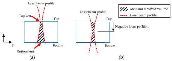
Figure 6.
Cross-sectional view of the laser-cut specimen depending on the laser beam focus position: (a) laser beam focus is positioned on the top surface of the specimen; (b) laser beam focus is positioned on the inside of the specimen.
3. Result and Discussion
3.1. Effect of Nozzle Type
To analyze the effect of the nozzle design, underwater laser-cutting experiments were performed using three types of nozzles. The other laser-cutting process parameters are shown in Table 2. The feed rate (Vc) is the moving speed of the laser-cutting head. The negative focus position of the beam (Fb) value means that the laser beam focus is located below the top surface of the specimen.

Table 2.
Laser-cutting process parameters depending on the nozzle types.
The top and bottom kerf widths were measured, and the cut surface was evaluated to check the cutting quality. In most thermal-cutting processes, striation lines can be observed on the cut surface due to the assist gas flow and molten metal flow.
The effect of the nozzle was evaluated through the cut surface analysis. As shown in Figure 7, there were three kinds of striation line zones on the cut surface: the upper, middle, and lower zones. The upper zone, where the striation line appeared in a straight line, and the momentum of the assist gas was more than enough to blow away the molten metal. The middle zone, where the molten metal was blown away by assist gas, but the striation line was appeared in a curved line. The lower zone, where the flow momentum of the assist gas was not enough to blow away the molten metal. The molten metal was flowed down, mainly due to the force of gravity and the weak assist gas momentum. From the point of view of cutting quality, the longer the length of the striation line of the upper and middle zones, the better the cutting quality. If the striation line of the upper zone and the middle zone was short, it means that the assist gas flow was not good because the assist gas was not sufficiently transferred between the cut surfaces. As shown in Figure 4, most of the assist gas changed to nitrogen bubbles on the top surface, and these bubbles produce the aerosols.
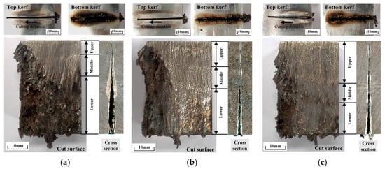
Figure 7.
Underwater laser-cutting results depending on the nozzle types: (a) conical, (b) conical–flat, and (c) supersonic.
As shown in Figure 7 and Table 3, laser cutting with a supersonic nozzle showed the best cut surface quality, followed by cutting with conical and conical–flat nozzles. However, in the case of using a supersonic nozzle, the top kerf width was measured approximately 50% larger than others. For some reason, the supersonic nozzle made a wider cut kerf and the molten metal was removed well compare to others.

Table 3.
Striation line length and kerf width depending on the nozzle type.
3.2. Effect of the Focus Position of Laser Beam
In order to find out the difference in laser cutting with respect to the kerf width, the focus position of the laser beam (Fb) was set to −20 mm and −30 mm. The other cutting conditions are shown in Table 4.

Table 4.
Laser-cutting process parameters.
The underwater laser-cutting results are shown in Figure 8 and Table 5. When Fb = −30 mm, the top kerf width (WTk) was increased by about 65% compared to Fb = −20 mm. The biggest change was the striation line length on the cut surface. Comparing Figure 8a,b, the upper and middle striation line lengths were long and the lower striation line length was short when WTk = 2 mm compared to when WTk = 1.3 mm. In the case of the wide kerf width, the flow momentum of the assist gas was maintained through the cutting section, and it blew away the molten metal. Additionally, in the case of Fb = −20 mm, a wide area of the melt and re-solidification area was observed as shown in the cross-sectional views presented in Figure 8a,c. This is because the molten metal was not well-removed from the cut surface and remained inside the cut surface.
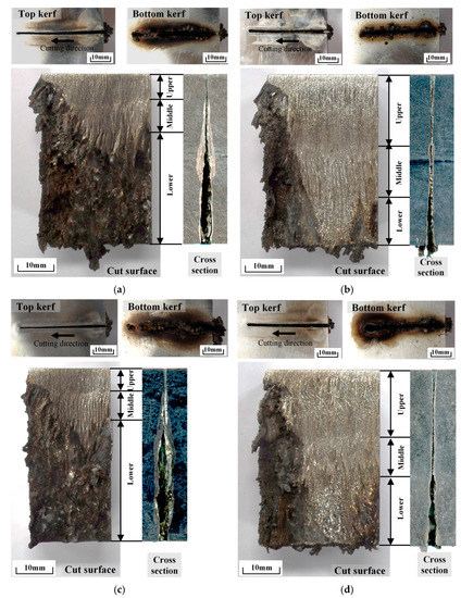
Figure 8.
Underwater laser-cutting results depending on the laser beam focus position and assist gas pressure. (a) Fb = −20 mm, Pg = 10 bar; (b) Fb = −30 mm, Pg = 10 bar; (c) Fb = −20 mm, Pg = 8 bar; (d) Fb = −30 mm, Pg = 8 bar.

Table 5.
Striation line length and kerf width depending on the beam focus position and the assist gas pressure.
To reduce the generation of aerosols, the assist gas pressure (Pg) was set to 8 bar and its cut surfaces are shown in Figure 8c,d. Comparing Figure 8a,d, even though the assist gas pressure was Pg = 8 bar, the top and the mid striation lines were longer than in the case of Pg = 10 bar and Fb = −20 mm.
3.3. Cut Surface Roughness Analysis
Kim et al. [20,21] measured the roughness of the cut surface after laser cutting to analyze the cutting quality, depending on the laser power and cutting speed. Similarly, the surface roughness was measured to determine how the change in the assist gas flow, according to the laser beam focus position, affects the quality of the cut surface. The maximum roughness depth (Rmax) value was used to compare the cut surface quality in the case of Fb = −20 mm and −30 mm, as show in Figure 9.
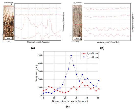
The difference in the surface roughness of the upper, middle, and lower striation lines was small in the case of Fb = −30 mm compared to Fb = −20 mm. When Fb = −20 mm, the surface roughness value was highest at 25 mm from the top surface, because the molten metal, which was delivered from the top, was solidified as it flowed down and created a molten metal flow pattern. As shown in the cross-sectional views presented in Figure 8a, it was observed that the most molten metal solidified in the middle of the specimen.
What we found through the analysis of striation line length and surface roughness was that the top kerf was widened due to the deep laser focus position. In addition, as assumed in Section 2.1, due to the widened kerf width, the flow of gas was improved and the molten metal was able to remove well.
4. Conclusions
In this study, assist gas visualization experiment was performed to find the most important process variable for reducing cutting gas pressure, which is directly related to aerosol generation in underwater laser cutting. Based on gas visualization experiment, actual underwater laser cutting was performed and cut surface was analyzed to evaluate the effect of the cutting process variables. The conclusions are as follows.
- From the underwater gas flow visualization experiment, the top kerf width was assumed to be the dominant factor in determining the assist gas flow and the penetration depth. The assist gas penetrated deeper with increasing Gp = 1 mm to 2 mm.
- In an actual underwater laser-cutting experiment, cutting performance was determined through cut surface analysis. This is because, when the upper and middle striation lengths were long and the surface roughness was low, it was observed that the assist gas flowed well inside the cut surface. Depending on the nozzle type, the cutting performance was best when supersonic nozzles were used. However, because the top kerf width also increased, it was hard to directly compare the nozzles’ effects on the cutting performance.
- When the focus of the laser Fb was positioned deeper into the depth direction of the specimen, the cutting performance was improved. In the case of Fb = −30 mm, the specimen was able to cut well, even though the gas pressure was reduced from 10 bar to 8 bar and the striation length was not changed significantly. This is because, as analyzed in the assist gas visualization experiment, the deeper the focus position of the laser beam, the wider the top kerf and the better the flow of assist gas inside the cut surface.
- Therefore, the top kerf width should be large enough to accommodate the easy removal of the molten metal. In underwater laser cutting, to reduce the generation of radioactive aerosols, the assist gas pressure was lowered by widening the kerf width. The kerf width was highly dependent on the laser beam focus position. Based on the results of this study, it is recommended to set the focus of the laser beam deep in the cutting object when dismantling the RVI underwater.
Author Contributions
Conceptualization, R.K.; methodology, R.K. and D.S.; investigation, R.K. and J.C.; resources, S.-J.L., J.C. and J.-D.K.; writing—original draft preparation, R.K.; writing—review and editing, S.-J.L. and D.S.; visualization, R.K.; supervision, D.S.; project administration, D.S.; funding acquisition, D.S. All authors have read and agreed to the published version of the manuscript.
Funding
This work was supported funded by the National Research Council of Science and Technology (Project number: NK238A, 2022, KOREA).
Institutional Review Board Statement
Not applicable.
Informed Consent Statement
Not applicable.
Data Availability Statement
The data presented in this study are available on request from the corresponding author. The data are not publicly available due to an ongoing study.
Conflicts of Interest
The authors declare no conflict of interest. The funders had no role in the design of the study; in the collection, analyses, or interpretation of data; in the writing of the manuscript, or in the decision to publish the results.
References
- Anunti, Å.; Larsson, H.; Edelborg, M. Decommissioning Study of Forsmark NPP (R-13-03); Swedish Nuclear Fuel and Waste Management Co.: Stockholm, Sweden, 2013; ISSN 1402-3091. [Google Scholar]
- Jain, R.K.; Agrawal, D.K.; Vishwakarma, S.C.; Choubey, A.K.; Upadhyaya, B.N.; Oak, S.M. Development of underwater laser cutting technique for steel and zircaloy for nuclear applications. Pramana 2010, 75, 1253–1258. [Google Scholar] [CrossRef]
- Khan, A.; Hilton, P. Optimisation of underwater laser cutting for decommissioning purposes. J. Laser Appl. 2014, 2014, 294–302. [Google Scholar] [CrossRef]
- Leschke, J.; Barroi, A.; Kaierle, S.; Hermsdorf, J.; Overmeyer, L. Studies on the Robustness of Underwater Laser Cutting of S355J2+N Using a Yb:YAG Disk Laser Source. Phys. Procedia 2016, 83, 310–316. [Google Scholar] [CrossRef]
- Shin, J.S.; Oh, S.Y.; Park, H.; Kim, T.-S.; Lee, L.; Chung, C.-M.; Lee, J. Underwater cutting of 50 and 60 mm thick stainless steel plates using a 6-kW fiber laser for dismantling nuclear facilities. Opt. Laser Technol. 2019, 115, 1–8. [Google Scholar] [CrossRef]
- Choubey, A.; Jain, R.; Ali, S.; Singh, R.; Vishwakarma, S.; Agrawal, D.; Arya, R.; Kaul, R.; Upadhyaya, B.; Oak, S. Studies on pulsed Nd:YAG laser cutting of thick stainless steel in dry air and underwater environment for dismantling applications. Opt. Laser Technol. 2015, 71, 6–15. [Google Scholar] [CrossRef]
- Peillon, S.; Fauvel, S.; Chagnot, C.; Gensdarmes, F. Aerosol Characterization and Particle Scrubbing Efficiency of Underwater Operations during Laser Cutting of Steel Components for Dismantling of Nuclear Facilities. Aerosol Air Qual. Res. 2017, 17, 1463–1473. [Google Scholar] [CrossRef]
- Kim, S.I.; Lee, H.Y.; Song, J.S. A study on characteristics and internal exposure evaluation of radioactive aerosols during pipe cutting in decommissioning of nuclear power plant. Nucl. Eng. Technol. 2018, 50, 1088–1098. [Google Scholar] [CrossRef]
- Segerud, P.; Boucau, J. Latest Experience from José Cabrera Reactor Vessel Dismantling Project–15214; WM Symposia, Inc.: Tempe, AZ, USA, 2015; pp. 1–9. [Google Scholar]
- Pospíšil, P. Reactor Vessel Internals Segmentation Experience using Mechanical Cutting Tools. Technol. Eng. 2013, 10, 6–10. [Google Scholar] [CrossRef][Green Version]
- Marimuthu, S.; Nath, A.K.; Dey, P.K.; Misra, D.; Bandyopadhyay, D.K.; Chaudhuri, S.P. Design and evaluation of high-pressure nozzle assembly for laser cutting of thick carbon steel. Int. J. Adv. Manuf. Technol. 2017, 92, 15–24. [Google Scholar] [CrossRef]
- Zhang, C.; Wen, P.; Yuan, Y.; Fan, X. Evaluation and optimal design of supersonic nozzle for laser-assisted oxygen cutting of thick steel sections. Int. J. Adv. Manuf. Technol. 2016, 86, 1243–1251. [Google Scholar] [CrossRef]
- Orazi, L.; Darwish, M.; Reggiani, B. Investigation on the Inert Gas-Assisted Laser Cutting Performances and Quality Using Supersonic Nozzles. Metals 2019, 9, 1257. [Google Scholar] [CrossRef]
- Oh, S.Y.; Shin, J.S.; Kim, T.S.; Park, H.; Lee, L.; Chung, C.-M.; Lee, J. Effect of nozzle types on the laser cutting performance for 60-mm-thick stainless steel. Opt. Laser Technol. 2019, 119, 105607. [Google Scholar] [CrossRef]
- Tamura, K.; Toyama, S. Laser cutting performances for thick steel specimens studied by molten metal removal conditions. J. Nucl. Sci. Technol. 2017, 54, 1011–1017. [Google Scholar] [CrossRef]
- Goppold, C.; Pinder, T.; Herwig, P. Dynamic Beam Shaping for Thick Sheet Metal Cutting. LiM 2017, 1–9. [Google Scholar]
- Morimoto, Y.; He, D.; Hijikata, W.; Shinshi, T.; Nakai, T.; Nakamura, N. Effect of high-frequency orbital and vertical oscillations of the laser focus position on the quality of the cut surface in a thick plate by laser beam machining. Precis. Eng. 2015, 40, 112–123. [Google Scholar] [CrossRef]
- Man, H.; Duan, J.; Yue, T. Design and characteristic analysis of supersonic nozzles for high gas pressure laser cutting. J. Mater. Process. Technol. 1997, 63, 217–222. [Google Scholar] [CrossRef]
- Shin, J.S.; Oh, S.Y.; Park, H.; Chung, C.M.; Seon, S.; Kim, T.S.; Lee, L.; Lee, J. Laser Cutting of Steel Plates up to 100 mm in Thickness with a 6-KW Fiber Laser for Application to Dismantling of Nuclear Facilities. Opt. Lasers Eng. 2018, 100, 98–104. [Google Scholar] [CrossRef]
- Kim, K.; Song, M.-K.; Lee, S.-J.; Shin, D.; Suh, J.; Kim, J.-D. Fundamental Study on Underwater Cutting of 50 mm-Thick Stainless Steel Plates Using a Fiber Laser for Nuclear Decommissioning. Appl. Sci. 2022, 12, 495. [Google Scholar] [CrossRef]
- Kim, K.; Song, M.K.; Kim, J.D.; Lee, S.J.; Shin, D.; Cho, D.W. Effect of assist gas pressure on cutting quality in underwater cutting of stainless steel using high-power fiber laser. Mod. Phys. Lett. B 2022, 36, 2242012. [Google Scholar] [CrossRef]
Publisher’s Note: MDPI stays neutral with regard to jurisdictional claims in published maps and institutional affiliations. |
© 2022 by the authors. Licensee MDPI, Basel, Switzerland. This article is an open access article distributed under the terms and conditions of the Creative Commons Attribution (CC BY) license (https://creativecommons.org/licenses/by/4.0/).
