Article

Study on Characteristics and Optimal Layout of Components in Shallow Water Mooring System of Floating Wind Turbine

1
College of Shipbuilding Engineering, Harbin Engineering University, Harbin 150001, China
2
Yantai Research Institute, Harbin Engineering University, Yantai 264006, China
*
Author to whom correspondence should be addressed.
Appl. Sci. 2022, 12(19), 10137; https://doi.org/10.3390/app121910137
Submission received: 8 September 2022 / Revised: 27 September 2022 / Accepted: 29 September 2022 / Published: 9 October 2022
(This article belongs to the Section Marine Science and Engineering)

Abstract

:
Offshore wind energy resources far exceed those on land. However, the increase in water depth of the continental shelf in China’s sea area slows down as the distance from the shore increases. In view of the characteristics of China’s sea, how to optimize the design of mooring systems to adapt to the water depth conditions in China’s waters and to resist the harsh sea conditions is one of the major problems encountered in the development of floating wind turbines. In this paper, the 5MW-OC4 semi-submersible floating wind turbine is taken as the research object, and the frequency domain and time domain calculation of the floating wind turbine are carried out by using SESAM software under the water depth of 40 m in the Bohai Sea. By comparing the motion response and tension of catenary and tension mooring floating wind turbine. The mooring system is optimized by combining the buoy and clump weight. The results show that the catenary mooring mode is more suitable for the floating wind turbine under shallow water conditions. Mooring accessories used in combination have the same effect on the overall response of the floating wind turbine as changing the same mooring parameters when used alone, but the effect of changing the mooring parameters on the performance optimization of the mooring system is more obvious when used in combination, and a reasonable combination of accessories can significantly change the overall characteristics of the floating system and affect the safety and cost of the system.

1. Introduction

Wind energy, as the clean energy with the most vigorous development in recent years, has attracted the attention of all countries in the world. China’s investment in the wind power industry has also greatly increased. After the proposal to achieve carbon neutrality before 2060, the development of the wind power industry has entered a golden age. Compared with land-based fixed wind turbines, offshore wind power not only has more abundant wind resources, but also solves the problem of fixed wind power. The vision and noise of wind turbines and other issues, the wind power industry from land to sea must be the general trend of future development. The increase in the water depth of the continental shelf in China’s waters is small, and the water depth in offshore waters is basically less than 60 m [1,2,3]. Therefore, it is necessary to study the development of floating wind turbines in shallow water conditions, and how to design and optimize them to adapt to small water depths and withstand harsh sea conditions. It is also one of the key issues in the current development of floating wind turbines.
The first use of buoys and clump weights to optimize mooring systems dates back to 1976, Finn et al. [4] proposed “The guyed tower”, when the platform encounters extreme sea conditions, the response of the platform is too large, and the mooring system lifts the clump weights from the seabed, which can be regarded as the extension of the catenary to reduce the motion response of the partial platform.Morrison and Asce [5] further proved the significant resistance of the guyed tower to horizontal loads due to the influence of clump weights. Mavrakos et al. [6,7] investigated the optimization effect of buoys on the mooring system and determined that the mooring system can be optimized when the size, quantity and location of the buoys are selected reasonably. By 1997 Mavrakos and Chatji-georgiou [8] did the analysis in the frequency domain as well as the time domain. Fitzgerald et al. [9] applied buoys to the wave energy converters at 50 m water depth, which proved that the use of buoys on mooring lines can significantly reduce the weight of mooring lines and have a significant impact on the motion response of marine structures. Yuan et al. [10] proposed a novel hybrid mooring system suitable for deep-water semi-submersible platforms with clump weights and buoys. Through the time-domain coupling analysis, it is found that the hybrid mooring system can improve the ship’s deflection problem and reduce the tension of the mooring line. Xiao et al. [11] took a NREL 5MW floating wind turbine as the research object, and proposed a mooring system using pure anchor chain, clump weight anchor chain, elastic cable and nylon cable as mooring materials. The dynamic response characteristics of mooring system are studied by displacement, mooring tension and engine room acceleration. Xu et al. [12] proposed seven mooring schemes using different materials, mooring accessories, and anchors based on a 5MW semi-submersible floating wind turbine at a water depth of 50 m. The geometric and elastic mooring stiffness was fully utilized to compare the design options, and the advantages and disadvantages of the seven schemes were analyzed by static, attenuation, dynamic, and cost analyses.
The rational combination of mooring accessories such as buoys, clump weights and mooring lines can become one of the breakthroughs in how to design and optimize the mooring system so that it can adapt to small water depths and resist harsh sea conditions. In this paper, the 5MW-OC4 semi-submersible floating wind turbine is used as the research object, and SESAM software is used to calculate the frequency domain and time domain of the floating wind turbine at a depth of 40 m in the Bohai Sea. According to the motion response and tension of the wind turbine, choose a mooring method with better performance. The combined use of buoys, clump weights and mooring lines can reasonably distribute mooring stiffness and reduce mooring tension. The influence of separate and combined use of buoys and clump weights on the motion response of floating wind turbines and the tension of mooring system are analyzed, studying the performance optimization effect of the mooring system by changing the same mooring parameters when the accessories are used alone and in combination, and select the best combination of accessories to optimize the mooring system.

2. Methodology

2.1. Blade-Element Momentum Theory

The principle of the blade element momentum theory [13] is based on the conservation of the momentum of the air flowing through the rotor disk between the local force generated by the empirical lift coefficient and the empirical drag coefficient at the airfoil. The basic idea of blade element momentum theory is to simplify the wind turbine blade into several blade element units of length dr in the span direction, and assuming that there is no interaction between the micro-segments of the blade element unit, the force on each blade can be approximated by the superposition of the spanwise integrals on each blade element, at the position r between the rotor and the hub center, the thrust and torque of the blade element unit on the rotor are:
d T = N d F X = 0.5 ρ V 0 2 N C C X d r
d M = N r d F Y = 0.5 ρ V 0 2 N r C C Y d r
C X = C L cos ϕ + C D sin ϕ
C Y = C L sin ϕ C D cos ϕ
where v 0 is the relative velocity on the blade, C is the chord length of blade element, C L is the lift coefficient, C D is the resistance coefficient; d r represents the length of blade element; N is the number of blades.

2.2. Frequency Domain Analysis Theory

For large-scale marine structures, the velocity potential is generally solved based on the three-dimensional potential flow theory. The motion frequency domain response equation of the platform can be written as:
ω 2 M f + A + ( i ω C + K ) u = F w
where M f is the mass matrix of the floating body system, A is the Additional mass matrix, C is the additional damping matrix, K is an additional water static matrix. u is the motion response of floating body in complex form, F w is wave excitation force, ω is the incident wave frequency.

2.3. Time Domain Analysis Theory

In the time domain motion, the motion equation of the floating wind turbine platform is:
M p + A x ( t ) + D x . ( t ) + K t x ( t ) + 0 R ( t τ ) x . ( t ) d τ = F ( t )
F ( t ) = f w 1 + f w 2 + f w i n d   + f c u + f e x t
where M P is the mass matrix of the floating wind turbine, A the low-frequency added mass matrix, x is the motion displacement corresponding to the degree of freedom, t is the time of time domain simulation, D is the drift damping matrix, K t is the total stiffness matrix, R is the velocity pulse function matrix, F(t) is the external load at time t, f w 1 is the first-order wave load, f w 2 is the second-order wave load, f w i n d is the wind load, f c u is the current load, f o t h e r is the other load.

3. Model Parameter

3.1. Winf Turbine Parameters

Here selects the 5MW OC4-DeepCwind semi-submersible floating wind turbine (Figure 1) released by the American National Renewable Energy Laboratory (NREL) as the research object. The wind turbine is a three-impeller structure with a horizontal axis, the specific parameters are shown in Table 1.

3.2. Parameters of Floating Platform

The environment of floating platform is under the condition of 40 m water depth in Bohai sea. Compared with the TLP [14,15] and Spar platforms [16,17,18,19,20], the semi-submersible floating platform [21,22,23,24,25] has low cost and less construction difficulty in small water depth. The OC4-DeepCwind semi-submersible platform is mainly composed of three cylinders with a diameter of 12 m, and the bottoms of the three cylinders are respectively connected with three cylinders with a diameter of 24 m. There is a central support column with a diameter of 6.5 m in the middle of the three columns. Between the columns is a series of horizontal diagonal cross braces with a diameter of 1.6 m. The geometric dimensions are shown in Figure 1, and the specific parameters are shown in Table 2.

3.3. Mooring Parameters

The mooring system is the main part to ensure the stability of the floating wind turbine. In order to design a mooring system suitable for the small water depth in the Bohai Sea, the motion response and tension of the two mooring systems were analyzed and compared when selecting the mooring system, the first uses tension mooring and the second uses catenary mooring. Both mooring systems use three mooring lines, each with an included angle of 120°. The mooring lines are connected to fairleads on flat cylinders 14 m below the static water surface, and the anchors are located at a water depth of 40 m. The parameters of the two mooring systems [26] are shown in Table 3.

3.4. Environmental Parameters

The 40 m water depth condition in Bohai Sea of China is selected as the working water depth, the sea conditions are selected as extreme sea conditions that occur once in 50 years in the Bohai Sea, and the JONSWAP spectrum is selected as the wave spectrum, the specific data is shown in Table 4, the wave incident angle, the direction of wind and current are 0°, and the mooring line 2 is windward cable.

4. Numerical Simulation

4.1. Coupling Model Validation

In order to ensure the accuracy of the simulation of the coupled model by the numerical tools used in this paper, SIMA was used to simulate the response of the coupled model for 3 h. The obtained results were compared with the 1:50 model test results of OC4-DeepCWind released by NREL and the FAST simulation results [27]. First verify the free decay simulation of the floating wind turbine. Figure 2 shows that the simulated vertical oscillation response of SIMA under the action of irregular waves alone is basically the same as the experimental and Fast results, and the longitudinal oscillation response is basically the same as the Fast results but slightly smaller than the experimental results. Secondly, in order to further judge the accuracy of the coupled model simulation results, and experiments using the same turbulent wind and irregular wave joint action for verification. Figure 3 shows that the mean values of longitudinal oscillation, longitudinal rocking and tension of SIMA’s simulated floating wind turbine under combined wind and wave conditions are basically the same as the test results, and the maximum value of tension is slightly smaller than the test value. This result should be due to the different amplitudes produced by the different random seeds generated by turbulent winds and irregular waves during the simulation. Overall the results are generally consistent, indicating that SIMA is able to accurately predict the kinematic response of the floating wind turbine in the presence of turbulent winds and irregular waves, demonstrating the accuracy of the numerical tool used in this paper for coupled model simulations.

4.2. Frequency Domain Hydrodynamic Analysis

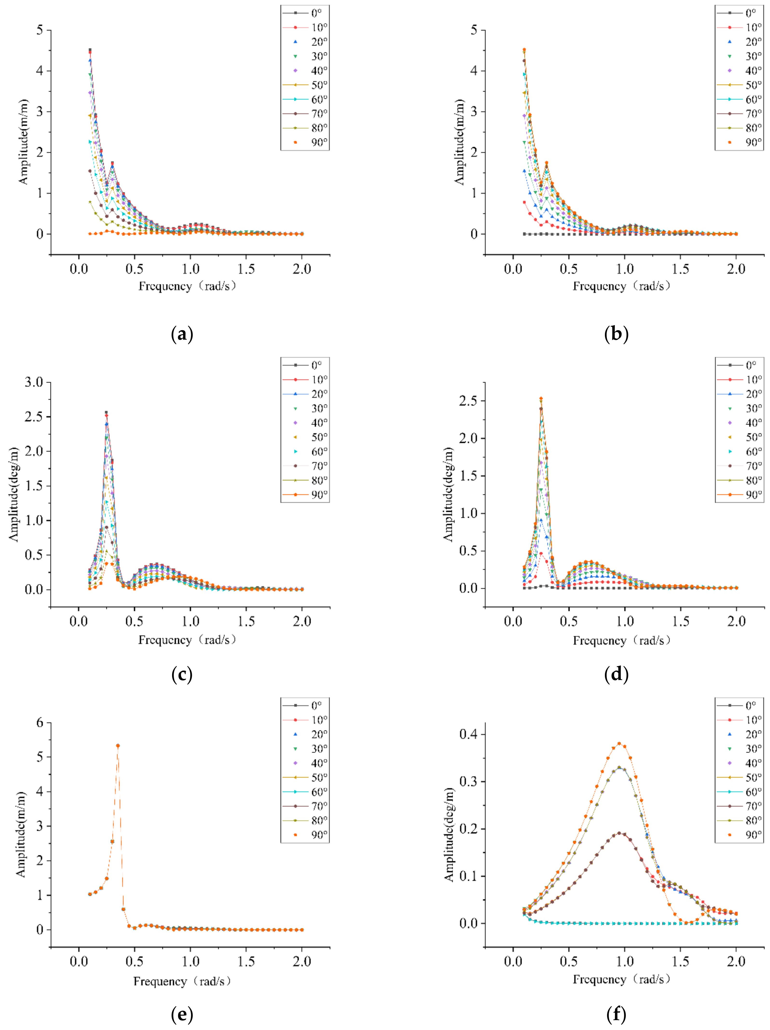
Before the time domain coupling analysis of the floating turbine, a frequency domain hydrodynamic analysis of the OC4-DeepCwind semi-submersible platform needs to be performed at a water depth of 40 m using the HydroD module in the SESAM software. In HydroD, the frequency is taken to be 0.1 to 2.0 rad/s with a frequency interval of 0.05 rad/s, and the wave direction is taken at 10° intervals, and the results are shown in Figure 4.

4.3. Analysis and Comparison of Tensioned and Catenary Mooring Systems

In order to select a mooring system with better performance in small water depth, two mooring methods are used to simulate the floating wind turbine under the same working conditions. The irregular wave is simulated by JONSWAP wave spectrum. The significant wave height is 6.42 m and the peak period is 11.58 s, the wind speed of steady wind is 21 m/s. The time-domain coupling results of floating wind turbine using two different mooring systems are compared and analyzed. The total time of SIMA simulation response process is 10,800 s, and the three degrees of freedom that are greatly affected by wind, wave and current conditions in the time-domain coupling results are mainly compared and analyzed. Response and tension, the three degrees of freedom are surge, heave and pitch [28].
Under the same working conditions, the motion response and tension comparison of the tensioned and catenary floating wind turbines are shown in Figure 5. Comparing and analyzing the motion response, tension time history curve and statistical results obtained by the two mooring methods of the floating wind turbine. We can see that: The mean value of the surge of the tensioned mooring is smaller than the mean value of the catenary, but the standard deviation of the tensioned mooring is larger than that of the catenary mooring. It shows that the dispersion degree of the motion response amplitude of the tensioned mooring is larger than that of the catenary mooring; The maximum value, mean and standard deviation of the heave and pitch of the catenary mooring are smaller than those of the tensioned mooring, indicating that the catenary mooring is better than the tensioned mooring in the response of heave and pitch; The No. 2 mooring line is the windward line of the floating wind turbine, so the tension of the No. 2 mooring line is mainly analyzed. From Table 5, it is not difficult to see that the maximum value of the catenary mooring tension is smaller than that of the tensioned mooring, while the average and the standard deviation is much smaller than that of the tensioned mooring. Although the maximum tension of the two mooring methods is smaller than the breaking tension, the maximum tension of the tensioned mooring is obviously larger.
In general, although the mean value of the catenary mooring system’s surge is greater than that of the tensioned mooring, considering that the suspension section of the catenary mooring is shorter in small water depth, the positioning ability of the floating wind turbine in the windward direction is better, and the discrete degree of the catenary mooring’s pitch motion response is smaller than that of the tensioned mooring. Comparing the heave and pitch motion responses, it can be seen that the catenary mooring system is more effective in motion control. Considering the size of the tension, the catenary mooring system has better safe operation ability, so considering the advantages and disadvantages of both, it is more reasonable for the floating wind turbine to choose the catenary mooring system.

4.4. Individual Accessory Parameter Sensitivity Analysis

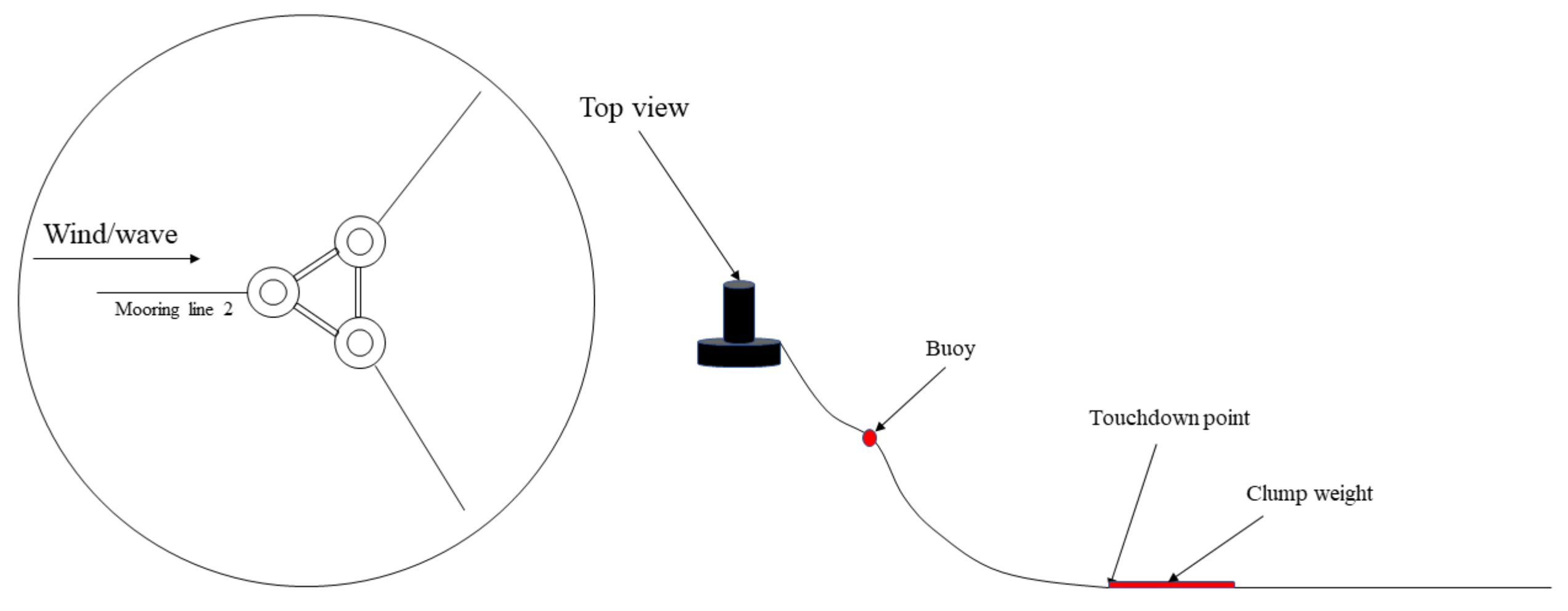
The recovery force of the floating wind turbine mooring system in the shallow water environment mainly comes from the gravity of the catenary, but the small water depth limits the length of the mooring suspension section. In order to ensure that the mooring system can have sufficient recovery force and the cost is within the controllable range within the mooring line, buoys and clump weights can be added to increase resilience [29,30,31]. The combined use of buoys and clump weights can reasonably distribute the mooring stiffness, reduce the mooring tension, and reduce the motion response of the platform, etc. In order to design and optimize a mooring system that is suitable for small water depths in the Bohai Sea and can resist harsh sea conditions (in Figure 6), it is necessary to analyze and compare the optimization effects of different combinations of buoys and clump weights on the mooring system. Before analyzing the use of buoys and clump weights in combination for mooring system optimization, the effect of the change of fitting parameters on the mooring system when using mooring fittings alone is studied.

4.4.1. Buoy Volume and Installation Location

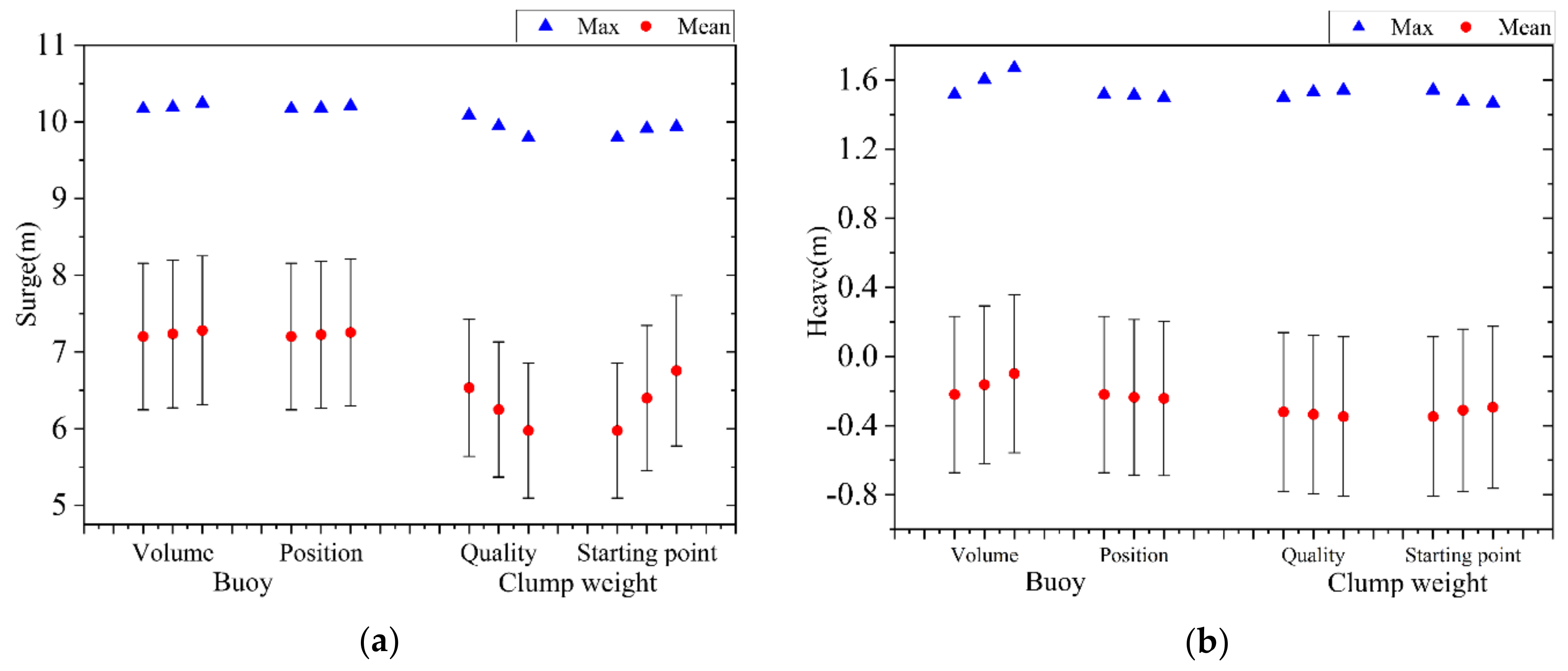
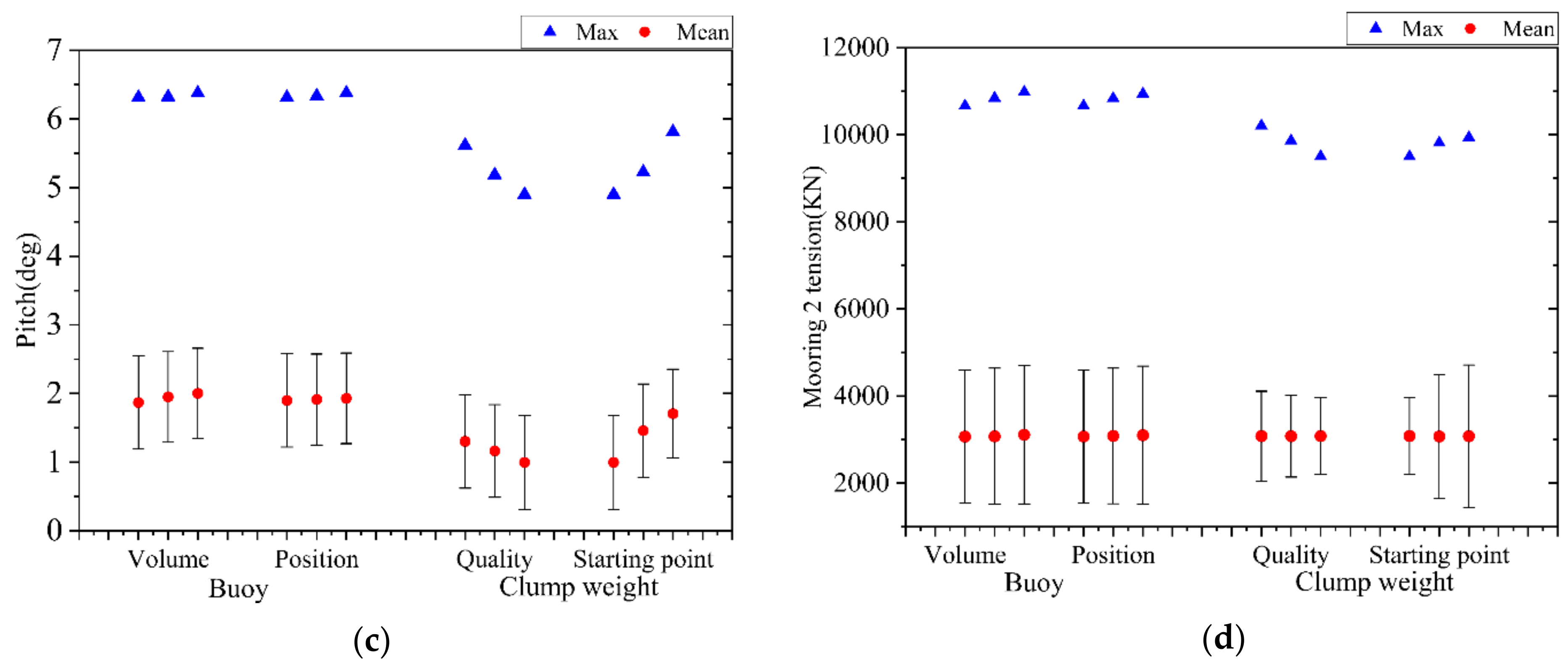
Adding a buoy to the catenary mooring system can provide an upward force that reduces the weight of the o catenary. In order to study the influence of the change of buoy parameters on the overall response of the wind turbine, the influence of different volumes of buoys on the performance of the mooring system was first compared. The three buoy volumes were 10 m3, 20 m3 and 30 m3 respectively, and the buoys were installed 15 m away from the fairlead; Secondly, consider the optimization effect of float installation position change on the overall motion response of the wind turbine, the buoy with a volume of 10 m3 is selected, and the installation position is 15 m, 25 m, and 35 m from the fairlead respectively. Using SIMA to simulate the motion response of the floating wind turbine with different buoy parameters under extreme sea conditions for 3 h, the motion response and tension statistics of the floating wind turbine under different buoy parameters were obtained.
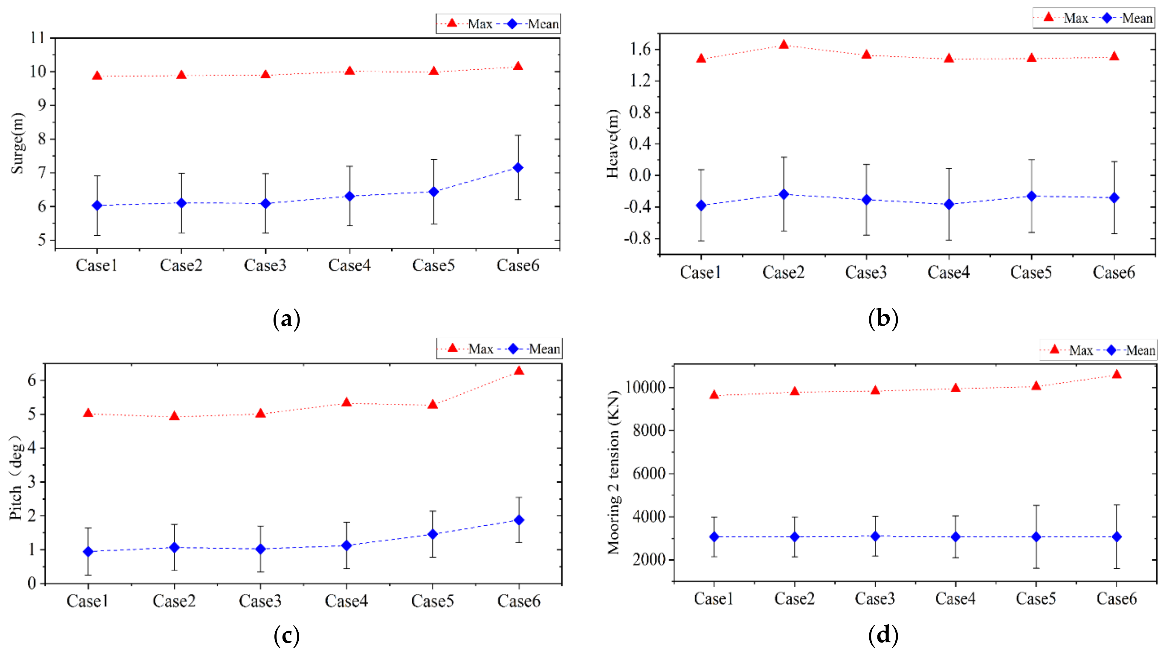
The motion response and tension of the floating wind turbine with different buoy parameters can be seen in Figure 7, and the motion response of triangle tag represents the response statistics of maximum value, round mark on behalf of the mean, the error bars represent the standard deviation. It can be seen from the figure that when the buoy is installed separately on the floating wind turbine mooring system, increasing the volume of the buoy under the condition of determining the installation position will increase the mean and maximum value of the surge, pitch and heave, the maximum value of the No. 2 mooring line tension increases, but the mean value of the mooring line tension changes very little; When determining the volume of the buoy, the distance between the installation position of the buoy and the fairlead increases, which will lead to an increase in the maximum and mean value of the surge and pitch, but will reduce the mean and maximum value of the heave, the maximum tension of mooring line 2 will also increase, and the average value will remain basically unchanged.

4.4.2. The Mass of the Clump Weight and the Installation Position

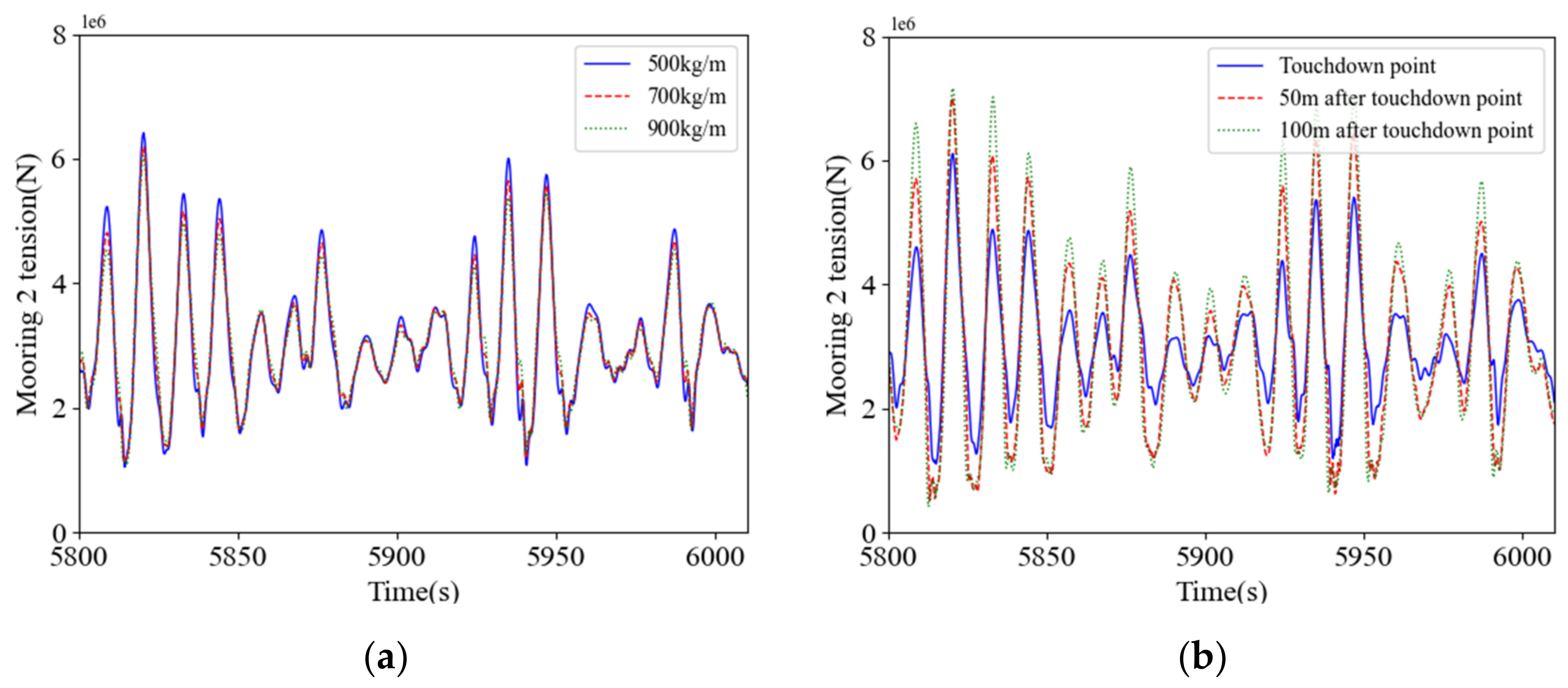
Installing clump weights on the catenary increases the vertical component and the overall tension of the line, thereby increasing the mooring system recovery. In order to obtain the influence of the parameter change of the clump weight on the performance of the mooring system, the optimization effect of the mass of the clump weight on the mooring system is first considered. The starting point of the installation position of the clump weight is located at the contact point between the mooring and the seabed, and the assembly length is 50 m, the mass of the clump weights is 500 kg/m, 700 kg/m, 900 kg/m; Secondly, considering the influence of the installation position of the clump weight on the overall response of the floating wind turbine, the mass of the clump weight is 900 kg/m. The starting points of the mooring installation clump weight are set at the touchdown point, 50 m after the touchdown point, and 100 m after the touchdown point, and keep the assembly length at 50 m.SIMA was used to simulate the motion response of the floating wind turbine under extreme sea conditions under different parameters of the clump weight block for 3 h, and the motion response and tension statistical results of the floating wind turbine with different clump weight parameters were obtained.
Figure 7 shows the motion response and tension of the floating wind turbine under different clump weight parameters. The triangle marks represent the maximum value of the response statistics, the circle marks represent the mean, and the error bars represent the standard deviation. It can be seen from Figure 7 that when the floating wind turbine mooring system installs the clump weight alone. Determining the installation position of the clump weight, and increasing the mass of the clump weight can reduce the maximum and average value of the surge and pitch, while the mean value of heave decreases and the maximum value increases. In (a) of Figure 8, it can be seen that the maximum tension value of the No. 2 mooring line decreases, the mean value does not change much, but the oscillation amplitude decreases; When the mass of the clump weight is determined, as the installation position moves backward, the maximum and mean value of the heave, pitch and pitch of the floating wind turbine increase, while the maximum value of the heave decreases and the mean value increases. In (b) of Figure 8, it can be seen that the average value of the tension of the No. 2 mooring line changes very little, and the maximum value and the amplitude are both increasing.

4.5. Sensitivity Analysis of Accessory Combination Usage Parameters

According to the above comparative analysis, it can be concluded that the parameters with the best optimization effect on the mooring system when the buoy and the weight are used alone. In order to find the best combination of parts to optimize the overall response of the floating wind turbine, and to verify that there is no influence between the mooring parts, the control variable method is used to verify. After changing one of the parameters, compare it with the optimal solution. The specific solution is shown in Table 6. Using SIMA to simulate the motion response of the floating wind turbine under extreme sea conditions for 3 h under different parameter combinations of mooring accessories, the motion response and tension statistics of the floating wind turbine are obtained.
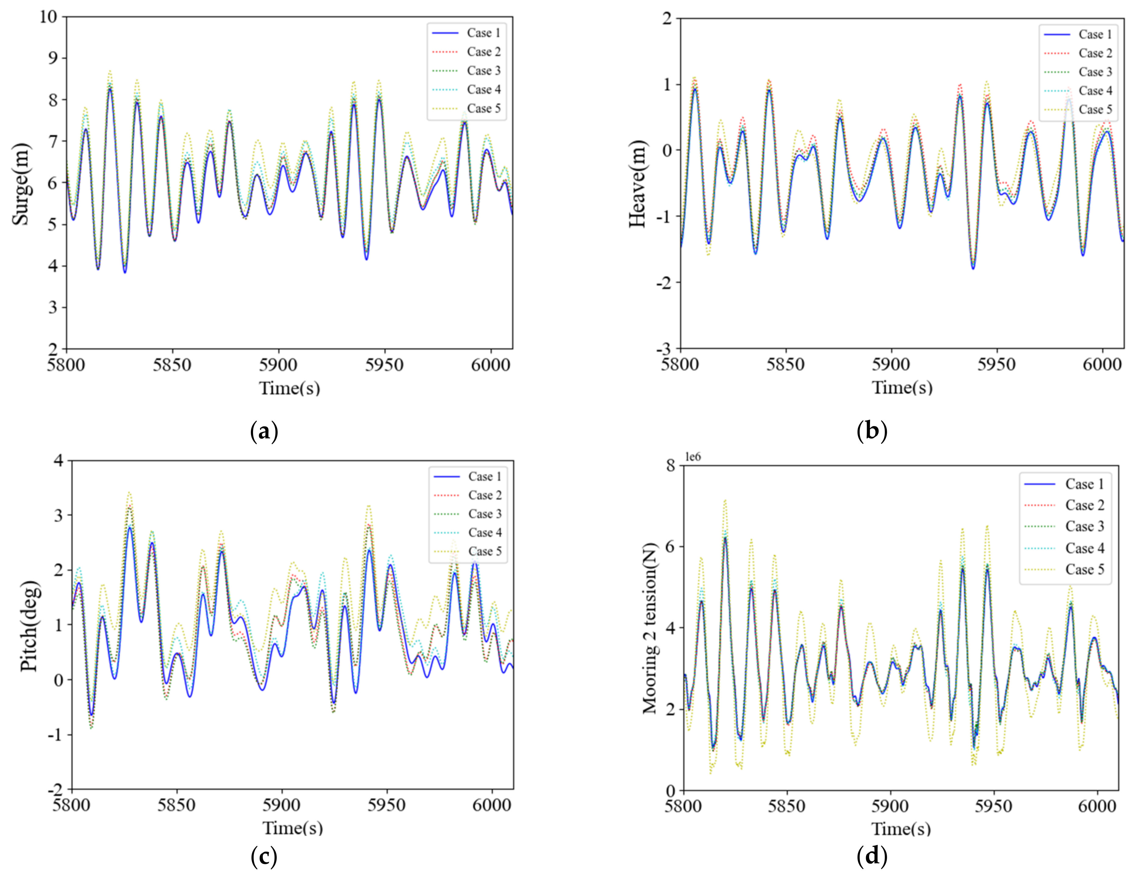
Figure 9 is the comparison chart of the motion response and tension of the floating wind turbine when the accessories are combined. In order to make the comparison result more clearly visible, the relatively stable 5800–6000 s of the 10,800 s time history response curve of the floating wind turbine in the time domain is selected for comparison, as shown in Figure 10. Case 2~Case 5 are the schemes after changing a mooring accessory parameter in Case 1, and Case 6 is the scheme without mooring accessories. The comparison with Case 6 shows that the combination of accessories has a significant effect on the optimization of the response of the floating wind turbine, while the comparison with Case 1 shows that the optimization effect of Case 1 is better than the other solutions, which means that the combination of accessories does not affect the optimization law of the mooring system when the accessories are used alone.
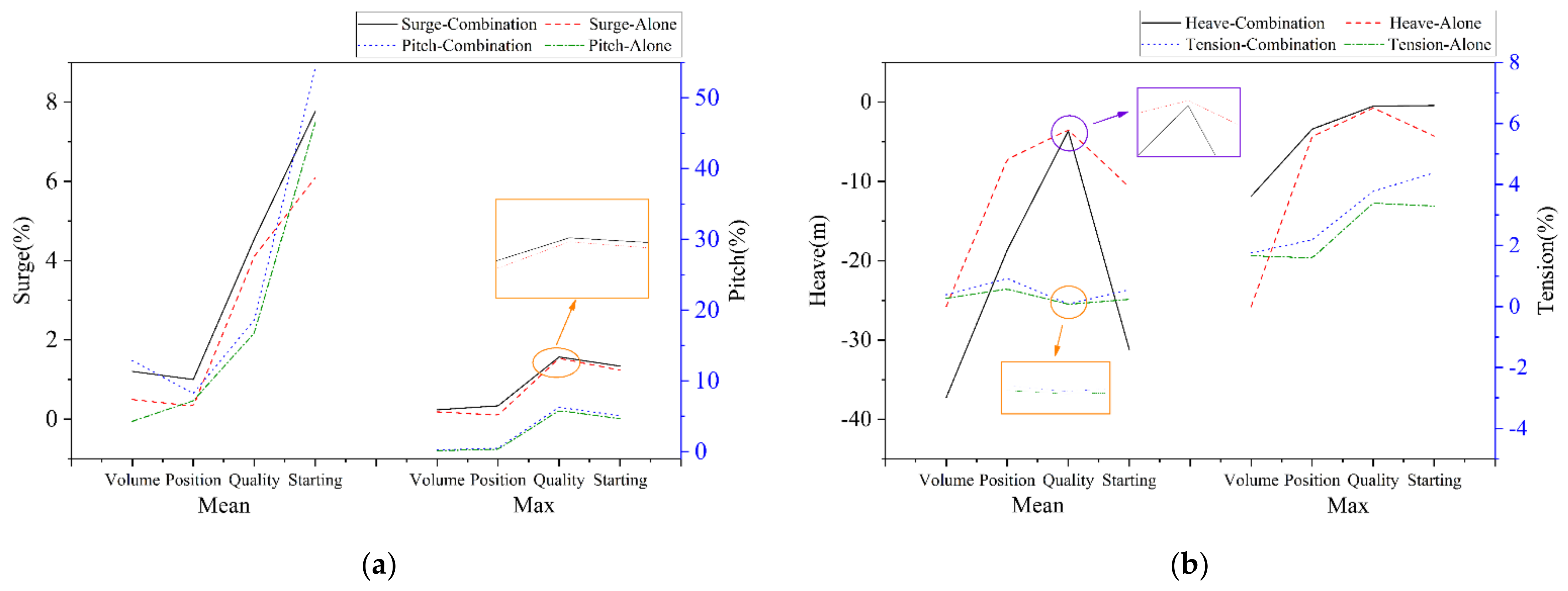
In order to further explore whether the mooring accessories will improve the performance optimization effect of mooring system when the mooring accessories are used in combination compared with the accessories alone, the percentage of performance improvement of the mooring system after the parameters are changed when the accessories are used in combination is calculated, and the change is the same as when the accessories are used alone. The percentage of mooring performance improvement after fitting parameters is compared, as shown in Figure 11. In the figure, we can see that although the difference in the improvement rate of mooring performance by changing some of the parameters is small, on the whole, changing the parameters of the accessories when the accessories are used in combination has a greater impact on the performance of the mooring system than changing the same parameters when using the accessories alone. And I can see from the graph that the points where the difference is smaller are generally concentrated when changing the mass of the clump weight. Table 7 also shows that in addition to the pitch response, the difference between the mean and maximum values of the surge, heave, and tension when changing the mass parameters of the clump weight is much smaller than other parameters. This indicates that when changing the mass parameter of the clump weight, whether it is used in combination with the buoy has little effect on the overall response, and the change in the mass parameter of the clump weight has a greater effect on the overall response of the wind turbine. Therefore, the clump weight mass has a greater influence on the mooring system compared to other parameters. When the clump weight mass parameters are changed the difference in lift rates for the floating wind turbine mooring system, whether the accessories are used alone or in combination, is small because the difference in the overall response of the two is small.

5. Conclusions

This paper uses a 5MW-OC4 semi-submersible floating wind turbine as the research object to compare and analyze the optimization results of the overall response of the floating wind turbine when the accessories are used alone and in combination, and draws a link between the mooring accessories and the overall response of the floating wind turbine, which provides a reference and reference for the design of mooring systems in small water depth in the Bohai Sea in the future. From the above analysis and discussion, several important conclusions can be drawn, as follows.
  • At small water depths, when the span between catenary and tensioned moorings is the same, the catenary mooring is better than the tensioned mooring in terms of droop and longitudinal rocking motion response and tension. In the aspect of surge, the positioning ability of the tensioned mooring is better than that of the catenary type, and the motion control ability is worse than that of the catenary type. Considering the advantages and disadvantages of both and the safe operation ability of floating wind turbines in complex marine environments, catenary mooring is a more suitable mooring mode.
  • After the buoy and clump weight are added to the floating wind turbine mooring system, the surge and pitch motion responses can be obviously optimized, and the maximum of the mooring tension can be reduced, but the heave motion response is slightly increased due to the characteristics of the clump weight and buoy.
  • When mooring accessories are used alone, increasing the volume of the buoy will increase the maximum value and average value of surge, heave and pitch, and the maximum value of tension will also increase; When the installation position of the buoy moves down within a certain range, the maximum and mean values of the pitch and pitch will increase, but the maximum and mean values of the heave will decrease, and the mooring line tension will also increase. The increase in the mass of the clump weight will reduce the maximum value and the mean value of the heave and pitch, the maximum value of the heave will increase but the average value will decrease, while the maximum value of the mooring line tension will decrease, and the amplitude of the oscillation will also decrease. If the installation position of the clump weight is moved backward within a certain range, the maximum value and average value of surge and pitch will increase, the maximum value of heave will decrease but the average value will increase, and the maximum value of tension and the amplitude of oscillation will increase.
  • The combination of the use of accessories to change the parameters of the overall response of the floating wind turbine the same law as the use of accessories alone when changing the same parameters. However, the rate of improvement of the mooring system optimization by changing the mooring parameters when used in combination is higher than the result of changing the same parameters when the accessories are used alone; The optimization difference of the maximum heave motion response can reach 24.6%, and the optimization difference of the mean value can reach 30.1%. The surge, pitch and tension difference are basically within 10%.
  • When changing the mass parameters of the clump weight, the maximum difference of the heave, pitch and tension response of the fan is 1.837% and the minimum is only 0.006% under the condition of the single and combined use of the accessories, which is much smaller than the optimization difference caused by changing other parameters. This shows that when changing the mass parameters of the clump weight, whether it is used in combination with the buoy has little effect on the overall response. So it is not difficult to see that the clump weight mass parameters have a greater impact on the mooring system than other parameters.

Author Contributions

X.Z. and T.Z. made the computations and data analysis; Z.H. made the data analysis and did the proofreading; G.M. did the proofreading and editing; X.Z. guided the engineering project and provided the data; T.Z. drafted the manuscript with others. All authors contributed to the work. All authors have read and agreed to the published version of the manuscript.

Funding

This research work was funded by the National Key Research and Development Program of China (No. 2020YFB1506701), the National Natural Science Foundation of China (Nos. 51739001; 51879051); Natural Science Foundation of Heilongjiang Province in China (LH2020E071), Open Fund of Zhejiang Provincial Key Laboratory of Wind Power Technology (ZOE2020007).

Institutional Review Board Statement

Not applicable.

Informed Consent Statement

Not applicable.

Data Availability Statement

The data sets during and/or analyzed during the current study are available from the corresponding author upon reasonable request.

Acknowledgments

We sincerely thank Qingwei Ma in City, University of London, corresponding editors and re-viewers for their constructive suggestions and supports.

Conflicts of Interest

The authors declare no conflict of interest.

References

  1. Fan, K. Motion performance of floating offshore wind turbine platform in shallow water. J. Mar. Eng. 2021, 43, 71–76. [Google Scholar]
  2. Xu, K.; Gao, Z. Effect of hydrodynamic load modelling on the response of floating wind turbines and its mooring system in small water depths. IOP Publ. 2018, 1104, 012006. [Google Scholar] [CrossRef] [Green Version]
  3. Zhang, L.; Li, H. A combination mooring system and mooring characteristics study. J. Ship Mech. 2016, 20, 306–314. [Google Scholar]
  4. Finn, L.D. A New Deepwater Offshore Platform-The Guyed Tower. In Proceedings of the Offshore Technology Conference, Houston, TX, USA, 2–5 May 1976. [Google Scholar]
  5. Morrison, G.D. Guyed Tower with Dynamic Mooring Properties. J. Struct. Eng. 1983, 109, 2578–2590. [Google Scholar] [CrossRef]
  6. Chatjigerorgiou, I.K.; Mavrakos, S.A.; Papazoglou, V.J. Use of buoys for dynamic tension reduction in deep water mooring applications. In Proceedings of the 7th International Conference on the Behavior of Offshore Structures, Boston, MA, USA, 12–15 July 1994. [Google Scholar]
  7. Mavrakos, S.A.; Chatjigerorgiou, I.K. Deep Water Mooring Dynamics. Mar. Struct. 1996, 9, 181–209. [Google Scholar] [CrossRef]
  8. Mavrakos, S.A.; Chatjigeorgiou, I.K. Dynamic behaviour of deep-water mooring lines with submerged buoys. Comput. Struct. 1997, 64, 819–835. [Google Scholar] [CrossRef]
  9. Fitzgerald, J.; Bergdahl, L. Including moorings in the assessment of a generic offshore wave energy converter: A frequency domain approach. Mar. Struct. 2008, 21, 23–46. [Google Scholar] [CrossRef]
  10. Yuan, Z.M.; Incecik, A. Numerical study on a hybrid mooring system with clump weights and buoys. Ocean. Eng. 2014, 88, 1–11. [Google Scholar] [CrossRef] [Green Version]
  11. Xiao, Y.; Fu, Q. Study on dynamic response characteristics of floating fan mooring system. J. China Shipbuild. 2019, 60, 13. [Google Scholar]
  12. Xu, K.; Larsen, K. Design and comparative analysis of alternative mooring systems for floating wind turbines in shallow water with emphasis on ultimate limit state design. Ocean. Eng. 2021, 219, 108377. [Google Scholar] [CrossRef]
  13. Peric, M.; Tonkovic, Z. Numerical analysis and experimental investigation of welding residual stresses and distortions in a t-joint fillet weld. Mater. Des. 2014, 53, 1052–1063. [Google Scholar] [CrossRef]
  14. Adam, F.; Myland, T.; Schuldt, B.; Großmann, J. Evaluation of internal force superposition on a TLP for wind turbines. Renew. Energy 2014, 71, 271–275. [Google Scholar] [CrossRef]
  15. Vita, L.; Ramachandran, G.K.V.; Krieger, A.; Kvittem, M.I.; Merino, D.; Cross-Whiter, J.; Ackers, B.B. Comparison of Numerical Models and Verification Against Experimental Data, Using PelaStar TLP Concept. In Proceedings of the ASME 2015 34th International Conference on Ocean, Offshore and Arctic Engineering, St. John’s, NL, Canada, 31 May–5 June 2015. [Google Scholar]
  16. Madjid, K.; Torgeir, M. Feasibility of the Application of a Spar-type Wind Turbine at a Moderate Water Depth. Energy Procedia 2012, 24, 340–350. [Google Scholar]
  17. Sethuraman, L.; Venugopal, V. Hydrodynamic response of a stepped-spar floating wind turbine: Numerical modelling and tank testing. Renew. Energy 2013, 52, 160–174. [Google Scholar] [CrossRef]
  18. Utsunomiya, T.; Sato, T.; Matsukuma, H.; Yago, K. Experimental validation for motion of a spar-type floating offshore wind turbine using 1/22.5 scale model. In Proceedings of the ASME 2009 28th International Conference on Ocean, Offshore and Arctic Engineering, Honolulu, HI, USA, 31 May–5 June 2009; pp. 951–959. [Google Scholar]
  19. Roddier, D.C.; Cermelli, A.A.; Weinstein, A. WindFloat: A floating foundation for offshore wind turbines. J. Renew. Sustain. Energy 2010, 2, 53. [Google Scholar] [CrossRef]
  20. Duan, F.; Hu, Z.Q.; Wang, J. Investigation of the VIMs of a spar-type FOWT using a model test method. J. Renew. Sustain. Energy 2016, 8, 74–85. [Google Scholar]
  21. Martin, H.R. Development of a Scale Model Wind Turbine for Testing of Offshore Floating Wind Turbine Systems. Master’s Thesis, The University of Maine, Orono, ME, USA, 2011. [Google Scholar]
  22. Karimirad, M.; Michailides, C. V-shaped semisubmersible offshore wind turbine: An alternative concept for offshore wind technology. Renew. Energy 2015, 83, 126–143. [Google Scholar] [CrossRef] [Green Version]
  23. Paulsen, U.S.; Borg, M.; Madsen, H.A. Outcomes of the Deep-Wind conceptual design. Energy Procedia 2015, 80, 329–341. [Google Scholar] [CrossRef] [Green Version]
  24. Bedon, G.; Paulsen, U.S.; Madsen, H.A.; Belloni, F.; Castelli, M.; Benini, E. Aerodynamic Benchmarking of the Deepwind Design. Energy Procedia 2015, 75, 677–682. [Google Scholar] [CrossRef] [Green Version]
  25. Robertson, A.; Jonkman, J.; Masciola, M. Definition of the Semisubmersible Floating System for Phase II of OC4. In Proceedings of the National Renewable Energy Laboratory (NREL), Golden, CO, USA, 1 September 2014. [Google Scholar]
  26. Yi, H.; Sun, L. Hydrodynamic response modeling and analysis of tensioned mooring semi-submersible wind turbine platform. Chin. Hydraul. Pneum. 2021, 1, 79–84. [Google Scholar]
  27. Coulling, A.J.; Goupee, A.J. Validation of a fast semi-submersible floating wind turbine numerical model with DeepCwind test data. J. Renew. Sustain. Energy 2013, 5, 557–569. [Google Scholar] [CrossRef]
  28. Chen, Y.Y.; Zhang, Y.M. Dynamic response and mooring optimization of taut mooring floating wind turbine. China Offshore Platf. 2019, 34, 9. [Google Scholar]
  29. Liu, Z.; Tu, Y. Numerical analysis of a catenary mooring system attached by clump masses for improving the wave-resistance ability of a spar buoy-type floating offshore wind turbine. Appl. Sci. 2019, 9, 1075. [Google Scholar] [CrossRef] [Green Version]
  30. Hordvik, T. Design analysis and optimization of mooring system for floating wind turbines. Dep. Mar. Technol. 2011. [Google Scholar]
  31. Ma, G.; Zhong, L. Mechanism of mooring line breakage of floating offshore wind turbine under extreme coherent gust with direction change condition. J. Mar. Sci. Technol. 2020, 25, 1283–1295. [Google Scholar] [CrossRef]
Figure 1. Overall dimension drawing of wind turbine: (a) Dimension drawing of OC4-DeepCwind wind turbine; (b) Parameter of OC4-DeepCwind dimension drawing of semi-submersible platform.
Applsci 12 10137 g001
Figure 2. Comparison of SIMA simulation results under the action of irregular wave alone. (a) Surge motion response comparison. (b) Heave motion response comparison.
Applsci 12 10137 g002
Figure 3. Comparison diagram of SIMA simulation results under combined action of wind and wave ne. (a) Natural periods comparison. (b) Surge motion response comparison. (c) Pitch motion response comparison. (d) Comparison of No. 2 mooring line tension values.
Applsci 12 10137 g003
Figure 4. Six degree of freedom response Rao. (a) Surge. (b) Sway. (c) Pitch. (d) Roll. (e) Heave. (f) Yaw.
Applsci 12 10137 g004
Figure 5. Motion response and tension comparison of floating wind turbine. (a) Surge. (b) Heave. (c) Pitch. (d) Tension.
Applsci 12 10137 g005
Figure 6. Schematic diagram of mooring.
Applsci 12 10137 g006
Figure 7. Comparison diagram of overall response of wind turbine with separate accessories. (a) Surge. (b) Heave. (c) Pitch. (d) Tension.
Applsci 12 10137 g007aApplsci 12 10137 g007b
Figure 8. Comparison diagram of tension of No. 2 mooring line under different parameters of clump weight. (a) Different quality. (b) Different positions Heave.
Applsci 12 10137 g008
Figure 9. Comparison diagram of response of floating wind turbine with different parameter and fitting combination. (a) Surge. (b) Heave. (c) Pitch. (d) Tension.
Applsci 12 10137 g009
Figure 10. Comparison diagram of time history curve of floating wind turbine with different parameter and fitting combination. (a) Surge. (b) Heave. (c) Pitch. (d) Tension.
Applsci 12 10137 g010
Figure 11. Comparison of improvement rate of mooring performance by changing mooring parameters. (a) Comparison of surge and pitch response optimization rates under different parameters. (b) Comparison of heave and tension response optimization rates under different parameters.
Applsci 12 10137 g011
Table 1. Parameter of OC4-DeepCwind wind turbine.
ParameterValueParameterValue
Rated power (MW)5Cut-out wind speed (m/s)25
Cut-in wind speed (m/s)3Rotor diameter (m)126
Rated wind speed (m/s)11.4Hub height (m)90
Nacelle mass (t)240Tower mass (t)249.718
Table 2. Parameter of OC4-DeepCwind semi-submersible platform.
ParameterValue
Platform mass (including ballas)/kg1.3473 × 107
Center of Mass (CM) location, below SWL/m−13.46
Depth of base platform, below static water level (SWL) (total draft)/m20
Platform roll inertial about CM/(kg·m2)6.827 × 109
Platform pitch inertial about CM/(kg·m2)6.827 × 109
Platform yaw inertial about CM/(kg·m2)1.226 × 1010
Table 3. Mooring system parameters.
ParameterValueParameterValue
Type of mooring systemcatenaryType of mooring systemtension
Number of mooring lines3Number of mooring lines3
Mooring line length/m320Mooring line length/m313
Breaking strength/KN13,583Breaking strength/KN12,790
Depth to anchors/m40Depth to anchors/m40
Fairlead depth/m14Fairlead depth/m14
Dry weight/kg/m299.5Dry weight/kg/m357.7
Anchor distance from platform center/m352.87Anchor distance from platform center/m352.87
Mooring line diameter/m120Mooring line diameter/m175
Axial stiffness/MN1123.5Axial stiffness/MN318
Table 4. Environmental parameters of floating wind turbine.
Load CasesValue
JONSWAP H s 6.42 m
T p 11.58 s
U r e f 21 m/s
U c 1.85 m/s
Table 5. Motion response and tension statistics of floating wind turbine.
Mooring ModeResponse TypeMaxMinMeanSTD
TensionedSurge/m4.758−3.5570.77571.124
Catenary8.988−4.3864.3370.9878
TensionedHeave/m2.869−3.124−0.29090.8235
Catenary2.353−2.394−0.14900.6337
TensionedPitch/°8.974−2.2893.1310.6784
Catenary8.499−3.3862.5820.6465
TensionedMooring 2 tension/KN6978--11671216
Catenary5846--741277.2
Table 6. Combination scheme of accessories.
CaseBuoy Volume/m3Buoy Position/mMass of Clump Weight/kg/mClump Weight Location/m
Case1101590062.13
Case2201590062.13
Case3102590062.13
Case4101570062.13
Case51015900112.13
Case6--------
Table 7. The difference of the response lifting rate when the accessories are used separately and in combination.
ResponseDifferenceBuoy Volume/%Buoy Position/%Mass of Clump Weight/%Clump Weight Location/%
SurgeMean7.080.6720.4391.674
Max0.0550.2370.0380.104
PitchMean8.5861.0211.8377.706
Max0.0980.16320.4730.0417
HeaveMean11.46411.4350.16530.1
Max24.60.960.2363.856
TensionMean0.1190.3420.0060.316
Max0.0930.5970.3861.087
Publisher’s Note: MDPI stays neutral with regard to jurisdictional claims in published maps and institutional affiliations.