Article

Near-Infrared Image Colorization Using Asymmetric Codec and Pixel-Level Fusion

China School of Communication and Information Engineering, Shanghai University, Shanghai 200444, China
*
Author to whom correspondence should be addressed.
Appl. Sci. 2022, 12(19), 10087; https://doi.org/10.3390/app121910087
Submission received: 14 August 2022 / Revised: 1 October 2022 / Accepted: 4 October 2022 / Published: 7 October 2022

Abstract

:
This paper mainly studies the colorization of near-infrared (NIR) images. Image colorization methods cannot be extended to NIR image colorization since the wavelength band of the NIR image exceeds the visible light spectral range and it is often linearly independent of the luminance of the RGB image. Furthermore, a symmetric codec, which cannot guarantee the ability of the encoder to extract features, is often used as the main frame of the network in both CNN-based colorization networks and CycleGAN-based colorization networks. In order to deal with the investigated problem, we propose a novel NIR colorization method using asymmetric codec (ACD) and pixel-level fusion. ACD is designed to improve the feature extraction ability of the encoder by allowing the information to enter deeper into the model and learning more non-redundant information. In addition, the global and local feature fusion networks (GLFFNet) are embedded between the encoder and the decoder to improve the prediction of the subtle color information of the image. The ACD and GLFFNet together constitute the colorization network (ColorNet) in this paper. Bilateral filtering and weighted least squares filtering (BFWLS) are used to fuse the pixel-level information of the input NIR image into the raw output image of the ColorNet. Finally, an intensive comparison analysis based on common datasets is conducted to verify superiority over existing methods in qualitative and quantitative visual assessments.

1. Introduction

Near-infrared (NIR) images obtained by an active imaging system have the advantages of good concealment, high resolution, and rich detail information. Therefore, NIR images begin to be widely used in some emerging fields of machine vision, such as night-vision-assisted driving systems [1], night video surveillance [2], and real-time wildlife monitoring [3]. The NIR image is a single channel grayscale image that will reduce the user’s visual sensory acceptance and cause difficulty in target recognition [4]. Therefore, it is meaningful to convert grayscale NIR images into multichannel RGB images in terms of user application and visualization.
It was once generally considered that the task of colorization of NIR images was similar to that of grayscale images, since the two types of images are single-channel gray images. However, some scholars’ research [5,6] indicated that the colorization methods of grayscale image are apparently not suitable for colorizing NIR images. The main reason is that the spectral range of grayscale images is different to that of NIR images. Grayscale images and RGB images are located in the same spectral range. There is an obvious correlation between grayscale images and the luminance of RGB images. Therefore, grayscale colorization can recover color well by using the grayscale image as the luminance information and only estimating the chroma map. Conversely, the spectral band of NIR images exceeds the spectral range of the visible wavelength and an NIR image is linearly independent of the luminance of an RGB image. When using an NIR image as the luminance information, it leads to a phenomenon that the NIR image is “transparent” to a number of colorants or paints [7]. Therefore, the NIR image colorization task has greater complexity and ambiguity since it needs to establish a single-channel to three-channel mapping [8].
In recent years, NIR colorization methods based on deep learning network have received ever-increasing attention. Symmetric codecs are widely used as the main network architecture in both CNN-based colorization networks and CycleGAN-based colorization networks. However, some scholars pointed out that the standard symmetric UNet [9] is considered insufficient to simulate the high-level semantic work of NIR colorization [10]. Although the asymmetric codec has not been used in the field of NIR colorization, it has been successfully applied in image segmentation [11]. It is composed of UNet and ResNet [12] to improve segmentation accuracy without any significant increase in number of parameters. Later, D-Linknet [13] was proposed by adding dilated convolution layers between the encoder and decoder of LinkNet.
Therefore, this paper proposes a novel NIR colorization method using asymmetric codec (ACD) and pixel-level fusion. In ACD, we have one less downsampling layer than ResNet [12], which is enough to guarantee the effect of sampling, and bilinear interpolation is used for upsampling instead of deconvolution in LinkNet. In addition, a global–local feature fusion network (GLFFNet) is embedded between the encoder and decoder. The ACD and GLFFNet together constitute the colorization network (ColorNet) in this paper. To improve the final colorization result, bilateral filtering and weighted least squares filtering (BFWLS) are combined to fuse the pixel-level information of the input NIR image into the raw output image of the ColorNet. The main contributions of this paper are as follows: (1) an ACD is designed in the ColorNet to improve the feature extraction ability of the encoder by allowing the information to enter deeper into the model and learning more non-redundant information; (2) a GLFFNet is built between the encoder and the decoder to reduce the information loss in the pooling layer of the encoder and improve the prediction of the subtle color of the image [14]; (3) using BFWLS, the input NIR image is fused with the luminance of the output image derived by the decoder to enhance the details of the final output image.
The rest of the paper is organized as follows. In Section 2, some related works about grayscale image colorization and NIR colorization are introduced. In Section 3, the structure of the ColorNet is described in detail. In Section 4, the experimental results were analyzed qualitatively and quantitatively, comparing with other methods. Finally, Section 5 presents the conclusion.

2. Related Work

In this section, we describe image colorization methods and NIR colorization methods.

2.1. Image Colorization

In the past two decades, several colorization techniques have been proposed. These methods are usually classified into two groups: user-guided colorization and data-driven automatic colorization. User-guided input can be scribbles, images, etc., to control the color. Scribble-based methods rely on local hints, as, for instance, color scribbles, which are provided by the user. There are two ways of propagating color scribbles to the whole image: applying optimization to pixels nearby in space-time [15,16] and using deep neural networks with local hints trained on a large dataset [17]. However, scribble-based methods suffer from requiring large amounts of user inputs. Moreover, choosing the correct color palette is complicated. Exemplar-based methods work as semi-automatic methods to transfer color statistics from reference images onto input grayscale images. Although this type of method can significantly reduce the user inputs, it is still highly dependent on the correspondence between the reference image and the input image at pixel level [18,19], semantic level [20,21], or superpixel level [22,23]. Recently, data-driven automatic colorization has received more and more attention, while [24,25] train their networks to directly estimate chrominance values and [26] quantizes the chrominance space into discrete colors. In summary, the automatic colorization methods above only generate chroma layers and use the grayscale image as the luminance information to synthesize RGB images. Therefore, image colorization methods are not applicable to colorize NIR images.

2.2. NIR Colorization

Recently, scholars have proposed some deep learning methods for NIR image colorization. Limmer et al. [5] used deep multi-scale convolutional neural networks combined with joint bilateral filter to transfer RGB color spectrum to NIR images. This approach fails to colorize objects correctly, where object appearance and color do not correlate. Suarez et al. [27] used a generative adversarial network (GAN) architecture model to colorize NIR images and later added triple loss to optimize colorization performance [28]. Both methods proposed by Suarez lost a lot of texture information and details in the generated results. Moreover, they are trained and tested via image patches, which is not suitable for large-scale images.
U-Net is widely used in the field of NIR image colorization due to its ability to effectively preserve low-level and high-resolution features. UNet-based colorization networks mainly include: CNN-based colorization network and CycleGAN-based colorization network. CNN-based colorization network uses UNet as the core of its network structure. Dong et al. [6] colorized NIR images using an end-to-end network S-Net based on UNet followed with a shallow codec. Kim et al. [29] added a variational auto-encoder (VAE) to UNet. CycleGAN-based colorization network used the UNet as a generator to colorize NIR images. Mehri et al. [30] used UNet as the generator of CycleGAN [31] that requires less computation time and converges faster. Yang et al. [32] used UNet with cross-scale dense connections in both generators to increase the learning capacity for high-level semantic information. However, Sun et al. [10] thought that the colorization according to context is a high-level semantic work and the standard UNet is not enough to model this problem, so they added a ResNet block in the UNet architecture to enlarge its capacity. In addition, Chitu et al. [8] used ResNet as the generator to increase their performances at a lower computational cost. These studies reveal that UNet combined with ResNet is feasible for NIR image colorization and ResNet can improve the performances at a lower computational cost.

3. Proposed Method

A block diagram overview of the proposed NIR colorization method is shown in Figure 1. It consists of two parts. The first part is the ColorNet and its function is to obtain the initial RGB image. The second part is the BFWLS fusion, which is used to fuse the details and texture in the input NIR image into the raw output of the ColorNet. Finally, we use the fusion result as the luminance channel and UV channels as the chrominance channel to obtain the final colorized image.

3.1. ColorNet

The ColorNet consists of two parts, the ACD and GLFFNet. The structure is shown in Figure 2.

3.1.1. ACD

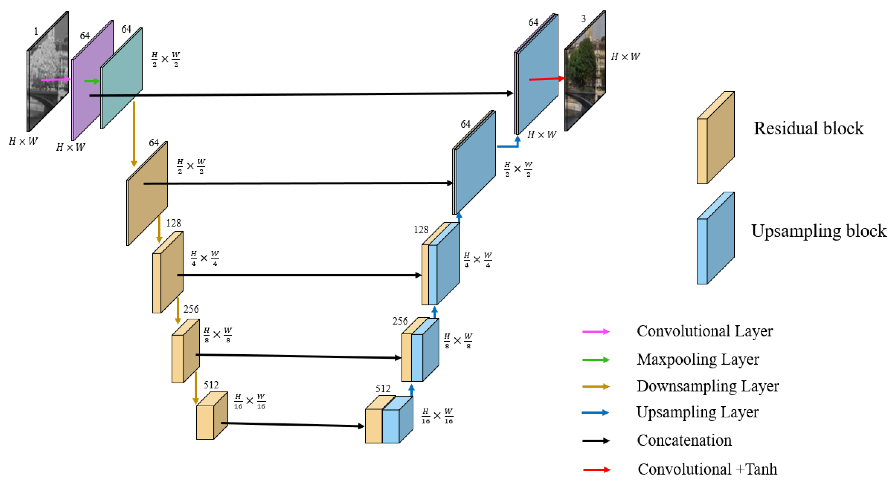
The structure of ACD is shown in Figure 3. The left half is the residual encoder and the right half is the decoder. Different from SCD, in the encoder, we add residual blocks to the downsampling layer to improve the feature extraction ability of the encoder, while the decoder uses only an upsampling layer. The main feature of encoder is the short skip connections between the residual blocks, so that the output of the previous block combined with the output of the current block is used as the input of the next block. The purpose of such a structure is to improve the feature extraction ability of the encoder by allowing the information to enter deeper into the model and learn more non-redundant information. The decoder is consistent with the decoder in the original UNet. Meanwhile, an improved encoder is proposed based on raw LinkNet. Specifically, one less downsampling layer than LinkNet is used in the encoder and bilinear interpolation is used for upsampling instead of deconvolution. The skip connection is used between the encoder and the decoder.
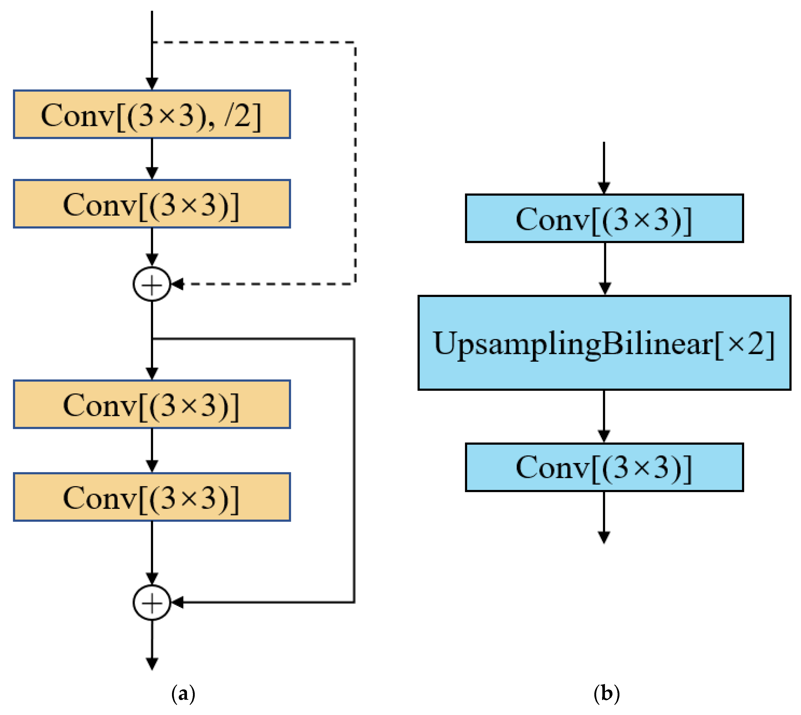
The initial block of the encoder is a convolution block with a kernel size of 7 × 7 and a stride of 1. Behind the initial convolution block, a max-pooling with a stride of 2 is used to downsample the input images. The later portion of the encoder consists of 4 residual blocks. Each residual block is shown in detail in Figure 4a. Here, Conv means convolution and /2 means downsampling by a convolution with stride of 2. In addition, for encoder training, we adopt transfer learning, initializing the encoder with ImageNet [33] pretrained weights.
The decoder consists of 6 convolution blocks; the first 5 convolution blocks remain the same as the original UNet, which is computationally efficient. Each block firstly upsamples the input feature maps by bilinear interpolation then concatenates with the cropped feature maps from the residual encoder. Layers within these decoder blocks are shown in detail in Figure 4b. * 2 means upsampling by a factor of 2, which is achieved by bilinear interpolation. Finally, behind the last upsampling block, a 1 × 1 convolution followed with a tanh(x) activation layer, which is suitable for generating images [26], is used to generate the final RGB image. Moreover, we use batch normalization between each convolutional layer, which is followed by ReLU non-linearity.

3.1.2. GLFFNet

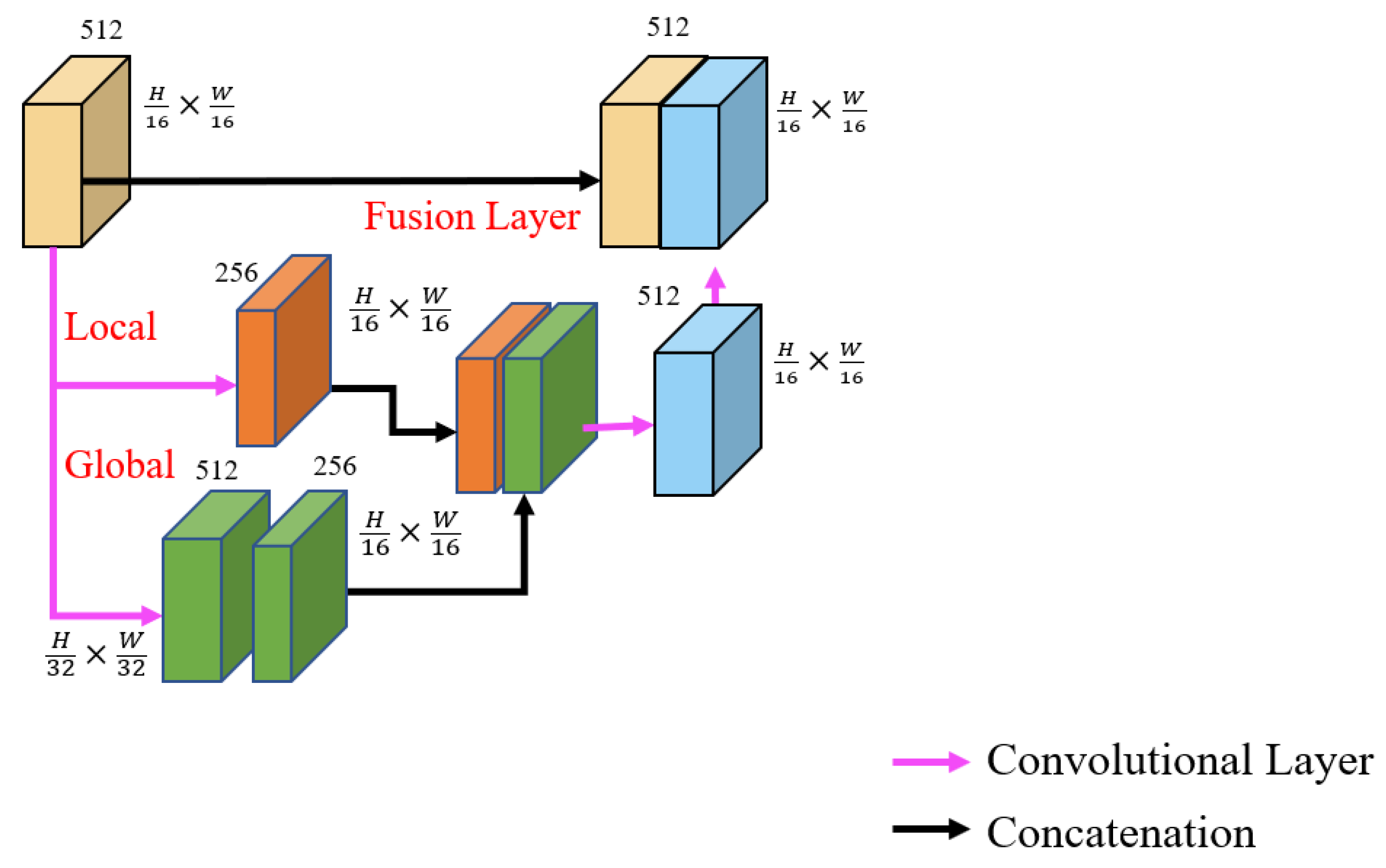
For NIR image colorization, the prediction of subtle color information in the local image plays an important role to generate color information in three channels. Therefore, we embed GLFFNet between the encoder and decoder to reduce the information loss in the pooling layer of the encoder and improve the prediction of the subtle color of the image. The GLFFNet structure is shown in Figure 5.
The local feature network is a convolution block with a kernel of size 3 × 3 and a stride of 1. The number of channels is halved to 256 while keeping the image size unchanged. The global feature network consists of two convolution blocks; the first convolution block is used to halve the image size by setting the stride to 2 and the second convolution block is used to halve the number of channels to 256. Finally, the global and local features are spliced in the two dimensions of length and width through the fusion layer, then a 512-dimensional fused feature map is obtained.

3.1.3. Loss Function

Mapping an NIR image to an RGB image is a regression problem and predicting an RGB image can be expressed by Equation (1) as:
Y = F X
where X is the input NIR image, Y represents the predicted RGB image, and F is our ColorNet.
Our goal is to minimize the difference in intensity of the pixels between the predicted RGB image and ground truth. The mathematical expression is shown in Equation (2):
F = arg min ( Y ,   Y )
where Y represents the ground truth.
In the face of different target tasks, it is necessary to choose the most appropriate loss function to achieve the best penalty network effect. The network regression is trained to output an RGB image, which is similar to the ground truth, and the Euclidean distance calculation is more suitable, so L2 regression is used as the loss function. Therefore, Equation (2) can be expressed by the following Equation:
F = arg min ( Y Y 2 )
For a certain pixel, the loss is defined in Equation (4):
l o s s c o l o r = Y Y 2
Subsequently, for a batch of images, the loss function is defined in Equation (5):
L o s s c o l o r ( F ( X ; θ ) , Y ) = ( b B h , w H , W l o s s c o l o r ( F ( X ; θ ) b , h , w , Y b , h , w ) )
where X R H × W × 1 × B is a set of one channel NIR images. Y R H × W × 3 × B represents a set of the three-channel ground truth. B represents the number of images in a batch. F ( X ; θ ) b , h , w represents the output color images of ColorNet. θ represents the hyperparameters of the network. The sum of the losses for each batch is taken as the final total loss.

3.2. BFWLS

Since the useful details of the image can be enhanced by fusion of RGB and NIR images [34], the BFWLS is proposed to fuse the rich detail information of the input NIR image into the initial colorized RGB image to obtain optimized output color image.
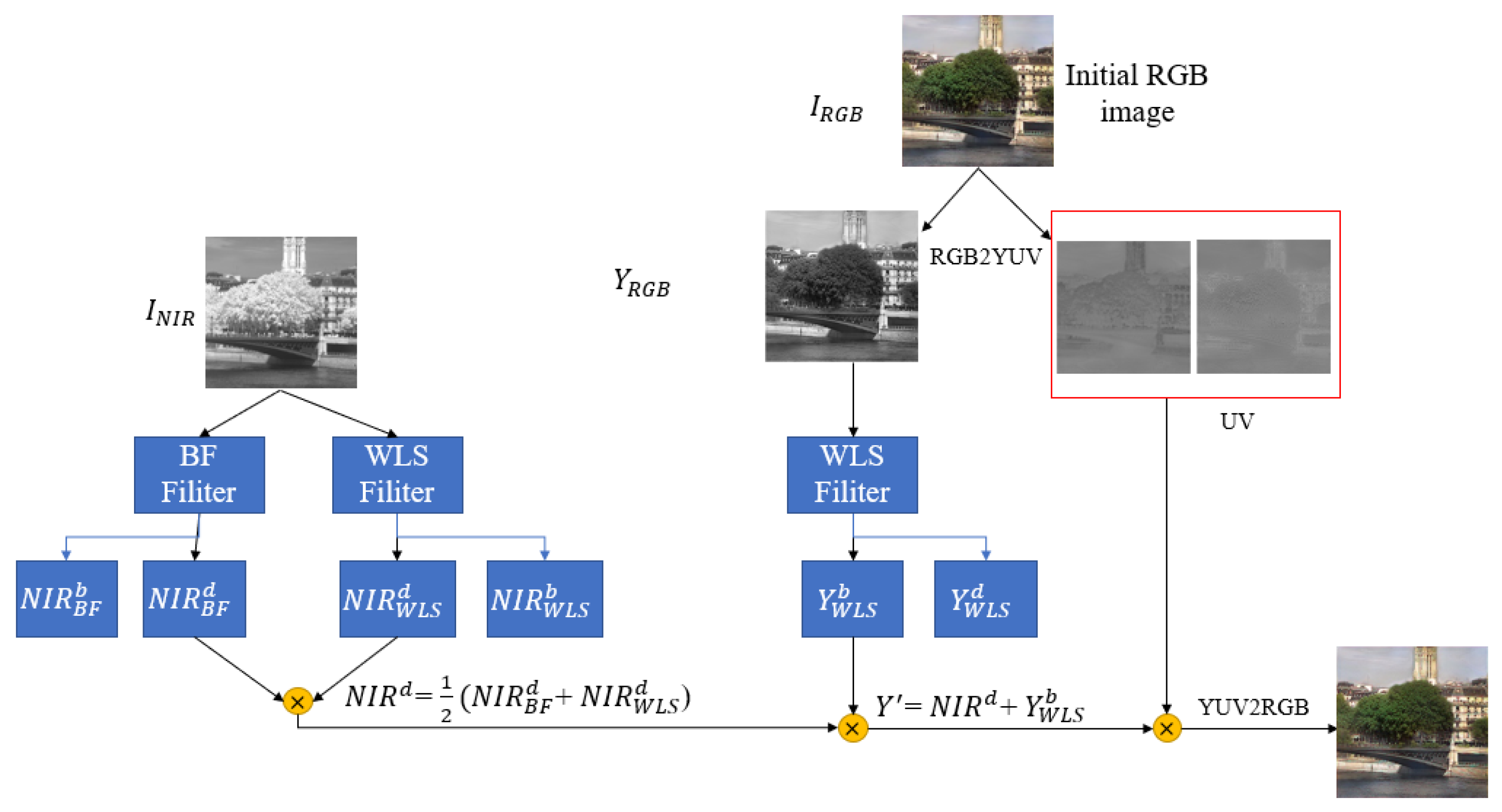
The fusion process is shown in Figure 6. In BFWLS, BF can preserve the image content structure well and WLS is used to preserve shading distribution of reference information. In order to ensure the color fidelity of output image of the ColorNet, the initial RGB image is decomposed into luminance and chrominance and a new luminance layer is restructured by fusing the luminance of the RGB image with the NIR image. In our method, the luminance layer of RGB image is derived from the YUV color space, because it is suitable for situations where the luminance decreases significantly from RGB to NIR images [7].
The BFWLS fusion consists of three steps. In the first step, the NIR image is decomposed into base and detail images by BF and WLS filters, respectively. The base image refers to the filtered smooth image. The detail images are obtained by subtracting the base image from NIR image. The solution process of detail images is shown in Equations (6) and (7):
N I R B F d = N I R N I R B F b
N I R W L S d = N I R N I R W L S b
where the superscript d indicates the detail image and the superscript b indicates the base image. N I R B F b represents the NIR base image after BF filtering, N I R W L S b represents the NIR base image after WLS filtering, N I R B F d represents the NIR detail image after BF filtering, and N I R W L S d represents the NIR detail image after WLS filtering. Finally, the average values of the detail-WLS and detail-BF that are extracted from the NIR image are retained. The final detail layer is obtained by Equation (8):
N I R d = 1 2 ( N I R B F d + N I R W L S d )
In the second step, color space is transformed from RGB to YUV and then WLS filtering is performed on the Y channel. The fused detail layer N I R d obtained by the first step and the base-WLS of the Y channel are combined to obtain a new luminance layer. The mathematical expression is shown in Equation (9):
Y = N I R d + Y W L S b
where Y W L S b represents the Y channel base image after WLS filtering and Y represents the final luminance layer.
In the third step, the new luminance layer obtained by the second step and chrominance channel UV are combined and transform to RGB color space to obtain the final fused RGB image.

4. Experiments and Analysis

Brown and his cooperators proposed an RGB-NIR scene dataset [35], which contains 477 NIR images and 477 corresponding RGB images with image sizes of 1024 × 680 pixels and this dataset was captured from nine categories of scenes. Thus, 763 pairs of NIR and RGB images were generated by splitting up images and then each image size is unified to 480 × 480 pixels. As such, 57 pairs of images were randomly selected as the test set and the rest of the image pairs were used as the training set. It should be noted that image pairs in the dataset are correctly registered by using a global calibration method, so that a pixel-to-pixel correspondence is guaranteed for quantitative and qualitative evaluation.
We train the network with an NVIDIA TITAN RTX GPU and use stochastic Adam optimizer, which prevents overfitting and leads to convergence faster [36]. Meanwhile, we save the optimal model within 300 epochs. The hyper-parameters were tuned during the training stage as follows: initial learning rate 1 × 10 4 , β1 = 0.9, β2 = 0.999, ϵ = 1 × 10 8 , leak ReLU 0.2, batch size 16.

4.1. Main Experiment

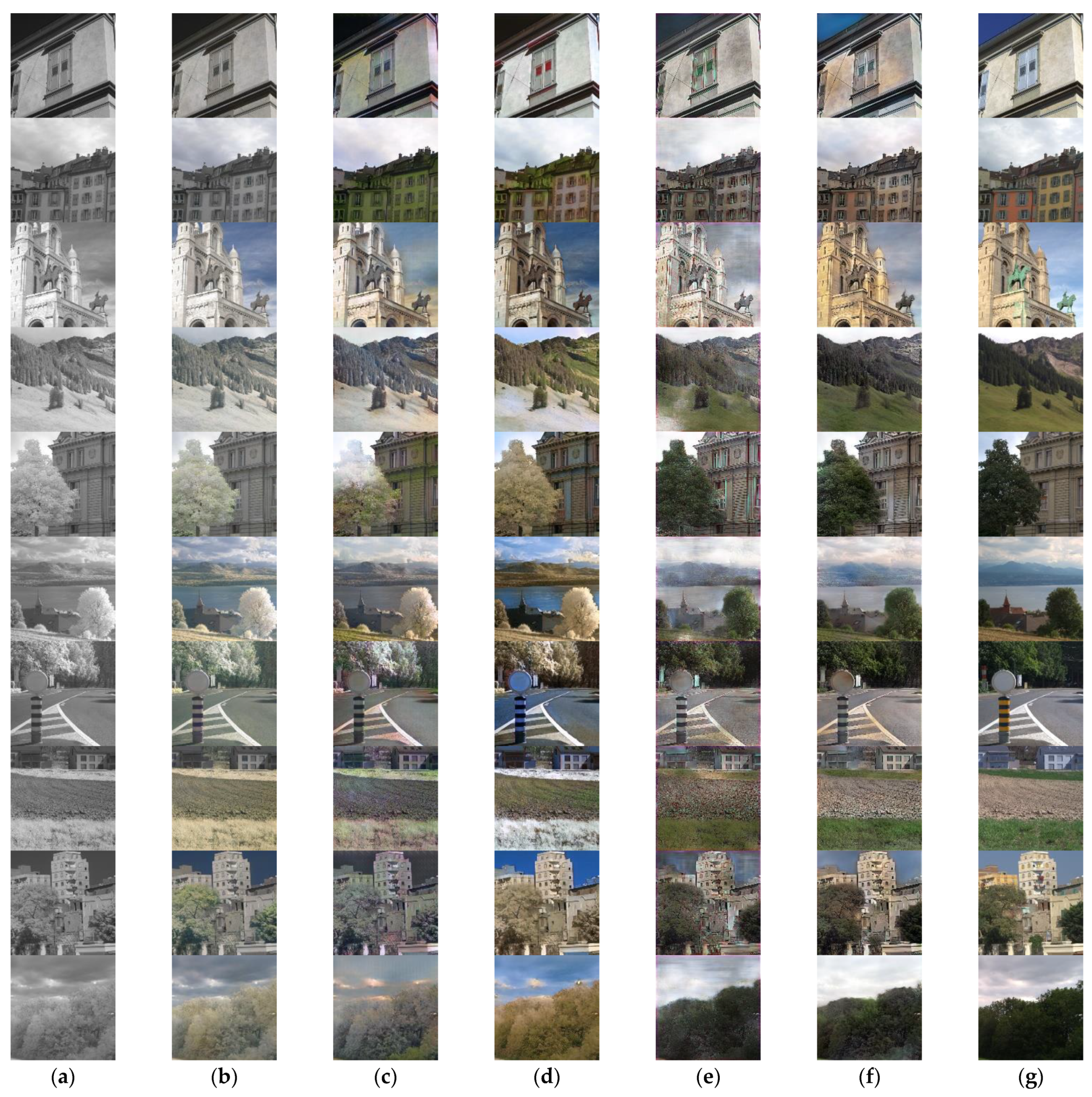
In order to verify the effectiveness of the proposed method, we execute some adopted methods, including the DeOldify method based on deep learning [37], the CycleGAN method using UNet as the generator [30], the CycleGAN method using ResNet as the generator [31], and the S-Net method based on UNet [6]. The corresponding results are plotted in Figure 7.
As shown in Figure 7, satisfactory results are obtained. First, our method is better at coloring vegetation and making it closer to the actual image in the scene, while the DeOldify and CycleGAN_UNet methods did not estimate the correct luminance information, resulting in vegetation in the NIR image being “transparent”. Compared with CycleGAN_UNet, the color of vegetation and sky of CycleGAN_ResNet is improved well, but there are some color errors, such as the street signs and roads in the seventh row are painted blue and the mud in the eighth row is painted green. Second, compared to results from the S-Net method, our method contains more detailed texture information, such as the sky in the sixth row and trees and buildings in ninth row have clearer textures. Third, the building generated is with a reasonable color rather than being gray, like those obtained by DeOldify, or being uneven, like those obtained by CycleGAN_UNet, CycleGAN_ResNet, and S-Net. Finally, although the color of our reconstructed image cannot be completely consistent with that of the original image, our method can obtain an RGB image with more natural appearance. In the examples of images in the fifth and tenth rows, the ground truth itself has a less obvious color, but the color of the tree becomes clearer and brighter after coloring by our method.
For quantitative evaluations, three evaluation metrics are used, including PSNR (Peak Signal to Noise Ratio) [38], MAE (Mean Absolute Error), and SSIM (structural similarity index) [39].
PSNR is an evaluation index to measure image quality. The higher the value, the better the image quality. It is defined by mean square error (MSE).
P S N R = 10 × l o g 10 ( ( 2 n 1 ) 2 M S E )
where n is the bit depth of image and MSE is represented by the following formula:
M S E = 1 H × W i = 1 H j = 1 W ( Y ( i , j ) Y ( i , j ) ) 2
where H and W represent the height and width of images, respectively, Y represents the ground truth, Y represents the predicted RGB image, and (i,j) represents the pixel position.
MAE is used to calculate the pixel-level mean absolute error between the predicted RGB image and the ground truth and the formula can be expressed as:
M A E = 1 n i n | Y i Y i |
where n is the number of pixels.
SSIM measures image similarity from three aspects: brightness, contrast, and structure, respectively. The SSIM is defined as:
S S I M = l ( Y , Y ) × c ( Y , Y ) × s ( Y , Y )
where
l ( Y , Y ) = 2 μ Y μ Y + C 1 μ Y 2 + μ Y 2 + C 1 c ( Y , Y ) = 2 σ Y σ Y + C 2 σ Y 2 + σ Y 2 + C 2 s ( Y , Y ) = σ Y Y + C 3 σ Y σ Y + C 3
where μ Y , μ Y represent the mean of images Y and Y , respectively, σ Y ,   σ Y represent the variance in images Y and Y , respectively, and σ Y Y represents the covariance of images Y and Y . C 1 ,   C 2 , C 3 are constants, C 1 is generally equal to 6.5025, C 2 is generally equal to 58.5225, and C 3 is generally equal to 29.26125.
In addition to the above-mentioned general evaluation metrics for images, we use S-CIELAB [40] and LPIPS [41] indicators to evaluate image color specifically. The specific operation is to transfer the color image to LAB space and only evaluate the color information AB.
The S-CIELAB is a subjective measure, designed for measuring the image quality from a human perspective. The chromatic aberration Δ E is defined as:
Δ E = i = 1 H j = 1 W ( A i , j A i , j ) 2 + ( B i , j B i , j ) 2 2
where A i , j , B i , j represent the A channel and B channel of the ground truth, respectively, and A i , j ,   B i , j represent the A channel and B channel of the predicted RGB image.
LPIPS is used to measure the perceptual similarity of the predicted RGB image and the ground truth. The difference in color perception ΔD is defined as:
Δ D ( A B , A B ) = l 1 H l W l h , w w l ( a b ^ h , w l a b ^ h , w l ) 2 2
where a b ^ h , w l represents the ab channel of the feature stack extracted from the l t h layer. The vector w l is used to scale the number of active channels.
Table 1 shows the average metrics values of different methods with 57 randomly chosen test images. It follows from this table that the MAE in our method is the smallest and PSNR is the biggest. Only SSIM is slightly lower than the DeOldify method. The main reason could be that the amount of NIR image information used is obviously higher than ours, but its color reconstruction results are the worst from the visual evaluation. Furthermore, our method also performs the best on both S-CIELAB and LPIPS metrics. In summary, the proposed method achieving NIR colorization is obviously superior to the existing methods.

4.2. Ablation Studies

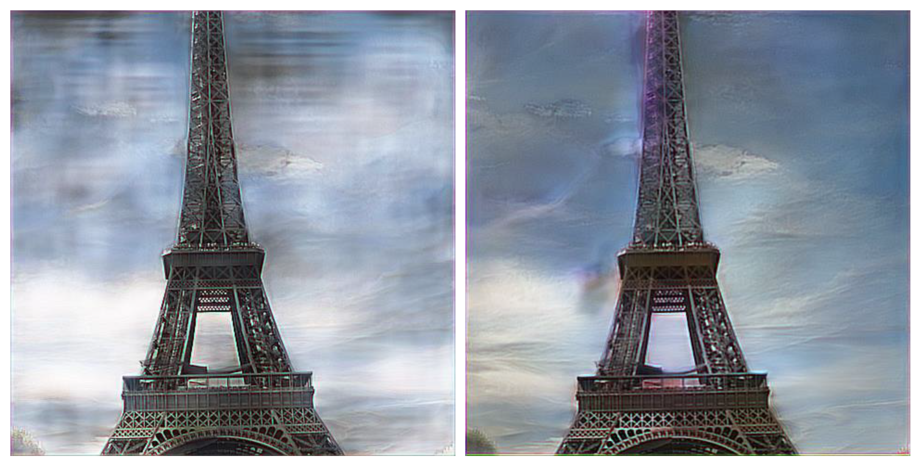
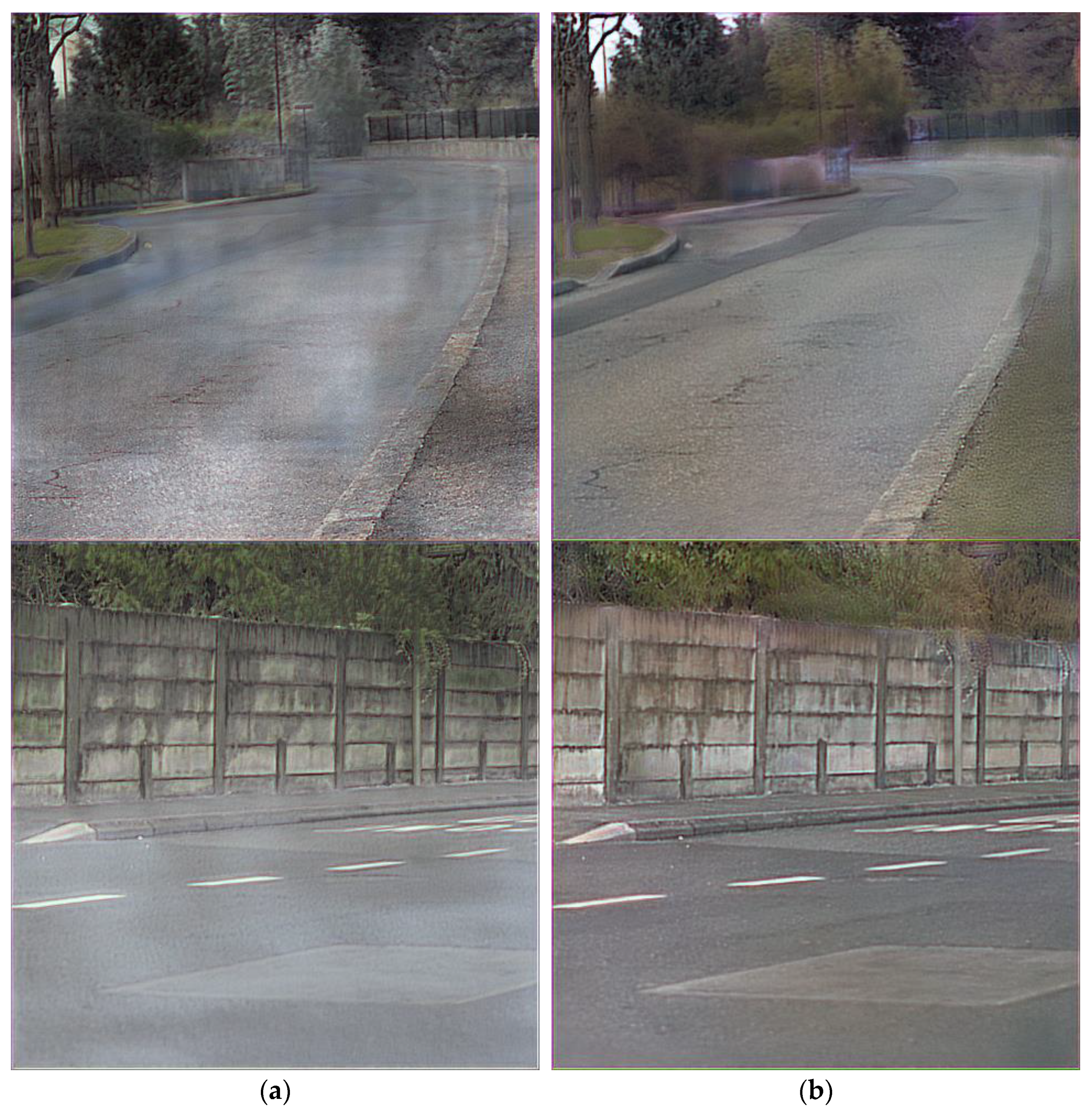
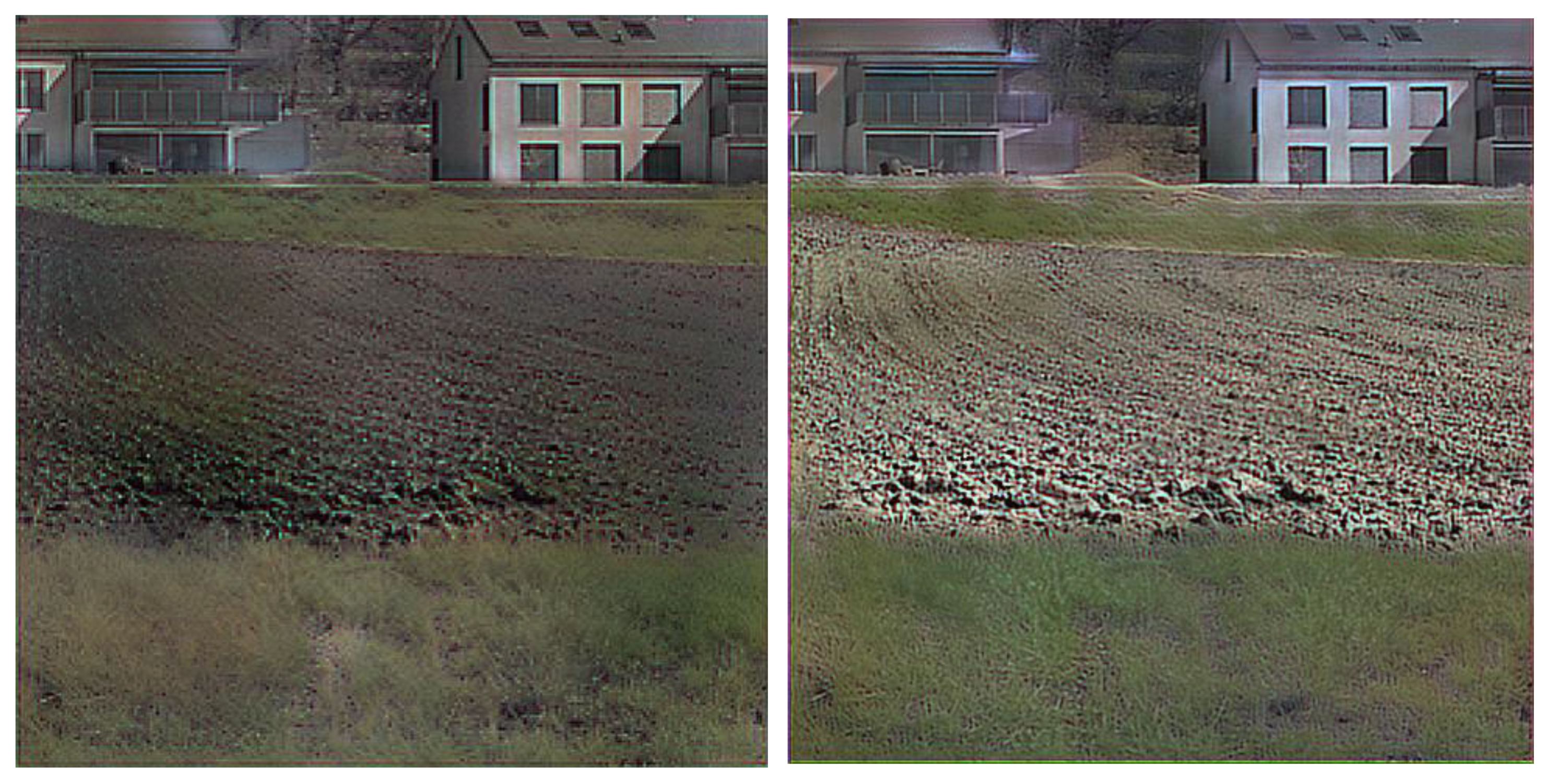
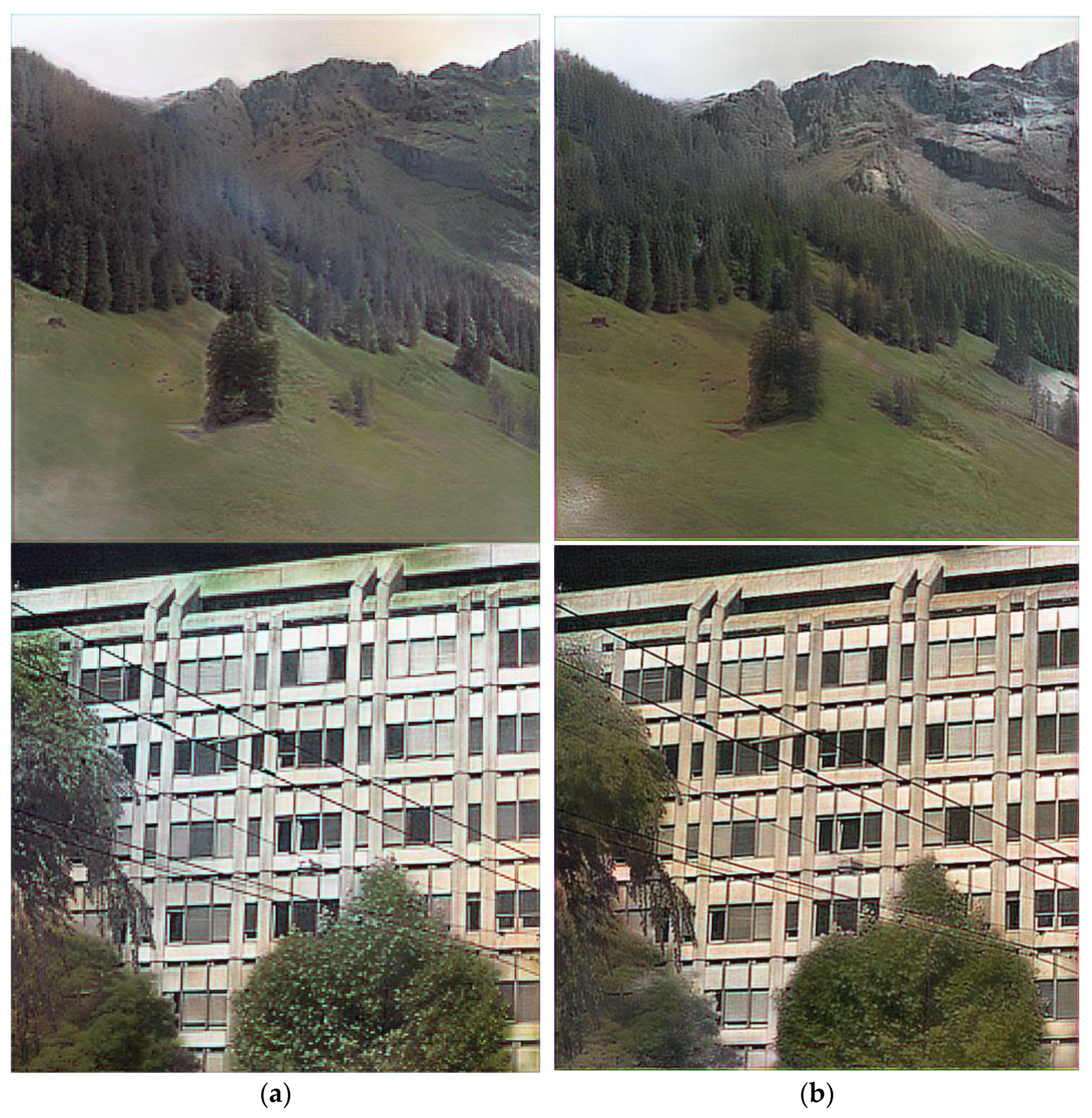
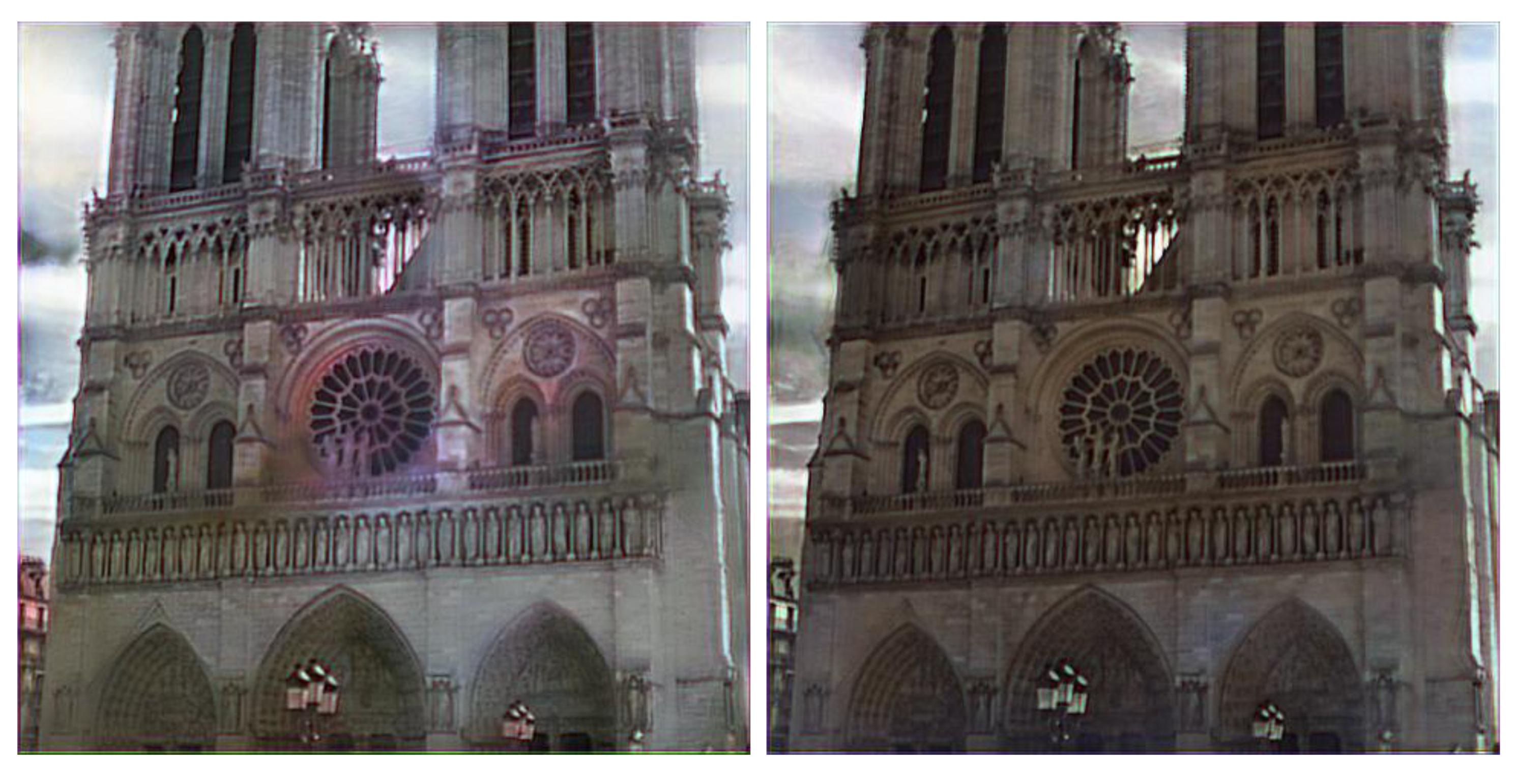
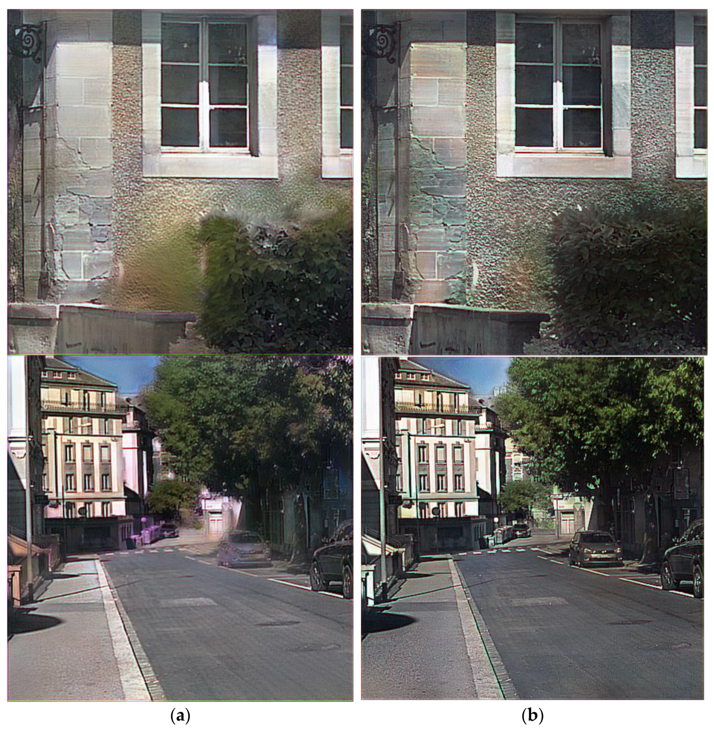
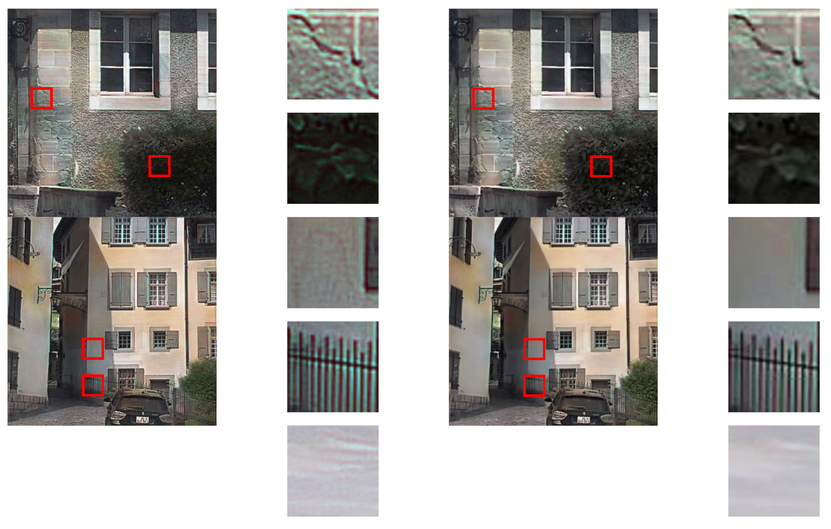
We conducted three ablation studies to analyze the contribution of each module: (1) ACD only; (2) LinkNet; (3) ACD and GLFFNet, i.e., ColorNet; (4) ColorNet and BFWLS. The ablations are carried out on the same dataset as the main experiments. Figure 8, Figure 9, Figure 10 and Figure 11 show the effect of each module on color or detail performance, respectively. The quantitative comparison results are shown in Table 2.
Figure 8 shows that ACD can improve the phenomenon of partial color error and texture blur of SCD. For example, the textures of vegetation and buildings are clearer and the color of the road and sky is normal. At the same time, it follows from Table 2 that ACD has the most significant improvement in PSNR, by 0.9095. Furthermore, compared to LinkNet, ACD is more accurate in local colorization, as shown in Figure 9. In terms of qualitative metrics, all metrics of ACD are better than LinkNet. The effect of GLFFNet is clearly shown in Figure 10. Without GLFFNet, the edge color spills in vegetation and the color shows unevenly in buildings. MAE and PSNR slightly improved from the qualitative analysis and LPIPS is the best. The function of BFWLS is shown in Figure 11. Comparing the results with and without this module, we can draw the conclusion that BFWLS can not only smooth the artifact of the picture, but also enhance the texture of the vegetation. The introduction of the BFWLS has a greater impact on PSNR and SSIM, achieving a 0.7978 gain in PSNR and 0.0974 gain in SSIM. Moreover, S-CIELAB lowered by 1.1651.

5. Conclusions

This paper proposed a novel NIR colorization method using ACD and pixel-level fusion. Our method can generate high-quality RGB images in different natural scenes. We compare classical colorization methods based on a common dataset and the experimental results show that the proposed method provides better images in enhancing textures and coloring naturally. It is worth mentioning that our model is more suitable for training and colorization of large-size NIR images, so it has greater practical application value. Furthermore, we conducted ablation studies to demonstrate the contributions of the three modules proposed in this paper. From the result, we can conclude that ACD enhances the colorization accuracy and texture sharpness, GLFFNet improves the color overflow and uneven color, and BFWLS fusion enables us to obtain more delicate coloring results. Under the condition of ensuring the coloring quality, future work will focus on the lightweight colorization of unpaired NIR-RGB images to address the lack of existing paired NIR-RGB datasets.

Author Contributions

Conceptualization, X.M. and W.H.; methodology, X.M. and W.H.; software, X.M.; validation, X.M. and R.H.; project administration, X.L.; resources, X.L.; writing—original draft preparation, X.M.; writing—review and editing, W.H. All authors have read and agreed to the published version of the manuscript.

Funding

This research was funded by the Innovation Action Plan of Shanghai Science and Technology Commission in 2022, grant number 21511102605.

Institutional Review Board Statement

Not applicable.

Informed Consent Statement

Not applicable.

Data Availability Statement

Not applicable.

Conflicts of Interest

The authors declare no conflict of interest.

References

  1. Luo, Y.; Remillard, J.; Hoetzer, D. Pedestrian Detection in Near-Infrared Night Vision System. In Proceedings of the 2010 IEEE Intelligent Vehicles Symposium, IEEE, La Jolla, CA, USA, 21–24 June 2010; pp. 51–58. [Google Scholar]
  2. Ariff, M.F.M.; Majid, Z.; Setan, H.; Chong, A.K.-F. Near-infrared camera for night surveillance applications. Geoinf. Sci. J. 2010, 10, 38–48. [Google Scholar]
  3. Vance, C.K.; Tolleson, D.R.; Kinoshita, K.; Rodriguez, J.; Foley, W.J. Near infrared spectroscopy in wildlife and biodiversity. J. Near Infrared Spectrosc. 2016, 24, 1–25. [Google Scholar] [CrossRef]
  4. Aimin, Z. Denoising and fusion method of night vision image based on wavelet transform. Electron. Meas. Technol. 2015, 38, 38–40. [Google Scholar]
  5. Limmer, M.; Lensch, H.P. Infrared Colorization Using Deep Convolutional Neural Networks. In Proceedings of the 2016 15th IEEE International Conference on Machine Learning and Applications (ICMLA), IEEE, Anaheim, CA, USA, 18–20 December 2016; pp. 61–68. [Google Scholar]
  6. Dong, Z.; Kamata, S.-I.; Breckon, T.P. Infrared Image Colorization Using a S-Shape Network. In Proceedings of the 2018 25th IEEE International Conference on Image Processing (ICIP), IEEE, Athens, Greece, 7–10 October 2018; pp. 2242–2246. [Google Scholar]
  7. Fredembach, C.; Süsstrunk, S. Colouring the Near-Infrared. In Proceedings of the Color and Imaging Conference, Society for Imaging Science and Technology, Terrassa, Spain, 9–13 June 2008; pp. 176–182. [Google Scholar]
  8. Chitu, M. Near-Infrared Colorization using Neural Networks for In-Cabin Enhanced Video Conferencing. In Proceedings of the 2021 International Aegean Conference on Electrical Machines and Power Electronics (ACEMP) & 2021 International Conference on Optimization of Electrical and Electronic Equipment (OPTIM), IEEE, Brasov, Romania, 2–3 September 2021; pp. 493–498. [Google Scholar]
  9. Ronneberger, O.; Fischer, P.; Brox, T. U-Net: Convolutional Networks for Biomedical Image Segmentation. In Proceedings of the International Conference on Medical Image Computing and Computer-Assisted Intervention, Munich, Germany, 5–9 October 2015; Springer: Berlin/Heidelberg, Germany, 2015; pp. 234–241. [Google Scholar]
  10. Sun, T.; Jung, C.; Fu, Q.; Han, Q. Nir to rgb domain translation using asymmetric cycle generative adversarial networks. IEEE Access 2019, 7, 112459–112469. [Google Scholar] [CrossRef]
  11. Chaurasia, A.; Culurciello, E. Linknet: Exploiting Encoder Representations for Efficient Semantic Segmentation. In Proceedings of the 2017 IEEE Visual Communications and Image Processing (VCIP), IEEE, St. Petersburg, FL, USA, 10–13 December 2017; pp. 1–4. [Google Scholar]
  12. He, K.; Zhang, X.; Ren, S.; Sun, J. Deep Residual Learning for Image Recognition. In Proceedings of the IEEE Conference on Computer Vision and Pattern Recognition, Las Vegas, NV, USA, 27–30 June 2016; pp. 770–778. [Google Scholar]
  13. Zhou, L.; Zhang, C.; Wu, M. D-LinkNet: LinkNet with Pretrained Encoder and Dilated Convolution for High Resolution Satellite Imagery Road Extraction. In Proceedings of the IEEE Conference on Computer Vision and Pattern Recognition Workshops, Salt Lake City, UT, USA, 18–22 June 2018; pp. 182–186. [Google Scholar]
  14. Liang, W.; Derui, D.; Guoliang, W. An improved DualGAN for near-infrared image colorization. Infrared Phys. Technol. 2021, 116, 103764. [Google Scholar]
  15. Levin, A.; Lischinski, D.; Weiss, Y. Colorization using optimization. In ACM SIGGRAPH 2004 Papers; Association for Computing Machinery: New York, NY, USA, 2004; pp. 689–694. [Google Scholar]
  16. Yatziv, L.; Sapiro, G. Fast image and video colorization using chrominance blending. IEEE Trans. Image Process. 2006, 15, 1120–1129. [Google Scholar] [CrossRef] [Green Version]
  17. Zhang, R.; Zhu, J.-Y.; Isola, P.; Geng, X.; Lin, A.S.; Yu, T.; Efros, A.A. Real-time user-guided image colorization with learned deep priors. arXiv 2017, preprint. arXiv:1705.02999. [Google Scholar] [CrossRef] [Green Version]
  18. Welsh, T.; Ashikhmin, M.; Mueller, K. Transferring Color to Greyscale Images. In Proceedings of the 29th Annual Conference on Computer Graphics and Interactive Techniques, San Antonio, TX, USA, 23–26 July 2002; pp. 277–280. [Google Scholar]
  19. Liu, X.; Wan, L.; Qu, Y.; Wong, T.-T.; Lin, S.; Leung, C.-S.; Heng, P.-A. Intrinsic colorization. In ACM SIGGRAPH Asia 2008 Papers; Association for Computing Machinery: New York, NY, USA, 2008; pp. 1–9. [Google Scholar]
  20. Ironi, R.; Cohen-Or, D.; Lischinski, D. Colorization by Example. Render. Tech. 2005, 29, 201–210. [Google Scholar]
  21. Charpiat, G.; Hofmann, M.; Schölkopf, B. Automatic Image Colorization via Multimodal Predictions. In Proceedings of the European Conference on Computer Vision, Marseille, France, 12–18 October 2008; Springer: Berlin/Heidelberg, Germany, 2008; pp. 126–139. [Google Scholar]
  22. Gupta, R.K.; Chia, A.Y.-S.; Rajan, D.; Ng, E.S.; Zhiyong, H. Image Colorization Using Similar Images. In Proceedings of the 20th ACM International Conference on Multimedia, Bali, Indonesia, 3–5 December 2012; pp. 369–378. [Google Scholar]
  23. Chia, A.Y.-S.; Zhuo, S.; Gupta, R.K.; Tai, Y.-W.; Cho, S.-Y.; Tan, P.; Lin, S. Semantic colorization with internet images. ACM Trans. Graph. 2011, 30, 1–8. [Google Scholar] [CrossRef]
  24. Iizuka, S.; Simo-Serra, E.; Ishikawa, H. Let there be color! Joint end-to-end learning of global and local image priors for automatic image colorization with simultaneous classification. ACM Trans. Graph. 2016, 35, 1–11. [Google Scholar] [CrossRef]
  25. Vitoria, P.; Raad, L.; Ballester, C. Chromagan: Adversarial picture colorization with semantic class distribution. In Proceedings of the IEEE/CVF Winter Conference on Applications of Computer Vision, Snowmass Village, CO, USA, 2–5 March 2020; pp. 2445–2454. [Google Scholar]
  26. Zhang, R.; Isola, P.; Efros, A.A. Colorful Image Colorization. In Proceedings of the European Conference on Computer Vision, Amsterdam, The Netherlands, 11–14 October 2016; Springer: Berlin/Heidelberg, Germany, 2016; pp. 649–666. [Google Scholar]
  27. Suárez, P.L.; Sappa, A.D.; Vintimilla, B.X. Learning to Colorize Infrared Images. In Proceedings of the International Conference on Practical Applications of Agents and Multi-Agent Systems, Salamanca, Spain, 6–8 October 2017; Springer: Berlin/Heidelberg, Germany, 2017; pp. 164–172. [Google Scholar]
  28. Suárez, P.L.; Sappa, A.D.; Vintimilla, B.X. Infrared Image Colorization Based on a Triplet Dcgan Architecture. In Proceedings of the IEEE Conference on Computer Vision and Pattern Recognition Workshops, Honolulu, HI, USA, 21–26 July 2017; pp. 18–23. [Google Scholar]
  29. Kim, H.; Kim, J.; Kim, J. Infrared Image Colorization Network Using Variational AutoEncoder. In Proceedings of the 36th International Technical Conference on Circuits/Systems, Computers and Communications (ITC-CSCC), IEEE, Jeju-si, Korea, 27–30 June 2021; pp. 1–4. [Google Scholar]
  30. Mehri, A.; Sappa, A.D. Colorizing Near Infrared Images through a Cyclic Adversarial Approach of Unpaired Samples. In Proceedings of the IEEE/CVF Conference on Computer Vision and Pattern Recognition Workshops, Long Beach, CA, USA, 16–17 June 2019. [Google Scholar]
  31. Zhu, J.-Y.; Park, T.; Isola, P.; Efros, A.A. Unpaired Image-to-Image Translation Using Cycle-Consistent Adversarial Networks. In Proceedings of the IEEE International Conference on Computer Vision, Venice, Italy, 22–29 October 2017; pp. 2223–2232. [Google Scholar]
  32. Yang, Z.; Chen, Z. Learning from Paired and Unpaired Data: Alternately Trained CycleGAN for Near Infrared Image Colorization. In Proceedings of the 2020 IEEE International Conference on Visual Communications and Image Processing (VCIP), IEEE, Macau, China, 1–4 December 2020; pp. 467–470. [Google Scholar]
  33. Deng, J.; Dong, W.; Socher, R.; Li, L.-J.; Li, K.; Fei-Fei, L. Imagenet: A Large-Scale Hierarchical Image Database. In Proceedings of the 2009 IEEE Conference on Computer Vision and Pattern Recognition, IEEE, Miami, FL, USA, 20–25 June 2009; pp. 248–255. [Google Scholar]
  34. Sharma, V.; Hardeberg, J.Y.; George, S. RGB-NIR Image Enhancement by Fusing Bilateral and Weighted Least Squares Filters. J. Imaging Sci. Technol. 2017, 61, 40409-1–40409-9. [Google Scholar] [CrossRef]
  35. Brown, M.; Süsstrunk, S. Multi-Spectral SIFT for Scene Category Recognition. In Proceedings of the CVPR 2011, IEEE, Colorado Springs, CO, USA, 20–25 June 2011; pp. 177–184. [Google Scholar]
  36. Kingma, D.P.; Ba, J. Adam: A method for stochastic optimization. arXiv 2014, preprint. arXiv:1412.6980. [Google Scholar]
  37. Antic, J. A Deep Learning Based Project for Colorizing and Restoring Old Images. 2018. Available online: https://github.com/jantic/DeOldifyn (accessed on 15 March 2022).
  38. Hore, A.; Ziou, D. Image Quality Metrics: PSNR vs. SSIM. In Proceedings of the 2010 20th International Conference on Pattern Recognition, IEEE, Istanbul, Turkey, 23–26 August 2010; pp. 2366–2369. [Google Scholar]
  39. Wang, Z.; Bovik, A.C.; Sheikh, H.R.; Simoncelli, E.P. Image quality assessment: From error visibility to structural similarity. IEEE Trans. Image Process. 2004, 13, 600–612. [Google Scholar] [CrossRef]
  40. Zhang, X.; Wandell, B.A. A Spatial Extension of CIELAB for Digital Color Image Reproduction. In Proceedings of the SID International Symposium Digest of Technical Papers, San Diego, CA, USA, 12–17 May 1996; Citeseer: Princeton, NJ, USA, 1996; pp. 731–734. [Google Scholar]
  41. Zhang, R.; Isola, P.; Efros, A.A.; Shechtman, E.; Wang, O. The Unreasonable Effectiveness of Deep Features as a Perceptual Metric. In Proceedings of the IEEE Conference on Computer Vision and Pattern Recognition, Salt Lake City, UT, USA, 18–22 June 2018; pp. 586–595. [Google Scholar]
Figure 1. A block diagram overview of NIR colorization method.
Applsci 12 10087 g001
Figure 2. Overview of our ColorNet structure.
Applsci 12 10087 g002
Figure 3. ACD structure diagram.
Applsci 12 10087 g003
Figure 4. Details of layers within blocks: (a) layers within these residual blocks; (b) layers within these decoder blocks.
Applsci 12 10087 g004
Figure 5. GLFFNet structure diagram.
Applsci 12 10087 g005
Figure 6. The flow chart of BFWLS fusion.
Applsci 12 10087 g006
Figure 7. Visual comparison of different methods: (a) input NIR images; (b) DeOldify via deep learning [37]; (c) CycleGAN_UNet [30]; (d) CycleGAN_ResNet [31]; (e) S-Net [6]; (f) our method; and (g) corresponding RGB images.
Applsci 12 10087 g007
Figure 8. Color performance comparison of different modules: (a) symmetric codec (SCD) only; (b) asymmetric codec (ACD) only.
Applsci 12 10087 g008aApplsci 12 10087 g008b
Figure 9. Color performance comparison of different modules: (a) LinkNet; (b) asymmetric codec (ACD) only.
Applsci 12 10087 g009aApplsci 12 10087 g009b
Figure 10. Color performance comparison of different modules: (a) asymmetric codec (ACD) only; (b) ACD combined with GLFFNet (ColorNet).
Applsci 12 10087 g010aApplsci 12 10087 g010b
Figure 11. Color performance comparison of different modules: (a) ColorNet; (b) ColorNet combined with BFWLS.
Applsci 12 10087 g011aApplsci 12 10087 g011b
Table 1. Average values of quality metrics for 57 colored NIR images. The best performing metrics are highlighted in bold format.
MethodsMAEPSNRSSIMS-CIELABLPIPS
DeOldify [37]0.163114.77150.64488.92500.1516
CycleGAN_UNet [30]0.155914.88070.61419.48620.1519
CycleGAN_ResNet [31]0.101415.55180.61539.63040.1485
S-Net [6]0.113916.58150.520510.12540.1278
Ours0.093918.44210.63638.49120.1225
Table 2. Ablation experiments of various modules. The best performing metrics are highlighted in bold format.
ModulesMAEPSNRSSIMS-CIELABLPIPS
SCD only
LinkNet
0.1139
0.1072
16.5815
17.1252
0.5205
0.5368
10.1254
9.9567
0.1278
0.1337
ACD only0.110717.49100.54859.89600.1254
ACD+GLFFNet (ColorNet)0.099317.64430.53899.65630.1117
ColorNet + BFWLS(Ours)0.093918.44210.63638.49120.1225
Publisher’s Note: MDPI stays neutral with regard to jurisdictional claims in published maps and institutional affiliations.