Abstract
In this paper, we proposed a high-efficiency 2.45 GHz and 5.8 GHz dual-band rectenna for wireless energy harvesting (WEH). First, a dual-band dielectric resonant antenna (DRA) was designed. A 4-element DRA array was further developed using a compact feeding network. The measured gains of the DRA array were 5.5 dBi at 2.45 GHz and 12.9 dBi at 5.8 GHz. Then, a new type of impedance regulation stub (IRS) was introduced that significantly improved the conversion efficiency of the rectenna. The result showed that the conversion efficiency of the rectifier was 66% and 62% at 2.45 GHz and 5.8 GHz, respectively, when the input power level was 10 dBm. Furthermore, the proposed rectenna was validated to activate a standard BQ25504 DC-to-DC boost converter and charge a supercapacitor. The results demonstrated that the proposed rectenna could be an appropriate solution for WEH applications.
1. Introduction
The use of wireless technology has increased significantly in recent years. Greater ambient wireless power density has been led by a growing number of power sources such as Wi-Fi routers, phones, and wireless mice. The idea of harvesting radio-frequency (RF) energy to validate low-power devices has been a hotspot. With the advent of rectifying antenna (rectenna), it is possible to harvest ambient RF power and convert it into available DC power. The first report on rectenna appeared in 1974, and lots of progress has been made since then [1,2,3].
The rectenna usually comprises receiving antenna and rectifier circuit [4]. To get a better performance of rectenna, lots of efforts have been made. Single-band rectennas [5,6,7], multiband rectennas [8,9,10], and broadband rectennas [11,12,13] have been proposed. Multiband and broadband rectennas are conducive to obtaining more RF energy under weak ambient sources, so as to obtain more converted DC power. However, it is difficult for rectifier circuits to maintain high conversion efficiency while operating in multiband or wideband. Therefore, the challenge of current rectenna design is how to harvest more energy and then get more converted DC power. There are already some approaches to getting high gain of antenna by using receiving antenna array, which can obtain more power in the low power density environment [14,15], by using asymmetric dipoles to realize better rectenna performance without impedance of matching network [16]. In order to improve the conversion efficiency of the rectifier circuit, the improved impedance matching network is introduced to maintain higher conversion efficiency in more frequency bands [17,18]. To handle the instability of ambient signal, a rectifier circuit with a wide dynamic range is discussed in [19]. In this work, the main goal was to achieve a conversion efficiency as high as possible in dual frequency bands.
This paper reports a dual-band high-efficiency rectenna. Considering the advantages of high efficiency and compactness of the DRA, we use the DRA antenna as the receiving antenna. A 4-element DRA array is further developed, which can achieve high gain in the dual operating band. Finally, a gain of 5.5 dBi and 12.9 dBi, respectively, at 2.45 GHz and 5.8 GHz, is obtained. To further improve the efficiency of the rectifier circuit, a novel IRS-loaded impedance matching network is used which makes it possible to Achieve better performance than in other works. At 2.45 GHz and 5.8 GHz, the proposed rectifier achieves the conversion efficiencies of 66% and 62%. The rectenna is fabricated and measured. The measurement results demonstrate that the proposed rectenna has high conversion efficiency. In addition, the proposed rectenna is integrated with a DC-DC boost circuit. The experimental result verifies that the proposed rectenna has significant advantages in gain and conversion efficiency, and it is suitable for RF energy harvesting technology.
2. Antenna Design
2.1. Dual-Band Dielectric Resonator Antenna
The antenna is matched to the rectifier, and both of them are designed for 50 Ω characteristic input impedance. In Figure 1, a compact DRA operating at two frequency bands is designed in ANSYS High-Frequency Structure Simulator (HFSS). The two resonance modes are excited by the mode of the dielectric cylinder. The proposed DRA is composed of a dielectric cylinder (εd = 19.0, δd = 0.007) and a square dielectric substrate (εr = 2.65, δr = 0.003). The dielectric cylinder is on the top of the square dielectric substrate. A coupled slot is etched on the top metal layers of the substrate and a 50 Ω microstrip line is on the bottom metal layers of the substrate. The microstrip line is used to excite the coupled slot, and thus excite the DRA. The sizes of the dielectric cylinder and the feeding structure are related to the impedance matching.

Figure 1.
Configuration of the proposed DRA: (a) top view; (b) back view; (c) side view. L = 60 mm; h = 0.8 mm; D = 30.2 mm; hd = 15 mm; Wf = 2.18 mm; WS = 3.5 mm; Lf = 4 mm; Ls = 20 mm.
The simulated S11 of the proposed DRA is shown in Figure 2. The measured impedance bandwidths with S11 ≤ −10 dB are 2.41–2.51 GHz and 5.63–5.88 GHz, respectively, for lower and higher bands that fully covers the impedance bandwidth of the 2.45 GHz and 5.8 GHz.
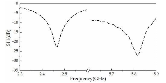
Figure 2.
Simulated S11 of the proposed DRA.
The electric field distributions shown in Figure 3 verify that the proposed DRA resonates at its TEM111 mode at 2.45 GHz, and at 5.8 GHz it resonates at its TEM211 mode. Figure 4 shows the simulated radiation patterns of the proposed DRA at the operating frequency bands. At 2.45 GHz, the cross-polarization of the x-z plane is less than −40 dB, and that of the y-z plane is less than −30 dB. At 5.8 GHz, the cross-polarization of the E plane is also less than −40 dB, and that of the H plane is less than −25 dB. A broad beamwidth can be observed. For 2.45 GHz, the half-power beamwidth (HPBW) is about 120° (E plane) and 90° (H plane). For 5.8 GHz, the HPBW is about 60° (E plane) and 40° (H plane), which can achieve a better performance of energy harvesting.
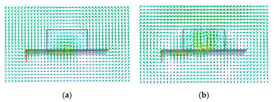
Figure 3.
Electric field distributions on the x-z plane: (a) 2.45 GHz; (b) 5.8 GHz.
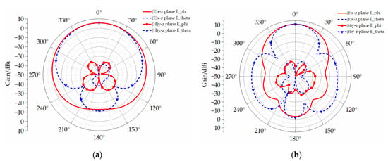
Figure 4.
Simulated radiation patterns of the proposed DRA: (a) 2.45 GHz; (b) 5.8 GHz.
2.2. Antenna Array Design and Measurement
We construct a 4-element antenna array to improve the gain and thereby increase the conversion efficiency using the proposed antenna. The configuration of the antenna array is shown in Figure 5. It consists of two series subarrays. In order to ensure the equal amplitude and phase of the two elements of the subarray, the meandered feed lines and terminal lines are optimized. A Wilkinson power divider is used to feed the array [20].
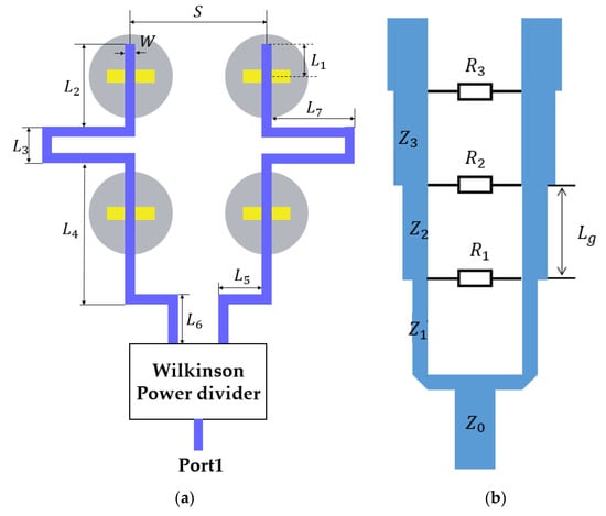
Figure 5.
Configuration of the proposed DRA array: (a) Configuration of the feeder line; (b) Configuration of the wilkinson power divider: L1 = 6 mm; L2 = 25 mm; L3 = 8 mm; L4 = 40 mm; L5 = 20 mm; L6 = 10 mm; L7 = 23 mm; Lg = 18 mm; S = 40 mm; W = 2 mm; Z0 = 50 Ω; Z1 = 86.98 Ω; Z2 = 70.71 Ω; Z3 = 57.49 Ω; R1 = 100 Ω; R2 = 197 Ω; R3 = 373 Ω.
To verify the performance of the DRA array, a prototype is fabricated and measured, as shown in Figure 6. The simulated and measured S11 of the antenna array is shown in Figure 7. The simulated impedance bandwidth with in the lower band is 2.42–2.51 GHz and the measured result is 2.4–2.52 GHz. For the upper band, the simulated bandwidth is 5.74–5.84 GHz, and the measured impedance bandwidth is 5.29–5.91 GHz. It can be observed that a good impedance matching is obtained. The difference between simulated and measured results at upper pass band might be due to the larger machining dimensions and the uneven distribution of dielectric substrate materials.
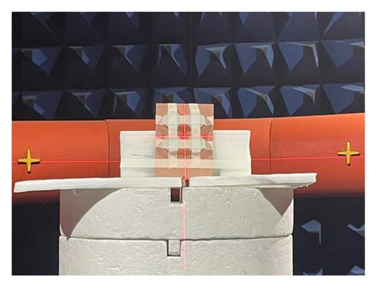
Figure 6.
Test environment of the prototype DRA array.
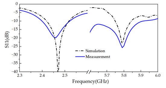
Figure 7.
Simulated and measured S11 of the proposed DRA array.
Figure 8 presents the radiation patterns of the proposed DRA array at lower and upper frequencies. It can be seen that the measured x-z plane radiation patterns at 2.45 GHz and 5.8 GHz are in good agreement with the simulated ones. However, the measured y-z plane radiation patterns (especially the value of E_theta) are somehow different from the simulation. The dielectric block needs to be fixed by the reinforcing tape during the radiation pattern measurement (not considered in the simulation), which leads to a slight difference in the radiation pattern.
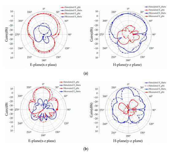
Figure 8.
Simulated and measured radiation patterns of the proposed DRA array: (a) 2.45 GHz; (b) 5.8 GHz.
Figure 9 depicts the simulated and measured gain of the DRA array. The measured and simulated results show good agreement. The simulated and measured gains of the antenna array are 6.2 dBi and 5.5 dBi at 2.45 GHz, respectively. The simulated and measured gains at 5.8 GHz are 14.2 dBi and 12.9 dBi, respectively. Differences are probably owing to two main factors: (1) The insertion loss of the fabricated feeding network is larger than the simulation; (2) The insertion loss of the SMA connector utilized to test the prototype is not included in the simulations.
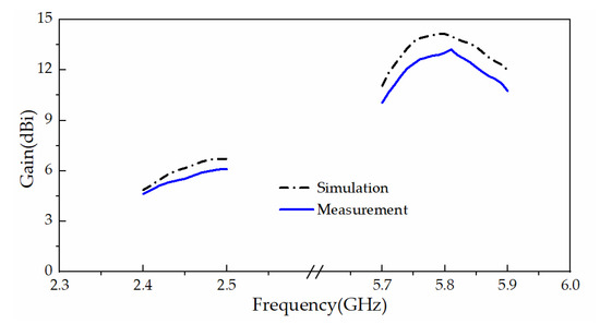
Figure 9.
Simulated and measured gain of the proposed DRA array.
3. Rectifier Design
The rectifying circuit is an important part of the rectenna since it directly determines the performance of the rectenna. A good rectifier must have good power processing capacity. Generally, a rectifying circuit is composed of an impedance matching network, rectifying element (Schottky diode), and a DC-pass filter for smoothing waveform and the load.
The full-wave voltage doubler rectifier is chosen mainly because it is simple and has a higher conversion efficiency than the traditional half-wave rectifier circuit in the application of 10 mW. Its efficiency compared with the traditional single series rectifier circuit is shown in Figure 10. The selection of diodes has a crucial impact on the performance of the rectifier since they bring the main loss. High series resistance (RS) and zero bias junction capacitance (Cj0) of diodes will reduce conversion efficiency [1], while the reverse breakdown voltage (Vbr) of diodes will limit the maximum rectified power. Table 1 compares the important parameters of several commercial rectifying diodes. Finally, the HSMS2860 Schottky diode is selected, which has high voltage sensitivity at low input power.
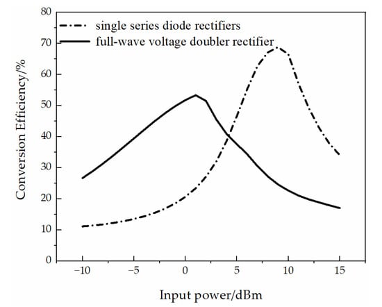
Figure 10.
Conversion efficiency comparison between single series diode rectifier and full-wave voltage doubler rectifier.

Table 1.
Parameters of several commercial Schottky diodes.
The rectifier at the operating frequency is designed and optimized. For 10 mW applications, harmonic balance (HB) in ADS software is used for simulation. The final design is shown in Figure 11.

Figure 11.
Configuration of the proposed rectifier circuit: l1 = 3.5 mm; l2 = 8.7 mm; l3 = 6.3 mm; l4 = 6.6 mm; l5 = 5.1 mm; l6 = 12.9 mm; l7 = 5.1 mm; l8 = 1.5 mm; w1 = 1 mm; w2 = 1.8 mm; w3 = 0.4 mm; w4 = 1.2 mm; w5 = 0.8 mm.
The proposed rectifier is built on a Rogers 5880 dielectric substrate (h = 0.254, ε = 2.2, δ = 0.0009). The capacitance value of the two capacitors is 100 nF. It is worth noting that for the rectifier circuit design, the impedance matching network can directly affect the performance of the rectifier circuit. In order to achieve good impedance matching in dual-band, a new type of impedance regulation stub (IRS) is proposed, as shown in Figure 12. The proposed IRS directly converts the impedance of the full-wave voltage doubler rectifier into a value that easily achieves dual-band impedance matching. The detailed impact of a matching network and IRS on RF–DC conversion efficiency has been simulated in Figure 13. It shows the following: Efficiency (00): the conversion efficiency of the rectifier when neither the matching network nor the IRS exist; Efficiency (10): conversion efficiency of the rectifier when only the matching network exists; Efficiency (01): conversion efficiency of the rectifier when only the IRS exists; Efficiency (11): conversion efficiency of the rectifier when both the matching network and the IRS exist.
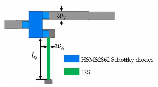
Figure 12.
Configuration of the proposed IRS: l9 = 4.4 mm; w6 = 0.4 mm; w7 = 0.9 mm.
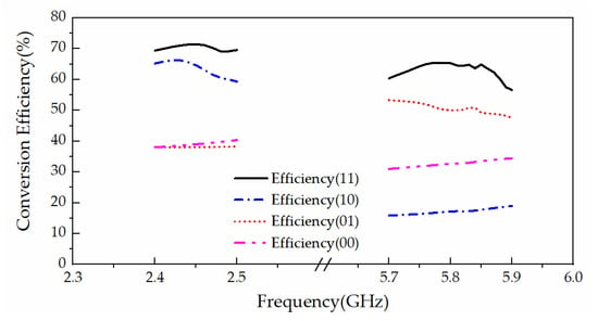
Figure 13.
The detailed impact in the four cases on conversion efficiency.
The proposed rectifier is fabricated and it is shown in Figure 14. The conversion efficiency measurement setup is displayed in Figure 15. The power source is a 2–6 GHz signal generator; a multimeter is utilized to measure the DC voltage across the load, and the efficiency is calculated as:
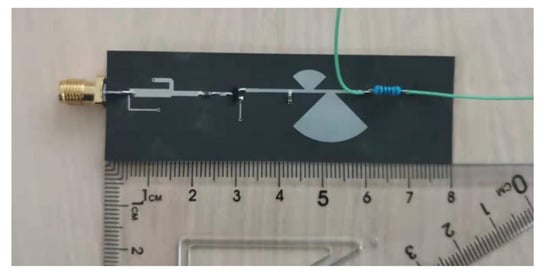
Figure 14.
Fabrication of the proposed rectifier.
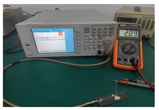
Figure 15.
Conversion efficiency measurement setups.
Where VDC is the DC voltage across the load, RL is the load resistance value, and Pr is the RF input power. The load resistance is 2 KΩ since it is suitable for many small wireless devices. The input power level is selected as 10 dBm due to the good performance at this input level for signals of two frequencies in the simulation. It can be seen that the proposed rectifier circuit covers the required frequency bands in Figure 16. At 2.45 GHz, the simulated rectifier efficiency is 72% and the measured result is 66%. At 5.8 GHz, the simulated rectifier efficiency is 65% and the measured result is 62%. The measured efficiency is lower at both low frequency and upper frequency bands, which might be caused by the difference in diode parameters between simulation and fabrication.
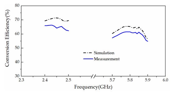
Figure 16.
Simulated and measured conversion efficiency of the proposed dual-band rectifier.
When the load resistance is 2 KΩ, the measured conversion efficiency variation with the input power level at 2.45 GHz and 5.8 GHz frequency is shown in Figure 17. The efficiency can be maintained above 50% when the input power level is 0–15 dBm (2.45 GHz) and 5–13 dBm (5.8 GHz). Figure 18 shows the measured conversion efficiency varying with load resistance at 2.45 GHz and 5.8 GHz. When the load resistance is 1–8 KΩ (2.45 GHz) and 0.8–2.2 KΩ (5.8 GHz), the efficiency can be maintained above 50%. The range for 5.8 GHz is very small, which is caused by larger diode loss at higher frequency.
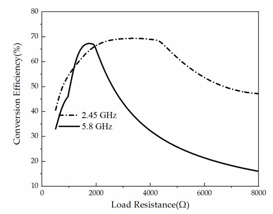
Figure 17.
Measured conversion efficiency (Input power level is 10 dBm).
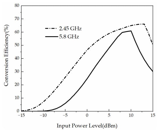
Figure 18.
Measured conversion efficiency (load resistance is 2 KΩ).
4. Rectenna Performance
4.1. Rectenna Measurement
The receiving antenna and rectifying circuit make up the rectifying antenna. Pr is the input power received by the antenna; Pr can be calculated by the Friis transmission equation:
In this paper, λ is the wavelength of the operating frequency, r is the distance between the transmitting antenna and the proposed DRA array, Pt is the transmission power. Gt is the gain of the transmitting antenna, and Gr is the gain of the proposed DRA array. Figure 19 shows the conversion efficiency measurement setups of the proposed rectenna. The microwave power output from a signal generator is amplified by an amplifier with a gain of 42 dB. A broadband horn is used to transmit energy signals. The receiving antenna is at the distance r from the horn. The measurement procedure is as follows:
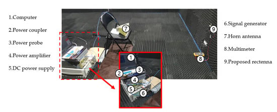
Figure 19.
The conversion efficiency measurement setups of the proposed rectenna.
- Measuring the gain of the standard broadband horn antenna: a vector network analyzer is used to measure the insertion loss of the coaxial line which is used to connect the DRA array and the rectifier circuit in the experiment;
- Add a 3 dB coupler behind the signal generator; one port is connected to the power probe, and the other port is connected to the broadband horn. On the premise of meeting the dual frequency far-field conditions, the distance between the broadband horn and the proposed DRA array is fixed as r; measure the input power at the broadband horn;
- The receiving power at 2.45 GHz and 5.8 GHz is calculated according to the Friis transmission equation;
- The voltage across the load resistance is measured with a multimeter, and the efficiency of the rectenna is calculated.
The measured results are given in Table 2. The conversion efficiency of the proposed rectenna reaches 47.7% at 2.45 GHz and 40.3% at 5.8 GHz. The results show that the proposed rectenna can efficiently harvest RF energy. Compared with the performance of the rectifier, the conversion efficiency decreases. This could be caused by two things. On one hand, due to the error of the power probe, there may be measurement error in the transmission power. On the other hand, the DRA array and rectifier circuit are integrated on different dielectric substrates; the RF adapter connecting the proposed DRA array and the rectifier circuit have unavailable parasitic behavior.

Table 2.
Measured results of the rectenna performance.
To highlight the advantages of the proposed design, a few up-to-date reported rectennas have been compared with the proposed rectenna in Table 3. The gain of our design at 5.8 GHz is superior. Thanks to the novel IRS-loaded impedance matching network, the RF-DC conversion efficiency of our rectifier is significantly higher than other dual-band designs. Furthermore, the DRA matches well with the rectifier, and we achieve a superior conversion efficiency of the rectenna. The rectenna has a good performance in reported letters, so it is a good solution for RF energy harvesting in practice.

Table 3.
Comparison of the proposed rectenna and similar reported designs.
4.2. DC-DC Boost Measurement
In application, the low available electromagnetic power density limits the use of rectenna in WEH applications. In addition, the ultra-low power makes it impossible to directly supply power to sensors. Therefore, a DC-DC boost converter is proposed to handle the smaller voltage and store the DC energy in the storage element.
The proposed rectenna is used as the source of the BQ25504, which can be activated when the input DC power reaches 330 mV. The DC-DC boost converter can reach an output voltage of 3.2 V.
As shown in Figure 20a, we connect the BQ25504-674 EVM to a supercapacitor (BZ015A503ZSB). Then the voltage across the supercapacitor is measured in the oscilloscope shown in Figure 20b. It can be seen that the voltage value across the supercapacitor increases from 1.4 V to 3.2 V within 50 s. The stored power can be calculated as:
where Pstore is the stored power, C is the capacitance of the supercapacitor, Vafter is the voltage after charging and Vbefore is the voltage before charging. The capacitance of the selected supercapacitor is 50 mF, so the supercapacitor stores 0.207 J within 50 s. This indicates that the proposed rectifier has the potential to provide energy for low-power devices.
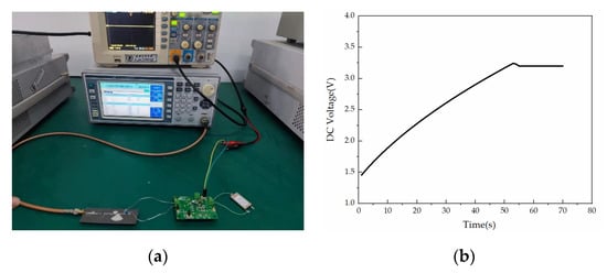
Figure 20.
The conversion efficiency measurement. (a) Measurement setups; (b) DC Voltage across the supercapacitor.
5. Conclusions
This paper introduces the design of a rectenna at 2.45 GHz and 5.8 GHz for energy harvesting. A DRA is proposed to design the receiving antenna. To further improve the gain of the receiving antenna, a compact feed network is designed to excite a 4-element DRA array. The measured gains of the DRA array are 5.5 dBi at 2.45 GHz and 12.9 dBi at 5.8 GHz. For the rectifier, a novel IRS is proposed to significantly improve the efficiency of the rectifier circuit. The rectenna is processed and tested. The measurement results show the maximum conversion efficiency can reach 66% at 2.45 GHz and 62% at 5.8 GHz when the input power level is 10 dBm. Moreover, a DC-to-DC boost converter can be used. With its superior performance, the rectenna is suitable for various ultra-low applications.
Author Contributions
Conceptualization, J.L. and Z.L. (Zan Liu); methodology, C.J. and Z.L. (Zan Liu); investigation, Z.L. (Ziyue Li); resources, Z.L. (Zan Liu); writing—original draft preparation, Z.L. (Ziyue Li); writing—review and editing, J.L.; visualization, T.W.; supervision, J.L.; project administration, C.J.; funding acquisition, Z.L. (Zan Liu). All authors have read and agreed to the published version of the manuscript.
Funding
This work was supported by the National Key R&D Program of China under Grant 2019YFB2101601.
Institutional Review Board Statement
Not applicable.
Informed Consent Statement
Not applicable.
Data Availability Statement
All data are available from the author.
Conflicts of Interest
The authors declare no conflict of interest.
References
- Song, C.; Huang, Y.; Carter, P.; Zhou, J.; Yuan, S.; Xu, Q.; Kod, M. A novel six-band dual CP rectenna using improved impedance matching technique for ambient RF energy harvesting. IEEE Trans. Antennas Propag. 2016, 64, 3160–3171. [Google Scholar] [CrossRef]
- Zhang, H.; Gao, S.-P.; Wu, W.; Guo, Y.-X. Uneven-to-even power distribution for maintaining high efficiency of dual-linearly polarized rectenna. IEEE Microw. Wirel. Compon. Lett. 2018, 28, 1119–1121. [Google Scholar] [CrossRef]
- Georgiadis, A.; Vera Andia, G.; Collado, A. rectenna design and optimization using reciprocity theory and harmonic balance analysis for electromagnetic (EM) energy harvesting. IEEE Antennas Wirel. Propag. Lett. 2010, 9, 444–446. [Google Scholar] [CrossRef]
- Awais, Q.; Jin, Y.; Chattha, H.T.; Jamil, M.; Qiang, H.; Khawaja, B.A. A compact rectenna system with high conversion efficiency for wireless energy harvesting. IEEE Access 2018, 6, 35857–35866. [Google Scholar] [CrossRef]
- Sakamoto, T.; Ushijima, Y.; Nishiyama, E.; Aikawa, M.; Toyoda, I. 5.8-GHz series/parallel connected rectenna array using expandable differential rectenna units. IEEE Trans. Antennas Propag. 2013, 61, 4872–4875. [Google Scholar] [CrossRef]
- Ren, Y.; Chang, K. 5.8-GHz circularly polarized dual-diode rectenna and rectenna array for microwave power transmission. IEEE Trans. Microw. Theory Tech. 2006, 54, 1495–1502. [Google Scholar]
- Heikkinen, J.; Kivikoski, M. Low-profile circularly polarized rectifying antenna for wireless power transmission at 5.8 GHz. IEEE Microw. Wirel. Compon. Lett. 2004, 14, 162–164. [Google Scholar] [CrossRef]
- Heikkinen, J.; Kivikoski, M. A novel dual-frequency circularly polarized rectenna. IEEE Antennas Wirel. Propag. Lett. 2003, 2, 330–333. [Google Scholar] [CrossRef]
- Roy, S.; Tiang, R.J.-J.; Roslee, M.B.; Ahmed, M.T.; Mahmud, M.A.P. Quad-band multiport rectenna for RF energy harvesting in ambient environment. IEEE Access 2021, 9, 77464–77481. [Google Scholar] [CrossRef]
- Liu, Z.; Zhong, Z.; Guo, Y.-X. Enhanced dual-band ambient RF energy harvesting with ultra-wide power range. IEEE Microw. Wirel. Compon. Lett. 2015, 25, 630–632. [Google Scholar] [CrossRef]
- Song, C.; Huang, Y.; Zhou, J.; Zhang, J.; Yuan, S.; Carter, P. A high-efficiency broadband rectenna for ambient wireless energy harvesting. IEEE Trans. Antennas Propag. 2015, 63, 3486–3495. [Google Scholar] [CrossRef]
- Du, Z.; Bo, S.F.; Cao, Y.F.; Ou, J.; Zhang, X.Y. Broadband circularly polarized rectenna with wide dynamic-power-range for efficient wireless power transfer. IEEE Access 2020, 8, 80561–80571. [Google Scholar] [CrossRef]
- Song, C.; Huang, Y.; Carter, P.; Zhou, J.; Joseph, S.D.; Li, G. Novel compact and broadband frequency-selectable rectennas for a wide input-power and load impedance range. IEEE Trans. Antennas Propag. 2018, 66, 3306–3316. [Google Scholar] [CrossRef]
- Matsunaga, T.; Nishiyama, E.; Toyoda, I. 5.8-GHz stacked differential rectenna suitable for large-scale rectenna arrays with DC connection. IEEE Trans. Antennas Propag. 2015, 63, 5944–5949. [Google Scholar] [CrossRef]
- Sun, H.; Geyi, W. A new rectenna using beamwidth-enhanced antenna array for RF power harvesting applications. IEEE Antennas Wirel. Propag. Lett. 2017, 16, 1451–1454. [Google Scholar] [CrossRef]
- Song, C.; Huang, Y.; Zhou, J.; Carter, P.; Yuan, S.; Xu, Q.; Fei, Z. Matching network elimination in broadband rectennas for high-efficiency wireless power transfer and energy harvesting. IEEE Trans. Ind. Electron. 2017, 64, 3950–3961. [Google Scholar] [CrossRef]
- Noghabaei, S.M.; Radin, R.L.; Savaria, Y.; Sawan, M. A high-sensitivity wide input-power-range ultra-low-power RF energy harvester for IoT applications. IEEE Trans. Circuits Syst. I Regul. Pap. 2022, 69, 440–451. [Google Scholar] [CrossRef]
- Lin, Q.W.; Zhang, X.Y. Differential rectifier using resistance compression network for improving efficiency over extended input power range. IEEE Trans. Microw. Theory Tech. 2016, 64, 2943–2954. [Google Scholar] [CrossRef]
- Au, N.D.; Le-Huu, H.; Seo, C. A wide dynamic-range rectifier at 433 MHz for multiple-antenna impedances. IEEE Microw. Wirel. Compon. Lett. 2021, 31, 196–199. [Google Scholar] [CrossRef]
- Chongcheawchamnan, M.; Patisang, S.; Krairiksh, M.; Robertson, I.D. Tri-band wilkinson power divider using a three-section transmission-line transformer. IEEE Microw. Wirel. Compon. Lett. 2006, 16, 452–454. [Google Scholar] [CrossRef]
- Saito, K.; Nishiyama, E.; Toyoda, I. A 2.45- and 5.8-GHz dual-band stacked differential rectenna with high conversion efficiency in low power density environment. IEEE Open J. Antennas Propag. 2022, 3, 627–636. [Google Scholar] [CrossRef]
- Kumar, M.; Kumar, S.; Sharma, A. Dual-purpose planar radial-array of rectenna sensors for orientation estimation and rf-energy harvesting at IoT nodes. IEEE Microw. Wirel. Compon. Lett. 2022, 32, 245–248. [Google Scholar] [CrossRef]
- Lu, P.; Huang, K.; Song, C.; Ding, Y.; Goussetis, G. Optimal power splitting of wireless information and power transmission using a novel dual-channel rectenna. IEEE Trans. Antennas Propag. 2022, 70, 1846–1856. [Google Scholar] [CrossRef]
- Guo, L.; Li, X.; Sun, W.; Yang, W.; Zhao, Y.; Wu, K. Designing and modeling of a dual-band rectenna with compact dielectric resonator antenna. IEEE Antennas Wirel. Propag. Lett. 2022, 21, 1046–1050. [Google Scholar] [CrossRef]
- Muhammad, S.; Tiang, J.J.; Wong, S.K.; Smida, A.; Ghayoula, R.; Iqbal, A. A dual-band ambient energy harvesting rectenna design for wireless power communications. IEEE Access 2021, 9, 99944–99953. [Google Scholar] [CrossRef]
- Wagih, M.; Hilton, G.S.; Weddell, A.S.; Beeby, S. Dual-polarized wearable antenna/rectenna for full-duplex and MIMO simultaneous wireless information and power transfer (SWIPT). IEEE Open J. Antennas Propag. 2021, 2, 844–857. [Google Scholar] [CrossRef]
- Lu, P.; Song, C.; Huang, K.M. Ultra-wideband rectenna using complementary resonant structure for microwave power transmission and energy harvesting. IEEE Trans. Microw. Theory Tech. 2021, 69, 3452–3462. [Google Scholar] [CrossRef]
- Bhatt, K.; Kumar, S.; Kumar, P.; Tripathi, C.C. Highly efficient 2.4 and 5.8 GHz dual-band rectenna for energy harvesting applications. IEEE Antennas Wirel. Propag. Lett. 2019, 18, 2637–2641. [Google Scholar] [CrossRef]
- Shi, Y.; Fan, Y.; Li, Y.; Yang, L.; Wang, M. An efficient broadband slotted rectenna for wireless power transfer at LTE band. IEEE Trans. Antennas Propag. 2019, 67, 814–822. [Google Scholar] [CrossRef]
Publisher’s Note: MDPI stays neutral with regard to jurisdictional claims in published maps and institutional affiliations. |
© 2022 by the authors. Licensee MDPI, Basel, Switzerland. This article is an open access article distributed under the terms and conditions of the Creative Commons Attribution (CC BY) license (https://creativecommons.org/licenses/by/4.0/).