Article

Analysis of Damage of Typical Composite/Metal Connecting Structure in Aircraft under the Influences of High-Velocity Fragments

1
Aviation Engineering School, Air Force Engineering University, Xi’an 710038, China
2
School of Aeronautics, Northwestern Polytechnical University, Xi’an 710072, China
*
Author to whom correspondence should be addressed.
Appl. Sci. 2022, 12(18), 9268; https://doi.org/10.3390/app12189268
Submission received: 24 August 2022 / Revised: 11 September 2022 / Accepted: 12 September 2022 / Published: 15 September 2022
(This article belongs to the Special Issue Blast and Impact Engineering on Structures and Materials)

Abstract

:
A two-stage light gas gun was used to conduct a high-velocity impact test on the aircraft’s typical composite/metal connecting structure (CFRP/AL). The battle damage simulations used for the CFRP/AL connecting structure were carried out under different intersection conditions. Then, the damage morphology and mechanism of high-velocity prefabricated spherical fragments on typical structures, the dynamic process of hyper-velocity impact, and the formation of debris clouds on the secondary damage morphology of different component structures were investigated. Next, based on the X-ray computerized tomography (CT), the typical mode of different damage areas and evolution trends of CFRP under high-velocity impacts were explored. Finally, a simulation model was established for battle damages of typical structures by combining FEM methods, and structural components’ energy dissipation capabilities for fragments under different velocities were analyzed. The study results provide a reference and model support for the rapid repair of battle-damaged aircraft and aircraft survivability design.

1. Introduction

The problem of damage repair of aviation weapon equipment on the battlefield has a long history. According to statistics, the number of battle-damaged aircraft is much greater than the number of battle-destroyed aircraft. Hence, rapid repair of battle-damaged aircraft can have a significant impact on the war situation by increasing operational intensity and ensuring sustained combat capability. Indeed, rapid repair of battle-damaged aircraft has attracted great attention as it is the most effective way to restore aircraft combat effectiveness [1].
The battle damage mode of aircraft is to study all possible conditions and combinations of threat sources causing battle damage. The battle damage simulation based on rapid repair is different from weapon effectiveness analysis, and the combat effectiveness and survivability analysis of aircraft. The purpose is to provide guidance on rapid repair techniques and to provide an aid for the analysis of rapid repair resource requirements, usually focusing on the analysis and research of battle damage of aircraft structures. The combat aircraft is the main target of all types of air defense weapons.
Currently, carbon fiber composites have been widely applied in advanced fighters, especially in wing panels, vertical fins, fuselage skins, and rudders [2]. Carbon fiber laminates are the most important aerospace composite structure. The damage of a composite structure under the impact of combat fragments is different from that of a metallic structure, and its damage mechanism is more complex than that of metallic material. On one hand, the reinforced fiber limits the expansion of damage under the composite structure’s own load, and on the other hand, the damage modes (such as the delamination of composite laminate structures) are not found in aerospace metal structures. The impact of the combat fragments on the composite laminate is a complex process of impact load evolution with time, structural deformation and damage extension. The impact damage of composite laminate is closely related to the laminate material’s properties, lamination method, processing technology and the fragment’s velocity, shape and quality. The damage mode and damage range of the laminate are different in different impact conditions. The possible damage mechanisms include fiber shear fracture, fiber tensile failure, matrix cracking, fiber matrix interface delamination and degumming. The damage mechanism and damage mode of a composite structure in a series of velocity ranges were investigated by numerical simulation and experiments. Thomas et al. conducted a hyper-speed impact test on CFRP/Al honeycomb composites and obtained the dynamic response of the structure with different thickness combinations [3]. Miao et al. conducted a hyper-speed impact test and impact damage test analysis to solve the protection effect problem of a spatial debris soft protection structure composed of a soft protection screen made of multilayer soft composites [4]. Phadnis et al. conducted a CFRP-Al/HC sandwich panel hyper-speed impact behavior analysis based on the finite element method. Coles et al. conducted ballistic tests on braided T300 carbon fiber/epoxy composite flat-plate specimens and 3D X-ray computer tomography (CT) was used to image and visualize the resultant damage inside the samples.
Modern aircraft are mostly multilayered thin-walled structures. Aircraft skin will often encounter penetrating damage under the action of high-velocity fragments, which has considerable penetration capabilities after penetrating the outer skin, and the secondary penetration of fragments will cause damage to the internal structure. The damage mode is closely related to the fragment’s incident direction, incident velocity, and strike position [5].
The damage mode of aircraft composite/metal connecting structures under high-velocity impact has been little studied. Aiming at the carbon-fiber-reinforced laminate/Al alloy connection frame structure of a certain type of aircraft wing, the damage mode under the action of high-velocity spherical fragments (1600–2400 m/s) was investigated based on the numerical simulation model of simulated impact tests and the display dynamics of the two-stage light gas gun system.

2. Experimental

The multistage light gas gun is commonly used to achieve the high-velocity loading of small-sized projectiles and is often used in tests related to spacecraft collisions with space debris, and its technical indicators can achieve the requirements for fragment intrusion into aircraft structures [6]. The characteristic structure equal ratio test piece, fragment and the corresponding Sabot were prepared. Based on the two-stage light gas gun system, the simulated penetration of prefabricated spherical fragments into aircraft-typical vulnerable structures under different working conditions was realized.

2.1. Instrument

The two-stage light gas gun was used as the launcher, and a 10# steel ball (diameter = 8 mm) was used to simulate the prefabricated fragment of the missile, as shown in Figure 1. The target structure is fixed in the chamber by the fixture, adjusted to the corresponding strike position, and the intended test strike position is marked by the laser pointer, as shown in Figure 2 and Figure 3.
The target chamber is connected to the end of the secondary stage barrel, which is equipped with an optical beam blocking (OBB) sensor system to measure the exit velocity of the launched projectile. Three laser beams of similar intensity are placed in the projectile’s path and directed to the photoelectric tube connected to the timer. The skimming of the projectile will block the laser beam, and the resulting pulse signal will be recorded on the timer by the photoelectric tube. The projectile velocity is obtained by comparing the time interval of the timer and the distance between the laser beams. The target chamber is equipped with bullet-proof glass observation windows on both sides and a high-velocity camera (Phantom V2512) for capturing the impact process, and a flash for the high-velocity camera to fill in the light. The high-velocity camera uses a 50 mm fixed-focus lens, and records at a pixel of 386 × 216 with a frame rate of 160 kfps, as shown in Figure 4.
The YXLON FF85 CT scanning system is equipped with two sets of radiation tubes and a large-sized flat detector for the detection of all types of damage on fiber-enhanced composites. The inspection sample is scanned layer by layer by emitting X-ray, and in combination with the analysis software, the composite can be inspected and global damage 3D modeling and rendering can be achieved. In this study, it is mainly used to implement the internal damage analysis and overall damage assessment of the composite, as shown in Figure 5.

2.2. Test Piece

The composite/Al alloy joint spacer frame structure test piece, as shown in Figure 6, consists of an Al alloy top skin, rib 1, rib 2, and with a composite bottom skin and stringer. The top skin is connected to rib 1 and rib 2 by 8 mm rivets, and the composite bottom skin is connected to rib 1 and rib 2 by high-locking bolts. The Al alloy is AL7075-T6 produced by Chalco Group, using the GB/T29503-2013 standard, and the composite material is T300/QY8911 epoxy resin-based carbon fiber unidirectional laminate. It contains bottom skin (45/−45/0/−45/0/45/0/45/0/45/−45/0/90/45/90/45/90/0/−45/45/0/−45/45/0/45/0/−45/0/−45/0/−45/45) and stringer (45/−45/0/−45/45/0/−45/0/−45/0/45/0/90/90/0/45/0/−45/0/45/−45/0/−45/45). The laminate was laid orthogonally and symmetrically with plain woven prepreg, as shown in Figure 7.

3. Damage Analysis

3.1. Analysis of Impact Process

A high-speed camera (frame rate 160 kfps) is used to capture the dynamic process of the intersection of the spherical fragments with the structure, as shown in Figure 8.
Situation 1: The fragment is incident from the bottom skin composite side at an incidence angle of 45°, and the measured fragment exit velocity is 2327 m/s. The moment the fragment intersects with the structure, a strong photo-thermal phenomenon is generated at the impact location, resulting in local overexposure of the high-velocity camera. Subsequently, the fragment penetrates the structure and forms a debris cloud on the outside of the structure, accompanied by a splash of massive fiber. As the invasion progresses, the composite laminate forms a bulge. The rapid rupture of the bulge forms a debris cloud, which is mainly composed of broken small-diameter carbon fiber particles. The outer debris cloud at the incident end expands radially along the vertical direction of fragment incidence, and its main components are bulk fiber debris and fragment metal particles, while the inner debris cloud at the incident end expands radially along the direction of fragment incidence, and its main components are small-diameter carbon fiber debris groups.
Situation 2: The dynamic intersection process of the fragment and structure in Situation 2 is similar to that shown in Situation 1. Due to the change in the direction of incidence, there is a difference in the expansion pattern of the debris cloud between the two. In Situation 2, the difference between the inner and outer debris cloud’s highlight phenomena is more obvious, again due to the difference in their main components. The small-diameter carbon fiber debris group has a black main layer with dense spatial distribution and strong light absorption, and the photo-thermal phenomena captured by the high-velocity camera in the inner part of the incident section are weak.
Situation 3: The fragment intruded from the top skin Al alloy side, and the photo-thermal phenomena were stronger both inside and outside. In Situation 1/2, when the projectile intrudes from the composite side, unlike the metal side, the carbon fiber breaks up to generate a large amount of dusty debris cloud, and the debris cloud is dominated by the carbon fiber debris, which will cover the entire high-velocity camera capture area, and the radial velocity is larger than the incident velocity during the expansion of the debris cloud. It is because the composite is made out of anisotropic material that when the impact direction is perpendicular to the fiber layup, the fiber is susceptible to shear fracture, and its normal strength is much lower than that of the metal material, resulting in a difference in the morphology of the bulge formed in the impact process, and therefore, the morphology of debris cloud diffusion formed in the final bulge rupture is also different. The shock photo-thermal phenomena in Situation 1/2 are not as obvious as in Situation 3, and the main component of the firelight is the high-temperature metal fragments. Due to the violent friction between steel spherical fragments and Al alloys during the impact penetration process, the temperature is extremely high, resulting in the appearance of small metallic debris and the release of part of the heat accumulated by friction in the pattern of luminescence.

3.2. Composite Damage Analysis

In Situation 1/2, the damage morphology of the structural composite top skin and the stringer intrusion by the high-velocity spherical fragments are shown in Figure 9 and Figure 10, respectively. The damage broken hole is mainly ellipsoidal under the 45° oblique impact of the fragment in Situation 1. In Situation 2, under the positive impact of fragment 0°, the damage broken hole is mainly in the pattern of regular spherical rupture. In Situation 1/2, there is fiber spalling on the outer surface of the incidence. The stringer part is thin and shows a band-like broken hole under the shearing effect in both Situation 1/2.
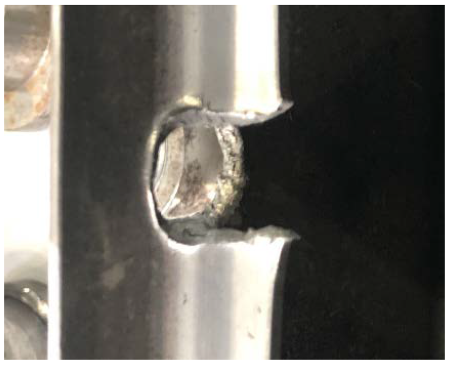
In Situation 3, the fragment is incident from the Al alloy metal side. According to Figure 11, the fragment formed a debris cloud consisting of a large number of metal particles when it penetrated the top skin. The debris cloud still has a high kinetic energy, and the secondary damage formed at the bottom skin, which is mainly in the pattern of small-diameter broken holes and surface spalling, is widely distributed.
The test piece composite part was scanned by CT, and the damage morphology feature images of the composite test piece were obtained for each directional interface, layer by layer, and then the 3D view of the damage of the test piece composite part under each working condition was obtained by image rendering, as shown in Figure 12.
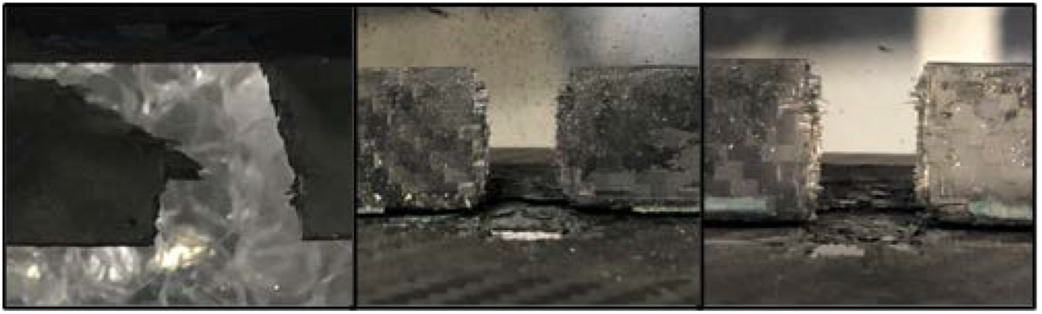
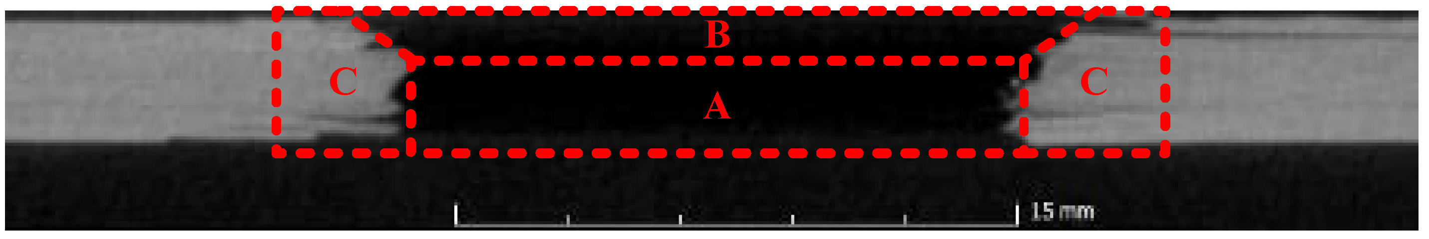
The section of composite laminate damage area under high-velocity impact of spherical fragments is mainly in the pattern of a combination of cylindrical and circular truncated cones, as shown in Figure 13. In his study on the impact damage of aramid laminate, Reddy pointed out that the damage aperture of thick plates decreases slightly along the thickness direction and then increases rapidly, while the aperture of thin plates expands in the shape of a circular truncated cone, and Cantwell et al. used the combined area of a cylindrical and circular truncated cone [7,8,9]. In the early stage of projectile penetration, the front side of the laminate would generate a shear-plugging hole similar to the shape of the projectile contact area, where the matrix material is crushed and loses its support to the fiber, and shear failure occurs between the fiber and the surrounding fiber due to the presence of a large velocity gradient, which is called the shear failure zone (A). With the continuation of the penetration process, the projectile velocity decreases, the target plate bends, and with the continuous expansion of the bending deformation, fiber tensile failure occurs first in the outermost layer of the back side of the impact, and the tensile failure expands from the outer layer to the back side with a certain crack inclination angle and produces delamination, forming a fiber tensile failure zone behind the shear failure zone (B). Meanwhile, there is a small delamination damage zone around the shear failure zone/fiber tensile failure zone (C). In this test, the delamination zone of laminate caused by the high-velocity impact of spherical fragments is limited, and the fiber in the zone is mainly recoverable deformation without significant fiber damage.
The projection of the laminate damage area in the direction of fragment incidence shows different morphological features in different damage areas, as shown in Figure 14. Herein, the position of the blue line is the position of the broken hole section in the vertical plane. On the upper surface of the shear failure zone, the main body of the broken hole section is circular. The laminate-free surface is strongly impacted by spherical fragments, and there are more striated fiber-stripping areas around the circular rupture holes. As the penetration progresses, the breach section inside the shear failure zone is mainly regular circular, and the area of the spalling zone decreases. At the shear failure zone/fiber tensile failure zone intersection, the breach section has common features of both. The shape of the breach section is transformed from a shear failure-oriented circle to a fiber tensile failure-oriented square. As the penetration progresses, the breach section in the fiber tensile failure zone appears as a regular square.
High-speed fragmentation spherical fragment intrusion CFRP, in the process of damage formation, can be divided into four stages as shown in Figure 14. In shear and tensile damage, the compression wave generated by the spherical fragment acting on the target plate propagates faster than the projectile movement, and the strong tensile wave formed by the reflection of the compression wave on the back of the target plate meets the projectile, and the meeting point is the interface between shear damage and tensile damage. When the tensile stress is greater than the bonding strength of the fibers and the substrate or the tensile strength of matrix material, tensile stress is induced at the defective area and is accompanied by partial delamination. Eventually the fibers fracture and splash under the impact, which is in line with the phenomenon captured by the high-speed camera.
As shown in Figure 15, from left to right are the upper surface, shear failure zone, area boundary, tensile failure zone, and lower surface of the broken hole morphology, respectively. The evolutionary pattern of breach section morphology shows a similar pattern under different velocities. Notably, as the fragment impact velocity decreases, the size of the laminate-free surface spalling area decreases significantly.

3.3. Analysis of Al Alloy Damage

Under the Situation 1 incidence condition, the fragment penetrated the bottom skin and a debris cloud hit the rib of the structure. The fragment’s main body with small-diameter debris intruded to generate an ellipsoidal rupture hole. The thinner part of the rib is torn and fractured by the impact, as shown in Figure 16.
For Situation 2’s incidence conditions, four sets of velocity gradient variables were set in the range of the actual fragment velocity. The debris cloud composed of small-diameter carbon fiber particles formed by the fragment penetrating the bottom skin composite side does not have the energy to generate a distributed secondary image on the top skin side of the Al alloy. The top skin side damage is mainly caused by residual fragment penetration. The spherical fragments are separated into two parts by the erosion of composite laminate and the shearing effect of stringer, forming shear holes in the top skin. From the contact between the fragment and the top skin, the annular shear stress formed by the impact is much larger than the panel’s ultimate strength, the annular shear zone then gradually accumulates and expands to the back of the panel to generate an annular shear surface. The shear punching is completed to generate a bulge, the radial tensile stress at the back of the back panel bulge then rises, with the depth of the intrusion, the tensile stress accumulates and expands, when the accumulation exceeds the ultimate strength of the panel, and the bulge fractures and breaks rapidly, forming a petal-shaped irregular fracture. The greater the initial velocity of the fragment, the greater the reaction force received in the impact process, and the farther apart the two separated parts will be. As the velocity decreases, the two holes are connected and eventually generate a single hole, as shown in Figure 17.
Under Situation 3’s incidence conditions, the top skin Al alloy exhibits a relatively regular spherical shape in the entire damage area under the high-shearing effect of the fragment’s high-velocity impact, and its area is basically the same as the area of the orthogonal projection of the spherical fragments. The reinforced ribs develop a columnar erosion zone under the high-shearing effect of the fragment, and the edges show the typical metal cutting marks under the high-shearing effect and the ablation marks caused by the accumulated heat of impact, as shown in Figure 18.

3.4. Numerical Modeling

In order to compensate for the limitation of the number of experiments, a fragment impact composite/metal connecting structure model based on LS-DYNA was established. In composite modeling, the * PART_COMPOSITE keyword is used to define the basic physical parameters such as the thickness of each layer of the composite carbon fiber laminate component, and the layup direction. In order to better reflect the loss between different layers independently in the modeling, and to take into account the computational scale and efficiency, a modeling scheme of one 2D shell cell layer is used instead of four to five actual layers, i.e., five 2D shell cell layers (i.e., elements in the meshing) are used in the simulation modeling instead of 25 actual layers of composite material for the bottom skin components, and five 2D shell unit layers are used instead of 22 actual layers of composite material for the stringer components.
The * MAT_COMPOSITE_DAMAGE model is a composite constitutive model commonly used on shell units, containing physical quantities such as density, fiber elastic modulus in three directions, Poisson’s ratio, shear modulus and longitudinal tensile strength, and transverse tensile strength, and can be used to define various orthogonal anisotropic materials with brittle fractures, which is applicable to the T300/QY8911 epoxy resin-based carbon fiber unidirectional laminate in this study. The single-layer carbon fiber laminate thickness direction size is much smaller than the other direction size. Hence, it can be analyzed according to the plane stress problem, considering only the in-plane stress state, ignoring the plane normal upward stress. The stress–strain relationship can be expressed as:
[ σ ] = [ S ] [ ε ]
1 [ S ] = [ 1 E 11 ν 12 E 11 ν 31 E 33 ν 12 E 11 1 E 22 ν 23 E 23 ν 31 E 33 ν 23 E 23 1 E 33 0 0 1 2 G 12 0 0 0 1 2 G 23 0 0 0 1 2 G 31 ]
where σ is the stress, ε is the strain, E is the elastic modulus, γ is the Poisson’s ratio, and G is the shear modulus.
The * MAT_COMPOSITE_DAMAGE model uses the Chang–Chang failure criterion and has the following four failure modes:
(1)
If σ a a > 0 , fiber is in the stretched state, when satisfied:
( σ a a X T ) 2 + β ( σ a b S c ) 1 0
Herein, E a = E b = ν b a = ν a b = G a b = 0 and the fiber undergoes stretching failure;
(2)
If σ a a < 0 , the fiber is in compression, when the following conditions are met:
( σ a a X C ) 2 1 0
Herein, E a = ν b a = ν a b = 0 and the fiber fails in compression;
(3)
If σ b b > 0 , the fiber matrix is in a stretched state, when the following conditions are met:
( σ a a Y T ) 2 + ( σ a b S c ) 1 0
Herein, E a = ν b a = G a b = 0 and the fiber matrix undergoes a stretching failure;
(4)
If σ b b < 0 , the fiber matrix is in compression, when the following conditions are met:
( σ b b 2 S C ) 2 + [ ( Y C 2 S c ) 2 1 ] σ b b Y C + ( σ a b S C ) 2 1 0
Herein, E a = ν b a = ν a b = G a b = 0 and the fiber matrix fails in compression.
The Johnson–Cook constitutive model, Mie–Gruneisen equation of state, and maximum tensile stress damage criterion were used for the Al alloy in the structure. The Johnson–Cook model [10] differs from the common plastic theory in that it characterizes the material response to impact and penetration through parameters such as processing hardening, deformation rate effects and thermal softening. Each parameter is multiplied to characterize the cumulative effect of each effect.
σ y = [ A + B ( ε e f f p ) n ] ( 1 + C ln ε ) [ 1 - ( T H ) m ]
In Equation (7), ε e f f p is the effective plastic strain; ε = ε e f f p ε 0 , where ε0 is the strain rate used to determine A, B, and n; T H = T T R T M T R is the homologous temperature; TM is the melting temperature; TR is the reference temperature; Δ T = 1 ρ C p σ d ε e f f p , where ρ is the density, and CP is the specific heat. The five parameters A, B, n, m and C in the model are basic parameters for characterizing the yield strength, where A is the initial yield strength of the material under the quasi-static strain rate, B and n are the flow stress of the strain-hardening behavior under the quasi-static strain rate, C is the strain rate effect, and m is the thermal softening effect. In addition to the material properties ρ, CP, and TM, there are also elastic parameters. Usually, the pressure is defined as a function of the volume strain response, and the shear modulus is integrated along the equation of state [11].
The cumulative damage of the material is used to characterize the failure of the material in the J-C constitutive, as shown in Equation:
ε F = ( D 1 + D 2 exp [ D 3 P σ e f f ] ) ( 1 + D 4 ln ε ) ( 1 + D 5 T H )
where D = Δ ε e f f P ε F the material failure occurs when D = 1 where ε e f f is the effective stress, P is the average stress. The parameters of the Johnson–Cook model for the Al7075-T6Al alloy and the parameters of the Mie–Gruneisen equation of state are shown in Table 1 [12].
T300/QY8911 related material parameters are shown in Table 2.
The simulated spherical fragments are divided by a uniform mesh with a mesh size of about 0.3 mm, using hexahedral eight-node units with a total number of 56,000 units, as shown in Figure 19.
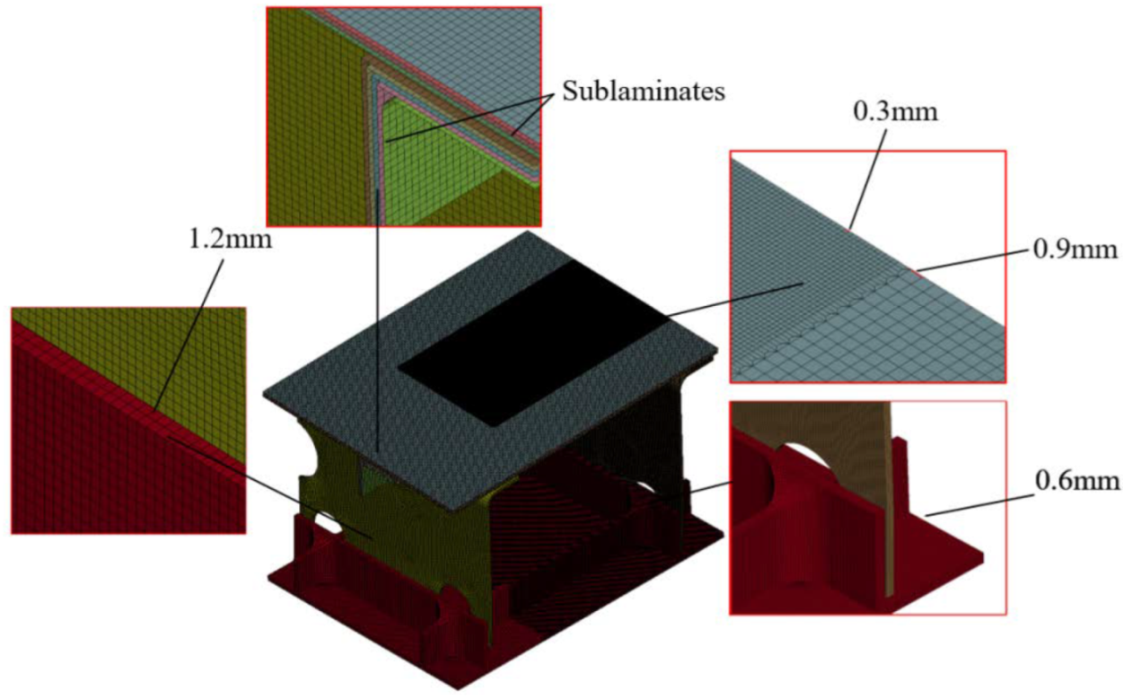
The structural metal part of the model mesh uses a hexahedral deca-node unit, and the composite part of the model consists of a 2D shell unit, with a single sub-layer containing three layers of actual layup information. * CONTACT_SURFACE_TO_SURFACE_TIEBREAK [15,16] is used between layers. The total number of model units for the air inlet Al alloy I-beam riveted structure is 241,437, and the total number of model units for the wing composite/Al alloy spacer structure is 1,099,060. In order to improve the overall computational efficiency and ensure the computational accuracy, the local mesh refinement method is used to divide the model into two density meshes, where the impact penetration part is encrypted mesh, and the two are connected by the trapezoidal transition mesh co-node method, as shown in Figure 20.
The fragment is set up with * CONTACT_AUTOMATIC_SURFACE_TO_SURFACE automatic face-to-face contact and * CONTACT_AUTOMATIC_SINGLE_SURFACE automatic single-sided contact between the fragment and the structure.
Typical damage modes of the composite bottom skin and stringer obtained by experiments and simulation are shown in Figure 21 and Figure 22, respectively. In terms of characteristic damage size, the diameter of openings and penetrations obtained from the simulation is close to that of the test. Since the composite simulation model uses 2D shell unit modeling, it cannot simulate the damage morphology of fiber fracture and spalling, and the Mat_Composite_Damage model does not consider the effect of temperature on overall damage. However, there is a small amount of fiber-melting phenomena in the actual test. Therefore, the characteristic damage size of a composite obtained from simulation is relatively small compared with the actual one, but the relative error is not big, and it can meet the requirements of battle damage size prediction to some extent. In terms of the Al alloy side damage morphology, the simulated results are in high agreement with the test, and the difference in feature size is small, as shown in Figure 23.
Figure 24 shows the kinetic energy curve of the fragment at a speed of 2400 m/s (kinetic energy = 6 kJ) from the composite side (Situation 2) and the metal side (Situation 3), respectively. The fragment is almost always linearly decaying during the intrusion. At a constant thickness, the kinetic energy dissipation of the fragment is greater for the carbon fiber composite layer, while the Al alloy layer is insensitive to the kinetic energy dissipation of the secondary penetration of the fragment, and the kinetic energy of the fragment decays rapidly to 0 during the secondary penetration of the composite layer.

4. Conclusions

A high-velocity impact test based on a two-stage light gas gun was carried out on an aircraft-typical composite/metal connecting structure (CFRP/AL). The simulated battle damage impact on the typical composite/metal connecting structure of the aircraft under different rendezvous conditions was achieved. This study aims to provide a reference for the rapid repair and assessment of aircraft battle damage and the design of aircraft structural survivability. The following conclusions are drawn from the study:
  • The composite laminate damage is characterized by stages, and its regional profile is mainly in the pattern of a combination of cylindrical (shear failure zone ) and circular truncated cones (tensile failure zone), and the upper and lower surfaces will produce different degrees of random spalling phenomena under the action of impact.
  • The established numerical model can well characterize the real damage morphology of both composites and the Al alloy. The damage sizes of predicted results are generally smaller than experimental results, which is within 8% on average.
  • The energy of carbon fiber debris dissipates quickly, while metal debris clouds contain considerable penetration capability, which will cause widely distributed secondary damage to the structure.
  • Different structural components have different energy dissipation capabilities. The kinetic energy of fragments decays by 4.3 kJ and 3.7 kJ, respectively, on the composite part and Al part at the first impact, and decays by 2.3 kJ and 0.4 kJ, respectively, on the composite part and Al part at the second impact. The composite part show stronger energy absorption properties, at the same thickness, than an Al alloy.

Author Contributions

Conceptualization, Y.W. and Y.H.; methodology, Y.W.; software, J.Y.; validation, Y.W.; formal analysis, J.Y.; investigation, T.Z.; resources, T.Z.; data curation, T.Z.; writing—original draft preparation, Y.W.; writing—review and editing, Y.W.; visualization, Y.W. and X.F.; supervision, H.Z.; project administration, Y.H.; funding acquisition, Y.H. All authors have read and agreed to the published version of the manuscript.

Funding

This research received no external funding.

Institutional Review Board Statement

The study was conducted in accordance with the Declaration of Helsinki, and approved by the Institutional Review Board (or Ethics Committee) of Aviation Engineering School, Air Force Engineering University.

Informed Consent Statement

Informed consent was obtained from all subjects involved in the study.

Data Availability Statement

Data will be made freely available on request.

Conflicts of Interest

The authors declare no conflict of interest.

References

  1. Horsfall, I.; Austin, S.J.; Bishop, W. Structural ballistic armour for transport aircraft. Mater. Des. 2000, 21, 19–25. [Google Scholar] [CrossRef]
  2. Sweetman, B. f-22 Raptor; Zenith Imprint: Neunkirchen, Germany, 1998. [Google Scholar]
  3. Appleby-Thomas, G.J.; Hazell, P.J. The impact of structural composite materials. Part 2: Hypervelocity impact and shock. J. Strain Anal. Eng. Des. 2012, 47, 406–418. [Google Scholar] [CrossRef]
  4. Miao, C.; Du, M.; Huang, L.; Zu, Z. Experimental research on hypervelocity impact characteristics of flexible anti-debris multi-shields structure. Manned Spacefl. 2017, 23, 173–176. [Google Scholar]
  5. Wang, Y.T.; He, Y.T.; Zhang, T.; Fan, X.H.; Zhang, T.Y. Damage analysis of typical structures of aircraft under high-velocity fragments impact. Alex. Eng. J. 2022, 62, 431–443. [Google Scholar] [CrossRef]
  6. Moritoh, T.; Kawai, N.; Matsuoka, S.; Nakamura, K.G.; Kondo, K.I.; Katayama, M. Hypervelocity impact experiments up to 9 km/s by a compact multi-stage light-gas gun. Int. J. Impact Eng. 2003, 29, 459–467. [Google Scholar] [CrossRef]
  7. Reddy, P.R.S.; Reddy, T.S.; Srikanth, I.; Madhu, V.; Gogia, A.K.; Rao, K.V. Effect of viscoelastic behaviour of glass laminates on their energy absorption subjected to high velocity impact. Mater. Des. 2016, 98, 272–279. [Google Scholar] [CrossRef]
  8. Reddy, P.R.S.; Reddy, T.S.; Mogulanna, K.; Srikanth, I.; Madhu, V.; Rao, K.V. Ballistic impact studies on carbon and e-glass fibre based hybrid composite laminates. Procedia Eng. 2017, 173, 293–298. [Google Scholar] [CrossRef]
  9. Cantwell, W.J.; Morton, J. Comparison of the low and high velocity impact response of CFRP. Composites 1989, 20, 545–551. [Google Scholar] [CrossRef]
  10. Johnson, G.R.; Cook, W.H. Fracture characteristics of three metals subjected to various strains, strain rates, temperatures and pressures. Eng. Fract. Mech. 1985, 21, 31–48. [Google Scholar] [CrossRef]
  11. He, Q.G.; Chen, X.W.; Chen, J.F. Finite element-smoothed particle hydrodynamics adaptive method in simulating debris cloud. Acta Astronaut. 2020, 175, 99–117. [Google Scholar] [CrossRef]
  12. Brar, N.; Joshi, V.; Harris, B. Constitutive model constants for Al7075-t651 and Al7075-t6. In Proceedings of the Aip Conference Proceedings, Nashville, TN, USA, 28 June–3 July 2009; pp. 945–948. [Google Scholar]
  13. Vignjevic, R.; Campbell, J.; Hughes, K.; Orłowski, M.; Garcea, S.; Withers, P.; Reed, J. Soft body impact resistance of composite foam core sandwich panels with unidirectional corrugated and tubular reinforcements. Int. J. Impact Eng. 2019, 132, 103320. [Google Scholar] [CrossRef]
  14. Zhu, W.; Xu, X. Experiment and finite element simulation in T300/QY8911 laminate under low-velocity impact. J. Mater. Sci. Eng. 2013, 31, 68–73. [Google Scholar]
  15. Dogan, F.; Hadavinia, H.; Donchev, T.; Bhonge, P.S. Delamination of impacted composite structures by cohesive zone interface elements and tiebreak contact. Cent. Eur. J. Eng. 2012, 2, 612–626. [Google Scholar] [CrossRef] [Green Version]
  16. Hallquist, J.O. LS-DYNA Keyword User’s Manual; Livermore Software Technology Corporation: Livermore, CA, USA, 2003; Volume 970, pp. 299–800. [Google Scholar]
Figure 1. Two-stage light gas gun and simulation of spherical fragments.
Applsci 12 09268 g001
Figure 2. Schematic of the two-stage light gas gun: 1: target chamber; 2: gas gun barrel; 3: sabot; 4: projectile; 5: optical beam blocking (OBB) system; 6: target; 7: flash lamp; 8: windows; 9: high-velocity camera.
Applsci 12 09268 g002
Figure 3. Tooling settings of the test piece. (a) Situation 1; (b) Situation 2; (c) Situation 3.
Applsci 12 09268 g003
Figure 4. Observation section setting of the target chamber.
Applsci 12 09268 g004
Figure 5. YXLON FF85 CT scanning system.
Applsci 12 09268 g005
Figure 6. Test piece of composite/Al alloy connecting frame structure.
Applsci 12 09268 g006
Figure 7. Schematic of composite layup method.
Applsci 12 09268 g007
Figure 8. Impact process of test piece of composite/Al alloy lapping frame structure.
Applsci 12 09268 g008
Figure 9. Typical shear damage mode of composite bottom skin.
Applsci 12 09268 g009
Figure 10. Typical damage mode of composite stringer.
Applsci 12 09268 g010
Figure 11. Damage mode of secondary damage of composite bottom skin.
Applsci 12 09268 g011
Figure 12. 3D CT damage player diagram. (a) Situation 1; (b) Situation 2; (c) Situation 3.
Applsci 12 09268 g012aApplsci 12 09268 g012b
Figure 13. Distribution of damaged area.
Applsci 12 09268 g013
Figure 14. Morphological features of the CFRP damage process. (a) Impact crater extrusion, (b) Shear intrusion, (c) Tensile intrusion, and (d) fiber fracture splashing.
Applsci 12 09268 g014
Figure 15. Morphology of damaged area in CFRP.
Applsci 12 09268 g015
Figure 16. Top skin damage in Situation 1.
Applsci 12 09268 g016
Figure 17. Top skin damage in Situation 2.
Applsci 12 09268 g017
Figure 18. Top skin damage in Situation 3.
Applsci 12 09268 g018
Figure 19. Finite element model of spherical fragments.
Applsci 12 09268 g019
Figure 20. Finite element model of the structure.
Applsci 12 09268 g020
Figure 21. Damages of composite bottom skin damage.
Applsci 12 09268 g021
Figure 22. Damages of composite stringer.
Applsci 12 09268 g022
Figure 23. Damages of metallic top skin.
Applsci 12 09268 g023
Figure 24. Curve of kinetic energy of fragments. (a) Curve of kinetic energy of fragments in Situation 2; (b) Curve of kinetic energy of fragments in Situation 3.
Applsci 12 09268 g024
Table 1. Al7075-T6 Johnson–Cook model and Mie–Gruneisen EOS parameters.
ParametersSymbol7075-T6
Johnson–Cook model parameters
Density (kg/m3)R02.81
Poisson’s ratioPR0.33
Shear modulus (GPa)E0.717
Static yield limit (MPa)A0.00546
Strain hardening modulus [13]B0.00678
Strain hardening exponentn0.71
Strain rate coefficient C0.35
Spall typeSPALL3
Failure parameters D1D1−0.068
Failure parameters D2D20.451
Failure parameters D3D3−0.952
Failure parameters D4D40.036
Failure parameters D5D50.697
Mie–Gruneisen EOS parameters
Constants CC0.535
Constants S1S11.34
Constants γGAMAO2.17
Table 2. T300/QY8911 material parameters [14].
ParameterSymbolT300/QY8911
DensityR01.6
Elastic modulus along the a directionEA1.32
Elastic modulus along the b directionEB0.073
Elastic modulus along the c directionEC0.073
ba/ca Poisson’s ratioPRBA/PRCA0.03
cb Poisson’s ratioPRCB0.31
Shear strengthSC0.00079
Tensile strength along the a directionXT0.049
Tensile strength along the b directionYT4.8
Compressive strength along the b directionYC0.002
Publisher’s Note: MDPI stays neutral with regard to jurisdictional claims in published maps and institutional affiliations.

