Article

Theoretical Analysis on the Effectiveness of Pipe Roofs in Shallow Tunnels

School of Civil Engineering, Lanzhou Jiaotong University, Lanzhou 730070, China
*
Author to whom correspondence should be addressed.
Appl. Sci. 2022, 12(18), 9106; https://doi.org/10.3390/app12189106
Submission received: 31 July 2022 / Revised: 4 September 2022 / Accepted: 8 September 2022 / Published: 10 September 2022
(This article belongs to the Section Civil Engineering)

Abstract

:
When a pipe roof is used as a pre-support for the surrounding rock in a shallowly buried tunnel, accurate prediction of the support effectiveness of the pipe roof is important in order to ensure the rationality of the pipe roof structure design. Based on analysis of pipe roof pre-support effects, considering the construction time of pipe roof structures and the interaction mechanisms between the steel pipes of the pipe roof and the surrounding rock, we establish a calculation model of the surrounding rock pressure acting on each steel pipe of the pipe roof on the semi-circular pre-support boundary. Through comparison and analysis with the measured results, we demonstrate that the calculation model for surrounding rock pressure and the calculation model for stress and deformation of the pipe roof are reasonable. According to the deformation coordination conditions between the steel pipe of the pipe roof and the surrounding rock on the pre-support boundary and alongside the Peck formula, we establish a theoretical analysis method for pipe roof pre-support effectiveness based on the indexes of the ground loss rate, settlement trough width, and maximum ground surface settlement, thereby realizing a quantitative evaluation of pipe-roof pre-support effectiveness. At the same time, the effects of steel pipe diameter, circumferential spacing, and excavation footage length on the pre-support effectiveness of the pipe roof are analyzed. The conclusions can be used as a basis for the design and optimization of pipe roofs and as a guide for the application of pipe roofs.

1. Introduction

Pipe roof pre-support technology is a commonly used auxiliary method in the construction of shallow underground tunnels. The purpose of this technology is to control stratum deformation and face stability in the process of construction and to ensure construction safety. Therefore, as the key technology for shallow underground tunnel construction, this technology is of important guiding significance to study the action mechanisms of a pipe roof and to reasonably evaluate its supporting effects.
A large number of scholars [1,2,3,4,5] have researched pipe shed pre-support technology through experimental research, numerical simulations, and theoretical analyses. In terms of the action mechanisms of pipe roofs, taking a single steel pipe of a pipe roof as the research object, some scholars [6,7,8,9] considered the restraint effects of initial support and rock masses in front of the tunnel face on the steel pipe of the pipe roof and analyzed the stress and deformation characteristics of the steel pipe of the pipe roof under the action of the surrounding rock pressure. On the basis of this experimental research, Zhou [10] put forward a scaffolding principle for pipe roofs and theoretically analyzed this principle’s spatial action mechanisms. A large number of scholars have carried out research on the effects of pipe shed pre-support. Based on the elastic foundation beam theory combined with practical engineering cases, Xu et al. [11] analyzed the influence of relevant parameters on the supporting effects of a pipe roof. M. Hisatake et al. [12] studied the pre-support effects of a pipe roof using a centrifuge model test. Using a model test, Guo [13] studied the influence of design parameters on the supporting effects of a pipe roof. Li et al. [14] published a comparative study on the pre-strengthening effects of a pipe roof and double-row conduit using a similar model test. Additionally, some scholars [15,16,17] established three-dimensional numerical models to study the pre-support effects of pipe roofs in detail.
As mentioned above, there have been many achievements in research on the mechanisms and effects of pipe-roof support. However, most of these research results have been summarized, and their theoretical depth did not reach the level needed to guide the design and construction of pipe roofs. Notably, to date, there is no quantitative theoretical description for the pre-support effects of pipe roofs. Therefore, it is impossible to construct a general design theory for a pipe-roof pre-supporting structure based on the classification of the surrounding rock. In this paper, we take a pipe roof in a shallow soft surrounding rock tunnel as the research object, work from the mechanism of pipe shed support, and construct a theoretical analysis model of pipe-roof pre-support effects based on the index of the formation loss rate and surface settlement. The purpose of this paper is to provide a theoretical basis for the design, optimization, and application of pipe roofs in shallowly buried weak surrounding-rock tunnels.

2. Establishment of a Pipe Roof Analysis Model

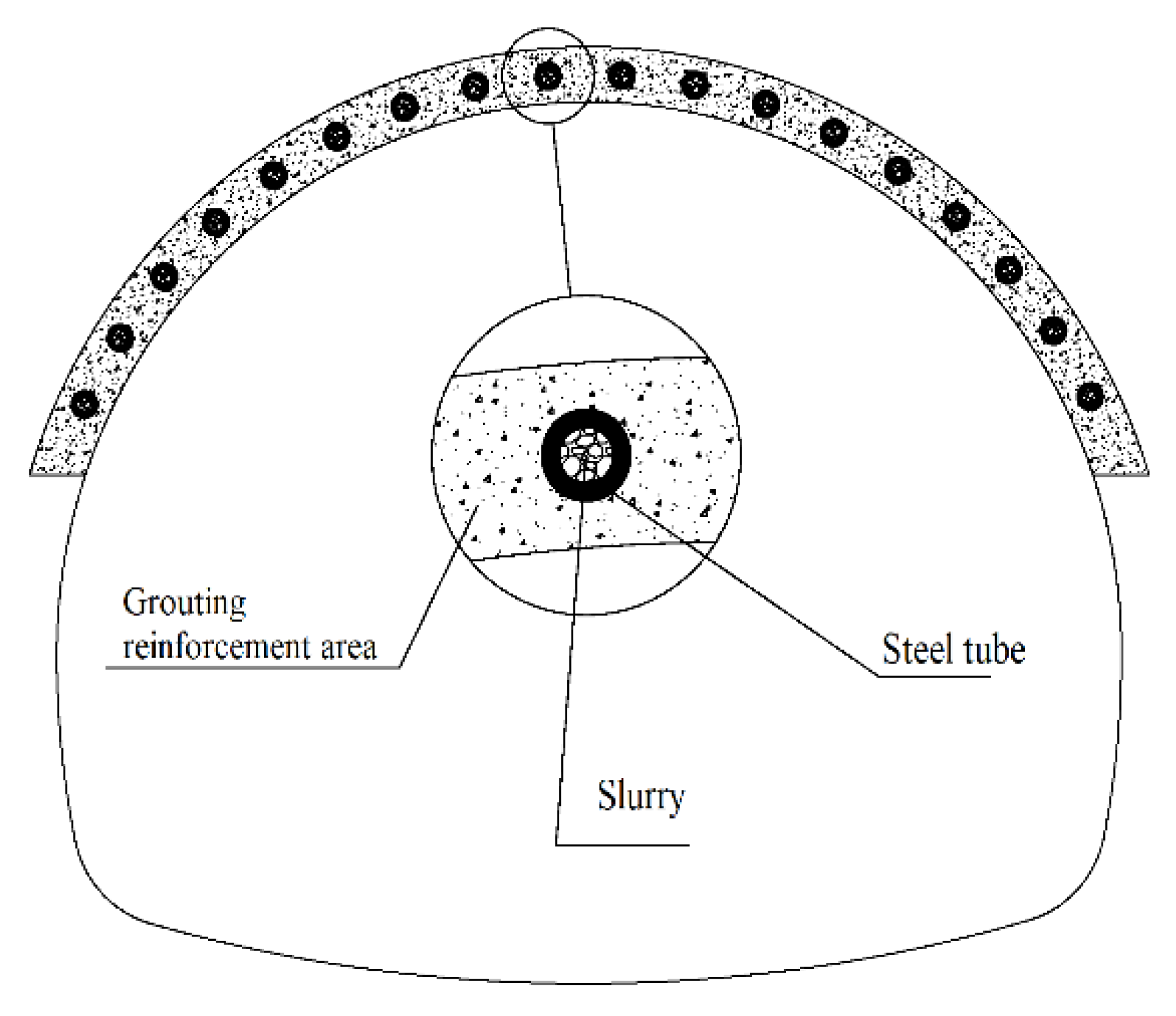
2.1. The Composition and Effects of the Pipe Roof

The pre-supported structure of a pipe roof is generally composed of a guide wall (or a set of arches), a guide pipe, a steel pipe, and a grouting reinforcement area. Scholars generally believe that the pre-support protection function of a pipe roof can be achieved by using a composite shell composed of a steel pipe and grouting reinforcement layer to withstand the surrounding rock pressure. Therefore, a composite shell composed of the steel pipes of the pipe roof and the rock mass of the grouting area is the main bearing member of the pre-supported protective structure of the pipe roof. A cross-sectional schematic diagram of the bearing members is shown in Figure 1.
The purpose of using pipe roof pre-support is to reduce the formation deformation caused by tunnel excavations, improve the stability of the palm surface and the excavation surface, and ensure the safety of construction. Therefore, the effect of pre-support of the pipe roof is mainly measured by deformation of the excavation surface, the stability of the palm surface, and the surface settlement. The tube shed carrying shell can transfer the ground stress that the palm face must bear to the initial support and deeper rock mass, improving the force state of the palm surface and thus also improving the stability of the palm surface. To control formation deformation, a theoretical analysis model of the support effects of the pipe roof based on the construction of force deformation considering the bearing of the pipe roof is established to realize a quantitative description of the deformation of the surrounding rock of the excavation surface and the settlement of the ground, so as to more accurately guide the design and construction of the pipe roof.
To study the role of the bearing shell composed of a steel pipe, slurry, and surrounding rock in the grout reinforcement area, the timing and construction conditions of the pipe roof should be considered. First, the steel pipe of the pipe roof and the grouting reinforcement area play specific roles in the pre-support system of the pipe roof. For the grouting reinforcement area, on the one hand, we found that in the grouting process of the pipe roof, due to the unevenness of the joint cracks of the rock mass, the effect of grouting reinforcement on improving the physical properties of the rock is not uniform. On the other hand, for both a pipe roof at the tunnel opening and a pipe roof in the tunnel, although a pulp stop section is reserved at the tail of the steel pipe of the pipe roof, a lack of uniformity often occurs due to the low-lying stress state of the rock mass above the slope of the tunnel opening or the palm. When the grouting pressure reaches a certain level, it will first form a crack in the area that penetrates the surface or palm surface such that the slurry flows out along the crack of this type. These cracks that penetrate the outside world make it difficult for the grouting pressure to meet the design requirements, resulting in a decrease in the reinforcement effects of the rock mass. Therefore, it is difficult for the surrounding rock in the reinforcement area to form a stable holding layer with bearing capacity. The role of this rock is mainly to improve the stiffness of the pre-support boundary and reduce the plastic deformation of the surrounding rock between the steel pipes of the pipe roof, thereby playing a protective role in the support boundary. Therefore, in the mechanical response analysis of the bearing shell, the role of the grouting reinforcement area as a bearing unit is ignored, and the combined beam composed of the steel pipe and slurry is used to withstand the surrounding rock pressure.

2.2. The Pressure of the Surrounding Rock Acting on the Pipe Roof

According to the above analysis of the effect of the pipe roof, the pre-supporting effect of the pipe roof is mainly reflected in the binding effects of the steel pipe on the surrounding rock. Therefore, in order to determine the role of the pipe roof in the transmission of loads, it is first necessary to clarify the size of the surrounding rock pressure on the steel pipe of the pipe roof.
When scholars [8,9] perform mechanical analysis on pipe tops based on elastic base beam models, the surrounding rock pressure is mostly calculated according to the loose surrounding rock pressure. However, the pre-support structure of the pipe roof is fundamentally different from the support structure of the tunnel cave. On the one hand, the surrounding rock pressure acting on the supporting structure of the cave body is the pressure that ultimately acts on the supporting structure after the stress state of the surrounding rock is redistributed through the two construction processes of excavation and support. The pipe roof’s advanced pre-support was installed in the formation according to the design requirements before the tunnel excavation. Thus, when the tunnel is excavated, all parts of the pipe roof’s advanced pre-support will be fully equipped with bearing capacity. On the other hand, the mechanical response to the steel pipe of the pipe roof is analyzed according to the Euler–Bernoulli beam theory based on the hypothesis of small deformation. Thus, it can be considered that the surrounding rock pressure acting on the steel pipe beam of the pipe roof does not change before and after deformation of the pipe roof.
Based on the above analysis, the following basic assumptions are made. (1) It is assumed that the boundary force of the rock mass to be excavated in the pre-support boundary under the initial ground stress state to the surrounding rock on the support boundary is equivalent to the binding force of the steel pipe of the pipe roof on the surrounding rock; (2) assuming that the interaction between the steel pipe of the pipe roof and the surrounding rock is extrusion, the binding direction of the steel pipe in the surrounding rock is the normal direction of the pre-support boundary.
In tunnel engineering, the pre-support boundary of the pipe shed is generally the arc boundary with a radius of R , and the pipe shed steel pipes in the support range of angle β are evenly arranged on the support boundary with a ring spacing of a . The pre-support protection boundary is discretized according to the position of the steel pipe of the pipe roof, and it is assumed that the distribution force of the excavated part of the rock mass on any small section of the boundary will be equivalent to the concentration force provided by the two adjacent steel pipes. Next, the equivalent binding force of the adjacent pipe roofs on each boundary to the surrounding rock is calculated, as shown in Figure 2. Finally, the equivalent binding force of each steel pipe on the adjacent boundary on both sides is superimposed, which provides the binding force of the steel pipe on the surrounding rock. According to Newton’s third law, the binding force of the steel pipe on the surrounding rock is equal to the amount of the surrounding rock pressure acting on the steel pipe, and the direction is positive, travelling inward along the radial direction.
If the excavation height of the palm face is H k , it is assumed that the surrounding rock at the arch foot of the tunnel does not undergo convergent deformation after excavation. First, the pipe roof is numbered. The steel pipe number of the vault pipe roof is 1, and the symmetrical numbers on the left and right sides are 2, …, i , …, n and …, i , …, n , as shown in Figure 2. The location of any point on the support boundary is represented by the center angle α corresponding to the arc between that point and the No. 1 steel pipe. The position of the ith steel pipe is
α i = i 1 θ
where i is the steel pipe number and θ is the center angle corresponding to the arc of the support boundary between any two steel pipes. Then,
θ = 2 arcsin a 2 R
where R is the boundary radius of the pre-support protection, m, and a is the ring spacing of the pipe shed, m.
When the height H of the support boundary vault to the ground is known, according to the geometric relationship, the height of the ith steel pipe to the ground, H i , can be found as follows:
H i = H + R 1 cos α i
Before the tunnel is excavated, the part of the rock mass to be excavated and the surrounding rock form a pair of balanced forces and reaction forces on the support boundary, with sizes equal to the initial ground stress. The initial ground stress of the shallowly buried tunnel is calculated according to the self-gravity stress, and the formation is assumed to be isotropic rock and soil. Then, the initial ground stress vertical component σ v and the horizontal component σ h at any point on the pre-support boundary are
σ v = γ H α σ h = λ σ v
where γ is the weight of the overlying rock of the tunnel, kN/m3; H α is the height of any point on the support boundary from the surface, m; λ is the lateral pressure coefficient of the surrounding rock, λ = μ / 1 μ ; and μ is the Poisson’s ratio of the surrounding rock.
The support boundary between the No. i 1 steel pipe and the No. i steel pipe is taken as the research object. According to the equilibrium conditions, the moment of point i 1 is taken, and M i 1 = 0 obtains
α i 1 α i σ v R 2 sin α sin α i 1 d α + α i 1 α i σ h R 2 cos α i 1 cos α d α q i , l R sin ( α i α i 1 ) = 0
The moment of point i is then taken, and M i = 0 obtains
α i 1 α i σ v R 2 sin α i sin α d α + α i 1 α i σ h R 2 cos α cos α i d α q i 1 , r R sin ( α i α i 1 ) = 0
From the control Equations (5) and (6), we obtain
q i , l = γ R ( H + R ) A 1 i + λ A 3 i γ R 2 A 2 i + λ A 4 i
q i 1 , r = γ R ( H + R ) A 5 i 1 + λ A 7 i 1 γ R 2 A 6 i 1 + λ A 8 i 1
where the A 1 i , A 2 i , A 3 i , A 4 i , A 5 i 1 , A 6 i 1 , A 7 i 1 , and A 8 i 1 positional functions are calculated according to the following equations:
A 1 i = 1 sin θ 2 sin θ 2 sin α i θ 2 θ sin α i θ A 2 i = 2 sin θ sin 2 θ 2 cos 2 α i θ 2 A 3 i = 1 sin θ θ cos α i θ 2 sin θ 2 cos α i θ 2 A 4 i = 1 sin θ sin θ 2 sin α i θ 2 sin α i + sin θ 2 cos α i θ cos α i θ 2 θ 2 A 5 i 1 = 1 sin θ θ sin α i 1 + θ 2 sin θ 2 sin α i 1 + θ 2 A 6 i 1 = 2 sin θ sin 2 θ 2 cos 2 α i 1 + θ 2 A 7 i 1 = 1 sin θ 2 sin θ 2 cos α i 1 + θ 2 θ cos α i 1 + θ A 8 i 1 = 1 sin θ θ 2 sin θ 2 sin α i 1 + θ 2 sin α i 1 sin θ 2 cos α i 1 + θ cos α i 1 + θ 2
where i = 2 , 3 ,   ,   n .
According to Equations (7) and (8), q 1 , r , q 2 , r , …, q n 1 , r and q 2 , l , q 3 , l , …, q n , l can be obtained separately. According to the calculation model shown in Figure 2, the amount of surrounding rock pressure acting on the No. i steel pipe is equal to the sum of the binding force of the No. i steel pipe on the two boundary intervals adjacent to that pipe, namely:
q i = q i , l + q i , r
where i = 2 , 3 ,   ,   n 1 .
Especially for the No. 1 steel pipes, depending on the symmetry available, we obtain
q 1 = 2 q 1 , r
For the No. n steel pipe, we can consider the right boundary interval of the No. n steel pipe as the intersection of the excavation height and the support boundary. The center angle corresponding to the boundary of this part is θ . Then,
θ = π 2 α n arcc sin R H k R
where H k is the excavation height, m. The control equation is derived according to the equilibrium conditions:
α n α n + θ σ v R 2 sin α n + θ sin α d α + α n α n + θ σ h R 2 cos α cos α n + θ d α q n , r R sin θ = 0
Derived from the controlling Equation (12), we obtain:
q n , r = γ R ( H + R ) A 5 n + λ A 7 n γ R 2 A 6 n + λ A 8 n
where A 5 n , A 6 n , A 7 n , and A 8 n are position functions calculated according to the following equations:
A 5 n = 1 sin θ θ sin α n + θ 2 sin θ 2 sin α n + θ 2
A 6 n = 2 sin 2 θ 2 cos 2 α n + θ 2 sin θ
A 7 n = 1 sin θ 2 sin θ 2 cos α n + θ 2 θ cos α n + θ
A 8 n = 1 sin θ θ 2 sin θ 2 sin α n + θ 2 sin α n sin θ 2 cos α n + θ cos α n + θ 2
According to the symmetry, the size of the surrounding rock pressure that can be found on each steel pipe on the left side is
q i = q i
where i = 2 , 3 , , n .

2.3. The Force and Deformation of the Steel Pipe of the Pipe Roof

Each steel pipe that comprises the shed will deform along the radial direction under the pressure of the surrounding rock. The authors in [18] studied in detail the mechanical response of a single steel pipe in the pipe shed considering the construction process under the action of surrounding rock pressure. The results for the surrounding rock pressure on each steel pipe of the pipe shed were substituted into the analytical expression of the force and deformation of a single steel pipe, and the deformation distribution along the longitudinal direction of each steel pipe was obtained. The results of this previous study serve here as a basis for further judging the effects of shed control formation deformation.

3. Evaluation of the Effect of Pre-Support of the Pipe Roof

3.1. The Index of the Pipe Roof Pre-Support Effect Evaluation

In the tunnel construction stage, the pipe shed is used for pre-support to control the stratum deformation and improve the stability of the excavation face. Therefore, it is important for the development of pipe shed design theory to select appropriate indicators to evaluate the effect of pipe shed pre-support. In shallow-buried tunnels, formation deformation is manifested by convergence of the surrounding rock and surface settlement. The effects of pipe shed advance support should also be evaluated based on these two aspects.
The convergent deformation at each key point of the tunnel section is usually used to evaluate the ability of the supporting structure to control surrounding rock convergent deformation. However, when this index is used to measure the effect of controlling surrounding rock deformation, the results vary greatly under different geological conditions and excavation sections. It is, therefore, difficult to establish a unified evaluation standard to compare the actual ability of the supporting structure to control surrounding rock deformation under different working conditions, which restricts the development of supporting structure design theory. In this paper, the ratio of the area of the intruded excavation contour to the area of the designed excavation section caused by radial convergent deformation of the surrounding rock under pre-support of the pipe shed is defined as the stratum loss rate. This index is used to measure the effect of the pipe shed on controlling surrounding rock deformation. This relative index can be used to compare and analyze the effects of pipe shed pre-support under different working conditions with relatively uniform standard results.
To date, the influence of shallow tunnel construction on surface settlement has not been solved theoretically. Therefore, this paper uses the Peck formula, which is often applied in subway construction, to calculate the distribution of surface subsidence deformation caused by tunnel construction. The maximum settlement of the section and the width of the settlement trough are used to evaluate the effect of the pipe shed on controlling surface settlement.

3.2. Evaluation Index Calculation Method

When analyzing the interaction between the pipe shed steel tube and surrounding rock, it is assumed that the steel tube and surrounding rock extrude each other. Thus, the convergent deformation of the surrounding rock on the pre-supported boundary can be considered equal to the deflection deformation of the pipe shed steel tube towards the tunnel. The deformation of the surrounding rock on the pre-supported boundary between the pipe shed steel tubes can be obtained via linear interpolation of the deformation of two adjacent steel tubes. The convergence deformation integral for the surrounding rock of any computed section can be used to obtain the formation loss of this section ( V l ):
V l = R θ i = 1 n 1 ω i + ω i + 1 θ 4 i = 1 n 1 ω i + ω i + 1 2 + R ω n θ ω n 2 4 θ
where R is the radius of the pre-support boundary, m; θ is the central angle corresponding to the supporting boundary arc between any two steel tubes, rad; θ is the central angle corresponding to the arc from the No. n steel pipe to the arch foot segment, rad; and ω i , ω i + 1 , and ω n are, respectively, the bending deformation of steel tubes i , i + 1 , and No. n in the calculated section.
Then, the formation loss rate of the calculated section η is obtained as
η = 2 V l π H k 2
where V l is the formation loss of the calculated section, m2, and H k is the excavation height of the palm face, m.
The surface settlement curve caused by excavation of the underground tunnel is commonly called the “settlement groove”. The Peck formula [19] is a classical formula widely used globally to estimate settlement curves [20,21,22]. Peck analyzed a large quantity of surface settlement data and related engineering data and concluded that the width i of the settlement trough was as follows:
i = H + H k 2 π tan 45 φ 2
where H is the buried depth of the pre-supported boundary vault, m; H k is the excavation height of the face, m; and φ is the internal friction angle of surrounding rock, °.
Then, the settlement value of any point on the surface corresponding to the calculated section can be obtained as
s y = s max e y 2 2 i 2
where y is the distance between the calculation point and the center point of the settlement curve, m; i is the width of the settling trough, m; and s max is the maximum surface settlement value of the calculated section, m. The calculation expression is
s max = V l 2 π i
The control effect of the pipe shed pre-support on stratum deformation can be quantitatively evaluated by calculating the stratum loss rate η , the span of the surface settlement trough i , and the maximum surface settlement s max by selecting the proper calculation interface along the tunnel’s longitudinal direction.

4. Case Calculation and Verification

The portal section of the Birch Ridge Tunnel [23] is dominated by silty clay. The depth of the tunnel is 2.7 m, and the degree of the surface slope is 15°. The mechanical parameters of the surrounding rock are shown in Table 1. The design adopts a pipe shed with a length of 30 m, a circumferential spacing of 40 cm, and a pipe diameter of 108 mm (the thickness is 6 mm) for pre-support. The pre-support radius is 7 m. The actual excavation height of the upper steps is 3 m, and the excavation input per cycle is 0.6 m. According to the method of equivalent stiffness [17], the equivalent moment of inertia is 6.68 × 10⁻⁶ m4, and the equivalent elastic modulus of elasticity is 7.89 × 10⁷ kPa.
Wang et al. [23] used field tests to obtain the flexural deformation of the steel pipe of the pipe roofs at the vault with the advancement of the palm face. The measured value shown in Figure 3 is the deformation of the steel pipe of the pipe roofs at the vault when the palm face is excavated to 22.5 m. Figure 3 shows the theoretical value for the deformation of the steel pipes in the pipe roofs at the vault when the palm surface is excavated to 22.5 m according to the calculational method for surrounding rock pressure proposed in this paper and the force deformation of the pipe roofs in Yu et al. [24].
Figure 3 shows that the theoretical size and distribution of the flexural deformation of the steel pipe at the vault are basically consistent with the measured data on site. Although the measured and calculated values show some differences at a distance of 22.5 to 27 m from the opening, their characteristics are basically the same. Therefore, it can be inferred that the error of the distance from the palm face to the opening of the hole is the reason for this difference and that the actual position of the palm face may be slightly farther than 22.5 m.
Contrast analysis demonstrates that the calculational method for the surrounding rock pressure proposed in this paper and the calculational method for force and deformation proposed in [18] correspond with actual working conditions. On this basis, it is reasonable to conduct a theoretical analysis of the pre-support effects of pipe roofs. The distribution of surrounding rock pressure borne by the pipe shed on different tunnel cross-sections is obtained by calculation as shown in Figure 4.
Figure 4 shows that as the tunnel progresses deeper, the burial depth of the tunnel becomes larger, and the size and distribution of the surrounding rock pressure acting on the steel pipes of each pipe roof also changes. The portal section of the tunnel was buried at a depth of 2.7 m. Additionally, the surrounding rock pressure on the steel pipe at the vault was 19.2 kN/m, and the surrounding rock pressure on the steel pipe at the arch springer was 39.4 kN/m, indicating a gradual increase from the vault to the arch springer. The tunnel was buried at a depth of 10.7 m and located 30 m from the portal section. The surrounding rock pressure on the steel pipe at the vault was 76.7 kN/m, and the surrounding rock pressure on the steel pipe at the arch springer was 97.7 kN/m. With an increase in depth, the position of the maximum surrounding rock pressure has a tendency to move to the spandrel between the arch springer on both sides. Here, the distribution of the surrounding rock pressure acting on each steel pipe on the cross-section and the rules following burial depth change can be seen. By introducing the calculated surrounding rock pressure into the stress and deformation calculation model of steel pipes, the deformation and formation loss ratio of steel pipes at different positions of each section can be obtained, as shown in Figure 5.
Figure 5 shows that in the early stage of excavation, the deflection deformation of the steel pipe and the formation loss ratio of each section increased rapidly. When the palm surface was excavated to 5 m, the deflection deformation of the steel pipe and the growth rate of the formation loss ratio became smaller and basically showed linear growth. The formation loss rate ultimately reached 5.5% at the end of the pipe roofs. This result also shows that in the early stages of excavation, the deformation of the steel pipe was not only affected by the change of the tunnel burial depth but also by the nonlinear deformation caused by the tunnel cycle construction process. Thus, the loss rate of the formation at this stage increased rapidly. When the deformation of the steel pipe accumulated to a certain extent, the deformation of the steel pipe was mainly affected by the change in burial depth, and the surrounding rock pressure increased linearly with a linear growth trend. Comparing the deflection deformation distribution of the pipe shed at three key positions (the vault, the haunch, and the arch springer) shows that, due to the distribution of the surrounding rock from the vault to the arch springer, the deflection deformation of the steel pipe gradually increased from the vault to the arch springer. However, the distribution of the deflection deformation of the steel pipe along the longitudinal length of the tunnel at different positions remained basically unchanged. The settlement distribution of the surface is as shown in Figure 6.
As shown in Figure 7, the width of the surface settlement trough is linearly distributed along the longitudinal direction of the tunnel after the excavation and support of the pre-support section of the pipe-roof. Here, the maximum settlement of the surface increases with an increase in the position of the opening and shows a converging trend, reaching 23.4 mm at the end of the pipe roofs.
In summary, the analysis model for pipe roofs proposed in this paper can be used to systematically predict the effects of pre-support for pipe roofs, enabling a theoretical analysis of the pre-support effect of the pipe shed. In a specific project, the design and construction parameters of the pipe roofs can be adjusted based on the theoretical prediction results to meet the requirements for controlling the deformation of the formation.

5. Discussion

Based on the above theoretical analysis of the pre-support effects of the pipe shed, we compared the control effects of the pipe shed on formation deformation under different design and construction parameters and proposed general conclusions for controlling formation deformation.
While keeping other design parameters unchanged, we investigated the distribution curves of the formation loss rate and the distribution curves of maximum surface subsidence for pipe diameters of 89, 108, 152, and 180 mm, as shown in Figure 8. The effect of pipe shed pipe diameter on pre-support was also studied. The equivalent section’s moment of inertia and the corresponding elastic modulus of the composite beam composed of a steel pipe and slurry are shown in Table 2.
Keeping the other design parameters unchanged, Figure 9 presents the distribution curves of the formation loss rate and maximum surface subsidence for pipe-shed design spacing of 40, 60, 80, and 100 cm. We also studied the effects of the circumferential spacing of the pipe shed on pre-support.
Keeping the other design parameters unchanged, Figure 10 shows the distribution curves of the formation loss rate and maximum surface subsidence for an excavation footage length per cycle of 0.5, 0.75, 1, 1.25, and 1.5 m. The influence of the excavation footage length on the pre-support effect was also analyzed.
Figure 8, Figure 9 and Figure 10 show that the ability of the pipe shed to control formation deformation is better when the pipe diameter is larger, the circumferential spacing is smaller, and the footage length of the cyclic excavation is shorter. To further study the correlation between steel pipe diameter, excavation depth, circumferential spacing, and formation deformation control, we investigated the influence of various design parameters on the formation loss rate using the formation loss rate at a distance of 30 m from the tunnel opening.
Figure 11 shows that, with the other conditions unchanged, a thicker pipe diameter corresponds to a smaller formation loss rate. However, with a continuous increase of the pipe diameter, the influence on the formation loss rate becomes increasingly smaller. This result indicates that when the diameter of the pipe used is small, replacing the steel pipe with one of a larger diameter can effectively improve the ability of the pipe shed to control the formation deformation. If a thicker steel pipe is selected and cannot control formation deformation, it is not economical to consider increasing the diameter of the steel pipe.
Figure 12 shows that, with the other conditions unchanged, the formation loss rate increases linearly with an increase in the hoop spacing of the tube shed. Reducing the circumferential spacing of the steel pipes can effectively improve the ability to control formation deformation.
Figure 13 shows that with the other conditions unchanged, the formation loss rate increases linearly with an increase in the footage length of the cyclic excavation. This result indicates that the footage length of cyclic excavation has an obvious influence on the pre-support effect of the pipe shed. During the construction process, the footage length of each cycle should be strictly controlled to ensure the pre-support effect.

6. Conclusions

(1)
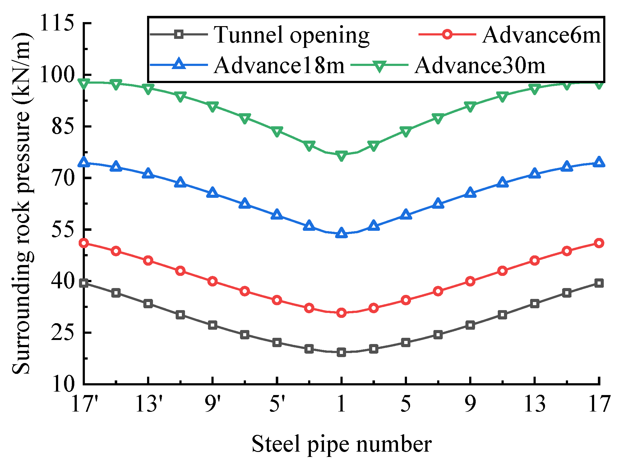
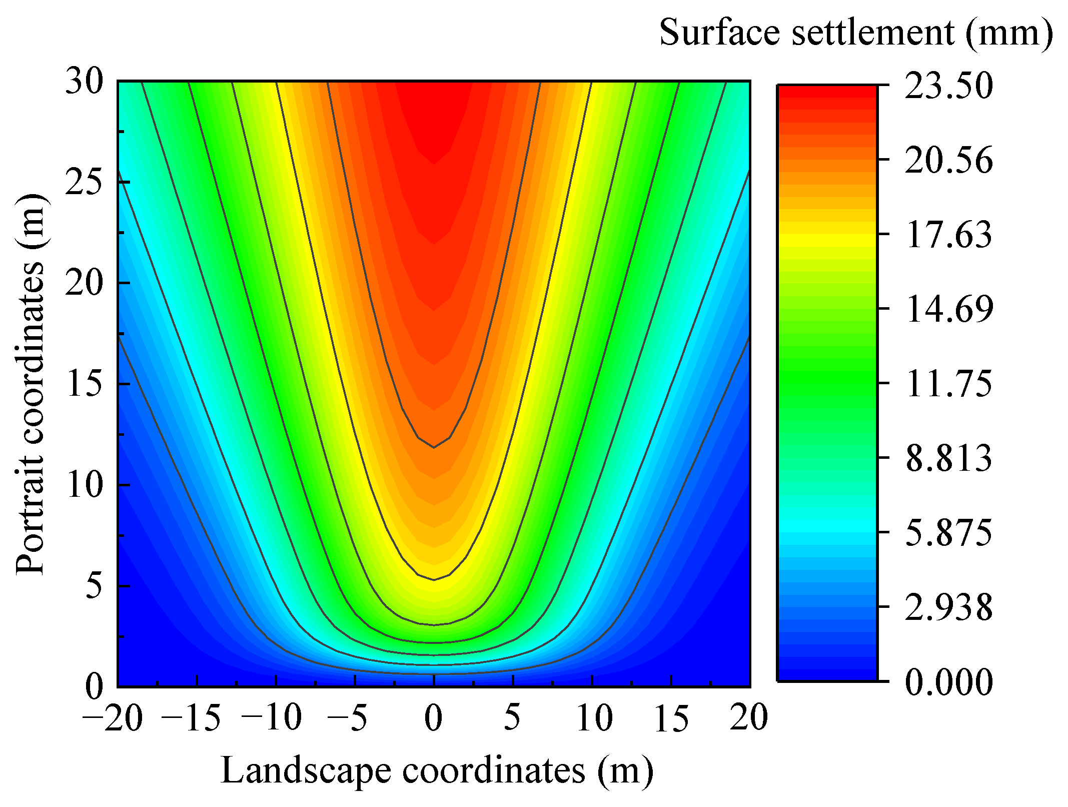
In this paper, a shallowly buried soft surrounding-rock tunnel is taken as the research object, and the mechanical calculation model of surrounding rock pressure on each steel pipe in the pipe shed is established by considering the application time of the pipe sheds. The distribution characteristics of the surrounding rock pressure, increasing gradually from the vault to the arch foot in the cross section of the tunnel, are discussed through a numerical example.
(2)
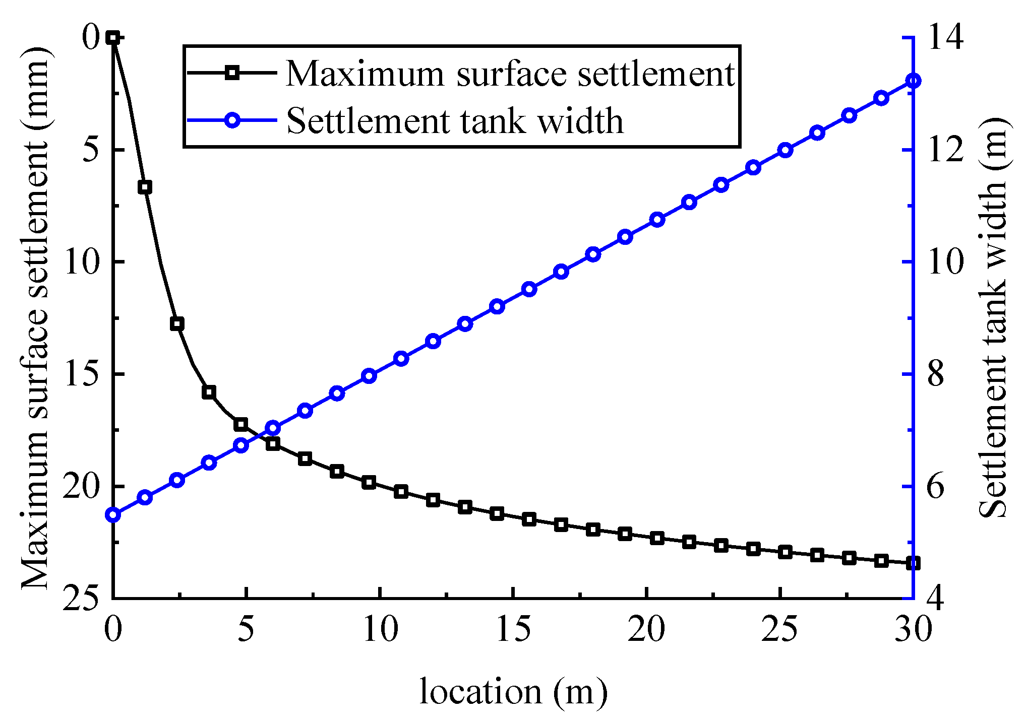
Based on the stress and deformation calculation model of pipe sheds shallowly buried in a soft surrounding rock tunnel and the Peck formula, a theoretical analysis model of pipe sheds’ advanced protection effect was constructed, and a theoretical analysis method of pipe sheds’ advanced protection effect was proposed, which took the stratum loss rate, settlement trough width, and maximum surface settlement as evaluation indexes.
(3)
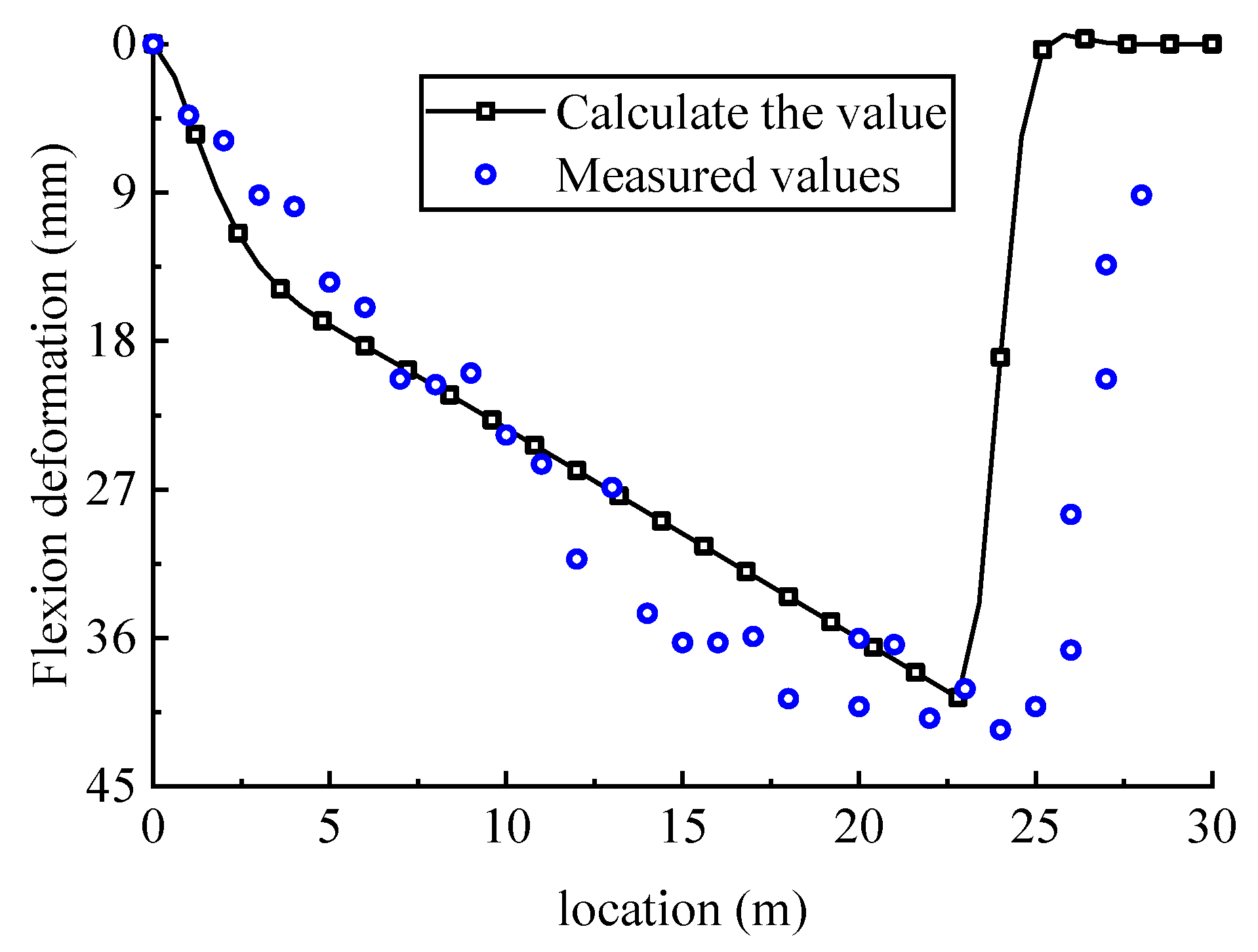
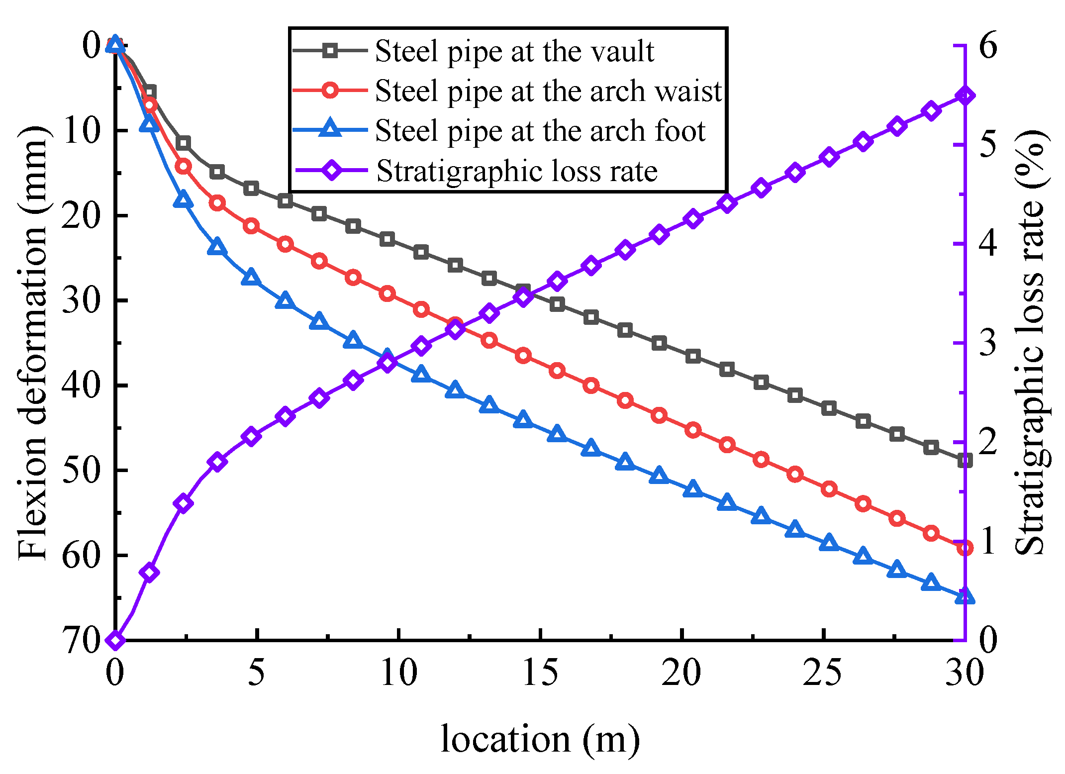
The theoretical calculations were demonstrated to be reasonable and accurate based on a comparative analysis with field-measured data of a pipe roof at the entrance of the Huapiling tunnel. On the basis of these results, we obtained the longitudinal distribution of surrounding rock deformation and surface settlement along the tunnel by theoretically calculating the control effect of surrounding rock deformation and surface settlement after completing the excavation and pre-support protection section of the Huapiling tunnel entrance.
(4)
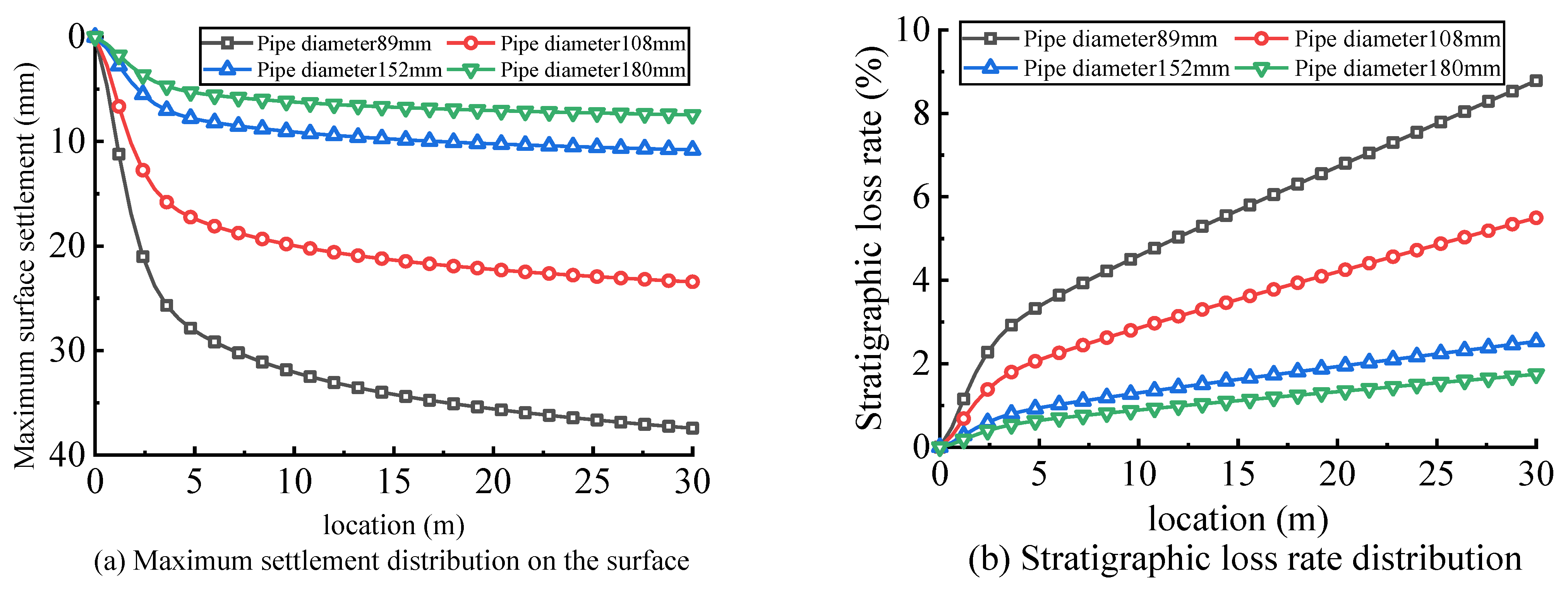
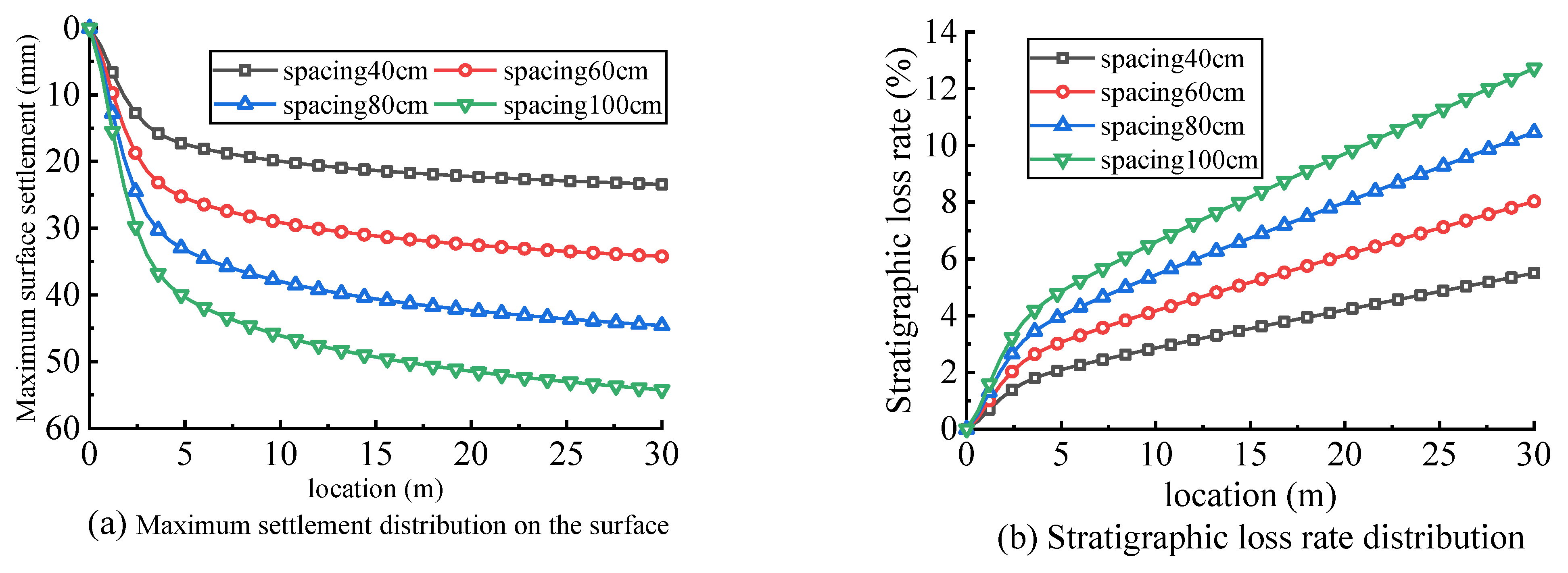
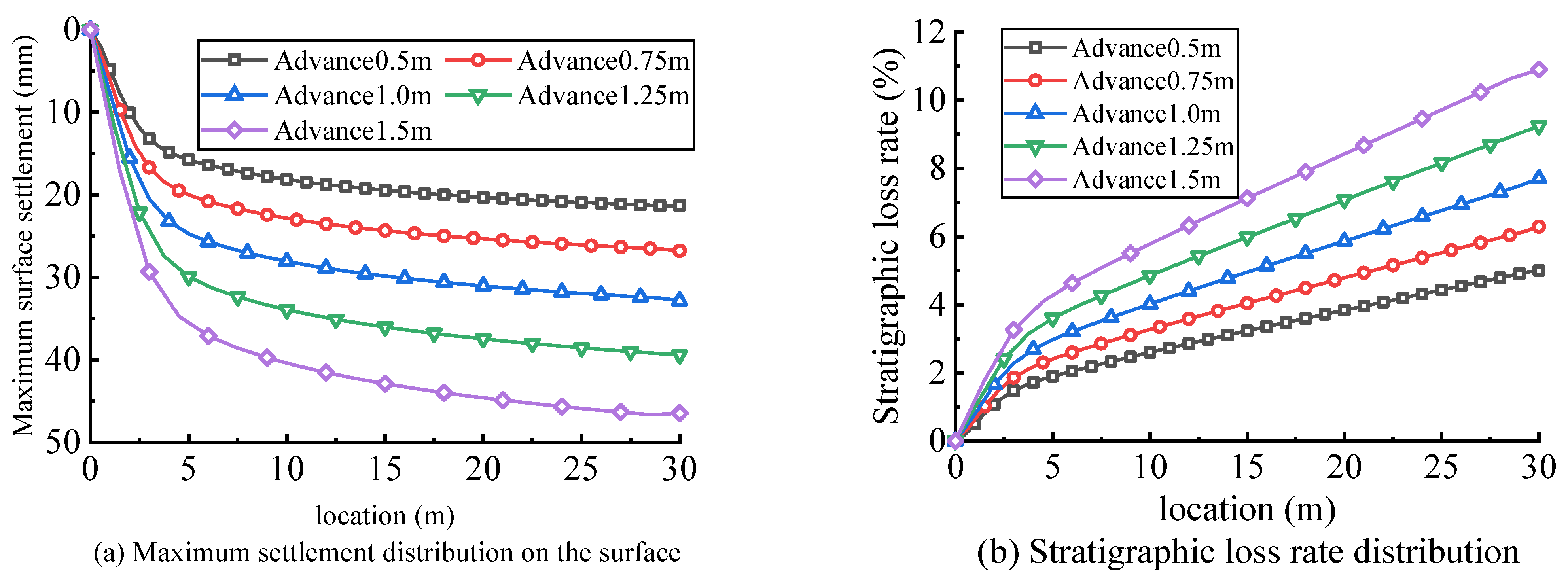
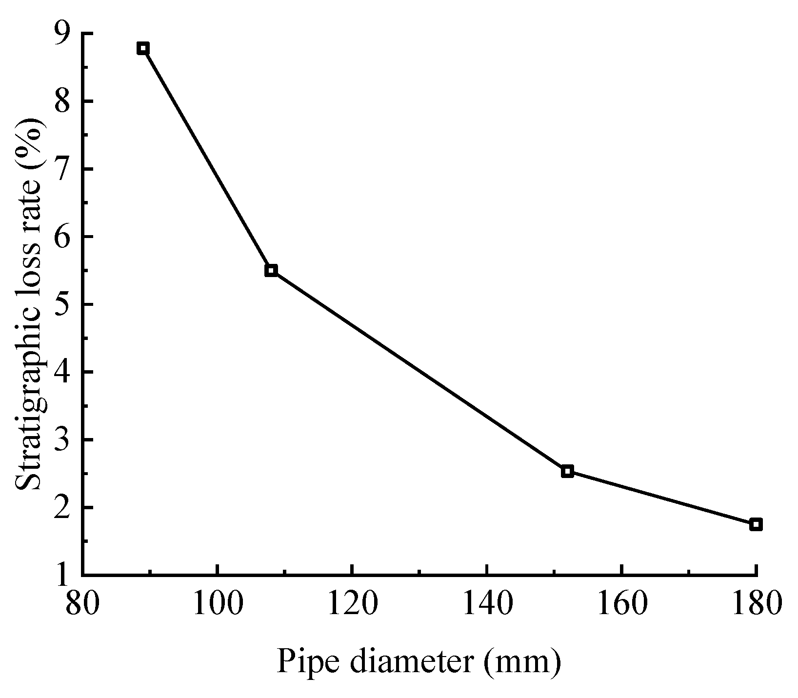
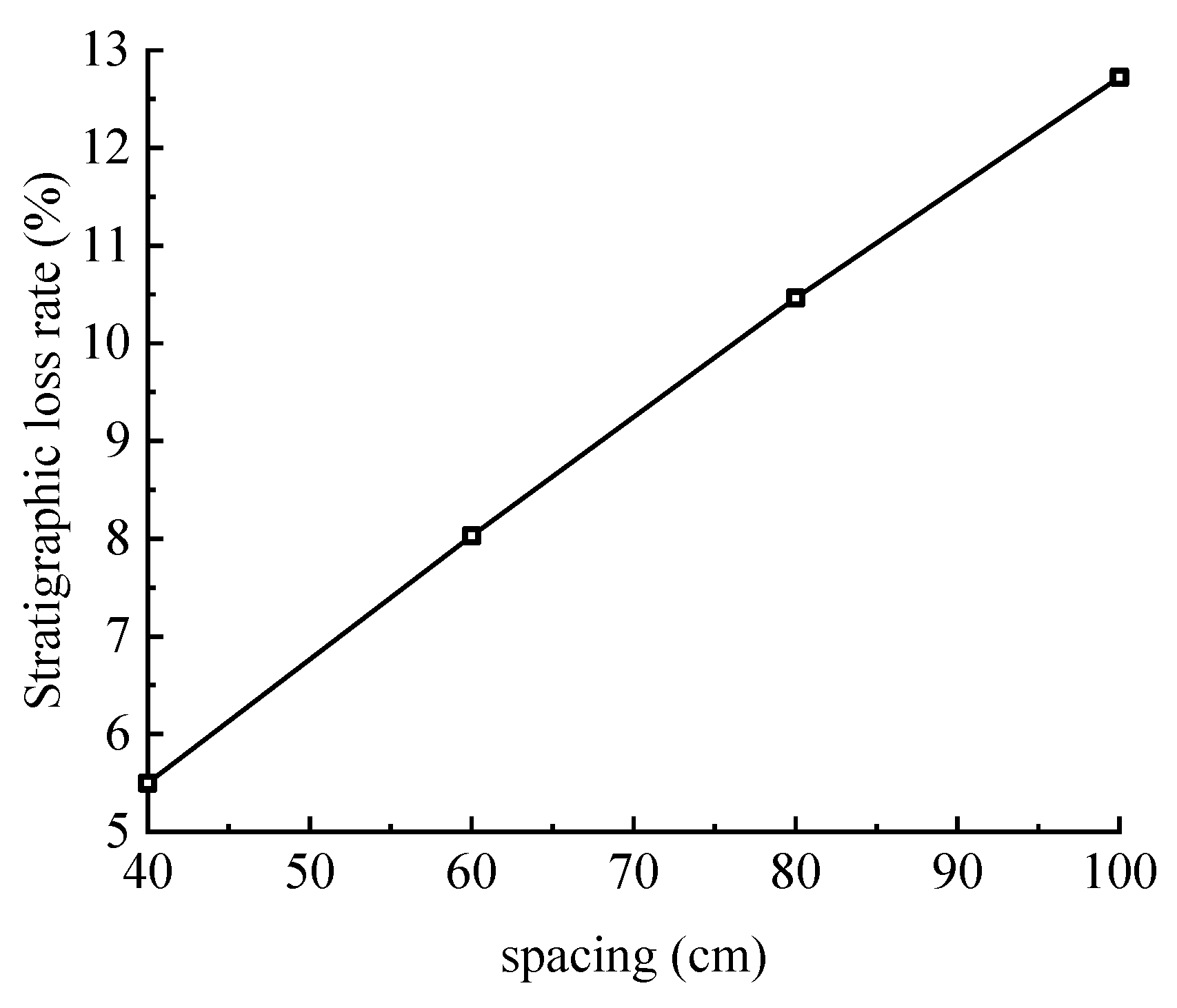
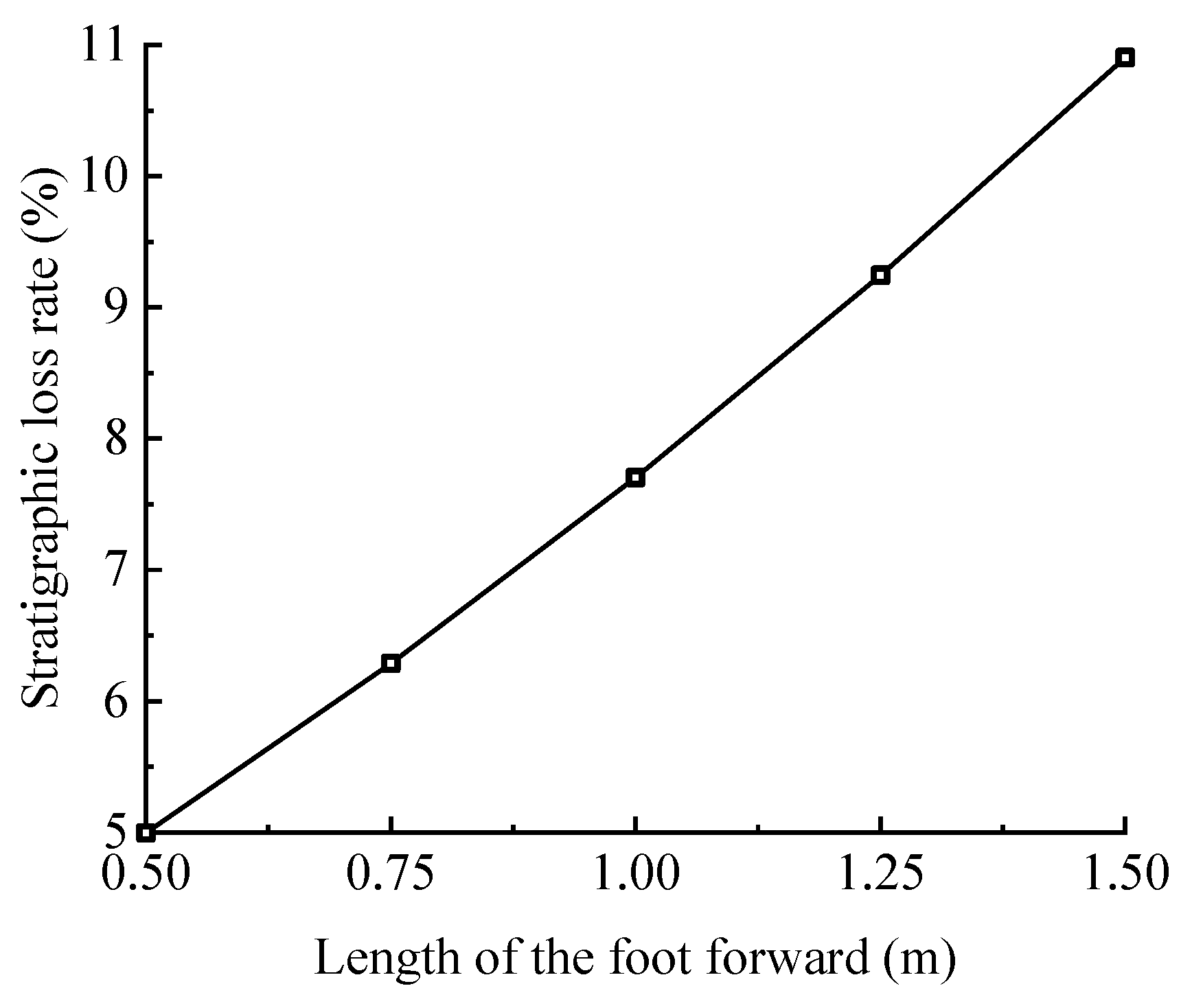
Guided by the effects of pre-support, the influence of the main design, and the construction parameters for the steel pipe diameter, we analyzed the impact of circumferential spacing and excavation footage length on the pre-support effects of the pipe roof. According to the analysis, the following conclusions can be drawn. The smaller the circumferential spacing and the smaller the excavation footage length, the better the ability of the pipe roof to control the surrounding rock deformation; when the pipe diameter is small, increasing the pipe diameter can effectively improve the ability of the pipe roof to control formation deformation, and when the pipe diameter is large, the effect on controlling formation deformation by increasing the pipe diameter will no longer be obvious.
(5)
In this paper, the pipe sheds of the shallowly buried soft surrounding-rock tunnel are taken as the research object, and the theoretical analysis method for pipe sheds’ pre-support effect and other related conclusions are put forward, which can provide a certain reference value for the design and construction of pipe sheds of similar projects.

Author Contributions

Conceptualization, Y.L. and S.Y.; data curation, Y.L. and W.W.; formal analysis, Y.L. and J.D.; investigation, Y.L. and J.D.; methodology, Y.L. and W.W.; validation, Y.L. and W.W.; writing—original draft preparation, Y.L.; writing—review and editing, Y.L. and S.Y. All authors have read and agreed to the published version of the manuscript.

Funding

This research was funded by the Chinese National Natural Science Foundation, grant number 52068044.

Institutional Review Board Statement

Not applicable.

Informed Consent Statement

Not applicable.

Conflicts of Interest

The authors declare no conflict of interest. The funders had no role in the design of the study; in the collection, analyses, or interpretation of data; in the writing of the manuscript, or in the decision to publish the results.

References

  1. Zhang, Z.; Li, H.; Liu, H.; Li, G.; Shi, X. Load transferring mechanism of pipe umbrella support in shallow-buried tunnels. Tunn. Undergr. Space Technol. 2014, 43, 213–221. [Google Scholar] [CrossRef]
  2. Yang, S.; Wang, M.; Du, J.; Guo, Y.; Geng, Y.; Li, T. Research of jacking force of densely arranged pipe jacks process in pipe-roof pre-construction method. Tunn. Undergr. Space Technol. 2020, 97, 103277. [Google Scholar] [CrossRef]
  3. Zarei, H.; Moarefvand, P.; Salmi, E.F. Numerical modeling of umbrella arch technique to reduce tunnelling induced ground movements. Environ. Earth Sci. 2019, 78, 291. [Google Scholar] [CrossRef]
  4. Luo, Y.; Chen, J.; Liu, B.; Chen, L.; Xie, J. Analysis of Pipe-Roof in Tunnel Exiting Portal by the Foundation Elastic Model. Math. Probl. Eng. 2017, 2017, 9387628. [Google Scholar] [CrossRef]
  5. Shi, Y.; Yang, J.; Wang, S. Sub-horizontal reinforcement of weathered granite before tunneling beneath a spillway. Int. J. Rock Mech. Min. Sci. 2014, 72, 283–293. [Google Scholar] [CrossRef]
  6. Zheng, J.J.; Zhang, R.J.; Yang, Q.N. Mechanical mechanism of piperoofs with variable coefficient of subgrade reaction in shallow tunnels. Chin. J. Geotech. Eng. 2009, 31, 1165–1171. [Google Scholar]
  7. Ding, Z.; Fu, J.; Liu, X.; Huang, J. Study of mechanical model for pipe roof in talus tunnel considering spatial effect. J. China Railw. Soc. 2018, 40, 121–127. [Google Scholar]
  8. Li, Z. Study on Mechanism and Design Method of Pipe Roof in Shallow Excavation Tunnel; Beijing University of Technology: Beijing, China, 2012. [Google Scholar]
  9. Song, Z.; Tian, X.; Zhou, G.; Li, W. Theoretical Analysis of Mechanical Behavior of Advanced Pre-support of Pipe-roof in Tunnel. China J. Highw. Transp. 2020, 33, 89–98. [Google Scholar]
  10. Zhou, S. Principles of pipe roof applied to shallow-buried tunnels in soft ground. Chin. J. Rock Mech. Eng. 2005, 14, 2565–2570. [Google Scholar]
  11. Xu, X.; Song, Z.; Li, H.; Tian, X.; Zhou, G. Unification of the Mechanical Model and Parameter Analysis of the Elastic Foundation Beam of Pipe-Roof. Front. Earth Sci. 2022, 10, 803670. [Google Scholar] [CrossRef]
  12. Hisatake, M.; Ohno, S. Effects of pipe roof supports and the excavation method on the displacements above a tunnel face. Tunn. Undergr. Space Technol. 2008, 23, 120–127. [Google Scholar] [CrossRef]
  13. Guo, X.; Zhang, H.R.; Meng, J.; Zhang, X.; Wang, M.; Zhu, Y. Model test to earth pressure distribution on pipe roof of tunnels as pre-supporting system in weak surrounding rock. Chin. J. Rock Mech. Eng. 2016, 35, 1214–1224. [Google Scholar]
  14. Li, H.Y.; Zhang, Z.Q.; Wang, Z.J. Similarity model test study of pre-reinforcement measures of shallow tunnel with large cross-section. Rock Soil Mech. 2012, 33, 133–138. [Google Scholar]
  15. Morovatdar, A.; Palassi, M.; Ashtiani, R.S. Effect of pipe characteristics in umbrella arch method on controlling tunneling-induced settlements in soft grounds. J. Rock Mech. Geotech. Eng. 2020, 12, 984–1000. [Google Scholar] [CrossRef]
  16. Bagherzadeh, P.; Goshtasbi, K.; Kashef, M. Umbrella arch method performance, structural behavior and design elements utilizing in collapsing zones. Environ. Earth Sci. 2020, 79, 521. [Google Scholar] [CrossRef]
  17. Xiao, J.Z.; Dai, F.C.; Wei, Y.Q.; Xing, Y.C.; Cai, H.; Xu, C. Analysis of mechanical behavior in a pipe roof during excavation of a shallow bias tunnel in loose deposits. Environ. Earth Sci. 2016, 75, 293. [Google Scholar] [CrossRef]
  18. Wang, W.; Lei, X.T.; Li, D.W. Prediction method for stress and deformation of pipe roofs and its engineering application. Chin. J. Geotech. Eng. 2022, 44, 325–359. [Google Scholar]
  19. Peck, R. Deep Excavation and Tunneling in Soft Ground. In Proceedings of the 7th International Conference Soil Mechanics and Foundation Engineering, Mexico City, Mexico, 21 August 1969; Sociedad Mexicana de Mecánica: Mexico City, Mexico, 1969; pp. 225–290. [Google Scholar]
  20. Osman, A.; Bolton, M.; Mair, R. Predicting 2D ground movements around tunnels in undrained clay. Géotechnique 2006, 56, 597–604. [Google Scholar] [CrossRef]
  21. Duan, S.K.; Huang, L.; Bao, Z.; Shen, P. Application of modified Peck formula in surface subsidence prediction of Changsha subway tunnel construction. J. Nat. Disasters 2013, 24, 164–169. [Google Scholar]
  22. Zhu, C.H. Control of surface settlement by considering shield tunneling technology. KSCE J. Civ. Eng. 2017, 21, 2896–2907. [Google Scholar] [CrossRef]
  23. Wang, D.; Yuan, J.; Li, J.; Peng, X.; Wu, Z.; Liu, W.; Wang, H. Deformation prediction of pipe roof in shallow soft portal section of tunnels considering construction feature. Chin. J. Rock Mech. Eng. 2017, 36, 716–724. [Google Scholar]
  24. Yu, L.; Yang, N.; Lyu, C.; Wang, M.; Tong, J. Study on Equivalent Elastic Modulus of Steel Reinforced Concrete Frame. Railw. Eng. 2018, 58, 42–45. [Google Scholar]
Figure 1. Schematic diagram of the bearing members of a pipe roof.
Applsci 12 09106 g001
Figure 2. Schematic diagram of a cross section of the pipe roof pre-support.
Applsci 12 09106 g002
Figure 3. Comparison between the calculated value and the measured value of pipe roof deformation.
Applsci 12 09106 g003
Figure 4. Surrounding rock pressure distribution of steel pipes on different sections.
Applsci 12 09106 g004
Figure 5. Distribution curve of steel pipe deflection deformation and ground loss rate.
Applsci 12 09106 g005
Figure 6. Cloud map of surface settlement distribution.
Applsci 12 09106 g006
Figure 7. Distribution curve of the width of the surface settlement trough and maximum surface settlement.
Applsci 12 09106 g007
Figure 8. Influence of pipe diameter on formation deformation distribution.
Applsci 12 09106 g008
Figure 9. Influence of circumferential spacing on formation deformation distribution.
Applsci 12 09106 g009
Figure 10. Influence of the excavation footage length on the formation deformation distribution.
Applsci 12 09106 g010
Figure 11. Relationship curve between the pipe diameter and formation loss rate.
Applsci 12 09106 g011
Figure 12. Relation curve between circumferential spacing and formation loss rate.
Applsci 12 09106 g012
Figure 13. Relation curve between the excavation footage length and formation loss rate.
Applsci 12 09106 g013
Table 1. Mechanical parameters of the surrounding rock.
ParameterBase Bed Coefficient (kN/m3)Foundation Shear Modulus (kN/m)Unit Weight (kN/m3)
Value28,000280017.5
Table 2. Combined section parameters of different pipe diameters.
Pipe Diameter (mm)89108152180
Equivalent Moment of Inertia (m4)3.08 × 10−66.68 × 10−62.6 × 10−55.15 × 10−5
Equivalent Modulus of Elasticity (kPa)9.24 × 1077.89 × 1075.89 × 1075.07 × 107
Publisher’s Note: MDPI stays neutral with regard to jurisdictional claims in published maps and institutional affiliations.

