1. Introduction
With the further development of rail transit, the excavation projects of foundations adjacent to shield tunnels are becoming more common. For example, the nearest distance between the section tunnel of Shanghai Rail Transit Line 1 and the building foundation pit is only 7 m [
1]. The closest distance was about 11 m between a construction foundation pit and Hangzhou Metro Line 1 [
2]. The unloading effect on the sidewall due to the excavation of foundation pit leads to the deformation of the enclosure structure, which will generate additional loads on the adjacent tunnel. The excessive loads will endanger the safety of the tunnel. It has been reported an engineering case in which the tunnel section of the Panchiao line was damaged due to adjacent foundation pit excavation during the construction of the Taipei MRT system [
3]. As a result, it is significant to predict the deformation of ad-jacent shield tunnel due to the foundation pit excavation.
Such problems have been concerned domestically and internationally. The main research methods include theoretical calculation [
4,
5,
6], numerical simulation [
7,
8], centrifuge test [
9] and measured data analysis [
10,
11]. However, the theoretical calculation methods are almost based on the stress release method. The construction of foundation pit is regarded as the process of soil stress release. The additional stress acting on the side shield tunnel caused by sidewall unloading is calculated to establish the synergistic deformation equation of tunnel and soil for obtaining the deformation of the side shield tunnel. Zhang et al. [
4] calculated the extra stress on the shield tunnel adjacent to a foundation pit engineering based on the Mindlin solution, the Winkler foundation model was introduced to obtain the calculation equation of tunnel displacement and internal force. However, the study considered that the stresses on the four sidewalls of the foundation pit were all released, which was inconsistent with the engineering practice. Wei and Zhao [
12] further considered the partial release of foundation pit sidewall stress under the action of retaining structure. The stress loss rate of enclosure structure β is introduced in the research. However, the deformation of the retaining structure was not considered in the study. Zhang et al. [
13] predicted the deformation form of the enclosure structure as “bow-shaped” to get the sidewall unloaded. However, the sidewall unloading stress could not be verified.
The virtual image technique [
14] has been used to calculate soil displacement caused by tunnel construction or foundation pit excavation, because it can make full use of the field monitoring data and precisely calculate the soil displacement at any point caused by soil loss. Based on the virtual image technique, Verruijt et al. [
15] obtained the soil deformation due to tunnel excavation considering the compressibility of soil. Xu and Poulos [
16] considered the deformation of the enclosure structure as a quadratic parabola to calculate the soil displacement at any point outside the foundation pit due to the excavation based on the virtual image technique. Some scholars further considered the impact of soil deformation caused by construction activities on adjacent structures. Zhang et al. [
17] obtained the displacement of soil due to foundation pit construction and then get the displacement of the adjacent pile foundation on the Winkler foundation model. Zhang et al. [
18] further considered the Kerr foundation model to assess the impact on the pile adjacent to the foundation pit more accurately. Yet, the virtual image technique has not been applied to analyze the effect on shield tunnels beside the foundation pit excavation.
To correctly evaluate the impact on the shield tunnel because of the foundation pit construction, a simplified analytical approach that can consider the deformation of the enclosure structure is presented in this study, which has the following innovations:
- (1)
At present, most of the theoretical calculation methods can not consider the influence of the deformation of the retaining structure on the unloading of the foundation pit. Based on the virtual image technique, the foundation pit unloading model considering the deformation of the retaining structure is established.
- (2)
The stress release method takes the stress as an additional load, but the stress cannot be verified. Based on the virtual image technique, the soil deformation is taken as an additional load, and the calculated soil deformation can be verified in the engineering.
- (3)
At present, most shield tunnel models can not consider the assembly characteristics of segment rings. We introduce the deformation model of the shield tunnel, considering rotating and dislocation [
13] to further study the dislocation and rotation law of the shield tunnel caused by foundation pit excavation.
This paper selects typical engineering examples to compare the calculated values with the measured values to verify the reliability of this method. The factors include the deformation of the enclosure structure, the distance between the adjoining shield tunnel and the enclosure structure, and the buried depth of the shield tunnel.
2. Mechanical Model Establishment and Equations Derivation
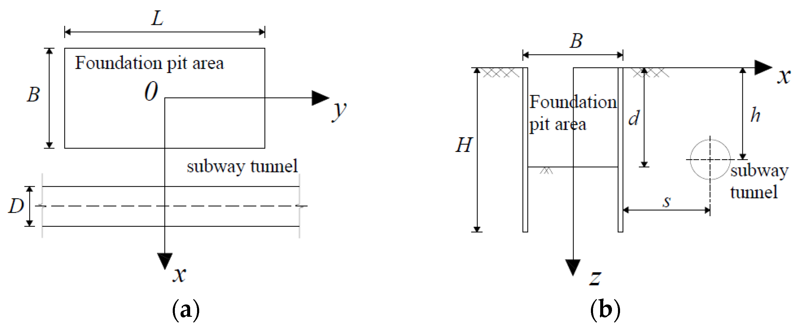
As
Figure 1 shows, the foundation pit is rectangular in shape whose length is
L, width is
B, and depth of excavation is
d. The height of the enclosure structure is
H. Establish a coordinate system at the center
O of the foundation pit. Establish a spatial coordinate system: The
x-axis and
y-axis are perpendicular and parallel to the tunnel axis, respectively, and the positive direction of the
z-axis is vertically downward. The distance between the enclosure structure and the shield tunnel axis is
s, the buried depth is
h, and
D is the outer diameter of the segment.
2.1. Prediction Model of Deformation of Enclosure Structure
The design theory of controlling deformation has been widely applied in foundation pit engineering. The deformation of enclosure structure is taken as the control parameter to control the effect on the adjacent shield tunnel because of the foundation pit excavation. This section establishes a prediction model for the deformation of the enclosure structure suitable for the internal bracing system.
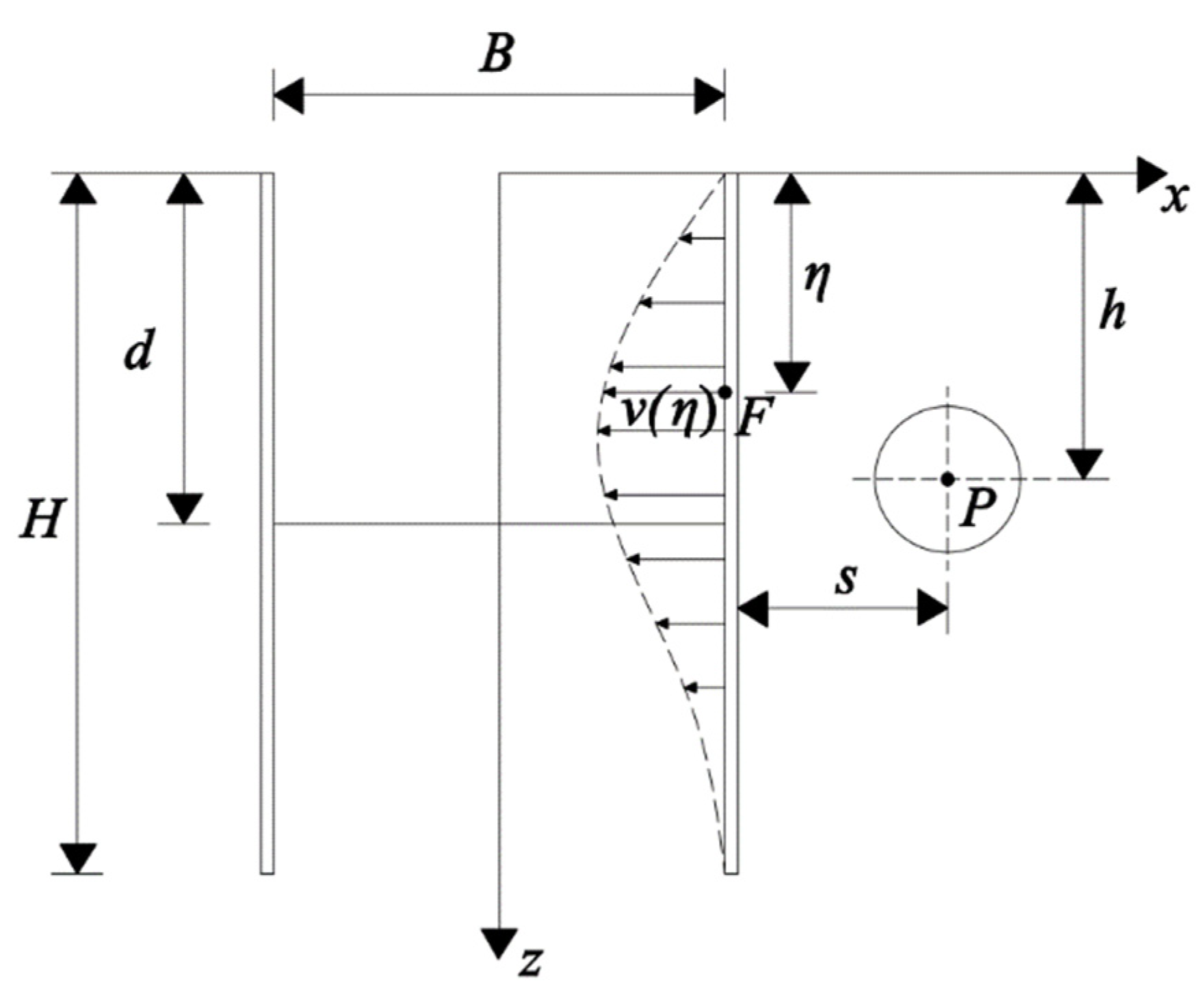
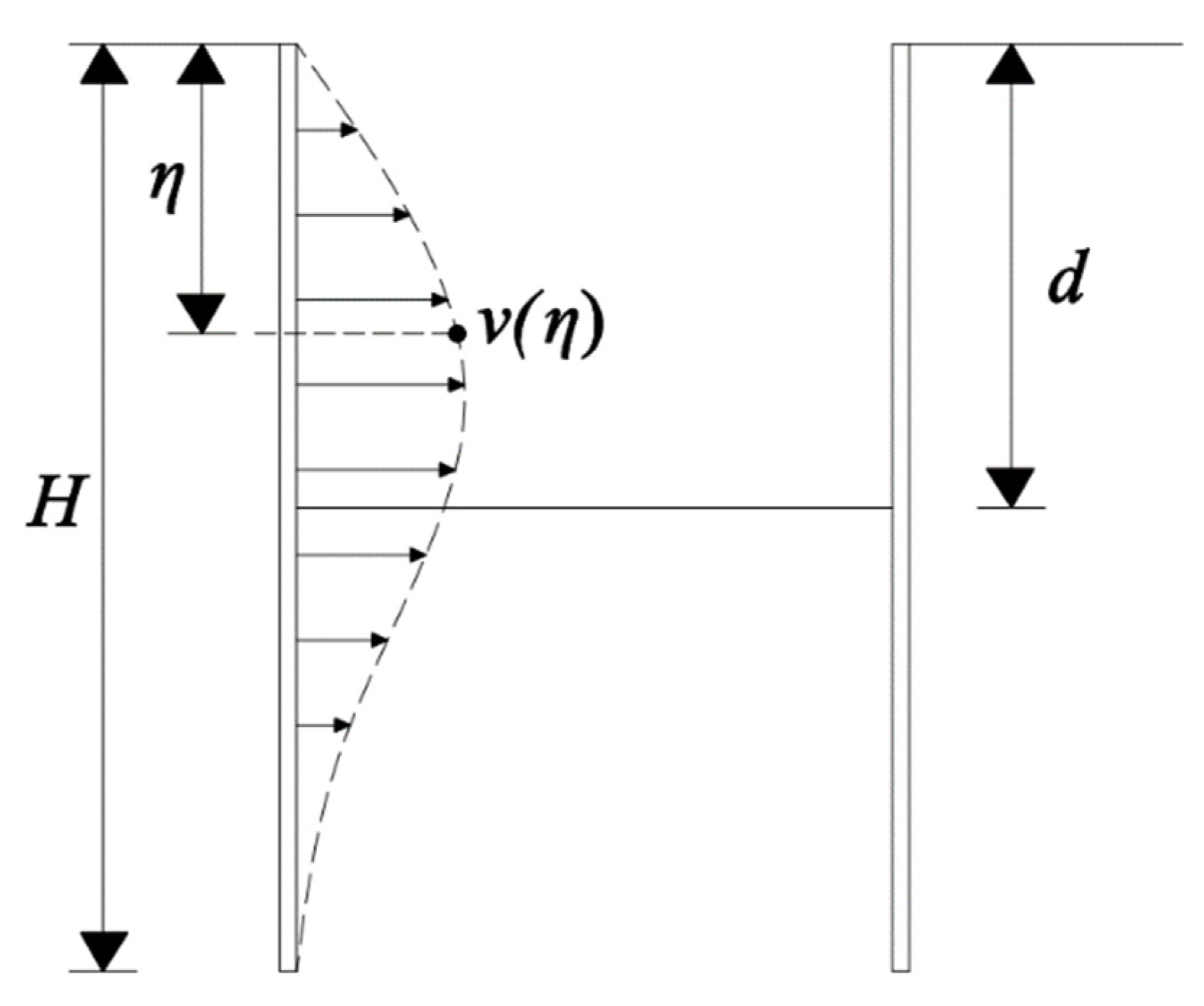
Figure 2 means the deformation diagram of the enclosure structure. The enclosure structure is deformed due to foundation pit excavation, in which:
H is the height of the enclosure structure. The depth of excavation is
d.
η is the embedded depth at any point on the sidewall of the retaining structure. Set the displacement of any point on the enclosure structure toward the foundation pit as
v(
η).
Liu et al. [
19] fit the deformation increment of the enclosure structure with piecewise cosine function. According to the statistics of existing engineering, the deformation increment of the internal bracing enclosure structure reaches the maximum close to the excavation surface. The increment of the enclosure structure deformation is:
where:
is the deformation increment of the enclosure structure at depth
η due to the excavation of
i-th soil layer, the depth reached after the excavation of
i-th soil layer is
di.
δmaxi is the maximum deformation increment of the enclosure structure due to the excavation of the
i-th layer.
The maximum cumulative deformation is commonly taken as the control required for the deformation of the enclosure structure in engineering applications. Referring to the research of Zhang et al. [
20], the ratio of the maximum deformation of the enclosure structure to the depth of excavation is selected as the control parameter in the calculation process in this study. Assume that the cumulative deformation of each layer meets the control value, so the maximum increment of deformation due to the
i-th layer excavation is:
when the excavation depth reaches
d after
n-th layers of excavation, the deformation at any point on the enclosure structure is:
where the depth of excavation is the sum of the excavation thickness of each previous layer:
.
2.2. Calculation of Soil Displacement at Shield Tunnel Axis
Sagasteta [
14] proposed the virtual image technique in 1987 and derived the equation of the distribution law of the surrounding soil displacement field caused by stratum loss at any point in the elastic half-space. As shown in
Figure 3, the basic analysis steps are as follows:
- (1)
Ignoring the surface of the semi-infinite space, this hole is called a positive source, and the problem will be transformed into the space under the infinite space. The solution of the displacement field of the soil layer in the gap will generate the normal stress σ0 and the shear stress τ0 on the surface of the infinite space.
- (2)
A fictitious volume expansion of the same size is set at the mirror image position of the void in the infinite space, and the opposite is called a negative source hole. The symmetrical negative source will generate positive stress σ0 and shear stress τ0 on the original infinite surface. Under the action of the positive source hole and the negative source hole, the normal stress on the original surface that does not exist can be offset.
- (3)
The positive and negative source holes above are superposed, and the normal stress counteracts each other, while the shear stress is converted to 2τ0. When the shear stress 2τ0 is inversely applied to the surface of the original semi-infinite body, and the above three steps are superimposed, the solution of the displacement field under the layer loss on the surface of the semi-infinite body can be obtained.
Based on this method, this study calculates the soil displacement because of the deformation of the enclosure structure. It adopts a certain simplification of the displacement mechanism of the soil loss. The hypothesizes are as follows:
- (1)
No consideration of pore water pressure and soil consolidation;
- (2)
The soil is incompressible, and the soil displacement field of the is only caused by the soil loss;
- (3)
Each section of the envelope structure deforms in the same size.
The calculation model of the virtual image technique is shown in
Figure 4. The displacement at point
p (
x1,
z1) on the tunnel axis along the
X-axis produced by the sink of the radius
a at point
F (
B/2,
η) is:
where
, indicates the distance between point
F and point
p.
Since Equation (4) is the displacement expression of infinite space, but the construction site is a semi-infinite space; it is necessary to transform the problem of solving the infinite space into the problem of solving a semi-infinite space. Therefore, the point
F (
B/2,
η) is mirrored as point
F’ (
B/2, −
η), where an equal volume expansion occurs. The displacement at point
p (
x1,
z1) on the tunnel axis along the
X-axis produced by the source of the radius
a at point
F’ (
B/2, −
η) is:
where
, which indicates the distance between point
F’ and point
p.
During the establishment of Equation (4), the shear strain
γ will be generated on the ground:
Then, the additional shear stress generated on the surface is:
where
G is the shear modulus of the soil.
Adding the inverse sign of the additional shear stress to the surface, the displacement along the
X-axis produced by the shear stress at point
p is:
In summary, the component of the soil displacement along the
X-axis produced by the sink with radius
a at point
F in the semi-infinite space at point
p is:
Considering that the outside of the enclosure structure should be a half-space, according to the symmetry, this problem can be transformed into the solution of any point deformation under the formation loss of 2
v in the elastic half-space shown in
Figure 4 and divide the enclosure structure equally into
n microsegments. Each micro-segment is approximately rectangular. The equivalent radius is
according to the equivalent area, and the horizontal displacement of the soil mass due to the deformation of the enclosure structure shown in
Figure 4 is:
2.3. Longitudinal Deformation of Shield Tunnel Adjacent to Foundation Pit
2.3.1. Collaborative Deformation Mode of Shield Tunnel with Rotation and Dislocation
This paper cites the cooperative deformation model that can comprehensively consider the two deformation effects of segment ring rotation and dislocation of the shield tunnel [
13].
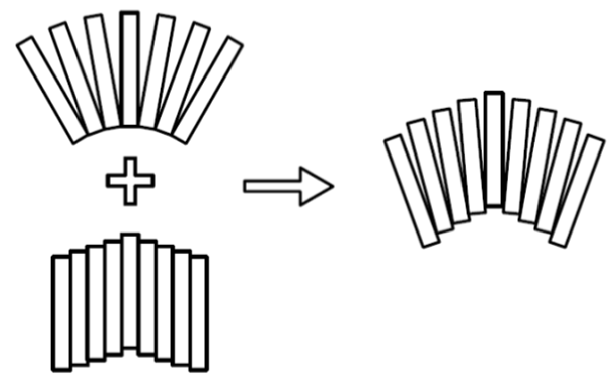
As shown in
Figure 5, relative rotation and relative dislocation will occur between adjacent segments. The longitudinal deformation of the shield tunnel is considered to be formed by combining shear dislocation and rigid body rotation between adjacent segments.
As shown in
Figure 6, the total relative displacement between adjacent ring segments numbered
m and
m + 1 is
δx, the relative horizontal displacement induced by the rigid rotation is
δx1, and the relative horizontal displacement caused by the dislocation is
δx2. Then, it satisfies the equation
δx =
δx1 +
δx2. Set
δx1 =
jxδx, where
jx is the proportionality coefficient for the rotation effects of the segment rings. When
jx = 0, there is no relative rotation between adjacent segments. It is consistent with the deformation model of dislocation proposed by Zhou et al. [
21]. When
jx = 1, the horizontal displacement is completely caused by the rotation of adjacent segments, which is the deformation mode of complete rotation.
Assuming that the adjacent shield tunnel meets the condition of deformation coordination with the surrounding soil, the deformation of the shield tunnel is the same as the soil deformation at the corresponding position:
where
l is the calculated position of the tunnel axis, take the center of foundation pit excavation as the zero point, and it is positive along the
Y-axis;
u(
l) is the horizontal deformation of adjacent shield tunnel, and
ut(
l) is the horizontal displacement of the soil at the tunnel axis.
The difference between the tunnel horizontal displacement values of adjacent segments is the relative horizontal displacement, which is:
where the serial numbers of the adjacent segment rings are
m and
m + 1, respectively, and
Dt is the width of the segment ring.
It can be assumed that sin (
θx) =
θ and cos (
θx) = 1 when the rotation angle
θx between the segment ring is small. Therefore, the calculation equation for the horizontal displacement caused by the rotation of the rigid body between the lining rings is:
Substituting
δx1 =
jxδx into Equation (13):
The shear force between the segment rings can be obtained as follows:
The maximum tension between rings is:
The strata resistance is:
In Equations (15) and (16):
ksl and
kt are the inter-ring shear stiffness and inter-ring tensile stiffness of the tunnel, which can be calculated by Guo et al. [
22]. In Equation (17), Vesic’s formula [
23] is used to calculate
k, which is the foundation reaction coefficient.
, where
μ is the soil Poisson’s ratio,
Es is the compressive modulus of the foundation soil, and (
EI)
eq is the equivalent bending stiffness of the shield tunnel, which was calculated by Ye et al. [
24].
2.3.2. The Potential Energy in the Process of the Shield Tunnel Deformation
The potential energy in the deformation process of the shield tunnel contains the following four parts:
- (1)
Work done by extra horizontal load due to the excavation of foundation pit:
where:
. 2
N is the number of shield tunnel segments within the calculation range, which is related to the range affected by the shield tunnel because of the excavation of the foundation pit. Theoretically, the greater the value of
n is, the higher the calculation accuracy will be. However, the corresponding calculation amount will also increase, and the calculation efficiency will be affected.
- (2)
Work done by overcoming the soil layer resistance:
- (3)
Work done by overcoming the shear forces between rings:
- (4)
Work done by overcoming the tension caused by rotation between rings:
where:
.
Therefore, it can be acquired that:
The potential energy caused by the deformation of the shield tunnel:
2.3.3. Fourier Expansion of Curve Function of Shield Tunnel’s Horizontal Displacement
In this paper, the distribution of the excavation area in the simplified model is parallel to the adjacent shield tunnel. Theoretically, the horizontal displacement of the tunnel should be symmetrical at about the middle point of the foundation pit excavation. Therefore, Fourier series expansion can be performed according to the cosine function to obtain:
where:
;
;
n is the Fourier expansion series.
2.3.4. Solve the Variational Governing Equation
Based on the principle of the least potential energy, the potential energy
Ep is taken as the extreme value for each undetermined coefficient:
where
ai is the
i-th element in matrix
A, i.e., the tunnel deformation curve function coefficient polynomial.
It can be obtained by solving the above Equations:
The above expressions can be abbreviated as matrix form:
Calculated by Equation (27), the undetermined coefficient matrix
AT can be obtained:
Substituting the undetermined coefficient matrix
AT back into Equation (24) can obtain the horizontal displacement distribution function of the shield tunnel:
Therefore, the amount of misalignment between adjacent shield segments is:
Then, the shear force
Qx between adjacent shield segments is:
3. Engineering Case Analysis
Since the longitudinal deformation of adjacent shield tunnels is mainly horizontal displacement because of the foundation pit excavation, this paper selects four examples of foundation pit engineering. In case history 1, this paper uses a polynomial function to fit the measured value of the enclosure structure deformation. It predicts the deformation of the enclosure structure in case 2, case 3, and case 4. Then, the horizontal displacement curve of the side shield tunnel axis is calculated to be compared with the measured curve to prove the reliability of this method.
3.1. Case History 1
There was a foundation pit adjacent to Shanghai Metro Line 1 [
1], the plane size of the excavation area was
L = 45 m,
B = 63 m, the length of the enclosure structure was
H = 23 m, and the excavation depth was 11.5 m. Metro Line 1 was located under the road beside the foundation pit. The buried depth of the tunnel axis was 10.1 m. The minimum distance between the tunnel axis and the enclosure structure of the foundation pit was s = 7 m. The shield tunnel segment ring outer diameter
D = 6.2 m, ring width
Dt = 1, lining thickness
t = 0.35 m, calculation parameters
ksl = 2.23 × 10
6 kN/m, and
kt = 9.39 × 10
5 kN/m. The excavation scope of the foundation pit is mainly silty clay, muddy silty clay, and muddy clay. The tunnel was mainly located in the silty clay layer, and the Poisson’s ratio of the soil was
μ = 0.35.
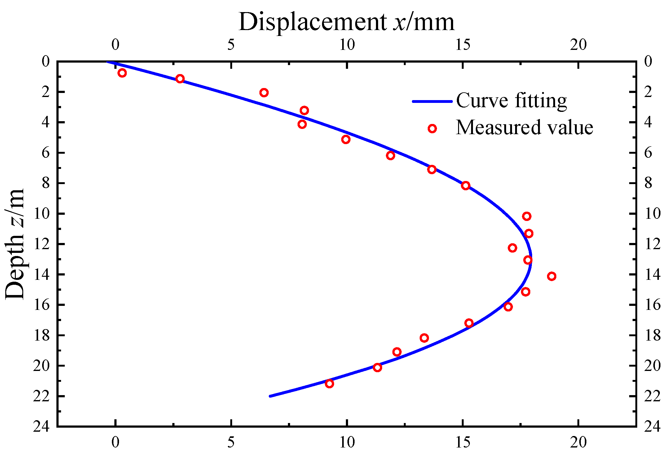
The comparison between the fitting curve and the measured curve of the deformation of the enclosure structure is shown in
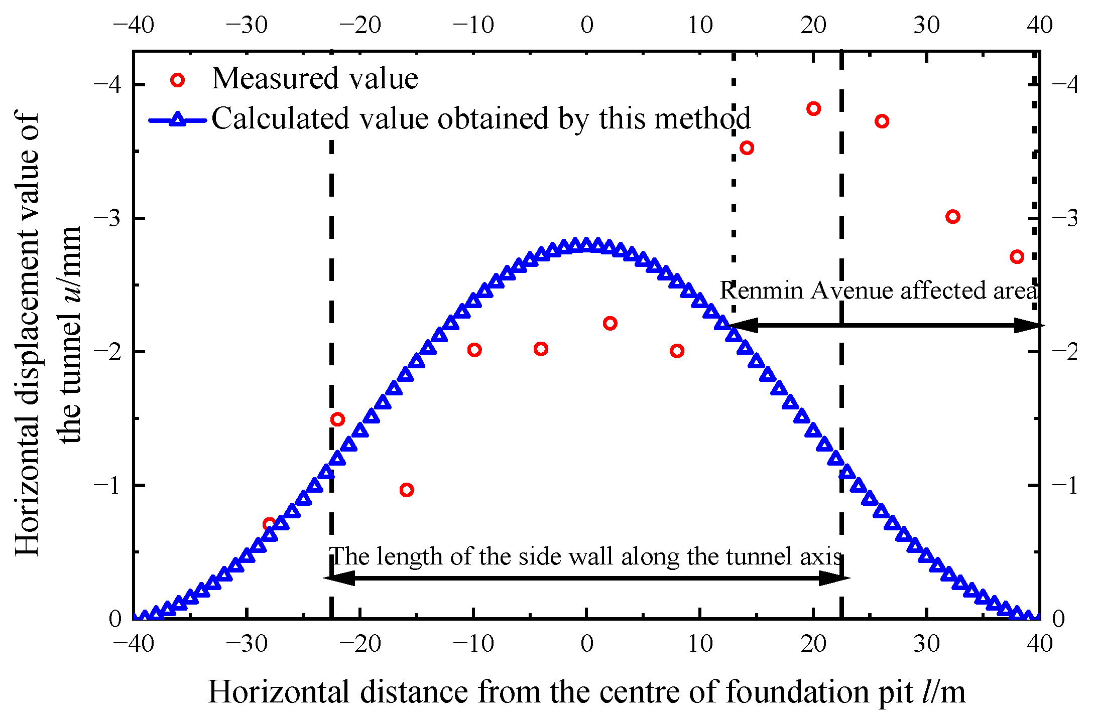
Figure 7. It can be seen that the fitted curve is in good agreement with the measured value of the foundation pit enclosure deformation. The fitting function is:
. Substituting the deformation of the enclosure structure obtained by the fitting function into the calculation, the comparison curve between the calculated value of the horizontal displacement and the measured data is shown in
Figure 8. Taking the measured deformation data of the engineering envelope as the calculation parameter, the calculation results by the method in this paper are consistent with the actual measurement results. The rotation effects proportionality coefficient of the shield tunnel is
jx = 0.2. The measuring point is perpendicular to People’s Avenue in the area of 14~38 m away from the excavation center. The tunnel’s horizontal displacement is further enlarged due to the vehicle load. The maximum horizontal displacement measured is 3.82 mm, while the value calculated is 2.79 mm. It can be found that the horizontal displacement of the shield tunnel presents a normal distribution. The horizontal displacement close to the excavation center is relatively large, and the two sides decrease successively.
3.2. Case History 2
There was a foundation pit adjacent to Hangzhou Metro Line 2 at Shixinzhong Road and Jincheng Road in Xiaoshan District. The plane excavation size of the foundation pit was
L = 68 m,
B = 72 m, with a 15.8-m excavation depth. The continuous underground wall penetrates 37.2 m below the ground. The minimum distance between the enclosure structure and the shield tunnel axis was
s = 12.6 m [
25]. The shield tunnel lining outer diameter was
D = 6.2 m, using C50 concrete segments, a thickness
t = 0.35 m, and ring width
Dt = 1.2 m. Sixteen M30 longitudinal bolts connect the segment rings, according to the calculations
ksl = 2.23 × 10
6 kN/m,
kt = 9.39 × 10
5 kN/m, and (
EI)
eq = 1.1 × 10
8 kN·m
2. The tunnel axis was buried 14.3 m deep and was located in a layer of silt mixed with silt and sandy silt. Miscellaneous fill, silty clay, sandy silt, and silty sand are mainly distributed within the excavation area of the foundation pit. According to the actual engineering geology, the Poisson’s ratio of soil
μ = 0.4,
Es = 6.39 MPa. In this foundation pit, the excavation process was divided into four layers of soil for layered excavation. The thickness of each layer from top to bottom was 1.6 m, 4.9 m, 4.8 m, and 4.5 m.
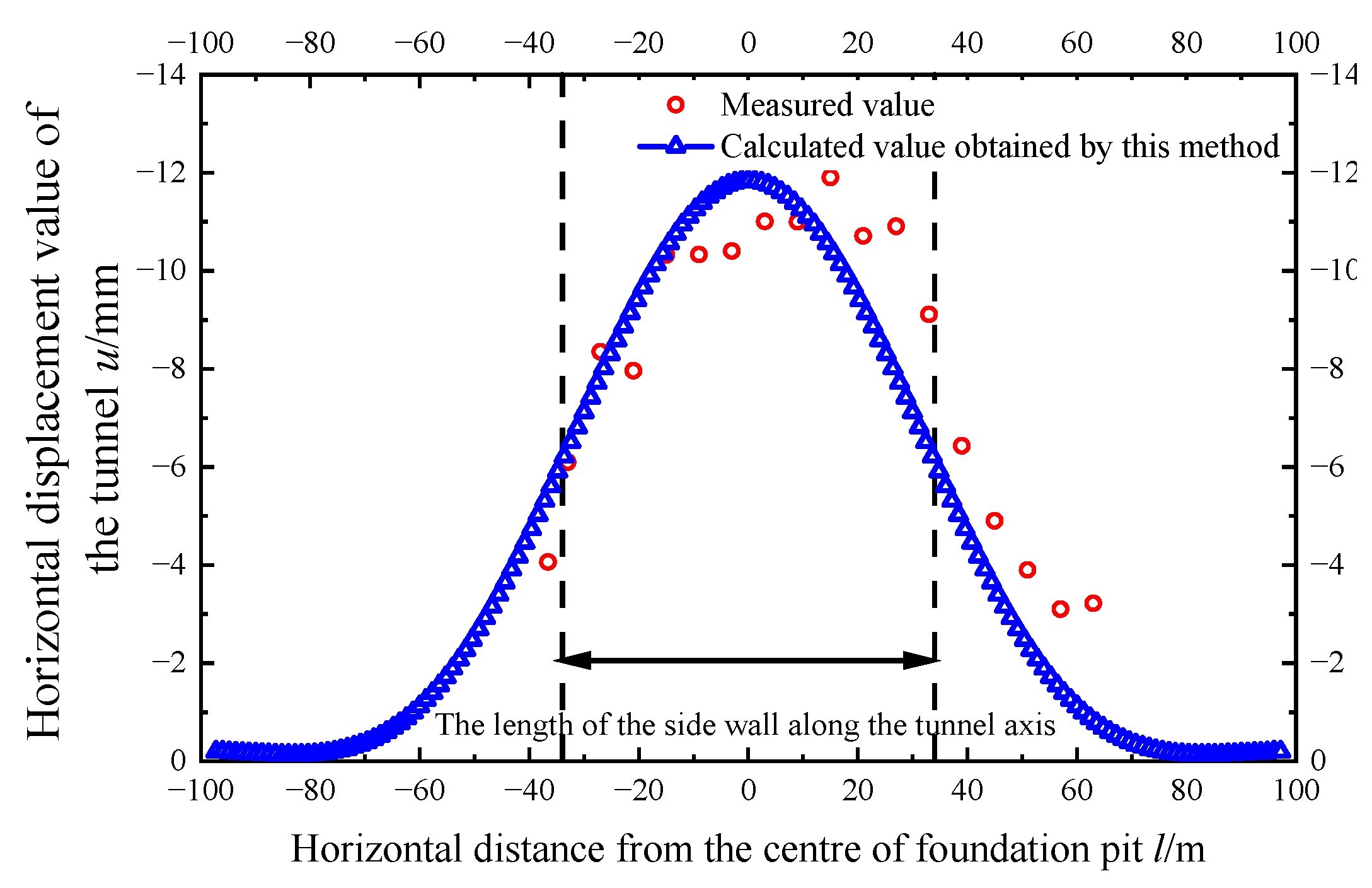
Figure 9 shows the comparison between the value calculated and the data measured of the horizontal displacement of the adjacent shield tunnel. As
Figure 9 shows, the calculated values are in reasonable agreement with measured data. The control parameter is
vmax/
d = 0.6% for the deformation of the enclosure structure in the calculation case. The rotation effect ratio coefficient of the adjacent shield tunnel
jx is 0.2. The horizontal displacement value of the adjacent shield tunnel is mainly negative in
Figure 8, which means that the displacement is along the negative direction of the
x-axis. The maximum horizontal displacement calculated is 11.46 mm, and the maximum value measured is 11.90 mm. The horizontal displacement presents a normal distribution. The horizontal displacement near the excavation center is relatively large, and it decreases successively on both sides. The length of the central uplift affected area of the tunnel is about twice the length of the enclosure structure along the tunnel axis.
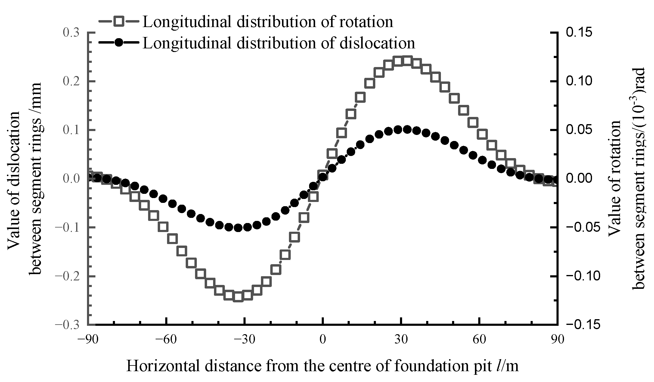
The values of the dislocation and rotation angles between the rings are essential to the security of the tunnel structure and waterproof system. The greater the rotation angle between the rings, the larger the opening of the ring seam. The probability of leakage in the shield tunnel will be significantly increased when the seam opening and dislocation values between the rings are large. Therefore, it is necessary to estimate the amount of seam opening and dislocation between the rings.
Figure 10 shows the calculated curve of the offset of the shield tunnel segments and rotation angle between the rings. It can be seen that the segment displacement and inter-ring rotation angle at the maximum horizontal displacement of the side tunnel corresponding to the excavation center of the foundation pit is close to 0, with almost no misalignment deformation and relative rotation deformation. The maximum misalignment amount of the segment is 0.24 mm, and the maximum ring-to-ring corner is 5 × 10
−5 rad. Refer to Zhang et al. [
26] for the classification of the safety assessment level of the misalignment and corners. The corresponding evaluation level of the misalignment and corners is Level IV. There is a more significant potential safety hazard. The maximum amount of misalignment and the maximum turning angle appear close to the two inflection points of the horizontal displacement curve of the shield tunnel, and the distance from the excavation center of the foundation pit is about 36 m.
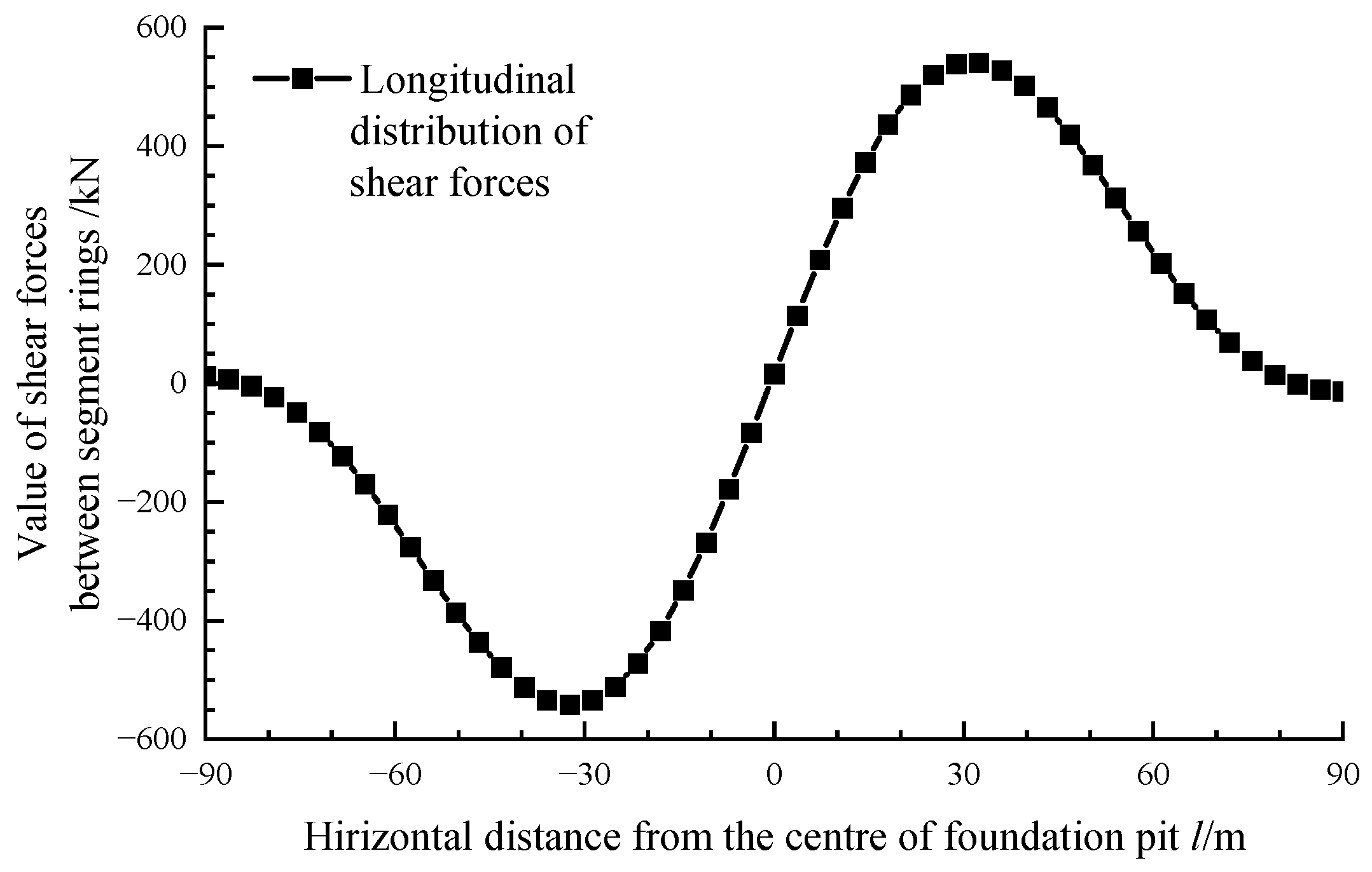
Figure 11 shows the shear force value calculated between the rings of the adjacent shield tunnel. As
Figure 10 shows, The variation rule of shear force value between rings of shield tunnel is the same as the variation rule of tunnel misalignment. The maximum shear force is 540.6 kN, which occurs at the position where the tunnel displacement is the largest. In this project, sixteen M30 bolts connect adjacent tunnel rings, and the shear strength limit is 626.22 kN. Although the calculated maximum shear force exceeds this limit, it is very close. Attention should be paid to strengthening tunnel monitoring.
3.3. Case History 3
The plane size of the excavation area of a certain foundation pit [
27] adjacent to Shanghai Metro Line 1 was
L = 70 m,
B = 42 m, and the excavation depth was
d = 10 m. Metro Line 1 was located under the road beside the foundation pit. The distance between the retaining structure and the shield tunnel axis was
s = 7.2 m. The outer diameter of the shield tunnel segment ring was
D = 6.2 m, the ring width
Dt = 1 m, the lining thickness
t = 0.35 m, and the calculation parameters
ksl = 2.23 × 10
6 kN/m and
kt = 9.39 × 10
5 kN/m. The depth of shield tunnel was 10.1 m and was located in a layer of sandy silt and silty clay. The excavation range of the foundation pit was mainly filled with soil, silty clay, and sandy silt. The Poisson’s ratio of the soil was
μ = 0.35,
Es = 7.35 MPa.
Figure 12 displays the comparison curve between the value calculated and data measured of the horizontal displacement of the shield tunnel. As the figure shows, the calculated results are in good agreement with the measured values. The rotation effect ratio coefficient of the shield tunnel beside the foundation pit is
jx = 0.2. In the calculation example, the control parameter is
vmax/
d = 0.25% of the deformation of enclosure structure. The maximum measured horizontal displacement is 3.66 mm, and the maximum horizontal displacement calculated is 3.68 mm. The curve of the horizontal displacement presents a normal distribution, and the horizontal displacement is relatively large near the center of the excavation. Furthermore, it is decreasing on both sides. Similar to case history 2, the length of the central uplift affected area on the shield tunnel is about twice the length of the sidewall of the foundation pit along the tunnel axis.
The length of the foundation pit is closed to that of case 2, while the excavation depth in case 3 is only about 60% of that in case 2, so the sidewall of the foundation pit is less deformed. The resulting soil deformation is relatively more minor, so the horizontal displacement of the adjacent shield tunnel in case history 3 is more diminutive compared with case history 2, but the horizontal displacement distribution law is similar to that of case history 2.
3.4. Case History 4
The size of the excavation area of a foundation pit [
28] in Eastern China was
L = 20 m,
B = 30 m, and the excavation depth was
d = 7 m. Metro Line 1 was located under the pavement beside the foundation pit. The distance between the retaining structure and the shield tunnel axis was
s = 7 m. The shield tunnel segment ring outer diameter was
D = 6 m, the lining thickness was
t = 0.45 m, and the calculation parameters were
ksl = 2.23 × 10
6 kN/m and
kt = 9.39 × 10
5 kN/m. The depth of the tunnel axis was 13 m, and the shield tunnel was in silty clay. The range of excavation mainly included filling and clay. The Poisson’s ratio of soil was
μ = 0.4 and
Es = 20 MPa. In this foundation pit, the excavation process was divided into two layers of soil for layered excavation, and the thickness of each layer of excavation from top to bottom was 2 m and 5 m, respectively.
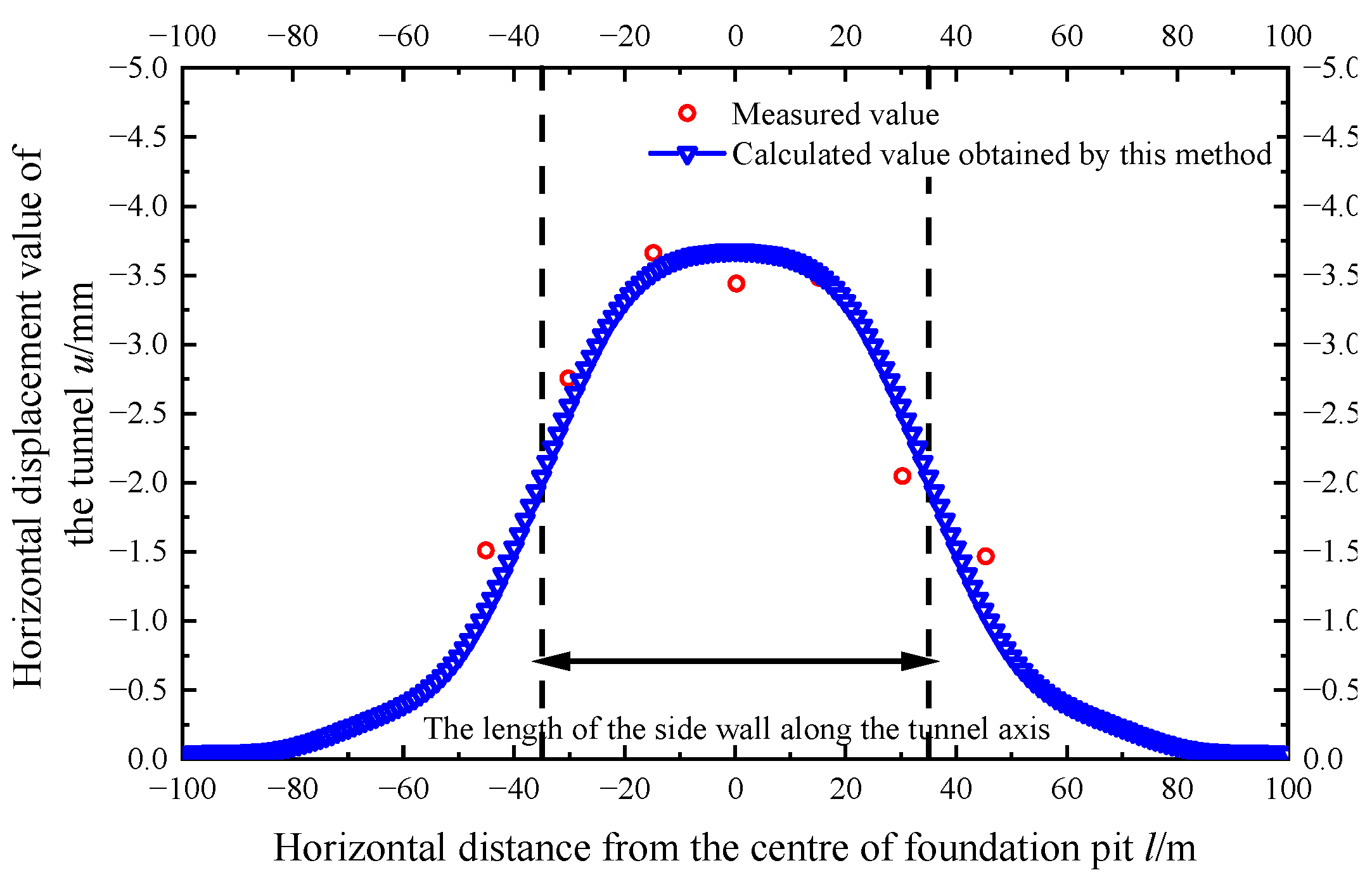
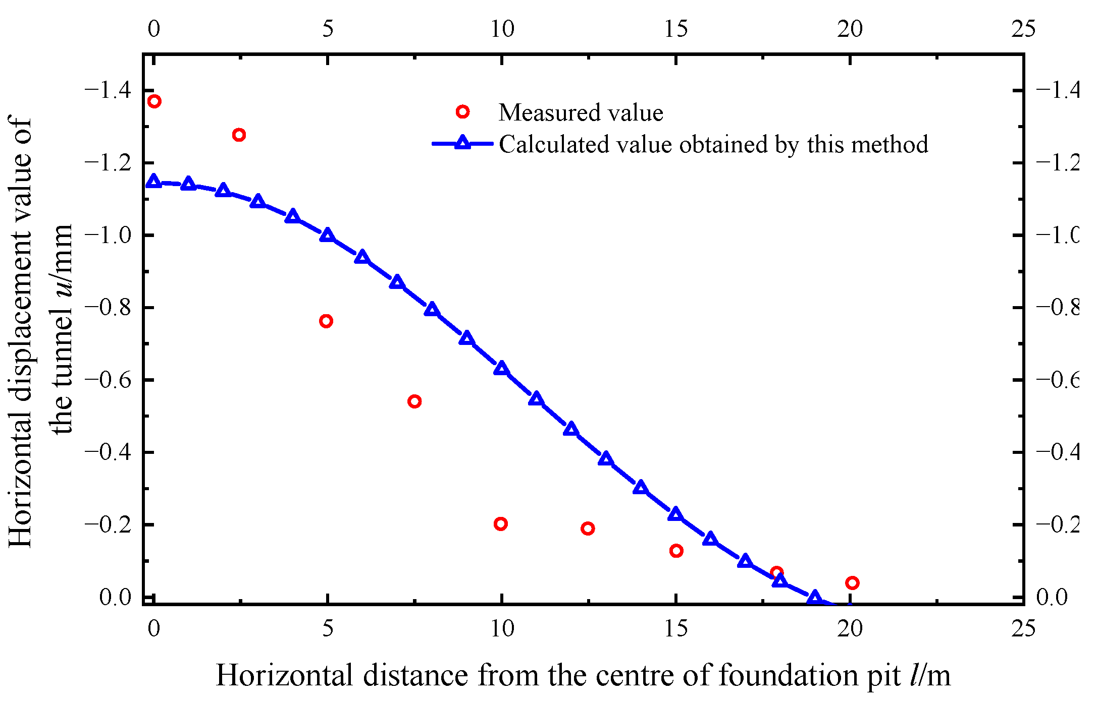
Figure 13 shows the comparison curve between the calculated value and measured data of the horizontal displacement. As shown in the figure, the curve calculated is in good agreement with the measured data. The rotation effect ratio coefficient
jx is 0.2 in case 4. In the calculation example, the control parameter is
vmax/
d = 0.8% of the deformation of the enclosure structure. As the figure shows, the maximum horizontal displacement measured is 1.34 mm, while the value calculated by the method in this paper is 1.15 mm.
3.5. Case History 5
There was an excavation in the vicinity of an existing tunnel of the Xinyi Line of the Taipei Metro [
29]. It was carried out to a depth of 15.9 m in six stages (2.3 m, 5.5 m, 8.4 m, 11.3 m, 13.7 m, and 15.9 m). The size of the excavation is L = 59 m, B = 30 m. The down-track tunnel is only 7.3 m away from the pit at the most critical location. The buried depth of the down track tunnel is 19.15 m. The shield tunnel segment ring outer diameter
D = 6 m and is lined with reinforced concreted segments of 250 mm in thickness. The site is located in the TK2 Zone of the Taipei Basin, and the subsoils comprise an alternation of silty clay and silty sand sublayers. The Poisson’s ratio of the soil was
μ = 0.3 and
Es = 12 MPa.
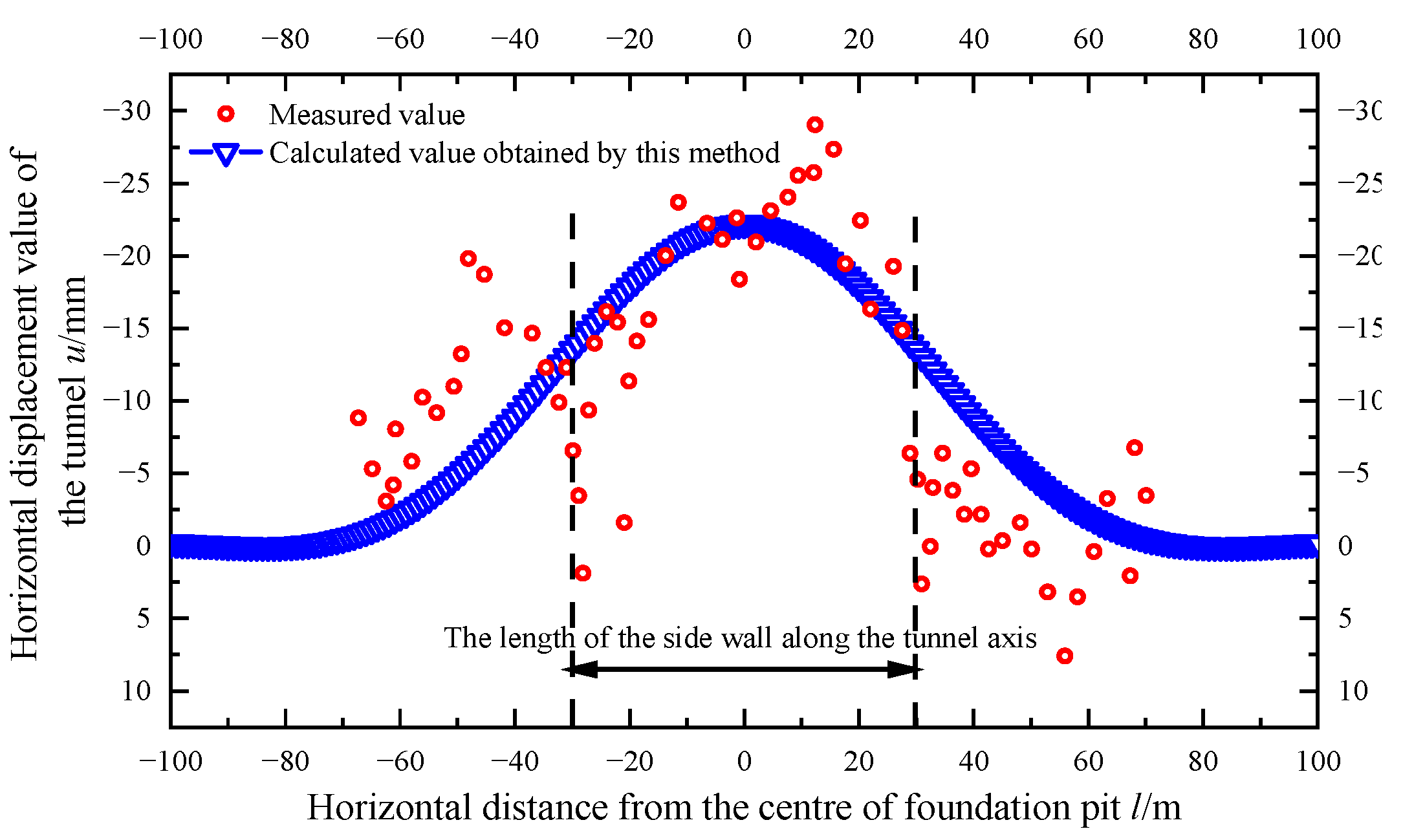
Figure 14 shows the comparison curve between the calculated value and measured data of the horizontal displacement. In the calculation example, the control parameter
vmax/
d = 0.9% of the deformation of the enclosure structure, and the rotation effect ratio coefficient
jx is 0.2. As the figure shows, the maximum horizontal displacement measured is 22.21 mm, while the value calculated by the method in this paper is 29 mm.
4. Analysis of Influencing Factors of Longitudinal Deformation of the Adjacent Tunnel
Taking the case history 3 of this article as the basic working condition, while other parameters remain unchanged, the effect of the deformation control parameters vmax/d, s, and h are analyzed in this section, respectively.
4.1. Deformation Control Parameters of Enclosure Structure vmax/d
The maximum deformation of enclosure structure is mainly controlled during the construction of the foundation pit. One of the main factors affecting the cumulative maximum deformation of the enclosure structure is the excavation depth of the foundation pit [
30,
31,
32]. The
vmax/
d of the underground diaphragm wall enclosure structure in the Hangzhou area collected by Wang [
31] varied from 0.09% to 0.61%. Xu et al. [
32] analyzed the actual measurement data of the enclosure structure of the underground diaphragm wall in the Shanghai area. The deformation of the enclosure structure in the Shanghai area is very close to the deformation of the Chinese Taipei area collected by Ou et al. [
30],
vmax/
d is between 0.1% and 1.0%, with an average value of 0.42%.
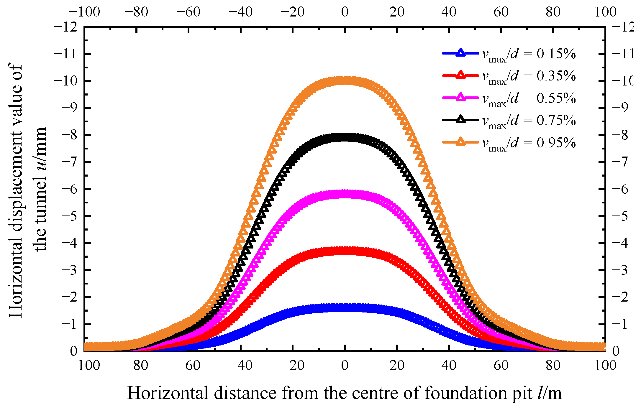
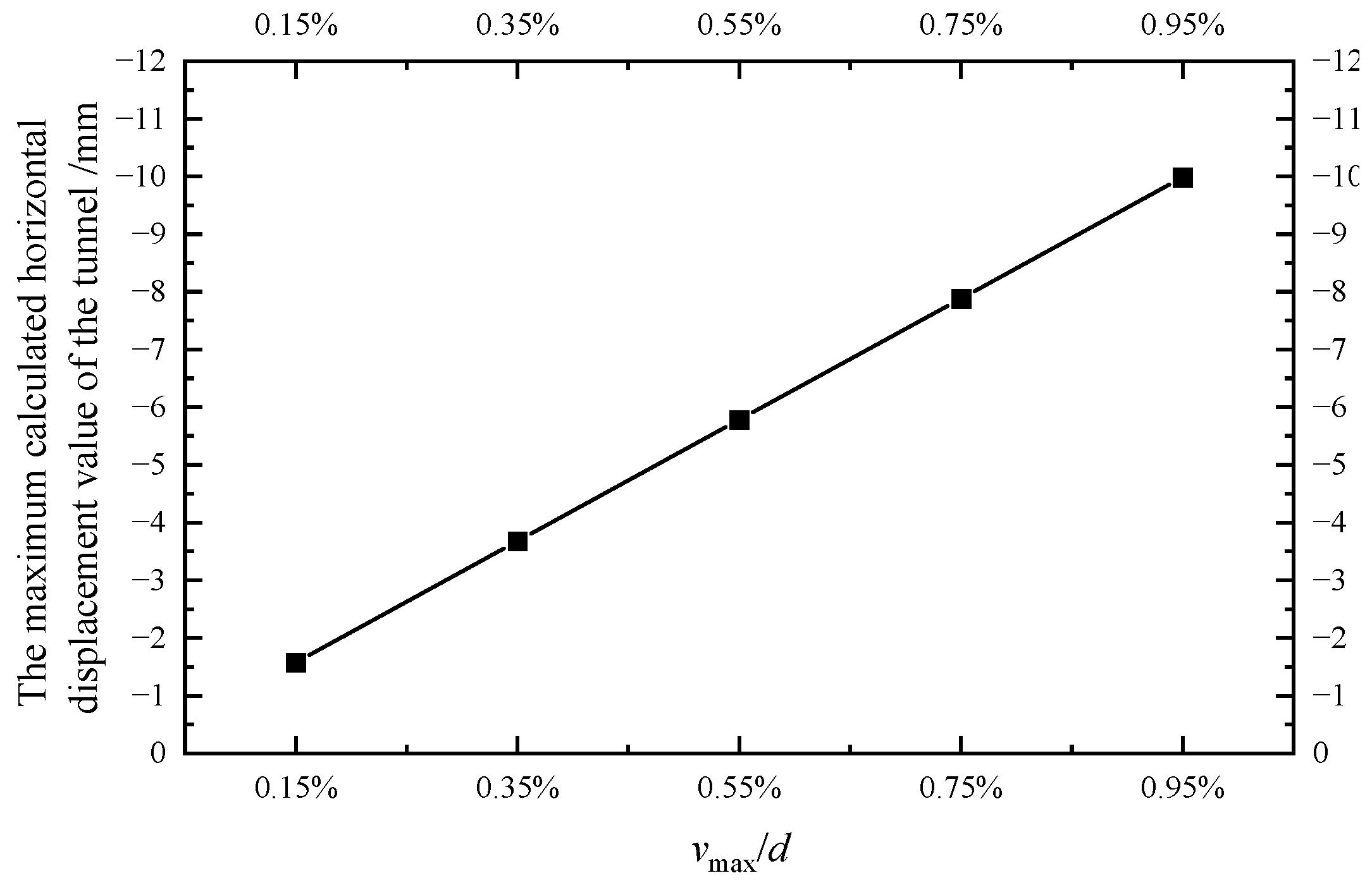
Figure 15 shows the distribution curves of the horizontal displacement calculated when
vmax/d is 0.15%, 0.35%, 0.55%, 0.75%, and 0.95%, respectively. As shown in
Figure 15, when the deformation control parameter
vmax/
d = 0.15%, the horizontal displacement is the smallest, which is only 1.58 mm. As the deformation control parameter
vmax/
d increases, the horizontal displacement value and range of the adjacent shield tunnel also increase. As shown in
Figure 16,
vmax/
d has a linear relationship with the maximum horizontal displacement value of the side tunnel. As the deformation control parameter
vmax/
d increases, the maximum horizontal displacement value of the adjacent tunnel increases linearly.
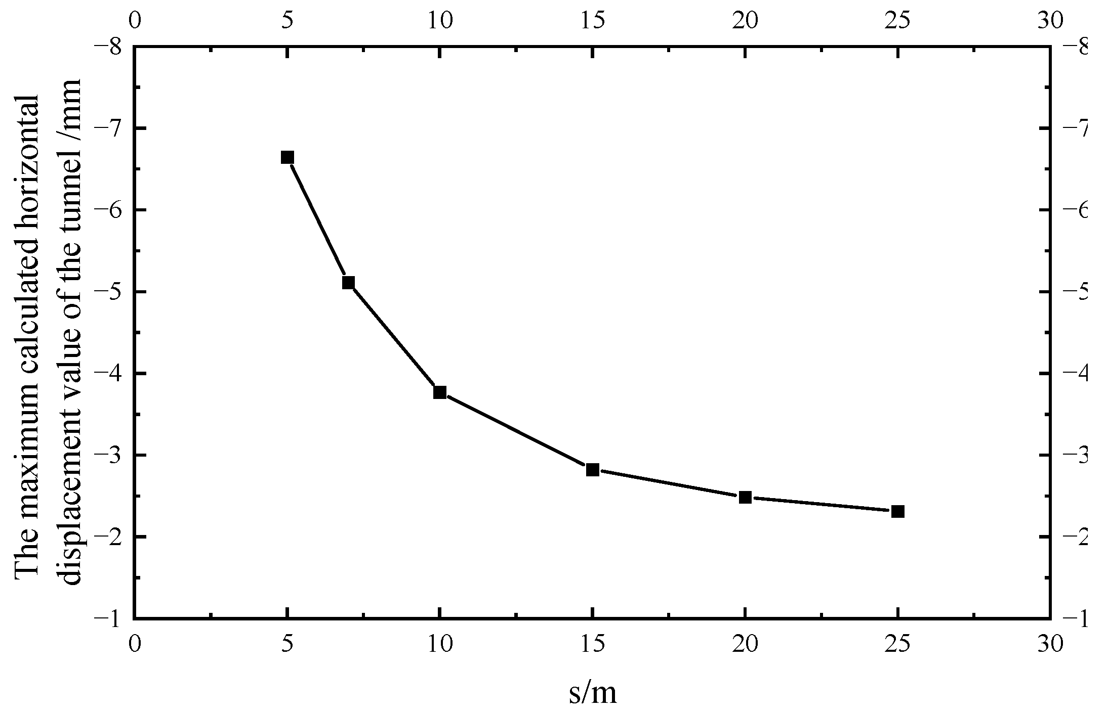
4.2. Distance between the Enclosure Structure and Adjacent Shield Tunnel Axis s
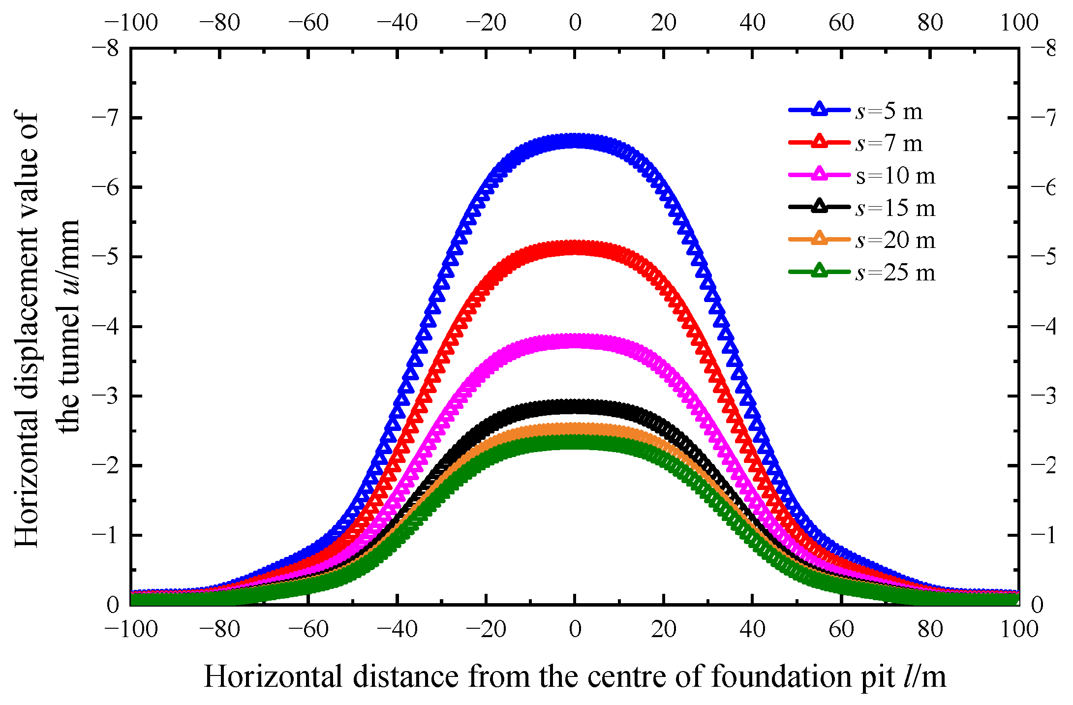
Figure 17 shows the horizontal displacement distribution curve of the adjacent shield tunnel calculated when the distances between the enclosure structure and adjacent shield tunnel axis are 5 m, 7 m, 10 m, 15 m, 20 m, and 25 m, respectively. As shown in
Figure 17, as the distance between the enclosure structure and the axis of adjacent shield tunnel increases, the maximum horizontal displacement of the side shield tunnel decreases, and the decrease rate also becomes smaller. When
s = 25 m, which is 2.5 times the excavation depth of the foundation pit, the maximum horizontal displacement becomes stable.
Figure 18 shows the maximum horizontal displacement curve of the adjacent shield tunnel at different
s. As shown in the figure, as the distance between the enclosure structure and the axis of the adjacent shield tunnel increases, the maximum horizontal displacement of the side tunnel shows a nonlinear decreasing rule. Zhang et al. [
4] also obtained similar conclusions when they studied the impact of the distance between the excavation center of foundation pit and the axis of the tunnel.
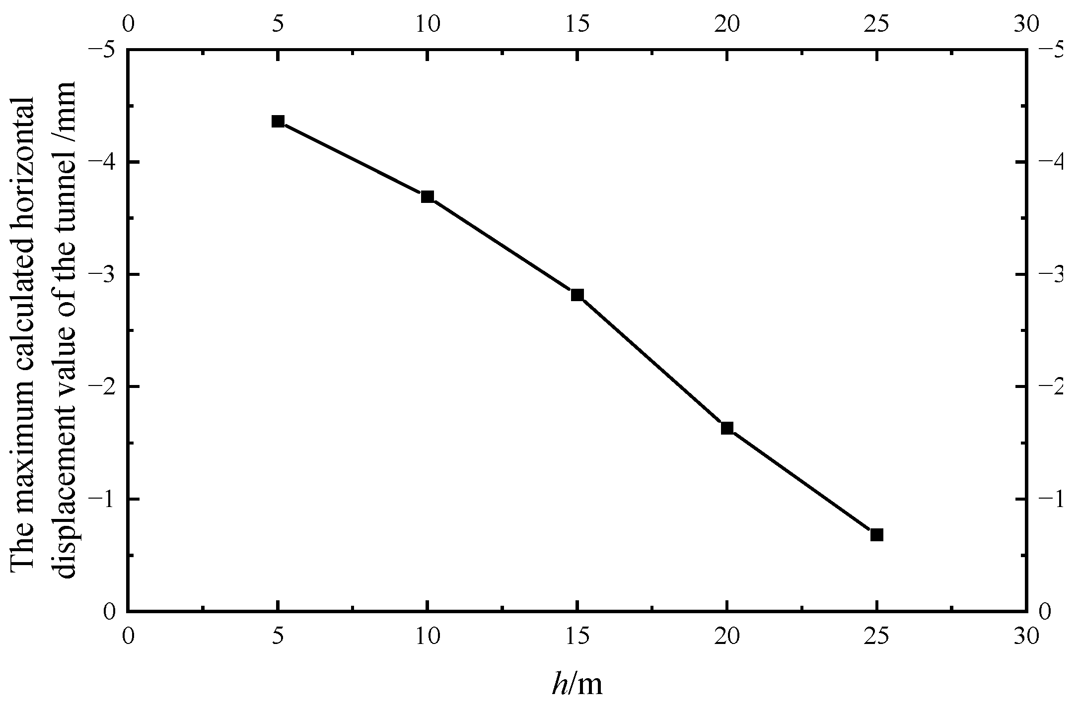
4.3. Buried Depth of Adjacent Shield Tunnel Axis h
Figure 19 shows the distribution curve of the calculated horizontal displacement of the adjacent shield tunnel when the depth
h of the tunnel axis is taken as 5 m, 10 m, 15 m, 20 m, and 25 m. As the figure shows, the excavation significantly impacts the adjacent shield tunnel with the shallow buried depth in
Figure 19. The horizontal displacement of the adjacent shield tunnel decreases with the increase of buried depth of tunnel, and the influence range of longitudinal deformation also decreases. As shown in
Figure 20, with the increase of the buried depth
h, the maximum of horizontal displacement presents a nonlinear decreasing law. Zhang et al. [
4] and Ying et al. [
33] also got similar results.
5. Conclusions
This paper establishes a foundation pit sidewall deformation prediction model that takes the ratio of the cumulative maximum deformation of the enclosure structure to the excavation depth vmax/d as the control parameter. The soil displacement caused by sidewall deformation is calculated based on the virtual image technique. Meanwhile, the collaborative deformation model considering the rotating and dislocation of the shield tunnel is used to establish a calculation method of the horizontal displacement of a shield tunnel adjacent to a foundation pit. Additionally, the case verification and influencing factor analysis were carried out, and the following conclusions have been obtained.
- (1)
The method of calculation in this paper has the advantage of making full use of onsite monitoring data, solving the problem that the size of sidewall unloading could not be verified in the past, and the calculation is relatively simple. The calculated values are in good agreement with the measured data, and the curve of horizontal displacement of the shield tunnel beside a foundation pit shows a normal distribution. The method of calculation in this paper can be used to evaluate the safety status of adjacent tunnels before excavation of the foundation pit.
- (2)
The horizontal displacement of the adjacent shield tunnel near the center of the excavation of the foundation pit is relatively large, but the amount of dislocation between the segments and the relative rotation angle is slight; the maximum inter-ring rotation angle, the maximum dislocation amount, and shear force value between the segments all appear near the two inflection points of the horizontal displacement curve of the adjacent shield tunnel.
- (3)
As the deformation of the enclosure structure, the effect value, and the scope of the longitudinal deformation of the side shield tunnel also increase, the longitudinal deformation of the side shield tunnel decreases nonlinearly with the distance between the axis of the shield tunnel and the enclosure structure increases; the excavation of the foundation pit has a more significant influence on an adjacent shield tunnel with a shallower buried depth. The influence diminishes gradually as the buried depth of the side shield tunnel increases.
In this paper, several simplifications have been made in the analysis process. For example, the influence of tunnels, precipitation, layering of the foundation soil, the nonlinear effect of the tunnels and soil is not considered, and the nonuniformity of soil convergence is also neglected. The theoretical results may contain certain errors that can be studied further.
Author Contributions
Conceptualization, Z.W. and B.G.; methodology, G.W.; software, B.G.; validation, D.Y., B.G. and G.W.; formal analysis, D.Y.; investigation, C.H.; data curation, Z.W.; writing—original draft preparation, D.Y.; writing—review and editing, B.G.; visualization, Z.W.; supervision, B.G.; project administration, D.Y.; and funding acquisition, Z.W. and G.W. All authors have read and agreed to the published version of the manuscript.
Funding
This research was funded by the Basic Public Welfare Research Projects in Zhejiang Province (LGF22E080012), the General Scientific Research Projects for Agriculture and Social Development in Hangzhou (grant number 20201203B127), and the Joint Fund of Zhejiang Natural Science Foundation Committee and Power China Huadong Engineering Corporation (grant number LHZ19E090001).
Institutional Review Board Statement
Not applicable.
Informed Consent Statement
Not applicable.
Data Availability Statement
Not applicable.
Acknowledgments
We would like to thank Jiuchun Sun for the support in obtaining the engineering cases.
Conflicts of Interest
The authors declare no conflict of interest.
References
- Jia, J. Deflection controlling measures and practices of deep foundation pits by use of top-down excavation method. Chin. J. Geotech. Eng. 2007, 29, 304–308. [Google Scholar]
- Xu, C.J.; Sun, F.M.; Chen, J.Y.; Xu, L.G. Analysis on the deformation and stress control measures of metro tunnel near a foundation pit. J. Civ. Archit. Environ. Eng. 2013, 35, 75–80. [Google Scholar] [CrossRef]
- Chang, C.T.; Sun, C.W.; Duann, S.W.; Hwang, R.W. Response of a Taipei Rapid Transit System (TRTS) tunnel to adjacent excavation. Tunn. Undergr. Space Technol. 2001, 16, 151–158. [Google Scholar] [CrossRef]
- Zhang, Z.G.; Huang, M.S.; Wang, W.D. Evaluation of deformation response for adjacent tunnels due to soil unloading in excavation engineering. Tunn. Undergr. Space Technol. 2013, 38, 244–253. [Google Scholar] [CrossRef]
- Zhou, Z.L.; Chen, S.G.; Tu, P.; Zhang, H.S. An analytic study on the deflection of subway tunnel due to adjacent excavation of foundation pit. J. Mod. Transp. 2015, 23, 287–297. [Google Scholar] [CrossRef]
- Liang, R.Z.; Xia, T.D.; Huang, M.S.; Lin, C.G. Simplified analytical method for evaluating the effects of adjacent excavation on shield tunnel considering the shearing effect. Comput. Geotech. 2017, 81, 167–187. [Google Scholar] [CrossRef]
- Zheng, G.; Du, Y.; Cheng, X.; Diao, Y.; Deng, X.; Wang, F. Characteristics and prediction methods for tunnel deformations induced by excavations. Geomech. Eng. 2017, 12, 361–397. [Google Scholar] [CrossRef]
- Shi, J.W.; Ng, C.W.W.; Chen, Y.H. Three-dimensional numerical parametric study of the influence of basement excavation on existing tunnel. Comput. Geotech. 2015, 63, 146–158. [Google Scholar] [CrossRef]
- Ng, C.W.W.; Shi, J.W.; Mašín, D.; Sun, H.S.; Lei, G.H. Influence of sand density and retaining wall stiffness on three-dimensional responses of tunnel to basement excavation. Can. Geotech. J. 2015, 52, 1811–1829. [Google Scholar] [CrossRef]
- Wang, L.F.; Pang, J.; Xu, Y.F.; Yang, K.F. Influence of foundation pit excavation on adjacent metro tunnels. Rock Soil Mech. 2016, 37, 2004–2010. [Google Scholar] [CrossRef]
- Simpson, B.; Vardanega, P.J. Results of monitoring at the British Library excavation. Proc. Inst. Civ. Eng.-Geotech. Eng. 2014, 167, 99–116. [Google Scholar] [CrossRef] [Green Version]
- Wei, G.; Zhao, C.L. Calculation method of additional load of adjacent metro tunnels due to foundation pit excavation. Chin. J. Rock Mech. Eng. 2016, 35, 3408–3417. [Google Scholar] [CrossRef]
- Zhang, X.H.; Wei, G.; Jiang, C.W. The study for longitudinal deformation of adjacent shield tunnel due to foundation pit excavation with consideration of the retaining structure deformation. Symmetry 2020, 12, 2103. [Google Scholar] [CrossRef]
- Sagaseta, C. Analysis of undrained soil deformation due to ground loss. Geotechnique 1987, 37, 301–320. [Google Scholar] [CrossRef]
- Verruijt, A.; Booker, J.R. Surface settlement due to deformation of a tunnel in an elastic half plane. Geotechnique 1996, 46, 753–756. [Google Scholar] [CrossRef]
- Xu, K.J.; Harry, G.P. Theoretical study of pile behaviour induced by a soil cut. Presented at the ISRM International Symposium, Melbourne, Australia, 19–24 November 2000. [Google Scholar]
- Zhang, A.J.; Mo, H.H.; Li, A.G.; Gao, W.; Xiang, W. Two-stage analysis method for behavior of adjacent piles due to foundation pit excavation. Chin. J. Rock Mech. Eng. 2013, 32, 2746–2750. [Google Scholar]
- Zhang, Z.G.; Zhao, Q.H.; Xu, C.; Hu, L.S. Simplified analysis of adjacent single-pile response subjected to foundation pit excavation based on virtual image technique. Rock Soil Mech. 2016, 37, 2011–2020. [Google Scholar] [CrossRef]
- Liu, M.L.; Fang, Q.; Zhang, D.L.; Hou, Y.J. Prediction of transient deformation due to excavation based on improved MSD method. Chin. J. Rock Mech. Eng. 2018, 37, 1700–1707. [Google Scholar] [CrossRef]
- Zhang, X.H.; Wei, G.; Lin, X.B.; Xia, C.; Wei, X.J. Transverse force analysis of adjacent shield tunnel caused by foundation pit excavation considering deformation of retaining structures. Symmetry 2021, 13, 1478. [Google Scholar] [CrossRef]
- Zhou, S.H.; He, C.; Xiao, J.H. Energy method for calculating deformation of adjacent shield tunnels due to foundation pit excavation considering step between rings. China Railw. Sci. 2016, 37, 53–60. [Google Scholar]
- Guo, L.; Yang, X.A.; Qiu, Y. Longitudinal heterogeneous equivalent continuous model for stagger joint segmental lining. Urban Mass Transit 2017, 20, 17–22. [Google Scholar] [CrossRef]
- Vesic, B.A. Bending of beams resting on isotropic elastic solids. J. Eng. Mech. 1961, 87, 35–53. [Google Scholar] [CrossRef]
- Ye, F.; He, C.; Zhu, H.H.; Sun, H.D. Longitudinal equivalent rigidity analysis of shield tunnel considering transverse characteristics. Chin. J. Geotech. Eng. 2011, 33, 1870–1876. [Google Scholar]
- Wei, G.; Li, J.; Xuan, H.L.; Dong, L.Z.; Xu, Y.Y.; Zhang, S.M. Monitoring data analysis on the influence of large deep foundation pit excavation on nearly metro shield tunnel. J. Railw. Sci. Eng. 2018, 15, 718–726. [Google Scholar] [CrossRef]
- Zhang, Z.G.; Cheng, Z.X.; Zhang, M.X.; Ma, S.K.; Lv, X.L. Dislocation Deformation for Existing Tunnel Longitudinal Structure Induced by Shield Tunneling by Under-crossing Type Considering Influence of Lining Permeability. China J. Highw. Transp. 2021; accepted. Available online: https://kns.cnki.net/kcms/detail/61.1313.U.20211105.1018.006.html(accessed on 5 November 2021).
- Shao, H.; Wang, R. Monitoring data analysis on influence of operating metro tunnel by nearly excavation construction. Chin. J. Undergr. Space Eng. 2011, 7, 1403–1408. [Google Scholar]
- Jiang, Z.H.; Zhang, Y.X. Calculation of influence on longitudinal deformation of adjacent tunnels due to excavation. J. Civ. Archit. Environ. Eng. 2013, 35, 7–11+39. [Google Scholar]
- Hwang, R.N.; Chen, B.S.; Wu, T.E.; Duann, S.W. Damage to a Metro Tunnel Due to Adjacent Excavation. In Forensic Geotechnical Engineering; Springer: New Delhi, India, 2016; pp. 369–377. [Google Scholar]
- Ou, C.Y.; Hsieh, P.G.; Chiou, D.C. Characteristics of ground surface settlement during excavation. Can. Geotech. J. 1993, 30, 758–767. [Google Scholar] [CrossRef]
- Wang, Z.D. Research on Deformation Behavior of Deep Excavation with Bracing Diaphragm Wall in Hangzhou Area. Master’s Thesis, Zhejiang University, Hangzhou, China, 2017. [Google Scholar]
- Xu, Z.H.; Wang, J.H.; Wang, W.D. Deformation behavior of diaphragm walls in deep excavations in Shanghai. China Civ. Eng. J. 2008, 41, 81–86. [Google Scholar] [CrossRef]
- Ying, H.W.; Cheng, K.; Yu, J.L.; Xu, R.Q.; Qiu, Z.J.; Zhang, X.B.; Qin, J.S.; Lou, C.H. Prediction of shield tunnel displacement due to adjacent basement excavation considering continuous deformation of ground. J. Zhejiang Univ. 2021, 55, 318–328. [Google Scholar] [CrossRef]
Figure 1.
Calculation model of the influence of foundation pit excavation on the tunnel. (a) Vertical view. (b) Front view.
Figure 1.
Calculation model of the influence of foundation pit excavation on the tunnel. (a) Vertical view. (b) Front view.
Figure 2.
Deformation diagram of the sidewall retaining structure.
Figure 2.
Deformation diagram of the sidewall retaining structure.
Figure 3.
Analysis flow chart of the virtual image technique.
Figure 3.
Analysis flow chart of the virtual image technique.
Figure 4.
Calculation model of the virtual image technique.
Figure 4.
Calculation model of the virtual image technique.
Figure 5.
The schematic diagram for the collaborative deformation mode of a shield tunnel [
13].
Figure 5.
The schematic diagram for the collaborative deformation mode of a shield tunnel [
13].
Figure 6.
Calculation model for the collaborative deformation of rotation and dislocation between shield tunnel segment rings [
13].
Figure 6.
Calculation model for the collaborative deformation of rotation and dislocation between shield tunnel segment rings [
13].
Figure 7.
Comparison of the actual measurement and fitting curve of the envelope structure deformation.
Figure 7.
Comparison of the actual measurement and fitting curve of the envelope structure deformation.
Figure 8.
Comparison of the calculated and measured values of the horizontal displacement of the tunnel beside the foundation pit in case 1.
Figure 8.
Comparison of the calculated and measured values of the horizontal displacement of the tunnel beside the foundation pit in case 1.
Figure 9.
Comparison of the calculated and measured values of the horizontal displacement of the tunnel beside the foundation pit in case 2.
Figure 9.
Comparison of the calculated and measured values of the horizontal displacement of the tunnel beside the foundation pit in case 2.
Figure 10.
Longitudinal distribution of the amount of dislocation between the rings and the corners between the shield tunnels in case 2.
Figure 10.
Longitudinal distribution of the amount of dislocation between the rings and the corners between the shield tunnels in case 2.
Figure 11.
Longitudinal distribution of shear force between the shield tunnel rings in case 2.
Figure 11.
Longitudinal distribution of shear force between the shield tunnel rings in case 2.
Figure 12.
Comparison of the calculated and measured values of the horizontal displacement of the tunnel beside the foundation pit in case 3.
Figure 12.
Comparison of the calculated and measured values of the horizontal displacement of the tunnel beside the foundation pit in case 3.
Figure 13.
Comparison of the calculated and measured values of the horizontal displacement of the tunnel beside the foundation pit in case 4.
Figure 13.
Comparison of the calculated and measured values of the horizontal displacement of the tunnel beside the foundation pit in case 4.
Figure 14.
Comparison of the calculated and measured values of the horizontal displacement of the tunnel beside the foundation pit in case 5.
Figure 14.
Comparison of the calculated and measured values of the horizontal displacement of the tunnel beside the foundation pit in case 5.
Figure 15.
The longitudinal distribution curve of the adjacent tunnel’s horizontal displacement when vmax/d uses different values.
Figure 15.
The longitudinal distribution curve of the adjacent tunnel’s horizontal displacement when vmax/d uses different values.
Figure 16.
The variation curve of the maximum calculated value of the shield tunnel’s horizontal displacement with different values of vmax/d.
Figure 16.
The variation curve of the maximum calculated value of the shield tunnel’s horizontal displacement with different values of vmax/d.
Figure 17.
The longitudinal distribution curve of the horizontal displacement of the shield tunnel by the side of the foundation pit under different s conditions.
Figure 17.
The longitudinal distribution curve of the horizontal displacement of the shield tunnel by the side of the foundation pit under different s conditions.
Figure 18.
The calculated curve of the maximum horizontal displacement of the shield tunnel by the side of the foundation pit changing with s.
Figure 18.
The calculated curve of the maximum horizontal displacement of the shield tunnel by the side of the foundation pit changing with s.
Figure 19.
The longitudinal distribution curve of the horizontal displacement of the shield tunnel by the side of the foundation pit under different h conditions.
Figure 19.
The longitudinal distribution curve of the horizontal displacement of the shield tunnel by the side of the foundation pit under different h conditions.
Figure 20.
The calculated curve of the maximum horizontal displacement of the shield tunnel by the side of the foundation pit changing with h.
Figure 20.
The calculated curve of the maximum horizontal displacement of the shield tunnel by the side of the foundation pit changing with h.
| Publisher’s Note: MDPI stays neutral with regard to jurisdictional claims in published maps and institutional affiliations. |
© 2022 by the authors. Licensee MDPI, Basel, Switzerland. This article is an open access article distributed under the terms and conditions of the Creative Commons Attribution (CC BY) license (https://creativecommons.org/licenses/by/4.0/).


