Article

Integrated Design of Moon-to-Earth Transfer Trajectory Considering Re-Entry Constraints

1
School of Aerospace Engineering, Beijing Institute of Technology, Beijing 100081, China
2
Key Laboratory of Autonomous Navigation and Control for Deep Space Exploration, Ministry of Industry and Information Technology, Beijing 100081, China
3
China Astronaut Research and Training Center, Beijing 100094, China
*
Author to whom correspondence should be addressed.
Appl. Sci. 2022, 12(17), 8716; https://doi.org/10.3390/app12178716
Submission received: 5 August 2022 / Revised: 25 August 2022 / Accepted: 27 August 2022 / Published: 30 August 2022
(This article belongs to the Special Issue Astrodynamics and Celestial Mechanics)

Abstract

:
The exploration of the Moon has always been a hot topic. The determination of the Moon-to-Earth transfer opportunity and the design of the precise transfer trajectory play important roles in manned Moon exploration missions. It is still a difficult problem to determine the Moon-to-Earth return opportunity for accurate atmospheric re-entry and landing, through which the actual return trajectory can be easily obtained later. This paper proposes an efficient integrated design method for Moon-to-Earth window searching and precise trajectory optimization considering the constraints of Earth re-entry and landing. First, an analytical geometry-based method is proposed to determine the state of the re-entry point according to the landing field and re-entry constraints to ensure accurate landing. Next, the transfer window is determined with the perilune heights, which are acquired by inversely integrating the re-entry state under the simplified dynamics as criterion. Then, the precise Moon-to-Earth trajectory is quickly obtained by a three-impulse correction. Simulations show the accuracy and efficiency of the proposed method compared with methods such as the patched-conic method and provide an explicit reference for future Moon exploration missions.

1. Introduction

As the only natural satellite of the Earth, the Moon is an important object for studying the formation and evolution of the Earth. Exploring the Moon not only can help human beings to further understand cosmic phenomena but can also promote the rapid development of human scientific and technological progress and applications [1,2]. Human exploration of the Moon began in the 1950s [3] as an important part of deep space exploration [4,5,6,7,8,9,10,11,12]. The second round of the lunar exploration climax was revived in the 1990s after a quiet period. The ESA, China, Japan, and India have carried out lunar exploration activities one after another since then [13,14,15,16,17]. Chinese lunar exploration has developed rapidly over the recent decades. Chang’E-2, launched on 1 October 2010, obtained 3D images of the lunar surface [18], completed the expansion mission of entering the orbit of the Sun–Earth L2 libration point [19,20], and flew by asteroid 4179 Toutatis at an extremely close distance [18,21]. Chang’E-5 was launched from the Wenchang Satellite Launch Site on 24 November 2020 [22] and successfully returned to the ground with lunar samples 23 days later [23,24]. Follow-up lunar exploration schemes have also been demonstrated.
The determination of the opportunity and trajectory of the Moon-to-Earth return is the premise for the implementation of lunar sampling return missions or manned exploration missions. The manned lunar return has higher requirements for reliability and emergency response compared with unmanned missions. It should be seriously noted that the Moon-to-Earth transfer is not a simple inverse process of the Earth-to-Moon process, for the selection of initial values, model establishment, and constraints are evidently different [25,26].
For the Earth-to-Moon trajectory design, researchers have developed multiple trajectory design technologies. The traditional impulse transfer is the classic method adopted by the first Moon exploration missions [27,28], while the small thrust transfer [29,30,31,32,33,34,35] and the weak stable boundary (WSB) transfer methods [36,37,38] appeared in the 1990s. In recent years, there have been the use of Moon flybys to achieve libration point transfers and even the deployment of Earth’s high-orbit satellites [39,40].
For the design of the Moon-to-Earth return for direct atmosphere re-entry, Zhang et al. [41] obtained the transfer trajectory with matching landing field through two-level differential correction. Robinson and Geller [42] adopted the analytical method to optimize the fastest return trajectory according to the re-entry state, regardless of the fuel consumption. He et al. [43] established the solution model of landing opportunity and point return trajectory from the perspective of space geometry. Feng et al. [44] studied the return opportunity strategy departing from the lunar and provided the initial value of the transfer trajectory by applying the improved patched-conic method. Zheng et al. [45] proposed a Moon return opportunity search strategy based on the patched-conic method. The return opportunity is initially selected according to the minimum re-entry angle, and the transfer trajectory is further obtained, while it is difficult to guess the state of the probe at the sphere of influence (SOI) of the Moon. In general, what the above methods obtain is the transfer opportunity with a single impulse of alignment at the positions of the Earth and the Moon. In addition, the simplified transfer, such as the patched-conic method and space geometry strategy, causes a low accuracy of opportunity and trajectory because of the lack of consideration for third-body perturbation, and ignoring any celestial body will lead to a large deviation between the designed and the actual opportunity or trajectory.
The improvement of the calculation efficiency while ensuring the accuracy of the opportunity and the transfer trajectory are the keys to lunar return missions. Aiming at the problems above, an integrated design method for the opportunity and precise transfer trajectory is proposed in this paper. The application of geometric principles for re-entry and window and precise trajectory determination based on maneuverability are the main innovations. First, an analytical geometry method is brought up to determine the state of the probe at the re-entry point according to the re-entry constraints to ensure an accurate landing. Second, the obtained re-entry state is inversely integrated to acquire the daily transfer trajectory with a certain perilune altitude, and the Moon-to-Earth transfer opportunity is determined by delimiting the maximum perilune altitude as a boundary, which is closely related to the maneuverability of the probe. The opportunity obtained is more accurate and with a wider range compared to the patched-conic method. Then, a three-impulse correction strategy is brought forward to rapidly obtain the precise transfer trajectory within the opportunity, which enhances the emergency capability of the trajectory. Furthermore, the effects of several important design parameters on the Moon-to-Earth transfer opportunity and the performance of the transfer trajectory are also exhaustively analyzed to provide a more explicit reference for future Moon exploration missions. The proposed integrated design method obtains the transfer opportunity, which efficiently provides a reliable initial value for precise transfer trajectory.
The structure of the paper is as follows. The precise dynamical model and the definition of the re-entry coordinate frame are presented in Section 2. The Moon-to-Earth transfer opportunity determination method with strict re-entry constraints is described in Section 3. The precise fuel-saving three-impulse transfer trajectory determination is shown in Section 4. In Section 5, the numerical simulation and parameter analysis is presented. Finally, conclusions are drawn in Section 6.

2. Dynamical Model and Frame Construction

In this paper, the selection of transfer opportunity and the design of precise transfer trajectory are carried out under the simplified Earth–Moon ephemeris model and the high-precision dynamic model, respectively.
The precise transfer trajectory design should be carried out in a high-precision dynamic model, which is established as
r ¨ e = μ E · r e r e 3 + μ M · r M r e r M r e 3 r M r M 3 + μ S · r S r e r S r e 3 r S r S 3 + a N E + a N M + a s r p
where r ¨ e is the acceleration of the probe in the Earth–Moon gravitational model; μ E , μ M , and μ S are the gravitational constants of the Earth, the Moon, and the Sun, respectively; r e is the position vector of the probe in the Earth-centered inertial (ECI) coordinate frame; r M and r S are the position vectors of the Moon and the Sun in ECI, respectively; a N E , a N M , and a s r p are the Earth’s non-spherical gravitational perturbation, the Moon’s non-spherical gravitational perturbation, and the solar radiation pressure perturbation, respectively. Since the gravitational effect of the probe during the Moon-to-Earth transfer process mainly comes from the Earth and the Moon, the simplified dynamics considering the gravities of the Earth and the Moon is adopted when determining the feasible return trajectory and opportunity, which greatly improves the efficiency while ensuring the reliability of the design.
To describe the state of the probe under the constraints of the re-entry condition, a re-entry coordinate frame (RF) OXYZ fixed to the center of the probe, which is shown in Figure 1, is established. The rectangle is the position of the re-entry point marked as P with an altitude of H. The Y-axis of the frame points to the zenith, and the X-axis is vertical to the Y-axis and points to the flight direction in the re-entry plane. The Z-axis forms a right-hand coordinate frame with the X-axis and Y-axis.
The re-entry point is noted as P, which is marked with a triangle in Figure 1. The longitude and latitude of the re-entry point are λ P , φ P , respectively. The angle between the direction of the velocity at the re-entry point on the local sphere (noted as r ^ ) and the local north direction is defined as the flight azimuth Q.
The rotation matrix of the re-entry coordinate frame to the Earth-centered Earth-fixed (ECEF) coordinate frame can be obtained by Euler rotation as
M E F = cos Q cos λ P sin φ P sin Q sin λ P cos λ P cos φ E sin Q cos λ P sin φ P cos Q sin λ P cos Q sin λ P sin φ P + sin Q cos λ P sin λ P cos φ E sin Q sin λ P sin φ P + cos Q cos λ P cos Q cos φ P sin φ P sin Q cos φ P

3. Opportunity Determination with Re-Entry Constraints

Earth re-entry is the last step in the realization of a Moon return, and it is also essential to the success of the mission. The atmospheric re-entry process generally only adjusts the altitude of the re-entry capsule without performing large-scale maneuvers, so the determination of the state of the re-entry point is the key to the design of the Moon-to-Earth transfer trajectory. Therefore, an analytical method is proposed to determine the state of the probe at the re-entry point with the necessary re-entry and landing field constraints to ensure accurate landing. Then, the high-precision Moon-to-Earth transfer opportunity is screened out by the altitude deviation of the perilune of the daily optimal transfer trajectory.

3.1. Geometry-Based Re-Entry State Determination

The state of the probe at the re-entry point can be obtained by the longitude and latitude of the landing field, the altitude of the re-entry point, the re-entry velocity, the voyage, and the inclination of the re-entry trajectory.
As shown in Figure 1, the latitude of the landing field F (marked with a five-pointed star) is chosen as φ P , and the inclination of the re-entry trajectory is set as i r . The argument of the landing field can be determined according to the sine law of the spherical triangle as
U F = arcsin sin φ F sin i r ( Rail-up ) , U F = π arcsin sin φ F sin i r ( Rail-down )
According to the mission constraints, the re-entry trajectory voyage is set as S r , and the argument of the trajectory is
U r = S r R e
where R s represents the radius of the Earth. Then, the argument of the re-entry point can be obtained as
U P = U F U r
The longitude of the landing field is chosen as λ F , and the longitude difference from the re-entry point to the ascending node of the trajectory can be obtained according to Napier’s Law of the spherical triangle as
Δ λ P = arctan cos i r tan U P
Therefore, the flight azimuth of the re-entry point is
Q = arcsin sin Δ λ P sin U P
Based on the landing field argument U F , the longitude difference between the landing field and the ascending node of the re-entry trajectory is calculated as
Δ λ F = arctan cos i r tan U F
The longitude of the re-entry point is determined as
λ P = λ F Δ λ F + Δ λ P
and the latitude of the re-entry point is
φ P = arcsin sin U P sin i r
The altitude of the re-entry point is chosen as H according to the mission constraint, and the geocentric distance of the re-entry point is
R = H + R e
Therefore, the position vector of the re-entry point in ECEF is determined as
r e = R cos φ P cos λ P , R cos φ P sin λ P , R sin φ P
γ and v r e are denoted as the re-entry angle and the preset magnitude of the re-entry velocity, respectively; the velocity vector of the probe at the re-entry point in the re-entry coordinate frame is
v r e = v r e cos γ , v r e sin γ , 0
Then, the velocity vector of the probe at the re-entry point in ECEF is
v e = M E F · v r e T T
where the superscript “T” is the transpose symbol.
Thus, the state of the probe at the re-entry point in ECEF is
X e = r e , v e
The procedures for geometry-based re-entry state determination are shown as module M1 in Figure 2.

3.2. Daily Optimal Transfer Trajectory Design

Since the Earth rotation period is one day, which is much smaller than the revolution period of the Moon, there is a daily optimal Moon-to-Earth transfer trajectory that can be obtained by inverse integration from the re-entry point to the vicinity of the moon. Due to the existence of the inclination between the Moon’s orbit and Equator, the perilune altitudes of the Moon of the optimal trajectories on some dates can reach tens of thousands of kilometers or even larger. An excessive perilune altitude means that too much fuel is consumed for adjustment, which cannot be achieved in actual missions. Therefore, the Moon-to-Earth transfer opportunity can be screened according to the altitude of the perilune every day.
The Julian date range of the default re-entry time is D 1 0:00 to D 1 + 10:00, and the selected re-entry point time is T 0 D 1 , D 1 + 1 . The duration of the Moon-to-Earth transfer is given as Δ T ; then, the time of the perilune is T m = T 0 Δ T , and the position of the Moon at that time obtained from the ephemeris is r M = x M , y M , z M .
The Greenwich time corresponding to the re-entry time is GST; then, the rotation matrix from ECEF to ECI is
M F I = cos ( G S T ) sin ( G S T ) 0 sin ( G S T ) cos ( G S T ) 0 0 0 1
Then, the state of the probe at the re-entry point in ECI is
X i = M F I · r e T T , M F I · v e T T
The probe is reversely integrated from the re-entry point to the perilune of the Moon to obtain a feasible transfer trajectory with an actual transfer duration of Δ T ̲ .
In order to make the actual transfer duration equal to the set value Δ T , the magnitude of the re-entry velocity needs to be adjusted. If Δ T ̲ < Δ T , this means that the re-entry velocity is set too high, and the probe will reach the perilune ahead of time; if Δ T > Δ T , this means that the re-entry velocity is set too low, and the probe lags behind the perilune.
The magnitude of the re-entry velocity is adjusted iteratively so that the transfer duration is exactly Δ T . Determining the adjustment amount of the re-entry velocity in each iteration is the key, so a method is proposed to determine the adjustment step according to the deviation between the actual and the expected duration.
Assuming that the deviation between the actual transfer duration and the set transfer duration in the iteration is δ t = Δ T Δ T , the adjustment step magnitude of the re-entry velocity in the next iteration is
Δ v r e = δ t / 100
where the unit of δ t is “day”. The magnitude of the re-entry velocity is adjusted to
v r e = v r e + Δ v r e
When δ t < 0 , Δ v r e < 0 , the re-entry velocity is reduced, and when δ t > 0 , Δ v r e > 0 , the re-entry velocity is increased. Based on Equation (19), the re-entry velocity is iterated until the transfer duration accuracy requirement is met as
| Δ T ̲ Δ T | < ε T
where ε T is the error limit of the accuracy of the transfer duration, which can be set according to the actual demands.
Thus far, the feasible Moon-to-Earth transfer trajectory with the transfer duration fixed as Δ T and the re-entry time as T 0 has been obtained.
The Earth rotates once a day. When T 0 changes in one day, the orbital direction of the feasible transfer will rotate once. Thus, the altitude of the perilune of the feasible Moon-to-Earth transfer trajectory obtained above changes approximately periodically in one day. However, the maximum altitude of the perilune can even be up to tens of thousands of kilometers. Therefore, it is necessary to find the re-entry time corresponding to the transfer trajectory with the lowest perilune altitude of lunar in one day. The change curve of the perilune altitude of the transfer trajectory with a fixed transfer duration of Δ T in one day shows a single valley trend, so the golden section method is applied.
For the optimal Moon-to-Earth transfer trajectory solution problem, the specific steps to realize the golden section method are as follows.
Take points a 1 , a 2 in the time interval [ a , b ] a = D 1 , b = D 1 + 1 and divide the interval into three sections, among which
a 1 = a + 0.382 ( b a ) , a 2 = a + 0.618 ( b a )
Denote F ( x ) as the altitude of the perilune corresponding to the re-entry time of x. If F a 1 < F a 2 , set b = a 2 , and a remains unchanged; if F a 1 > F a 2 , set a = a 1 , and b remains unchanged. The above iterative process is implemented until the optimal re-entry time accuracy is met as
b a < ε r p
where ε r p is the error limit of the optimal re-entry time.
Therefore, when the transfer duration is Δ T , the optimal re-entry time is T 0 = a . Thus, the optimal Moon-to-Earth transfer trajectory with the minimum altitude of the perilune in D 1 , D 1 + 1 is obtained.
The steps for optimal Moon-to-Earth transfer trajectory design are shown as module M2 in Figure 2.

3.3. Transfer Opportunity Determination

Given that the mission search date interval is D 2 , D 3 D 3 D 2 > 1 , the optimal transfer trajectory and its corresponding perilune altitude H on each day can be solved with the above calculation process.
The fuel consumption required to achieve Moon capture after trajectory correction is highly correlated with the altitude of the perilune before correction. If the perilune altitude of the transfer trajectory is too large, the fuel consumption for correction will be too large, which will be beyond the capability of the probe. Therefore, the existence of the daily transfer opportunity can be judged according to the daily minimum perilune altitude of the Moon.
The altitude deviation limit of the perilune is set as χ . If the daily minimum perilune altitude of the Moon-to-Earth transfer trajectory at date τ satisfies H < χ , the date τ is judged to be included in the transfer opportunity. Then, the whole transfer opportunity Γ within the date interval D 2 , D 3 is obtained.
Module M3 in Figure 2 reveals the transfer opportunity selecting process.

4. Precise Three-Impulse Transfer Trajectory Determination

In the previous section, the opportunity for Moon-to-Earth transfer in which the daily trajectory can be reversely integrated to the vicinity of the Moon was obtained. This section aims at the design of the precise transfer trajectory whose states at the perilune and the re-entry point precisely meet the constraints on a certain day, which is included in the opportunity.
The transfer strategy proposed in this paper is to apply correction maneuvers at the boundary of the SOI of the Moon and one day before re-entry, so that the transfer trajectory can accurately meet the constraints of Moon departure and Earth re-entry under the high-precision dynamic model. This strategy also provides a more powerful guarantee for the transfer in case of an emergency.
The perilune altitudes of the daily optimal transfer trajectories vary from one hundred to several thousand kilometers, which means different magnitudes of maneuvers are acquired to ensure a high precision transfer.
The B-plane shooting method is applied in the design of the two maneuvers, while different correction parameters are chosen for the smoothness and fuel saving of the transfer trajectory. Three orbital elements of the semi-major axis, radius of ascending node, and argument of perigee are selected to adjust the position and velocity of the probe at the boundary of the SOI of the Moon. Compared to the velocity at the boundary of the SOI as the correction, this strategy may require smaller maneuvers for those cases where the feasible perilune heights are large. Usually, the positional offset of the trajectory at the boundary of the SOI after correcting is positively correlated with the initial perilune altitude deviation. Finally, a modified maneuver is applied the day before re-entry, choosing the initial velocity as the correcting parameter to precisely splice the whole transfer trajectory.

4.1. Perilune to the Boundary of SOI

Choose any T 0 Γ in the Moon-to-Earth transfer opportunity; the feasible transfer trajectory with a state of X i at the re-entry point that reached the vicinity of the Moon can be obtained after the calculation in the previous section.
Integrate the initial value X i inversely in the high-precision dynamic Equation (1), and the state of the perilune in the ECI is obtained. Transform it to X f = r f , v f in the Moon-centered inertial (MCI) coordinate frame. With orbital angular momentum h , semi-major axis a , eccentricity e , semilatus rectum p, true anomaly f, and eccentric anomaly H as intermediate variables, calculate the time from perilune τ , altitude of perilune τ p m , and inclination of perilune i m .
Note the corresponding relationship between the scalars and the vectors as
a = a , e = e , h = h , r f = r f , v f = v f
Then, the time from the perilune, the perilune radius, and the inclination at the perilune can be obtained as [46]
τ = a 3 μ M ( e sinh H H ) , r p m = a ( 1 e ) , i m = arccos h · n h
where n = [ 0 , 0 , 1 ] .
The design of the high-precision transfer trajectory in the SOI of the Moon is realized according to the nominal departure parameters at the perilune. Given the radius and inclination of the perilune as r ˜ p m and i ˜ m , respectively, the differences between the quantities of the time from the perilune τ , the actual perilune altitude r p m , and the perilune inclination i m and the nominal values are chosen as the target constraint variables (the nominal time from the perilune is 0), so the solution of the Moon-to-Earth transfer trajectory can be transformed into the following nonlinear equations as
r p m r p m , i m i m , τ = 0
After the inverse integration of the initial value X i in the high-precision dynamic model, the state of the probe at the boundary of the SOI of the Moon in the ECI is obtained and converted into the form of orbital elements. The correction amounts are selected as the semi-major axis a, the right ascension of the ascending node Ω , and the argument of the perigee w at the boundary of the SOI of the Moon, and the influence of the correction amounts on the target constraint variables are analyzed by numerical methods. Respectively giving a small disturbance δ to the initial state of each correction amount, the response of the target constraint variable to the perturbation can be obtained after inverse integration into the perilune. Then, the sensitivity matrix K 1 of the target constraint variables relative to the initial states of the correction amounts can be obtained as
K 1 = r p m a r p m Ω r p m ω i m a i m Ω i m ω τ a τ Ω τ ω
Then, the relationship between the differential of the correction amounts and the error of the target constraint variables is
Δ a Δ Ω Δ ω = K 1 1 δ r p m δ i m δ τ
After several iterations, the initial states a , Ω , w at the boundary of the SOI of the Moon that satisfy the nonlinear Equation (25) can be obtained. Thus, the state of the probe at the boundary of the SOI of the Moon that satisfies the given constraints at the perilune is obtained as X SOI = r SOI , v SOI . Using this state as the initial value, perform a high-precision integration on the trajectory in the SOI of the Moon, and the perilune state X M = r M , v M is obtained.
When the probe applies the departure impulse from the lunar circular orbit with altitude r p m to insert the high-precision Moon-to-Earth transfer trajectory, the required velocity increment is
Δ v M = v M μ M / R M + r p m · v M / v M
where R M is the radius of the Moon.
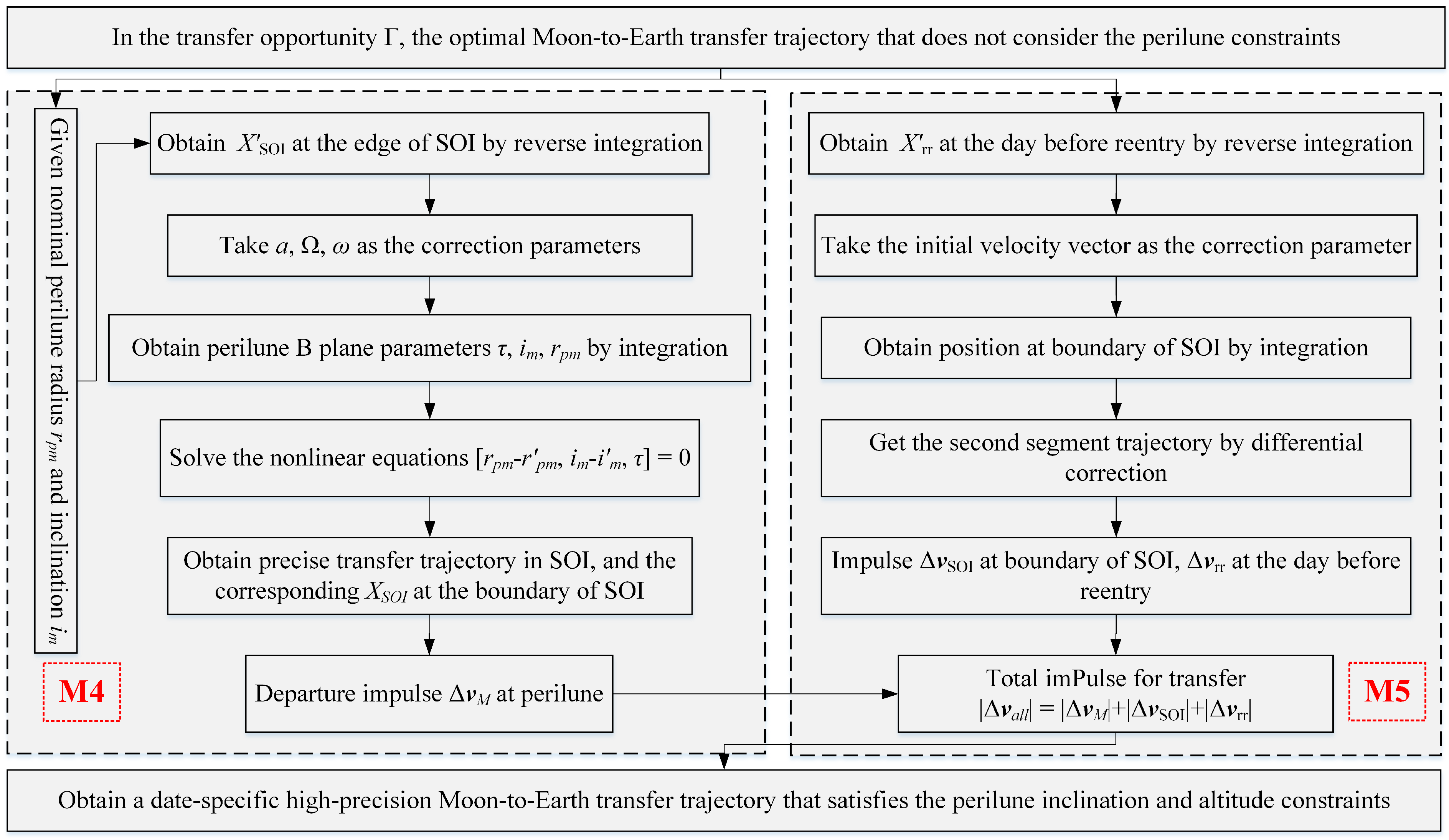
The steps for precise transfer trajectory design in the SOI of the Moon are shown as module M4 in Figure 3.

4.2. Boundary of SOI to the Day before Re-Entry

Compared with the state before the correction, the position and velocity of the probe at the boundary of the SOI of the Moon after the correction have small changes. Thus, the trajectory from the re-entry point to the boundary of the SOI of the Moon needs to be corrected to align with the probe status at the boundary of the SOI.
The correction impulse is applied one day before Earth’s re-entry to align the position of the probe at the boundary of the SOI of the Moon. Then, the whole transfer trajectory is divided into three segments: (1) perilune–boundary of the SOI of the Moon; (2) boundary of the SOI of the Moon–one day before re-entry; and (3) one day before re-entry–re-entry. Three impulses are applied in the whole process, that is, the connection impulse between every two segments in addition to the departure impulse at the perilune of Equation (28).
The third segment of trajectory inverse integration is based on the initial value X i of the re-entry position, and the state of the probe X r r = r r r , v r r on the day before re-entry is obtained under the high-precision dynamic model, where r r r = x r r , y r r , z r r , v r r = v x r , v y r , v z r . Select the terminal constraint as the position of the probe at the boundary of the first segment in the SOI of the Moon obtained above.
The value of the probe velocity increment Δ v r r = Δ v x r , Δ v y r , Δ v z r on the day before re-entry, which makes the position of the probe at the boundary of the SOI of the Moon accurately aligned, is obtained by adopting a B-plane correction. Therefore, the initial velocity on the day before re-entry in the second segment is v r r = v r r + Δ v r r . In order to correspond to the initial state of the probe in the third segment, the velocity increment that should be applied by the probe at the boundary of the SOI of the Moon in the corresponding second segment is Δ v SOI = v SOI v SOI .
The procedures for precise transfer trajectory design out of the SOI of the Moon are shown as module M5 in Figure 3.
Thus far, the high precision Moon-to-Earth transfer trajectory with the time of re-entry T 0 in the opportunity Γ has been obtained, and the total maneuver required by the probe is
Δ v a l l = Δ v M + Δ v SOI + Δ v r r

5. Numerical Simulation and Analysis

In this section, the specific precise transfer trajectory and the opportunity in a year are simulated to verify the reliability of the integrated determination method. Moreover, the effects of several design parameters on the opportunity and performance of the transfer trajectory are also analyzed to provide instructions for parameter selection.

5.1. Opportunity and Specific Precise Trajectory Verification

Firstly, determine the re-entry state in ECEF that meets the re-entry conditions. Select the longitude and latitude of the landing field as λ F = 101 . 45 E , φ F = 41 . 2 N , the re-entry trajectory inclination as i r = 45 , the re-entry velocity as v r e = 10.7 km / s , and the re-entry voyage as S r = 6456 km , that is U r = 58 .
Execute the procedures of module M1 in Figure 2 to obtain the re-entry state of the probe in ECEF as r e = [ 4314.9 , 4783.6 , 851.5 ] km , v e = [ 7.033 , 3.535 , 7.248 ] km / s .
Select a re-entry date of 3 October 2030, for optimal Moon-to-Earth transfer trajectory design. Set the transfer duration to Δ T = 3.0 days, and the re-entry date range is D 1 , D 1 + 1 = [2,462,777.5, 2,462,778.5] (3 October 2030 00:00:00–4 October 2030 00:00:00).
The procedures of module M2 in Figure 2 are implemented to obtain the re-entry time corresponding to the optimal trajectory as JD = 2,462,778.43474 (3 October 2030 22:26:01).
In this case, the re-entry velocity with the transfer duration set to the preset value is adjusted to v r ε = 10.6541 km / s , and the re-entry state of the probe in ECI is r i = [5136.5, 3888.1, 851.5] km , v i = [ 6.501 , 5.147 , 7.217 ] km / s .
The optimal transfer trajectory is shown in Figure 4, and the corresponding radius of the perilune is 2768.5 km .
Analyze the opportunity of the Moon-to-Earth transfer in 2030. Set the re-entry angle as 6 , and calculate the daily optimal transfer trajectory in 2030, and the corresponding perilune altitude change is shown in Figure 5.
Set the altitude deviation limit of the perilune as χ = 50,000 km. The red dotted line in Figure 5 corresponds to χ ; that is, the date when the perilune altitude of the optimal transfer trajectory is lower than this deviation limit is included in the Moon-to-Earth transfer opportunity. It can be seen that the transfer opportunity is about 6–8 days per month, and the opportunity width is about 74 days in 2030.
Similarly, select a re-entry date of 3 October 2030, for precise Moon-to-Earth transfer trajectory design. Choose the inclination and altitude constraints of the perilune as i m = 85 , r p m = 200 km , respectively, and the radius of the SOI of the Moon is selected as r SOI = 66,200 km.
Adopt the procedures of module M4 in Figure 3 to correct the semi-major axis, argument of ascending node, and argument of perihelion corresponding to this state. It is obtained that the corrected state at the boundary of the SOI of the Moon is r SOI = [−186,328.5, −244,850.2, −115,443.3] km , v SOI = [ 0.5633 , 0.5225 , 0.1425 ] km / s .
Table 1 shows the orbital elements at the perilune of the Moon-to-Earth transfer trajectory in the MCI.
If the probe departs from a 200 km altitude circular orbit coplanar with the Moon-to-Earth transfer trajectory, the applied departure impulse is Δ v M = [ 217.8 , 687.1 , 496.2 ] m / s .
Finally, corrections are applied to the second segment of the trajectory, so that the three segments are precisely connected. Perform high-precision inverse integration on the re-entry state X i obtained above, and obtain the state of the probe at the day before re-entry, r r r = [−96,970.8, −157,624.1, −85,389.1] km , v r r = [ 0.9457 , 1.0081 , 0.3950 ] km / s .
Apply the differential correction of module M5 in Figure 3 to correct the velocity v r r , so that the position at the boundary of the SOI of the Moon aligns with the position r SOI obtained in the previous step. The velocity increment on the day before re-entry is Δ v r r = [ 5.2 , 1.2 , 5.8 ] m / s .
Thus, the second and third segments are precisely aligned at the boundary of the SOI of the Moon, and the required velocity increment is Δ v SOI = [ 4.1 , 1.6 , 2.7 ] m / s .
Combining all the above solution processes, the total velocity increment required to obtain the Moon-to-Earth transfer trajectory is Δ v a l l = Δ v M + Δ v SOI + Δ v r r = 888.2 m / s .
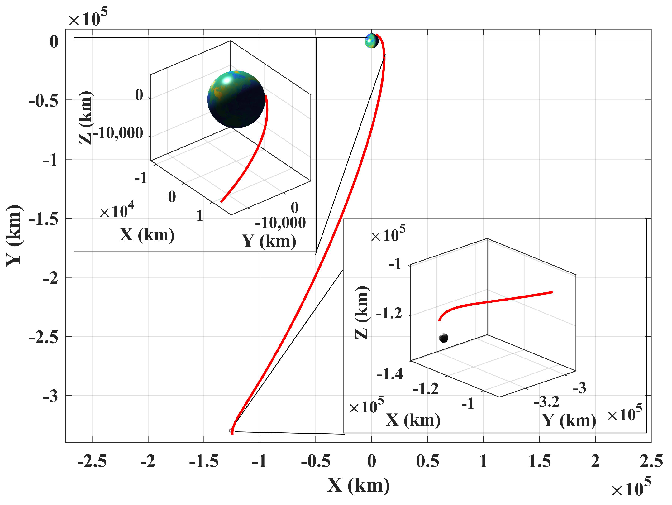
The precise Moon-to-Earth transfer trajectory satisfying all preset constraints is shown in Figure 6.
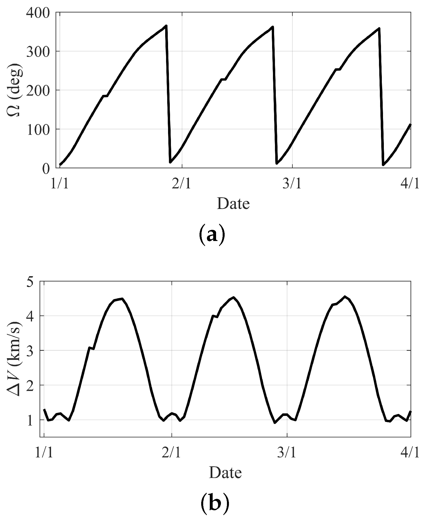
In order to characterize some regularities of the precise transfer trajectory, Figure 7 shows the changes in the right ascension of the ascending node (RAAN) and the total velocity increment required ( Δ V ) for the transfer to reach the perilune in the first three months of 2030.
The RAAN and Δ V of the precise trajectories in the first three months of 2030 change in the same cycle as the perilune altitude in the opportunity screening process in Figure 5. In other words, the RAAN of the perilune of the precise trajectory based on natural transfer changes one circle synchronized with the Moon’s revolution. The Δ V required is strictly related to the perilune altitude of the optimal transfer per day, and the difference in velocity increments is mainly caused by the difference in maneuvers required to correct the perilune altitude.
In addition, Table 2 represents the obtained opportunity in the first month of 2019 to compare with reference [45].
It can be seen that the opportunity obtained in this paper is approximately the same but slightly wider than that in the reference when the perilune altitude deviation limit is χ = 50,000 km. The corresponding minimum Δ V is almost equal to the reference, and the maximum Δ V required is about 1.38 km/s.

5.2. Design Parameters Analysis

There are many design parameters involved in the design process of the opportunity, such as the transfer duration, altitude of the perilune, and so on, while the location of the landing field also affects the design results. Different design parameters have distinct degrees of influence on the distribution of opportunities, the cost of transfer, etc. The analysis of the influence of several design parameters on the distribution law of opportunity and the performance of precise Moon-to-Earth transfer trajectory is as follows.

5.2.1. Position of Landing Site

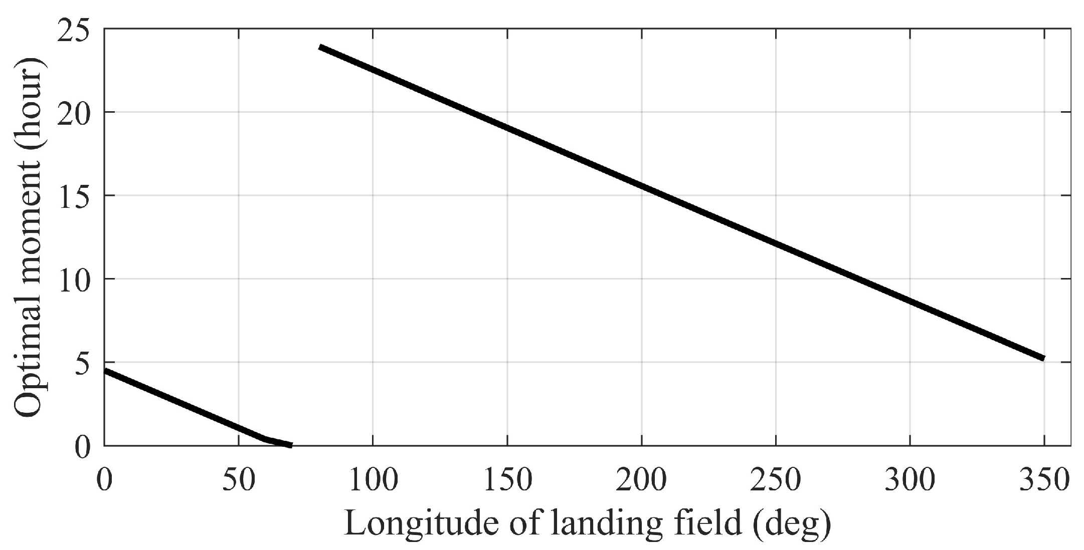
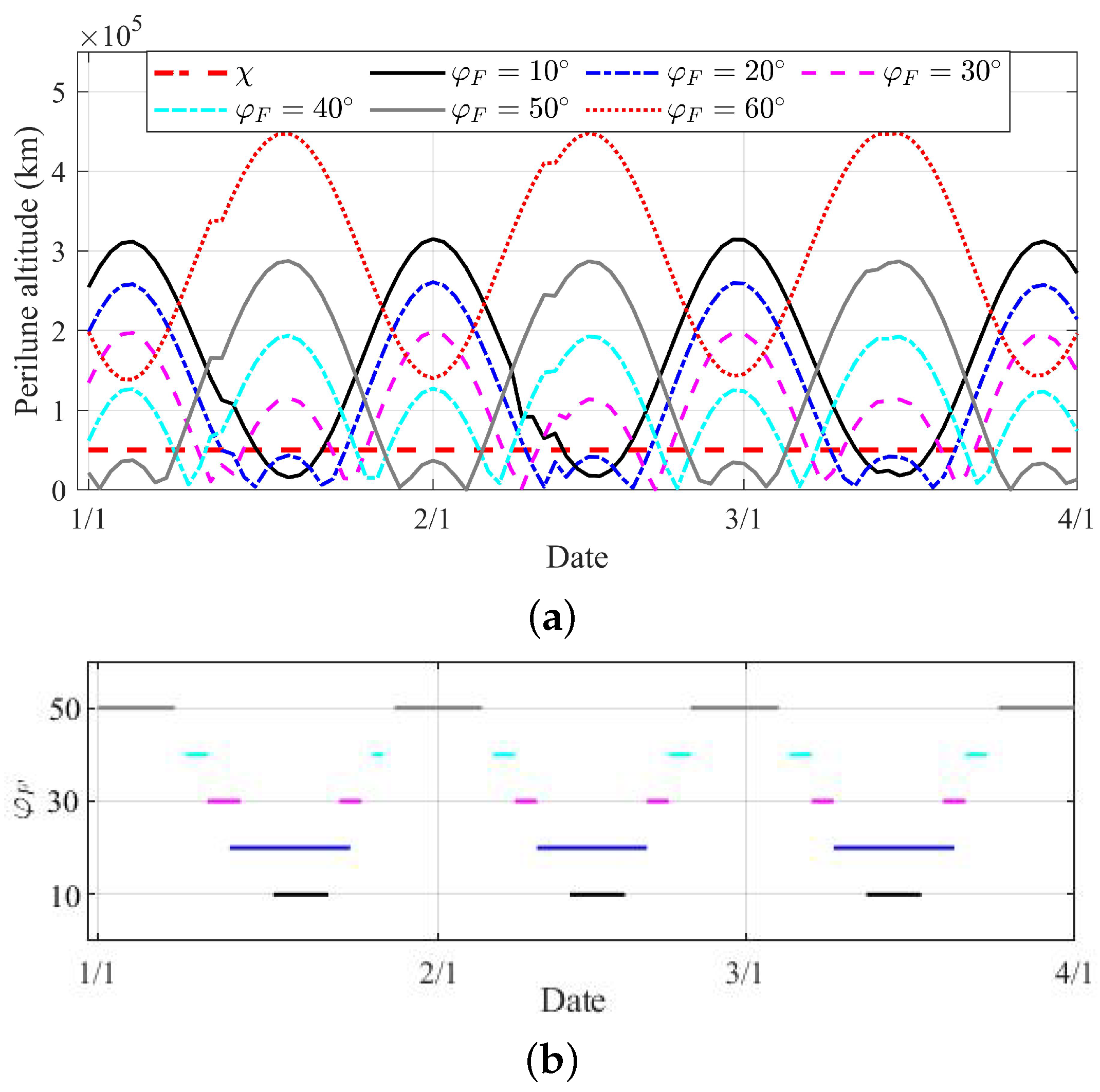
On the premise that other design parameters remain unchanged, the latitude and longitude of the landing field affect the position of the re-entry point according to the geometric relationship of the spherical triangle. Figure 8 reveals the moment distribution in a day based on the single transfer trajectory example when the longitude of the landing field varies in full phase space, while Figure 9 shows the perilune altitudes of several latitudes and the distribution of opportunities when the latitude of the landing field changes within a certain range in the first three months of 2030.
It can be seen from Figure 8 that when the longitude of the landing field changes in the whole space, the daily optimal transfer moment changes with the same trend of longitude. This is easy to understand, for the direction of the velocity of the re-entry point in ECEF will change with the longitude of the landing field, while the angle of the Moon’s revolution changes very little within a day, so the date distribution of opportunities has little changes. On the same day, the directions of the optimal transfer trajectories corresponding to the landing field with different longitudes in the ECI should basically be the same. That is, when the longitude traverses a circle uniformly, the optimal transfer time in a day also changes uniformly within 24 h.
In contrast, the latitude of the landing field has a greater impact on the distribution of opportunities, which is shown in Figure 9. The velocity directions of the re-entry points in ECEF corresponding to different latitudes are different, especially in the z-direction, which leads to the fact that when the latitude changes on a feasible date, the height of the perilune, especially the distance in the z-direction, exceeds the deviation limit. Thus, this opportunity no longer exists. However, correspondingly, when the angle of the Moon can compensate for the z-direction deviation caused by latitude changes on other dates, this date is a new transfer opportunity. Thus, the difference of the latitudes of the landing field leads to the diversification of the transfer opportunity. When the re-entry inclination is set to 45 , the opportunity lengths in the first three months of 2030 are 18 days, 35 days, 18 days, 17 days, and 34 days corresponding to the latitudes of 0 , 10 , 20 , 30 , 40 , and 50 , respectively. It should be noted that the re-entry inclination cannot be smaller than the latitude of the landing field.

5.2.2. Transfer Duration

In this paper, the method of numerical iteration is adopted to adjust the re-entry velocity, so that the duration of the Moon-to-Earth transfer can precisely meet the preset value. At the same time, the shorter the transfer time, the larger the velocity of the probe during the transfer. Given the fact that the magnitude of the relative distances and velocity of the Earth and the Moon vary little, a larger transfer velocity results in greater Moon capture maneuver. Figure 10 shows the change curves of the transfer duration and the total velocity increment Δ V , as well as the atmospheric re-entry velocity. Design parameter settings are the same as in the single transfer trajectory example except for the transfer duration.

5.2.3. Altitude of Perilune

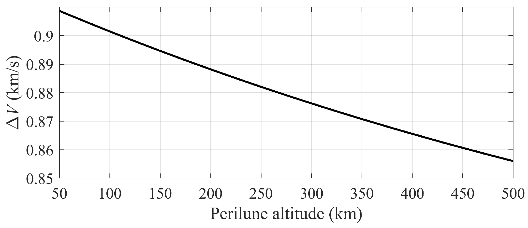
The setting of the values of the nominal altitude of the perilune is only involved in the design of the precise transfer trajectory, so the parameter does not affect the distribution of transfer opportunities. However, the altitude of the perilune closely related to the velocity increments is required to precisely transfer trajectories. Figure 11 reveals the relationship between the velocity increment and the perilune altitude. Design parameter settings are the same as in the single transfer trajectory example except for the altitude of perilune.
The curve in Figure 11 illustrates a negative correlation between the velocity increment and the perilune altitude, which can be explained by the energy difference between orbits. The higher the perilune, the larger the energy of capture orbit. When the probe enters the lunar capture orbit from the higher-energy Moon-to-Earth transfer trajectory, a higher capture orbit energy means a smaller capture velocity increment.

6. Conclusions

Considering Earth re-entry and landing field constraints, an integrated design method for Moon-to-Earth transfer opportunity and precise transfer trajectory is developed. First, this paper innovatively proposes an analytical method to obtain the re-entry state that satisfies reliable ground landing by adopting the theory of spherical geometry. Next, the Moon-to-Earth transfer opportunity is effectively determined by the permitted range of the perilune altitude according to the inverse integration of the obtained re-entry state. Then, the three-impulse Moon-to-Earth transfer strategy is adopted to satisfy the Moon departure condition from any initial inclination in the obtained opportunity. The simulation shows that there is little difference in the width of the Moon-to-Earth transfer opportunity in each month under the fuel constraint. When the deviation limit is 50,000 km, the width of the transfer opportunity in a year is about 74 days. Compared with the traditional patched-conic method, the application of the Earth and Moon gravitational model and the high-precision dynamic model can ensure higher reliability and accuracy of the resulting transfer opportunities. Moreover, the longitude of the landing field is relevant to the optimal transfer moment in a day, while the latitude influences the date distribution of the opportunity. The transfer duration and the altitude of the perilune are both closely related to the fuel consumption of the mission. The proposed design method can provide an effective Moon-to-Earth transfer opportunity and trajectory determination reference for the next stage of the Moon missions of China and other countries.

Author Contributions

F.J. investigated the status of the Moon-to-Earth transfer opportunity and trajectory design. F.J., W.Z. and X.L. studied the integrated determination method, performed the simulations, and revised the manuscript. Q.P. provided research recommendations and checked and revised the manuscript. All authors have read and agreed to the published version of the manuscript.

Funding

This work was supported by the pre-research project for manned space program (Grant No. 202220141031), the National Natural Science Foundation of China (Grant No. 12002028), and the Beijing Institute of Technology Research Fund Program for Young Scholars (Grant No. XSQD-202101012).

Institutional Review Board Statement

Not applicable.

Informed Consent Statement

Not applicable.

Data Availability Statement

Not applicable.

Conflicts of Interest

The authors declare no conflict of interest.

References

  1. Benz, W.; Slattery, W.; Cameron, A. The origin of the Moon and the single-impact hypothesis I. Icarus 1986, 66, 515–535. [Google Scholar] [CrossRef]
  2. Cheng, L.; Wang, Z.; Jiang, F. Real-time control for fuel-optimal Moon landing based on an interactive deep reinforcement learning algorithm. Astrodynamics 2019, 3, 375–386. [Google Scholar] [CrossRef]
  3. Berry, R. Launch window and translunar, lunar orbit, and transearth trajectoryplanning and control for the Apollo 11 lunar landing mission. In Proceedings of the 8th Aerospace Sciences Meeting, Gottingen, Germany, 19–21 January 1970; p. 24. [Google Scholar]
  4. Qiao, D.; Cui, H.; Cui, P. The design of transfer trajectory for Ivar asteroid exploration mission. Acta Astronaut. 2009, 65, 1553–1560. [Google Scholar] [CrossRef]
  5. Qiao, D.; Cui, P.; Cui, H. Proposal for a multiple-asteroid-flyby mission with sample return. Adv. Space Res. 2012, 50, 327–333. [Google Scholar] [CrossRef]
  6. Wang, Y.; Qiao, D.; Cui, P. Analysis of two-impulse capture trajectories into halo orbits of Sun–Mars system. J. Guid. Control Dynam. 2014, 37, 985–990. [Google Scholar] [CrossRef]
  7. Tang, Y.; WU, W.; Qiao, D.; Li, X. Effect of orbital shadow at an Earth-Moon Lagrange point on relay communication mission. Sci. China Inform. Sci. 2017, 11, 211–220. [Google Scholar] [CrossRef]
  8. WU, W.; Tang, Y.; Qiao, D. Design of communication relay mission for supporting lunar-farside soft landing. Sci. China Inform. Sci. 2018, 61, 040305. [Google Scholar] [CrossRef]
  9. Han, H.; Qiao, D.; Chen, H. Optimization of aeroassisted rendezvous and interception trajectories between non-coplanar elliptical orbits. Acta Astronaut. 2019, 163, 190–200. [Google Scholar] [CrossRef]
  10. Han, H.; Qiao, D.; Chen, H.; Li, X. Rapid planning for aerocapture trajectory via convex optimization. Aerosp. Sci. Technol. 2019, 84, 763–775. [Google Scholar] [CrossRef]
  11. Zhou, X.; Cheng, Y.; Qiao, D.; Huo, Z. An adaptive surrogate model-based fast planning for swarm safe migration along halo orbit. Acta Astronaut. 2022, 194, 309–322. [Google Scholar] [CrossRef]
  12. Qiao, D.; Zhou, X.; Zhao, Z.; Qin, T. Asteroid Approaching Orbit Optimization Considering Optical Navigation Observability. IEEE Trans. Aerosp. Electron. Syst. 2022. [Google Scholar] [CrossRef]
  13. Foing, B.; Racca, G.D.; Marini, A.; Evrard, E.; Stagnaro, L.; Almeida, M.; Koschny, D.; Frew, D.; Zender, J.; Heather, J.; et al. SMART-1 mission to the Moon: Status, first results and goals. Adv. Space Res. 2006, 37, 6–13. [Google Scholar] [CrossRef]
  14. Chung, M.K.; Weinstein, S. Trajectory design of lunar South Pole-Aitken Basin sample return mission. In Proceedings of the AIAA/AAS Astrodynamics Specialist Conference and Exhibit, Providence, RI, USA, 16–19 August 2004; p. 4739. [Google Scholar]
  15. Li, X.Y.; Qiao, D. Modeling method and preliminary model of Asteroid Toutatis from Chang’E-2 optical images. Acta Mech. Sin. 2014, 30, 310–315. [Google Scholar] [CrossRef]
  16. Mizutani, H.; Fujimura, A.; Tanaka, S.; Shiraishi, H.; Nakajima, T. Lunar-A mission: Goals and status. Adv. Space Res. 2003, 31, 2315–2321. [Google Scholar] [CrossRef]
  17. Vighnesam, N.; Sonney, A.; Gopinath, N. India’s first lunar mission Chandrayaan-1 initial phase orbit determination. Acta Astronaut. 2010, 67, 784. [Google Scholar] [CrossRef]
  18. Li, Z.; Ye, M.; Cai, Z.; Tang, Z. Automatic stitching method for Chang’E-2 CCD images of the Moon. J. Earth Sci. 2017, 28, 168–179. [Google Scholar] [CrossRef]
  19. Qiao, D.; Cui, P.; Wang, Y.; Huang, J.; Meng, L.; Jie, D. Design and analysis of an extended mission of CE-2: From lunar orbit to Sun–Earth L2 region. Adv. Space Res. 2014, 54, 2087–2093. [Google Scholar] [CrossRef]
  20. Huang, J.; Ji, J.; Ye, P.; Wang, X.; Yan, J.; Meng, L.; Wang, S.; Li, C.; Li, Y.; Qiao, D. The ginger-shaped asteroid 4179 Toutatis: New observations from a successful flyby of Chang’e-2. Sci. Rep. 2013, 3, 3411. [Google Scholar] [CrossRef]
  21. Zhu, M.; Fa, W.; Ip, W.; Huang, J.; Liu, T.; Meng, L.; Yan, J.; Xu, A.; Tang, Z.; Wang, X.; et al. Morphology of asteroid (4179) Toutatis as imaged by Chang’E-2 spacecraft. Geophys. Res. Lett. 2014, 41, 328–333. [Google Scholar] [CrossRef]
  22. Qiao, L.; Chen, J.; Xu, L.; Wan, S.; Cao, H.; Li, B.; Ling, Z. Geology of the Chang’e-5 landing site: Constraints on the sources of samples returned from a young nearside mare. Icarus 2021, 364, 114480. [Google Scholar] [CrossRef]
  23. Wang, Z.S.; Meng, Z.; Gao, S.; Peng, J. Orbit Design Elements of Chang’e 5 Mission. Space Sci. Technol. 2021, 2021, 9897105. [Google Scholar] [CrossRef]
  24. Zhang, H.; Li, J.; Wang, Z.; Guan, Y. Guidance navigation and control for Chang’E-5 powered descent. Space Sci. Technol. 2021, 2021, 9823609. [Google Scholar] [CrossRef]
  25. Pontani, M.; Di Roberto, R.; Graziani, F. Lunar orbit dynamics and maneuvers for Lunisat missions. Acta Astronaut. 2018, 149, 111–122. [Google Scholar] [CrossRef]
  26. Li, L.T.; Zhang, Z.M.; Yang, D. Study of rapid design method for cislunar transfer trajectory. Acta Aeronaut. Astronaut. Sin. 2003, 24, 152–156. [Google Scholar]
  27. Hill, G.W. Researches in the lunar theory. Am. J. Math. 1878, 1, 5–26. [Google Scholar] [CrossRef]
  28. No, T.S.; Lee, J.M.; Jeon, G.E.; Lee, D.R.; Kim, G.H. A study on earth-moon transfer orbit design. Int. J. Aeronaut. Space 2012, 13, 106–116. [Google Scholar] [CrossRef]
  29. Guelman, M. Earth-to-moon transfer with a limited power engine. J. Guid. Control Dyn. 1995, 18, 1133–1138. [Google Scholar] [CrossRef]
  30. Herman, A.L.; Conway, B.A. Optimal, low-thrust, earth-moon orbit transfer. J. Guid. Control Dyn. 1998, 21, 141–147. [Google Scholar] [CrossRef]
  31. Jiang, F.; Baoyin, H.; Li, J. Practical techniques for low-thrust trajectory optimization with homotopic approach. J. Guid. Control Dyn. 2012, 35, 245–258. [Google Scholar] [CrossRef]
  32. Wang, Y.M.; Qiao, D.; Cui, P.Y. Design of low-energy transfer from lunar orbit to asteroid in the Sun-Earth-Moon system. Acta Mech. Sin. 2014, 30, 966–972. [Google Scholar] [CrossRef]
  33. De Grossi, F.; Marzioli, P.; Cho, M.; Santoni, F.; Circi, C. Trajectory optimization for the Horyu-VI international lunar mission. Astrodynamics 2021, 5, 263–278. [Google Scholar] [CrossRef]
  34. Qi, Y.; de Ruiter, A. Trajectory correction for lunar flyby transfers to libration point orbits using continuous thrust. Astrodynamics 2021, 6, 285–300. [Google Scholar] [CrossRef]
  35. Jia, F.; Qiao, D.; Han, H.; Li, X. Efficient optimization method for variable-specific-impulse low-thrust trajectories with shutdown constraint. Sci. China Technol. Sci. 2022, 65, 581–594. [Google Scholar] [CrossRef]
  36. Circi, C.; Teofilatto, P. On the dynamics of weak stability boundary lunar transfers. Celest. Mech. Dyn. Astr. 2001, 79, 41–72. [Google Scholar] [CrossRef]
  37. Gómez, G.; Koon, W.S.; Lo, M.; Marsden, J.E.; Masdemont, J.; Ross, S.D. Connecting orbits and invariant manifolds in the spatial restricted three-body problem. Nonlinearity 2004, 17, 1571–1606. [Google Scholar] [CrossRef]
  38. Belbruno, E.; Gidea, M.; Topputo, F. Weak stability boundary and invariant manifolds. SIAM J. Appl. Dyn. Syst. 2010, 9, 1061–1089. [Google Scholar] [CrossRef]
  39. Zeng, H.; Zhang, J. Design of impulsive Earth-Moon Halo transfers: Lunar proximity and direct options. Astrophys. Space Sci. 2016, 361, 328. [Google Scholar] [CrossRef]
  40. Gao, Y.D. Research on the Earth-Moon Space Transfer Orbit of the Lunar Probe. Ph.D. Thesis, National University of Defense Technology, Changsha, China, 2008. [Google Scholar]
  41. Zhang, L.; Yu, D.; Zhang, H. Preliminary design and characteristic analysis of Moon-to-Earth transfer trajectories. Chin. Space Sci. Technol. 2011, 31, 62–73. [Google Scholar]
  42. Robinson, S.; Geller, D. A simple targeting procedure for lunar trans-earth injection. In Proceedings of the AIAA Guidance, Navigation, and Control Conference, Chicago, IL, USA, 10–13 August 2009; p. 6107. [Google Scholar]
  43. He, B.; Li, H.; Shen, H.; Peng, Q. Coupled design of landing window and point return orbit for manned lunar landing mission. J. Nat. Univ. Defense Technol. 2017, 39, 11–16. [Google Scholar]
  44. Feng, F.; Zhang, Y.S. Application and analysis of an improved multiconic method in trajectory design of the lunar south pole return mission. Proc. Mech. Eng. Part 2018, 232, 1063–1076. [Google Scholar] [CrossRef]
  45. Zheng, A.; Zhou, J. A search strategy of back windows for moon-to-earth trajectories directly returning to the earth. Acta Aeronaut. Astronaut. Sin. 2014, 35, 2243–2250. [Google Scholar]
  46. Cho, D.H.; Chung, Y.; Bang, H. Trajectory correction maneuver design using an improved B-plane targeting method. Acta Astronaut. 2012, 72, 47–61. [Google Scholar] [CrossRef]
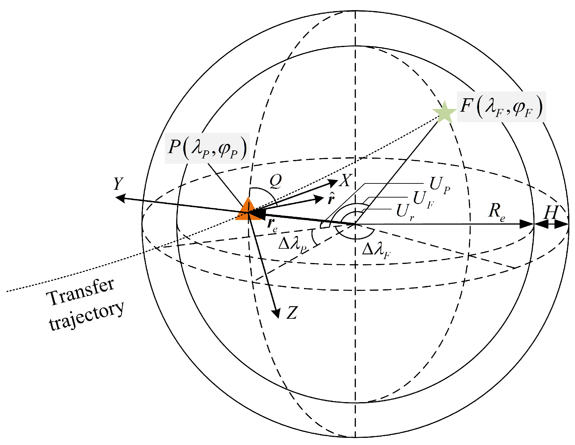
Figure 1. Re-entry coordinate frame O X Y Z and parameters of re-entry trajectory.
Applsci 12 08716 g001
Figure 2. Flowchart for feasible transfer trajectory and opportunity determination. M1 shows the procedures for re-entry state determination; M2 shows the steps for optimal Moon-to-Earth trajectory design; M3 reveals the transfer opportunity screening process.
Applsci 12 08716 g002
Figure 3. Flowchart for precise transfer trajectory design. M4 shows the procedures for precise trajectory design in SOI of the Moon; M5 presents the precise trajectory design out of SOI of the Moon.
Applsci 12 08716 g003
Figure 4. The optimal transfer trajectory of 3 October 2030. The trajectories near the Earth and the Moon are also shown in magnified form.
Applsci 12 08716 g004
Figure 5. Transfer opportunity screened by the altitude deviation limit of perilune. The dotted lines indicate the preset perilune altitude deviation limit.
Applsci 12 08716 g005
Figure 6. The precise transfer trajectory of 3 October 2030. The trajectories near the Earth and the Moon are also shown in magnified form. The three maneuvers divide the entire trajectory into three segments.
Applsci 12 08716 g006
Figure 7. RAAN and Δ V of the precise trajectories in the first three months of 2030. (a) The RAAN of the perilune in the first three months of 2030; (b) The Δ V required at the perilune in the first three months of 2030.
Applsci 12 08716 g007
Figure 8. Relationship between longitude of landing field and optimal re-entry moment in a day.
Applsci 12 08716 g008
Figure 9. Opportunity distribution about several latitudes of landing field in the first three months of 2030. (a) Variation in the natural perilune altitudes at different latitudes; (b) Opportunity distribution for different latitudes.
Applsci 12 08716 g009
Figure 10. Relationship between transfer duration and velocity increment and re-entry velocity. (a) Δ V to the transfer duration; (b) The re-entry velocity to the transfer duration.
Applsci 12 08716 g010
Figure 11. Relationship between velocity increment and perilune altitude.
Applsci 12 08716 g011
Table 1. Orbital elements at perilune of precise Moon-to-Earth transfer trajectory.
Orbital Elementsa/kme i / Ω / ω / f /
Value−4808.31.403085.0291.055.30
Table 2. Comparison of the obtained opportunity between this paper and the reference.
Source γ Δ T OpportunityMinimum Δ V
Paper 6 3 days1 January–4 January, 25 January–31 January889.5 m/s
Reference [45] 6 3 days1 January–3 January, 26 January–31 January890.1 m/s
Publisher’s Note: MDPI stays neutral with regard to jurisdictional claims in published maps and institutional affiliations.