Research on 3D Digital Technological Process of Construction Products with Model-Based Definition

Abstract
:1. Introduction
2. Related Work
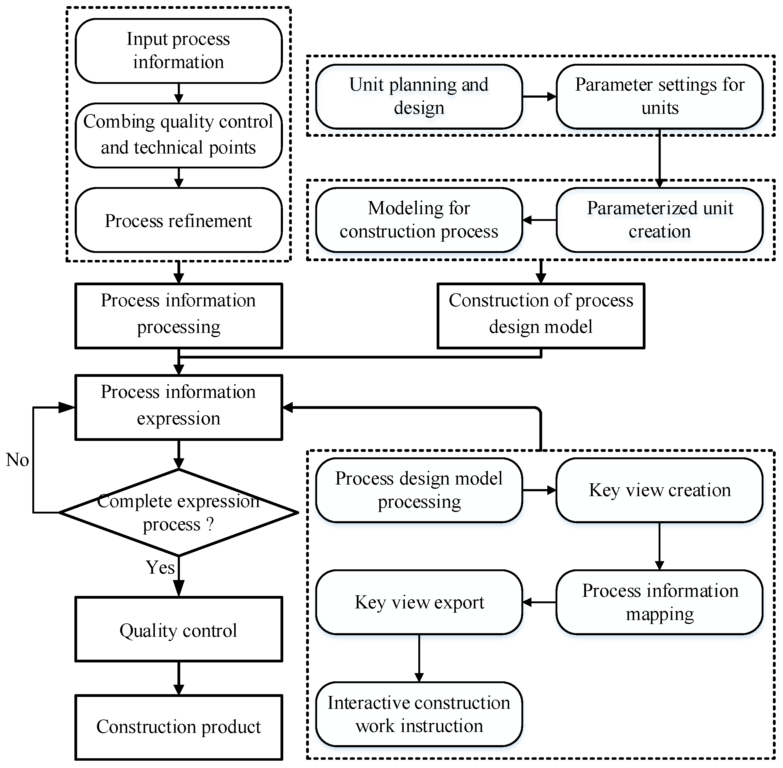
3. Methodology
3.1. Process Information Processing
- 1.
- Combing quality control and technical points
- 2.
- Technological process refinement
3.2. Process Design Model
- 1.
- Parameterized unit creation
- Geometric information parameters.
- Material property parameters.
- Positioning reference parameters.
- Engineering quantity calculation parameters.
- Production, processing, and inspection of relevant parameters.
- 2.
- Modeling for the construction process
3.3. Process Information Expression
- 1.
- Process design model processing
- 2.
- Key view creation
- 3.
- Process information mapping
- 4.
- Export of key views
- 5.
- Interactive construction work instruction
3.4. Digital Expression Method of Construction Process Based on the MBD Technology
4. Application Examples and Discussion
4.1. Background and Data Source
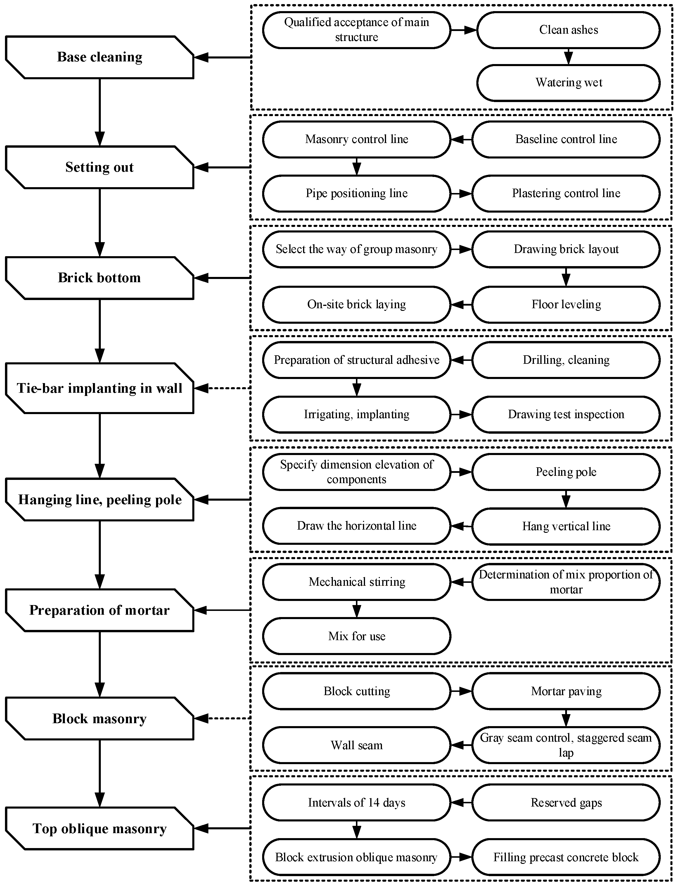
4.2. Infill Wall Masonry Process Information Expression
4.2.1. Infill Wall Masonry Process Information Processing
- 1.
- Combing quality and technical control points
- 2.
- Technological process refinement
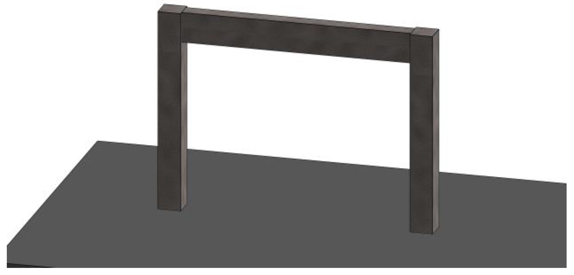
4.2.2. Infill Wall Masonry Process Design Model
- 1.
- Parameterized unit creation
- 2.
- Modeling for the construction process
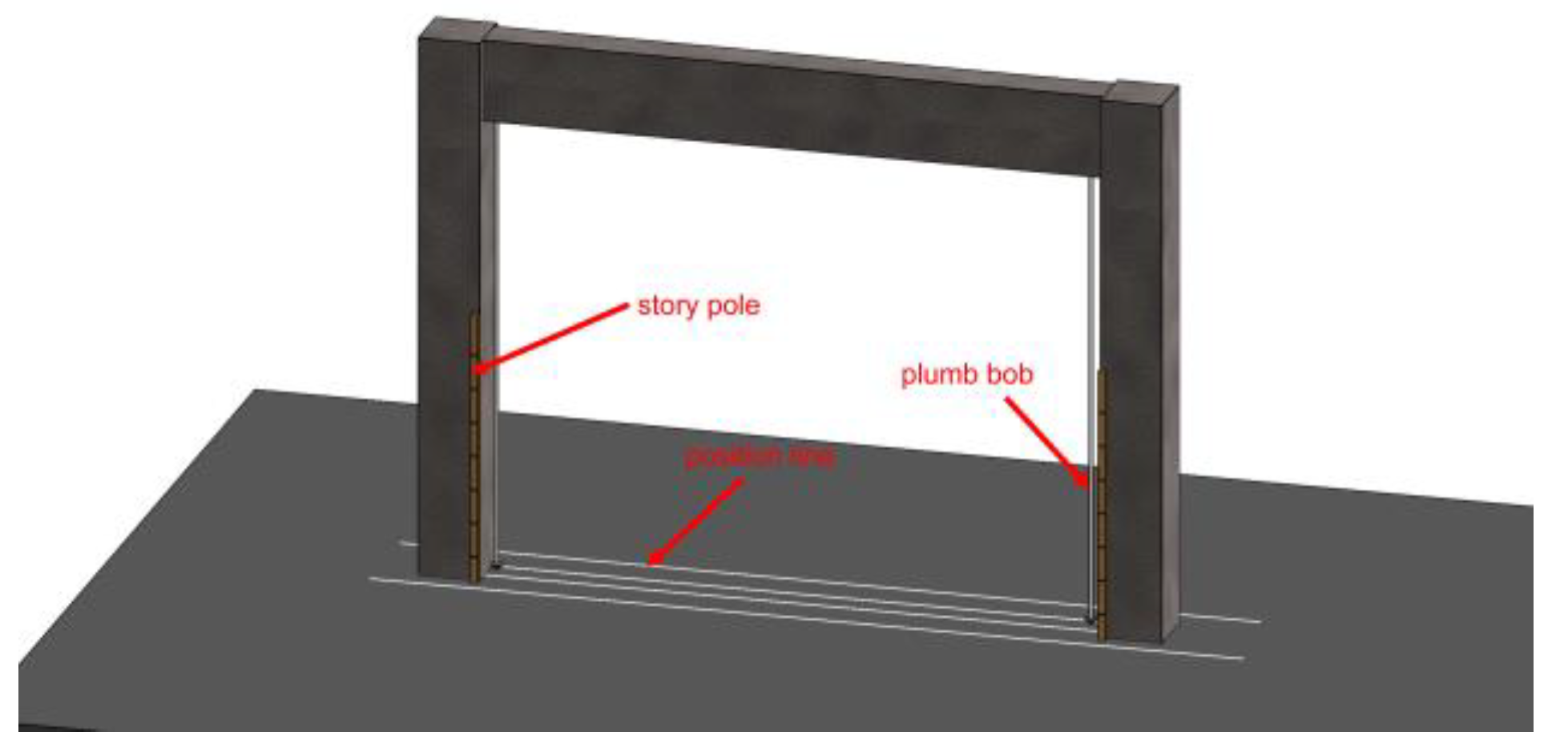
4.2.3. Infill Wall Masonry Process Information Expression
- 1.
- Infill wall masonry process design model processing
- 2.
- Creation of the infill wall masonry key view
- 3.
- Infill wall masonry process information mapping
- 4.
- Export the key view of infilled wall masonry
- 5.
- Formation of an interactive construction instruction book for masonry infill wall
4.3. Discussion
- Express the evolution of the architectural production process by making full use of the advantages of three-dimensional space, taking the three-dimensional digital model as the core, and according to the dynamic changes in the three-dimensional model. In addition, this paper innovatively attaches the process information to the three-dimensional model for expression, which overcomes many limitations of the two-dimensional expression methods (e.g., drawings, texts, and pictures), effectively improves the understanding of the process details by construction personnel and management personnel, reduces the incorrect operations in the process of building products, and avoids the waste of resources caused by improper process operation. For example, construction personnel and management personnel can view the three-dimensional model and various information interactively and visually in the construction work instructions and key views, thereby increasing their understanding of the process. As emphasized by Wang and Sepehr, interactive and 3D visualization virtual environments can improve the quality of learning and understanding [23,24].
- By taking advantage of desktop virtual reality, construction and management personnel can display and use 3D digital models on fixed devices (such as PCs or large screens) and mobile devices (such as tablets) without complicated operational training. Compared with expensive virtual reality devices and augmented reality systems, this is more suitable for cost management in construction sites.
- By taking the construction steps of building products as the basic unit of technological process expression and using the process-based dynamic expression, our method is more refined, structured, and standardized than the traditional construction technology disclosure and quality control scheme, improving the control of construction personnel and management personnel on the details of product construction, reducing the quality defects hidden inside the building products, and avoiding the quality problems caused by internal defects.
- The three-dimensional digital model is created by BIM technology, and the construction products in the construction process are accurately reproduced in the digital environment. The quality control and quality management of the construction process are conducted according to the three-dimensional digital model and the process information attached to this. Compared with the traditional process management method, our method has obvious advantages. For example, our method can achieve the timely detection of many problems in the construction process based on the three-dimensional model of different process nodes and building products in the construction process of shape, location, size, etc.
- The three-dimensional geometric model based on BIM technology has the characteristic of parameterization, which can realize the reuse and quick adjustment of the construction process of building products through parameter transformation, and is more efficient than the complicated traditional process document creation process. In addition, the multidimensional integration of the MBD technology has obvious advantages. It can integrate the information of different dimensions, such as size, tolerance, material, technical requirements, and specification standards, into the three-dimensional model. Additionally, in terms of the data source for information transmission, it has more advantages than other technologies.
5. Conclusions
Supplementary Materials
Author Contributions
Funding
Institutional Review Board Statement
Informed Consent Statement
Data Availability Statement
Acknowledgments
Conflicts of Interest
References
- Gunasinghe, P.; Silva, S.D. The effect of poor workmanship in civil engineering construction sites and strategies for improving workmanship. Int. J. Manag. Concepts Philos. 2021, 14, 312–331. [Google Scholar] [CrossRef]
- Ali, A.S.; Wen, K.H. Building defects: Possible solution for poor construction workmanship. J. Build. Perform. 2011, 2, 59–69. [Google Scholar]
- Fromsa, A.; Ararsa, W.; Quezon, E.T. Effects of Poor Workmanship on Building Construction and Its Implication to Project Management Practice: A Case Study in Addis Ababa City. Xi’an Dianzi Keji Daxue Xuebao J. Xidian Univ. 2020, 14, 1174–1188. [Google Scholar]
- Dave, B.; Appleby, C. Striving for continuous process improvement-a construction case study. In Proceedings of the Indian Lean Construction Conference (ILCC 2015), Mumbai, India, 6–7 February 2015. [Google Scholar]
- Atanasova, T. Main factors influencing digitization in construction companies. In Proceedings of the International Conference Information and Communication Technologies in Business and Education, Azerbaijan, Baku, 23–25 October 2019; pp. 116–125. [Google Scholar]
- Katz, R.L.; Koutroumpis, P. Measuring Socio-Economic Digitization: A Paradigm Shift; Columbia Institute for Tele-Information: New York, NY, USA, 2012. [Google Scholar]
- Huang, R.; Zhang, S.; Bai, X.; Xu, C. Multi-level structuralized model-based definition model based on machining features for manufacturing reuse of mechanical parts. Int. J. Adv. Manuf. Technol. 2014, 75, 1035–1048. [Google Scholar] [CrossRef]
- Zhu, H.; Li, J. Research on three-dimensional digital process planning based on MBD. Kybernetes 2018, 47, 816–830. [Google Scholar] [CrossRef]
- Goher, K.; Shehab, E.; Al-Ashaab, A. Model-Based Definition and Enterprise: State-of-the-art and future trends. Proc. Inst. Mech. Eng. Part B J. Eng. Manuf. 2021, 235, 2288–2299. [Google Scholar] [CrossRef]
- Zhu, W.; Bricogne, M.; Durupt, A.; Remy, S.; Li, B.; Eynard, B. Implementations of model based definition and product lifecycle management technologies: A case study in Chinese aeronautical industry. IFAC-PapersOnLine 2016, 49, 485–490. [Google Scholar] [CrossRef]
- Liu, J.; Shi, G. Quality control of a complex lean construction project based on KanBIM technology. EURASIA J. Math. Sci. Technol. Educ. 2017, 13, 5905–5919. [Google Scholar] [CrossRef]
- Lou, J.; Xu, J.; Wang, K. Study on construction quality control of urban complex project based on BIM. Procedia Eng. 2017, 174, 668–676. [Google Scholar] [CrossRef]
- Wang, J.; Sun, W.; Shou, W.; Wang, X.; Wu, C.; Chong, H.-Y.; Liu, Y.; Sun, C. Integrating BIM and LiDAR for real-time construction quality control. J. Intell. Robot. Syst. 2015, 79, 417–432. [Google Scholar] [CrossRef]
- Karji, A.; Rokooei, S.; Mainzer, E. Integration of lidar and augmented reality for construction quality control, a conceptual framework. In Proceedings of the CSCE 2021 Annual Conference, Las Vegas, NV, USA, 26–29 May 2021. [Google Scholar]
- Al-Adhami, M.; Wu, S.; Ma, L. Extended reality approach for construction quality control. In Proceedings of the CIB World Building Congress, Hong Kong, China, 17–21 June 2019. [Google Scholar]
- Mirshokraei, M.; de Gaetani, C.I.; Migliaccio, F. A web-based BIM–AR quality management system for structural elements. Appl. Sci. 2019, 9, 3984. [Google Scholar] [CrossRef]
- Alemanni, M.; Destefanis, F.; Vezzetti, E. Model-based definition design in the product lifecycle management scenario. Int. J. Adv. Manuf. Technol. 2011, 52, 1–14. [Google Scholar] [CrossRef] [Green Version]
- Wan, N.; Mo, R.; Liu, L.; Li, J. New methods of creating MBD process model: On the basis of machining knowledge. Comput. Ind. 2014, 65, 537–549. [Google Scholar] [CrossRef]
- Zhou, Q.Z.; Deng, L. MBD based automotive products process planning technology. Appl. Mech. Mater. 2011, 88–89, 570–575. [Google Scholar] [CrossRef]
- Liu, X.; Li, X.; Xing, J.; Chen, H.; Ni, Z. Integrating modeling mechanism for three-dimensional casting process model based on MBD. Int. J. Adv. Manuf. Technol. 2018, 94, 3145–3162. [Google Scholar] [CrossRef]
- Zhang, H.L.; Liao, W.H.; Guo, Y.; Yang, W.A. An approach to generate three dimensional machining process model according to information from design model based on definition. Key Eng. Mater. 2016, 693, 1684–1692. [Google Scholar] [CrossRef]
- Geng, J.; Zhang, S.; Yang, B. A publishing method of lightweight three-dimensional assembly instruction for complex products. J. Comput. Inf. Sci. Eng. 2015, 15, 031004. [Google Scholar] [CrossRef]
- Alizadehsalehi, S.; Hadavi, A.; Huang, J.C. Virtual reality for design and construction education environment. In Proceedings of the AEI 2019: Integrated Building Solutions—The National Agenda, Tysons, VA, USA, 3–6 April 2019; pp. 193–203. [Google Scholar]
- Wang, P.; Wu, P.; Wang, J.; Chi, H.L.; Wang, X.Y. A Critical Review of the Use of Virtual Reality in Construction Engineering Education and Training. Int. J. Environ. Res. Public Health 2018, 15, 1204. [Google Scholar] [CrossRef] [PubMed] [Green Version]


| Serial Number | Name of the Material | Specification | Remark |
|---|---|---|---|
| 1 | Steel reinforcement | Φ16 | Preservative treatment |
| 2 | Vapor compression concrete block | B06: 600 × 240 × 200 mm B06: 215 × 240 × 200 mm | Strength grade A3.5, block density ≤6.5 KN/ m3 Product age greater than 28 days, moisture content less than 30% |
| 3 | Autoclaved sand-lime brick | MU10: 200 × 95 × 53 mm | / |
| 4 | Cement | Grade 32.5 ordinary portland cement | / |
| 5 | Sand | Medium sand | 5 mm sieve |
| 6 | Additive | Finely ground raw lime powder and fly ash | Raw lime powder ripening no less than 2 days |
| Construction Process | Technical Essential | Quality Problems |
|---|---|---|
| Preparation for construction |
|
|
| Measurement and discharge line |
|
|
| Wall reinforcement |
|
|
| Mortar preparation |
|
|
| Wall construction |
|
|
| Content | 2D Process Information Expression | 3D Process Information Expression | Evaluation |
|---|---|---|---|
| Synergy between process information and 3D model | Separate | Integrated | |
| Size of process file | 25.6 M | 14.6 M/11.1 M/5.1 M | Reduced by 42.9%/56.6%/80.1% |
| Format of process file | DOCX + XLS + BIM model | Single XLS/EXE/SMG | |
| Can it control and simulate process expression? | No | Yes | |
| Can it be used as a basis for quality control? | No | Yes | |
| Can it accurately express the process? | No | Yes | |
| Is it interactive? | No | Yes | |
| Time to understand process information | 1 h | 0.4 h | Reduced by 60% |
| Times of process information explanation | 3 | 1 | Reduced by 66.7% |
Publisher’s Note: MDPI stays neutral with regard to jurisdictional claims in published maps and institutional affiliations. |
© 2022 by the authors. Licensee MDPI, Basel, Switzerland. This article is an open access article distributed under the terms and conditions of the Creative Commons Attribution (CC BY) license (https://creativecommons.org/licenses/by/4.0/).
Share and Cite
Liu, Y.; Jia, L.; Wu, H.; Huang, X. Research on 3D Digital Technological Process of Construction Products with Model-Based Definition. Appl. Sci. 2022, 12, 8585. https://doi.org/10.3390/app12178585
Liu Y, Jia L, Wu H, Huang X. Research on 3D Digital Technological Process of Construction Products with Model-Based Definition. Applied Sciences. 2022; 12(17):8585. https://doi.org/10.3390/app12178585
Chicago/Turabian StyleLiu, Yang, Lu Jia, Han Wu, and Xing Huang. 2022. "Research on 3D Digital Technological Process of Construction Products with Model-Based Definition" Applied Sciences 12, no. 17: 8585. https://doi.org/10.3390/app12178585
APA StyleLiu, Y., Jia, L., Wu, H., & Huang, X. (2022). Research on 3D Digital Technological Process of Construction Products with Model-Based Definition. Applied Sciences, 12(17), 8585. https://doi.org/10.3390/app12178585