Abstract
Bone drilling is a common surgery procedure. The drill bit shape directly affects the drilling force. Excessive drilling force may cause bone damage. In this work, on the premise of analyzing and comparing several finite element method (FEM) simulation results for drill bit of 5 mm in diameter commonly used in medical practice, a combination of drilling speed and feed rates which can minimize the drilling force for drilling parameters is determined. Then, the effects of the drill bit shape parameters including helix angle, point angle and edge radius on the drilling force are simulated by using the obtained drilling parameters, and after validation the FEM analysis results show that their variation trend is the same as the experimental one. Then, the optimum bit structure parameters are obtained through the following research: (1) the prediction model of the relationship between drill edge parameters and drilling force is established based on the result of FEM of the drilling process; (2) A particle swarm optimization algorithm is used to obtain the optimal matching parameters of the bit structure; (3) The priority order of the influence of the parameters of the bit on the drilling force is analyzed. The results show that the order of the influence is: the edge radius is the largest, the point angle is the second, and the helix angle is the smallest. The optimum combination of bit structure is that point angle, helix angle and edge radius are 95°, 35°, and 0.02 mm, respectively.
1. Introduction
A standard twist drill is one of the most common tools in orthopedic surgery. The cutting-edge structure of standard twist drills often leads to high drilling force or temperature. Therefore, it is necessary to fully understand drilling performance and optimize drill structure parameters to reduce drilling force, thermal damage, and bone recovery time. Larger drilling forces can lead to cracks in bone around the borehole [1], poor quality of the borehole [2], and even permanent necrosis of bone [3], which can easily lead to pathological fractures [4]. According to reports, shank implants fail between 2.1% and 7.1% due to large drilling force [5,6]. Therefore, the bone drilling process needs to minimize drilling force.
The effects [7] of various parameters on the process in drilling of the bone, such as bit diameter, feed rate, depth of the borehole, bit geometry, bit material, and drilling method, are described. In the past period, the study of the bone drilling process on the drilling force and drilling temperature is limited, and the research on the drill bit is summarized as follows.
Technological parameters are studied by researchers have shown that the drilling force and temperature are affected. Still, the cutting-edge structure affects not only the drilling force and temperature but also the bit location and drilling quality. Itoh et al. [8] discussed the influence of cutting-edge shape and depth on the cutting law of femur drilling and concluded that a small rake angle could help reduce cutting force.
Augustin et al. [9] studied the effects of bit diameter, point angle, drilling speed, feed rate, and external cooling on bone thermal necrosis in drilling of the porcine femur. The results show that the increase in bit diameter and rotation speed will lead to the increase in drilling temperature, the change in point angle has little effect on the temperature, and the temperature decreases when the feed rate increases.
Udiljak et al. [10] studied the effects of rotational speed, feed rate, point angle, and bit geometry on drilling force and temperature. The results show that rotary speed has little effect on drilling force and is proportional to the maximum temperature. The feed rate is proportional to drilling force and inversely related to the drilling temperature.
Lee et al. [11] studied heat transfer models in drilling of bovine femur. They proposed a new thermal model for orthopedic drilling, in which the maximum temperature increases with spindle speed, feed rate, and point angle and decreases with bit diameter and helix angle. The influence of spindle speed, feed speed, point angle, bit diameter, and helix angle on the maximum drilling temperature is discussed.
Often, a much bigger point angle weakens the tool’s ability to center itself, resulting in a rounded vertex. However, the point angle of the drill is greater than 90°, resulting in less heat generated and, therefore, could be the suitable angle [12]. The point angle of less than 90° facilitates cartilage and chip flow penetration, reduces deviation from drilling target, increases radial force, and reduces axial force. It is generally believed that increasing the point angle increases drilling force when the bit enters the cortex [13]. Karaca et al. [14] concluded that larger point angles and drilling speeds were unsuitable for achieving minimum temperatures.
A helix angle, also known as groove angle, can be defined as the angle between the groove edge and the bit spindle. A notch is a groove in the bit that provides a path for cutting debris from the hole. Its value usually ranges from 13° to 35° [15].
Most researchers have concluded, respectively, that helix angles of 28° [13,16], 30° [17], and 27°–28° [18] have minimum temperatures, drilling forces, and torque. Hillary and Shuaib [19] optimized bit geometry using high-speed steel bits with a helix angle of 23°. Saha et al. [20] applied a parabolic groove to the surgical bit. They obtained that a helix angle of 36° is the best geometrical parameter for the minimum drilling temperature and force.
Cutting edge radius, also known as edge radius and tooltip radius, can be defined as the nominal blunt circle radii of the cutting edge, measured in the plane of the cutting edge method. The study results by Moufki and Molinari [21] showed that the tangential and axial cutting forces decrease with the increase in tip radius, but the radial forces increase. In terms of experiments, tests conducted by Endres and Kountanya [22], Kevin and Hui [23], and Tang [24] show that tangential cutting forces increase with the increase in the tip radius. In addition, Horvath [24] and Tang et al. [25] presented an empirical model of cutting forces related to the tip radius. The results show that radial and tangential components of the cutting force increase while the feed component decreases with the increase in the tip radius. The effect of tool tip radius on the cutting temperature was demonstrated only by Kishawy [26], which emphasizes that the cutting temperature decreases with the tool tip radius.
Through literature analysis, it is found that there are different opinions on the influence of drill bit shape on drilling temperature and drilling force. As a result, the optimum parameters of helix angle are different. There are also different views on the tip radius.
Researchers studied a single geometrical parameter of drill bit and not multiparameter. Therefore, based on the current research, further optimization is necessary to obtain the best parameters to optimize cutting conditions and to achieve low damage bone drilling. Meanwhile, the cutting-edge structure design of the bit is the key to influencing the drilling force, temperature, and positioning. The variation law of the influence of bit structure on drilling force needs further study.
Biomechanical finite element simulation techniques have been widely used [27]. However, in the simulation study of bone drilling, the previous studies mainly focus on the influence of drilling parameters on drilling force and temperature [28]. Currently, two problems still need to be further studied: (1) the influence of main bit structure parameters on drilling force; (2) the design and optimization of bit structure using optimization algorithm. Therefore, this work aims at these two problems to do research so that it may provide a theoretical basis for selecting the appropriate drill bit shape in the further study of bone drilling.
2. Construction and Verification of Finite Element Model
Finite element simulation method provides a more convenient and low-cost way to evaluate concepts and details that can determine experimental processes or replace physical experiments. Here, the finite element establishment is detailed as follows.
2.1. Parameters Setting of Finite Element Model
Figure 1 is simplified bit geometry. Figure 2 is the finite element model of the tool and material established by using software Advantedge 7.1. (Third Wave Systems, Eden Prairie, MN, USA) Drills of 5 mm [29] in diameter are used in this study.
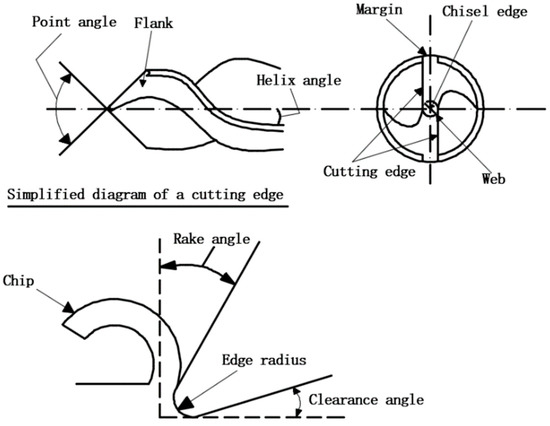
Figure 1.
Simplified bit geometry.
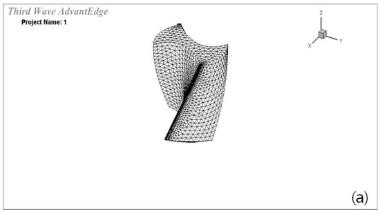
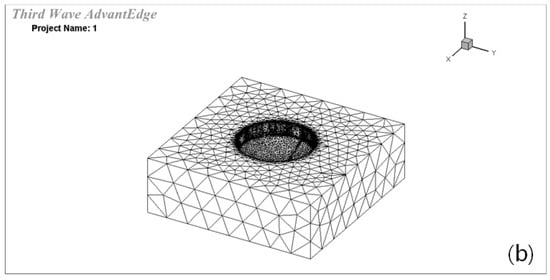
Figure 2.
(a,b) The finite element model of the tool and material.
Since bone material is a multi-tissue composite material, it is transversely characterized by isotropy and is anisotropic in the orthogonal direction [30]. In this paper, bone is studied as isotropic material in the establishment of a finite element model. Table 1 lists the properties of the drill bit and bone material [4,30].

Table 1.
Drill bit and bone material properties.
Material properties must be accurately defined in finite element analysis as a critical factor affecting cutting. Experiments have shown that bone tissue exhibits significant anisotropy. However, to reduce the simulation model’s complexity and solution time, most finite element analyses define bones as isotropic materials. Johnson-Cook models can simultaneously represent the characteristics of materials with temperature, strain, and strain rate changes and are widely used in cutting simulation analysis of bones, with expressions shown in (1) and model parameters as shown in Table 2.
where, is flow stress, A is the yield stress (MPa); B is the work hardening modulus (MPa); C is the strain sensitivity coefficient; n is the hardening coefficient; T is the temperature of the bone, Tm is the melting point of the material (153 °C); T0 is the room temperature (25 °C); epsilon is the strain; epsilon 0 is the reference strain.

Table 2.
Parameters of the Johnson-Cook model [31,32].
Table 2.
Parameters of the Johnson-Cook model [31,32].
| A | B | n | m | C | ε |
|---|---|---|---|---|---|
| 50 | 101 | 0.08 | 1.03 | 0.03 | 0.001 |
2.2. Determination of Major Drilling Parameters
In order to accurately analyze the variation in drilling force during bone drilling, the full factor simulation and analysis of different drilling parameters are carried out. The rotating speeds are 700 r/min, 1100 r/min [31], 1500 r/min, 1900 r/min [33], and the feed quantities are 0.03 mm/r [18], 0.07 mm/r, 0.11 mm/r, 0.15 mm/r [33]. The test results are shown in Figure 3a. Figure 3b shows the variation in drilling force at 1100 r/min and feed rate of 0.03 mm/r, respectively. At a drilling rate of 1100 r/min, the average value of drilling force at different feed rates is as shown in Figure 3c, and at a feed rate of 0.03 mm/r is 40 N.
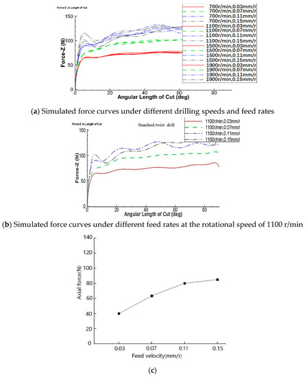
Figure 3.
Variation of the drilling force with drilling parameters.
2.3. Influence of Bit Structure Parameters on Drilling Force
Drill bits with excellent bit structure parameters can be used by surgeons easily and reduce mechanical damage to bones. However, because there are more parameters of the cutting edge and their influences on the drilling process are different, i.e., the size of the point angle is the main factor affecting the sharpness of the drill; the helix angle will affect the magnitudes of the axial force and torque as well as chip space; edge radius is also a factor affecting the cutting process. Therefore, point angle, helix angle, and edge radius are selected as the primary research objects. According to the characteristics of the bit, it is determined that the point angle 2ϕ, helix angle β, and edge radius r are the three critical factors affecting the drilling force. Their numerical ranges are 95°–125° [34,35,36], 21°–35° [17,18], and 0.02 mm–0.04 mm [37].
According to the simulation results of 2.2, drilling parameters are set to drilling speed 1100 r/min, feed 0.03 mm/r. Single factor simulation is used to analyze the influence of cutting edge on the drilling force.
Figure 4 shows the finite element simulation results of the influence of each parameter on the drilling force. As can be seen in Figure 4a, the drilling force is proportional to the point angle and decreases with the point angle. As shown in Figure 4b, the helix angle is negatively related to the drilling force, which decreases with the helix angle. As can be seen in Figure 4c, there is a positive correlation between the radius of the drill’s cutting edge and the drilling force. Therefore, the drilling force can be reduced, and the drilling quality can be ensured when a particular values of point angle, cutting edge radius and helix angle are used.
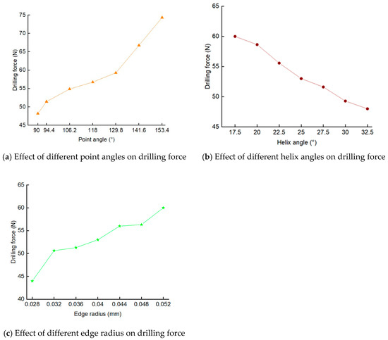
Figure 4.
The influences of bit edge shape parameters on drilling force.
3. Methodology
The experiments aim to verify the difference between the experimental results obtained by finite element simulation and the experimental results to facilitate the follow-up analysis. Three main factors are presented in Table 3. Φ5.0 mm HSS bit in medical operations is used. The drilling speed, feed rate and bit diameter keep constant.

Table 3.
Levels of parameters used in drilling.
3.1. Specimen Details of the Experiments
An in vitro study was conducted on fresh pig femur from an animal slaughterhouse. No animals were harmed or killed during this study. The selection of porcine femur is because its mechanical and thermal properties are similar to those of the human bone. A fresh pig femur without physical injury is selected, and the longitudinal length of the femoral shaft shall be more than 150 mm, the size in radial direction shall be more than 30 mm, and the left and right sides shall not be limited. The soft tissue on the femur shall be cleared [38].
3.2. Experimental Apparatus
The overall experimental setup is shown in Figure 5a. JHBS-1 force sensor and MCK-Z-1 data display are used to monitor drilling force during drilling.
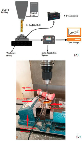
Figure 5.
(a) Schematic diagram of the experimental device and (b) experimental setup.
The porcine femur held in a steel strip has two drilled holes and is screwed to the horizontal surface of the force sensor to ensure that the bone material does not move during drilling and not affect the accuracy of the drilling force; the dynamometer is clamped on a small mobile bench vice and communicated with the computer display via a data line, as shown in Figure 5b.
4. Results and Analysis
4.1. Validation of Simulated Results
Table 4 presents the simulated results, and the data in Table 4 is analyzed through the analysis of variance (ANOVA, Ronald Fisher, UK) to find out the bit parameters which have an important influence on the drilling force. The data analysis details are shown in Table 5.

Table 4.
Orthogonal arrays for three process parameters.

Table 5.
Analysis of variance (ANOVA) of bit parameters influence on drilling force.
From Table 5, it can be seen that under the level of significance of 0.25, the point angle and helix angle have no significance on the drilling force, so it can be considered that they are not the main factors affecting the bone drilling force, and the edge radius has a significant influence on the drilling force.
Figure 6 shows the results of five simulations and experiments. The results show that the relative error between them is 13–21%, which is slightly larger. However, the similar variation trend illustrates that the simulation model can basically reflect the drilling process of pig femur in the experiment and support the subsequent optimization.
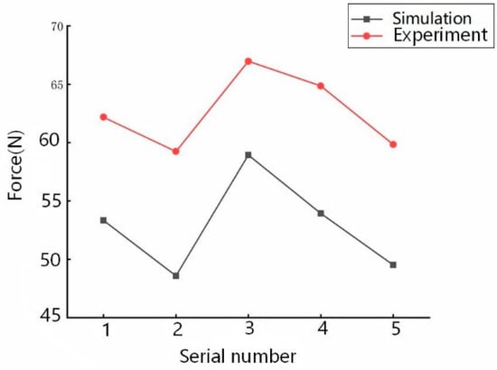
Figure 6.
Contrast diagram.
4.2. Regression Model
The purpose of regression analysis of drilling force is to evaluate the relationship between drilling force and point angle, helix angle as well as edge radius.
ANOVA analyzes the drilling forces obtained in Table 5. First, an analysis of variance was performed on all significant and insignificant items. The models of cutting force are influenced by the parameters of point angle, helix angle and edge radius. Therefore, these models are modified and improved by analyzing the items that greatly influence the drilling force. The empirical regression equation for the relationship between drilling force and bit type is shown in (2):
After the empirical regression equation expression is obtained, the prediction model of the point angle, helix angle and edge radius on drilling force can be fitted by analyzing the multivariate linear regression database function with MATLAB. As seen in Table 6, all regression coefficients are within the confidence interval of regression. The predictive model equation is shown in (3):
where, Φ0 is the point angle, β is the helix angle, r is the edge radius and F is the drilling force.

Table 6.
Regression results of drilling force prediction model.
Table 7 is the statistical scale of the predictive mathematical model, in which R2 is statistics, F statistics and P value. R2 = 0.9503 shows that the model can fit 95% of the experimental data, and if the P value is less than 0.05, the fitting effect is significant.

Table 7.
Model statistic scale.
The residual of the linear regression model of drilling force is shown in Figure 7. It is found that the confidence intervals of 9 residual values are all around the zero point, and the residual ranges are all near the zero point.
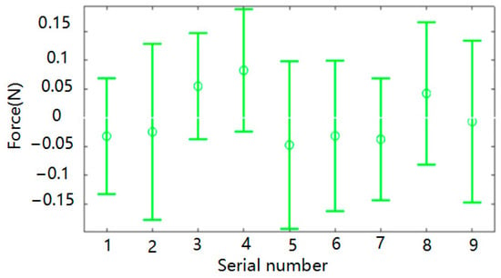
Figure 7.
Residual diagram.
4.3. Particle Swarm Optimization
Particle Swarm Optimization (PSO), proposed by Prof. Kennedy and Prof. Eberhart in 1995, is a stochastic parallel optimization algorithm that is simple and easy to implement. PSO algorithm has been paid much attention since it was introduced. PSO has been widely used in single-objective optimization, constrained optimization, dynamic optimization, multi-objective optimization, and dynamic multi-objective optimization [39].
Particle swarm optimization is used to optimize the structure of the twist drill bit as follows:
- (1)
- Particle swarm initialization
Assuming that the optimal problem is in the D dimension when the initial number of particles is N, the position of each particle can be represented by the D dimension vector and expressed as follows:
Similarly, the velocity of a particle is represented by a D vector:
In the particle swarm, the initial position and velocity of each individual must be random, and the number of groups must be reasonable. Otherwise, the search range will be too extensive, and the calculation will be too large; in this paper, three parameters are used to describe the position and velocity of particles to meet the search requirements. At the same time, it can avoid the position of particles beyond the predetermined range or cause high-speed flight problems. Firstly, the position of a single particle is confirmed according to the selected factor range. Based on the influence range’s size, the particle’s velocity is defined differently. Finally, the equation can realize the initialization of the particle swarm.
- (2)
- Calculation of individual and group fitness values
Particles in the new position will be judged by the size of their fitness function and best if the value is more significant. Each particle updates the extremum of the individual according to the corresponding function value of the current position and compares it with the global extremum.
- (3)
- Update particle velocity and position
In any iteration, the formula is derived from previous individual particles and population extremes. Update self-location and speed:
where, Vi (t) is the velocity of the particle i at the time of t, ω is the inertial weight, Xi (t) is the position of the particle at the time of t, r1, r2 is a random number between (0, 1), c1, c2 is the learning factor, Pbest is the optimal value for an individual, and Gbest is the optimal value for a population.
From the above formula, we can see that the particle renewal rate is affected by the inertia, self-factor and population factor, which represents the speed of the last iteration and the extreme value propensity to individuals and groups, respectively. After each accelerated and positioned update, the region’s size is determined based on the size of the region, and the operation is repeated until it is complete. Based on the above regression model, the minimum cutting force combinations such as point angle, helix angle, and edge radius are obtained. Figure 8 shows the iterative approach of PSO, and we can see that after 25 iterations, its most optimal point has become stable. The final minimum drilling force is 30.31 N, and the corresponding point angle, helix angle, and edge radius of the twist drill are 95°, 35°, and 0.02 mm, respectively. In order to test the accuracy of the PSO algorithm, the numerical simulation experiments are carried out with the above-obtained bit shape parameters, and the maximum drilling force is 29.5 N. The deviation of the optimal solution is 2.75%. The results show that the edge shape parameters obtained by the PSO algorithm can reduce the cutting force to the maximum extent within the range of experimental parameters. Under the original drilling parameters, the drilling force of the swine femur specimen is 53.93, and the cutting force of the new cutting edge can be significantly reduced. Therefore, it is vital to study the influence of bit shape parameters on the drilling force and reduce the drilling force.
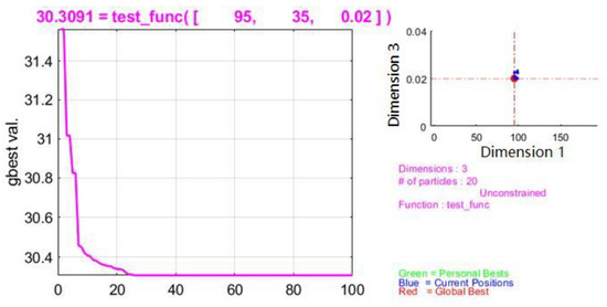
Figure 8.
The iterative process of particle swarm optimization.
Figure 9 shows the regression surface diagram between the cutting force and the point angle, helix angle and the edge radius. From Figure 9a–c, it can be found that the most critical parameter affecting the cutting force is the edge radius, followed by the point angle and finally the helix angle. This is because the edge radius directly participates in the whole drilling process. With the increase in the edge radius, the contact area with material increases, which leads to the increase in drilling force. With the increase in the point angle, the contact area between the flank and the material increases, which also affects the drilling force.
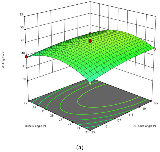
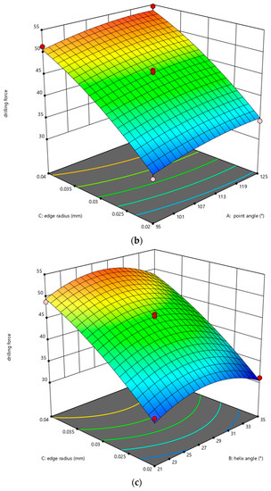
Figure 9.
Influence of bit edge shape parameters on drilling force. (a) Influence of point angle and helix angle on drilling force; (b) Influence of point angle and edge radius on drilling force; (c) Influence of edge radius and helix angle on drilling force.
5. Discussion
The previous mostly related studies are presented in Table 8. It can be seen from Table 8 that there are mainly two types of research contents; one is about drill bit parameters, and the other is about with or without coolant. For the former case, in addition to the drilling speed and feed rate, literature [9,10,14] studied one parameter of the drill bit, i.e., the point angle, and literature [28] studied two parameters (point angle and helix angle); and for the latter, literature [40,41,42,43] focused on the effect of the coolant on drilling temperature, thermal damage or drilling quality. As for this work, there are three novelties: (1) more parameters (including point angle, helix angle and edge radius) of the drill bit edge shape are investigated on the premise of the predetermined rotation speed and feed rate. (2) The order of the influence of drill bit shape parameters on the drilling force is obtained: the edge radius is the largest, the point angle is the second, and the helix angle is the smallest. (3) The optimum combination of bit structure is obtained by using particle swarm optimization algorithm. Therefore, this work demonstrates that the number of main bit edge shape parameters affecting the drilling force are more than one or two, and their influence order on drilling force are different. Furthermore, the optimized matching of bit edge shape parameters using optimization algorithm is obtained. Hence, this paper provides a theoretical basis for selecting the appropriate drill bit shape in the design of drill and contributes to the further study of the bone drilling.

Table 8.
Comparison between previous mostly related studies and this work.
6. Conclusions
Most researchers studied the drilling parameters or one or two parameters of the cutting edge. To obtain the best drilling parameters and drill bit edge shape parameters, this work further studies the influence of point angle, helix angle and edge radius on drilling forces in detail and draws the following conclusions:
When the rotary speed is 1100 r/min and the diameter of the drill is 5 mm, the drilling force at the feed speeds of 0.03 mm/r, 0.07 mm/r, 0.11 mm/r and 0.15 mm/r is analyzed, respectively. It is found that the drilling force is the lowest at the feed speed of 0.03 mm/r, and its value is about 40 N.
This work found that the variation trend of drilling force is consistent with the experiment, and the relative error is 13–21%, which is slightly larger. However, the similar variation trend illustrates that the simulation model can basically reflect the drilling process in the experiments.
Through the analysis of drill bit shape parameters, it is found that edge radius has the most significant influence on drilling force, followed by point angle and then helix angle. The prediction model of the relationship between the bit shape parameters and drilling force is established through regression analysis. The model can fit 95% of the experimental data, and the fitting effect is significant. The model is optimized by adopting particle swarm optimization algorithm, and the minimum drilling force is 30.31 N. The optimum drill bit shape parameter combination is 95° in point angle, 35° in helix angle, and 0.02 mm in edge radius.
Author Contributions
Conceptualization, X.C.; methodology, T.H. and X.C.; software, T.H.; validation, T.H.; formal analysis, T.H.; investigation, T.H.; resources, T.H; data curation, T.H. and X.G.; writing—original draft preparation, T.H.; writing—review and editing, M.D.; visualization, T.H.; supervision, M.D.; project administration, M.D.; funding acquisition, M.D. All authors have read and agreed to the published version of the manuscript.
Funding
This research was supported by the National Natural Science Foundation of China (grant Number 61562055).
Institutional Review Board Statement
Attachment view.
Informed Consent Statement
Not applicable.
Data Availability Statement
Data sharing not applicable.
Conflicts of Interest
The authors declare no conflict of interest.
References
- Pandey, R.K.; Panda, S.S. Evaluation of delamination in drilling of bone. Med. Eng. Phys. 2015, 37, 657–664. [Google Scholar] [CrossRef]
- Kasiri, S.; Reilly, G.; Taylor, D. Wedge Indentation Fracture of Cortical Bone: Experimental Data and Predictions. J. Biomech. Eng. 2010, 132, 81009. [Google Scholar] [CrossRef]
- Bassi, J.L.; Pankaj, M.; Navdeep, S. A Technique for Removal of Broken Cannulated Drill Bit: Bassi’s Method. J. Orthop. Trauma 2008, 22, 56–58. [Google Scholar] [CrossRef]
- Bachus, K.N.; Rondina, M.T.; Hutchinson, D.T. The effects of drilling force on cortical temperatures and their duration: An in vitro study. Med. Eng. Phys. 2000, 22, 685–691. [Google Scholar] [CrossRef]
- Paulsson, J.; Stig, J.C.; Olsson, O. Comparison and analysis of reoperations in two different treatment protocols for trochanteric hip fractures—Postoperative technical complications with dynamic hip screw, intramedullary nail and Medoff sliding plate. BMC Musculoskel. Dis. 2017, 18, 364. [Google Scholar] [CrossRef]
- Wachtl, S.W.; Gautier, E.; Jakob, R.P. Low reoperation rate with the Medoff sliding plate: 1 technical failure in 63 trochanteric hip fractures. Acta Orthop. Scand. 2001, 72, 141–145. [Google Scholar] [CrossRef]
- Allan, W.; Williams, E.D.; Kerawala, C.J. Effects of repeated drill use on temperature of bone during preparation for osteosynthesis self-tapping screws. Brit. J. Oral Maxillofac. Surg. 2005, 43, 314–319. [Google Scholar] [CrossRef]
- Itoh, S.; Ito, Y.; Shikita, T. Basic Study on Bone Cutting Forces for Developing Surgical Instruments. Bull. JSME 2008, 26, 2295–2301. [Google Scholar] [CrossRef][Green Version]
- Augustin, G.; Davila, S.; Mihoci, K.; Udiljak, T.; Vedrina, D.S.; Antabak, A. Thermal osteonecrosis and bone drilling parameters revisited. Arch. Orthop. Trauma Surg. 2008, 128, 71–77. [Google Scholar] [CrossRef]
- Udiljak, T.; Ciglar, D.; Škorić, S. Investigation into bone drilling and thermal bone necrosis. Adv. Prod. Eng. Manag. 2007, 2, 103–112. [Google Scholar]
- Lee, J.; Rabin, Y.; Ozdoganlar, O.B. A new thermal model for bone drilling with applications to orthopaedic surgery. Med. Eng. Phys. 2011, 33, 1234–1244. [Google Scholar] [CrossRef] [PubMed]
- Karmani, S.; Lam, F. The design and function of surgical drills and K-wires. Curr. Orthop. 2004, 18, 484–490. [Google Scholar] [CrossRef]
- Lughmani, W.A.; Bouazza-Marouf, K.; Ashcroft, I. Drilling in cortical bone: A finite element model and experimental investigations. J. Mech. Behav. Biomed. 2015, 42, 32–42. [Google Scholar] [CrossRef]
- Karaca, F.; Aksakal, B.; Kom, M. Influence of orthopaedic drilling parameters on temperature and histopathology of bovine tibia: An in vitro study. Med. Eng. Phys. 2011, 33, 1221–1227. [Google Scholar] [CrossRef] [PubMed]
- Pandey, R.K. Drilling of bone: A comprehensive review. J. Clin. Orthop. Trauma 2013, 4, 15–30. [Google Scholar] [CrossRef]
- Wang, Y.; Cao, M.; Zhao, X.; Zhu, G.; McClean, C.; Zhao, Y.; Fan, Y. Experimental investigations and finite element simulation of cutting heat in vibrational and conventional drilling of cortical bone. Med. Eng. Phys. 2014, 36, 1408–1415. [Google Scholar] [CrossRef] [PubMed]
- Sui, J.; Sugita, N.; Ishii, K.; Harada, K.; Mitsuishi, M. Mechanistic modeling of bone-drilling process with experimental validation. J. Mater. Processing Tech. 2014, 214, 1018–1026. [Google Scholar] [CrossRef]
- Soriano, J.; Iriarte, L.M.; Eguren, J.A.; Aristimuño, P.; Garay, A.; Arrazola, P.J. Effects of rotational speed and feed rate on temperature rise, feed force and cutting torque when drilling bovine cortical bone. In AIP Conference Proceedings; American Institute of Physics: College Park, MD, USA, 2012. [Google Scholar]
- Hillery, M.T.; Shuaib, I. Temperature effects in the drilling of human and bovine bone. J. Mater. Processing Tech. 1999, 92–93, 302–308. [Google Scholar] [CrossRef]
- Saha, S.; Pal, S.; Albright, J.A. Surgical drilling: Design and performance of an improved drill. J. Biomech. Eng. 1982, 104, 245. [Google Scholar] [CrossRef]
- Moufki, A.; Molinari, A. A new thermomechanical model of cutting applied to turning operations. Part II. Parametric study. Int. J. Mach. Tools Manuf. 2005, 45, 181–193. [Google Scholar] [CrossRef]
- Endres, W.J.; Kountanya, R.K. The Effects of Corner Radius and Edge Radius on Tool Flank Wear. J. Manuf. Processes 2002, 4, 89–96. [Google Scholar] [CrossRef]
- Chou, Y.K.; Hui, S. Tool nose radius effects on finish hard turning. J. Mater. Processing Tech. 2004, 148, 259–268. [Google Scholar] [CrossRef]
- Horváth, R. A New Model for Fine Turning Forces. Acta Polytech. Hung. 2015, 12, 109–128. [Google Scholar]
- Tang, L.; Cheng, Z.; Huang, J.; Gao, C.; Chang, W. Empirical models for cutting forces in finish dry hard turning of hardened tool steel at different hardness levels. Int. J. Adv. Manuf. Tech. 2015, 76, 691–703. [Google Scholar] [CrossRef]
- Kishawy, H.A. An experimental evaluation of cutting temperatures during high speed machining of hardened D2 tool steel. Mach. Sci. Technol. 2002, 6, 67–79. [Google Scholar] [CrossRef]
- Chen, J.; Zhang, H.; Liu, P.; Li, Y.; Liu, X.; Li, G.; Wong, P.K.; An, T.; Zhao, H. Cross-linked ZnIn2S4/rGO composite photocatalyst for sunlight-driven photocatalytic degradation of 4-nitrophenol. Appl. Catal. B Environ. 2015, 168–169, 266–273. [Google Scholar] [CrossRef]
- Lee, J.E.; Ozdoganlar, O.B.; Rabin, Y. An experimental investigation on thermal exposure during bone drilling. Med. Eng. Phys. 2012, 34, 1510–1520. [Google Scholar] [CrossRef]
- Wang, W.; Shi, Y.; Yang, N.; Yuan, X. Experimental analysis of drilling process in cortical bone. Med. Eng. Phys. 2014, 36, 261–266. [Google Scholar] [CrossRef]
- Davidson, S.; James, D.F. Drilling in bone: Modeling heat generation and temperature distribution. J. Biomech. Eng. 2003, 125, 305–314. [Google Scholar] [CrossRef]
- Santiuste, C.; Rodríguez-Millán, M.; Giner, E.; Miguélez, H. The influence of anisotropy in numerical modeling of orthogonal cutting of cortical bone. Compos. Struct. 2014, 116, 423–431. [Google Scholar] [CrossRef]
- Alam, K.; Mitrofanov, A.V.; Silberschmidt, V.V. Thermal analysis of orthogonal cutting of cortical bone using finite element simulations. Int. J. Exp. Comput. Biomech. 2010, 1, 236–251. [Google Scholar] [CrossRef]
- Bagci, E.; Ozcelik, B. Investigation of the effect of drilling conditions on the twist drill temperature during step-by-step and continuous dry drilling. Mater. Des. 2006, 27, 446–454. [Google Scholar] [CrossRef]
- Soriano, J.; Garay, A.; Ishii, K.; Sugita, N.; Arrazola, P.J.; Mitsuishi, M. A New Surgical Drill Bit Concept for Bone Drilling Operations. Mater. Manuf. Processes 2013, 28, 1065–1070. [Google Scholar] [CrossRef]
- Shakouri, E.; Sadeghi, M.H.; Maerefat, M.; Shajari, S. Experimental and analytical investigation of the thermal necrosis in high-speed drilling of bone. Proc. Inst. Mech. Eng. Part H J. Eng. Med. 2014, 228, 330–341. [Google Scholar] [CrossRef] [PubMed]
- Basiaga, M.; Paszenda, Z.; Szewczenko, J.; Kaczmarek, M. Influence of surgical drills wear on thermal process generated in bones. Acta Bioeng. Biomech. Wroc. Univ. Technol. 2013, 15, 19–23. [Google Scholar]
- Abdellaoui, L.; Khlifi, H.; Sai, W.B.; Hamdi, H. Tool nose radius effects in turning process. Mach. Sci. Technol. 2020, 25, 1–30. [Google Scholar] [CrossRef]
- Li, C.; Bai, Y.; Kong, X.; Chen, L.; Li, J.; Du, Z.; Le, X.; Tang, L. Testing of drilling feed force on fresh porcine femur. J. Med. Biomech. 2014, 29, 560–566. [Google Scholar]
- Eberhart, R.; Kennedy, J. A new optimizer using particle swarm theory. In Proceedings of the Sixth International Symposium on Micro Machine & Human Science (MHS’95), Nagoya, Japan, 4–6 October 1995. [Google Scholar]
- Gholampour, S.; Hassanalideh, H.H.; Gholampour, M.; Frim, D. Thermal and physical damage in skull base drilling using gas cooling modes: FEM simulation and experimental evaluation. Comput. Meth. Prog. Biomed. 2021, 212, 106463. [Google Scholar] [CrossRef]
- Deh, H.; Gholampour, S. Finding the optimal drill bit material and proper drilling condition for utilization in the programming of robot-assisted drilling of bone. CIRP J. Manuf. Sci. Technol. 2020, 31, 34–47. [Google Scholar]
- Gholampour, S.; Droessler, J.; Frim, D. The role of operating variables in improving the performance of skull base grinding. Neurosurg. Rev. 2022, 45, 2431–2440. [Google Scholar] [CrossRef]
- Linlin, X.U. Drilling Force and Temperature of Bone under Dry and Physiological Drilling Conditions. Chin. J. Mech. Eng. 2014, 27, 1240–1248. [Google Scholar]
Publisher’s Note: MDPI stays neutral with regard to jurisdictional claims in published maps and institutional affiliations. |
© 2022 by the authors. Licensee MDPI, Basel, Switzerland. This article is an open access article distributed under the terms and conditions of the Creative Commons Attribution (CC BY) license (https://creativecommons.org/licenses/by/4.0/).