1. Introduction
Drone applications are widely studied in various industrial fields due to the potential it brings by overcoming the limitation of road transportation. Their ability to view large areas at a low cost from altitude provides new viewing aspects and new data acquisition ability (or existing data can be sourced at a large scale at a lower cost) to make decisions and manage operations more effectively [
1]. Moreover, we are currently witnessing the potential of supply-delivery (e.g., Emergency medical support and courier delivery) applications in urban areas [
2]. However, civil confidence in urban drone operations is still questionable, as injuries and property damage resulting from drone flights over populated areas are not unusual [
3,
4]. Numerous statistics report a vast increase in drone-involved incidents, especially in urban areas. According to recent research in the UK, the number of reported drone-caused incidents increased by 1000% from 2014 to 2017 [
5]. Therefore, commercial and policymaking efforts are turning to contemplating this future and how airborne drones may need control in such uses [
1]. The current drone-control technology seems not sufficient to satisfy universal concerns on drone safety. In order to meet the rising demands of commercial drone industries, a reliable double-safe drone-control method is necessary. We consider our proposed method to be a solution to this matter.
2. Background
Many studies argue that the dominating drone-control method, PID (Proportional Integral Derivative) control, offers the simplest and yet most efficient solution to many real-world control problems [
6,
7,
8]. However, some reviews point out the limitations of the current dominating technology. Smyczynski [
9] mentioned that using PID regulators for the following platform (AR Drone) was successful only with a movement speed of less than 5 km/h. However, to achieve satisfactory results with higher speed, other types of regulators should be tested [
9]. We considered this issue was due to the feedback architecture and the low-level approach it takes. Instability is the disadvantage of feedback. When using feedback there is always a risk that the closed-loop system will become unstable [
10]. And moreover, control methods that rely on GPS (global positioning system) data [
11,
12,
13] cannot avoid the sensor data error problem [
3].
Recent research has claimed new methods to handle the instability of drone control with various approaches [
14]. Some of them improved the existing algorithm, whereas others took a higher-level approach by implementing mission-control layers on top of PID controllers. Numerous studies introduced fault-tolerant control mechanisms (e.g., [
15,
16,
17,
18,
19,
20,
21]). Heredia [
17] and Qin [
19] introduced sensor-failure detection methods. These approaches focus on providing a fault-tolerant sensor data filter and reducing sensor errors during computation. However, it was not possible to overcome all types and degrees of sensor failures in these studies. Furthermore, they only apply to internal fails. Our approach, on the other hand, is capable of detecting both external and internal fails and emergencies, and is independent of the type and degree of failure. Previous approaches did not take situation awareness into account and lacked the ability to perceive and respond to situations outside of normal conditions.
Our novel method takes a strategic-level approach to meet the requirements of modern drone applications. Unlike PID-based control methods, our methodology does not involve the low-level control loop. However, it takes place in the detection and diagnosis of abnormal situations and operates as a second-hand safety insurance. This is achieved by implementing temporal scoping, checking the interval of time spent maneuvering from one location to another. By operating in conjunction with PID-based control algorithms, we should be able to provide a much wider range of flight-safety insurance coverage and maintain the preservation of cutting-edge robust control technology at the same time.
3. Proposed Methodology
Our proposal is an event-based emergency detection method using the temporal (time) scope as a diagnosis method. The main idea of the time-window is to expect the drone to arrive at certain waypoints in a definite time-window [
22]. The goal of this is to make sure there is no internal or external failure that affected the mission in any means by assuming that if the drone does not make it in time there is an issue.
Many unexpected emergency conditions could possibly occur during autonomous drone missions, which are not easy to detect without strategic control methods. We designed our control method to operate in conjunction with existing control methods and handle abnormal situations, whereas the basic functionalities of a drone such as sensing and controlling are done with PID-based low-level control algorithms.
We defined a safe drone framework to handle unexpected situations with our event-based intelligent controller operating in conjunction on a high-level with a mission controller in the middle and a PID controller at a low-level as shown in
Figure 1 [
23]. The event-based intelligent controller uses the time-window for abnormality detection while the two other controllers work on the drone maneuver controls. The mission controller is a mid-level controller for path planning and navigating designed based on other studies (e.g., [
24,
25,
26,
27,
28]).
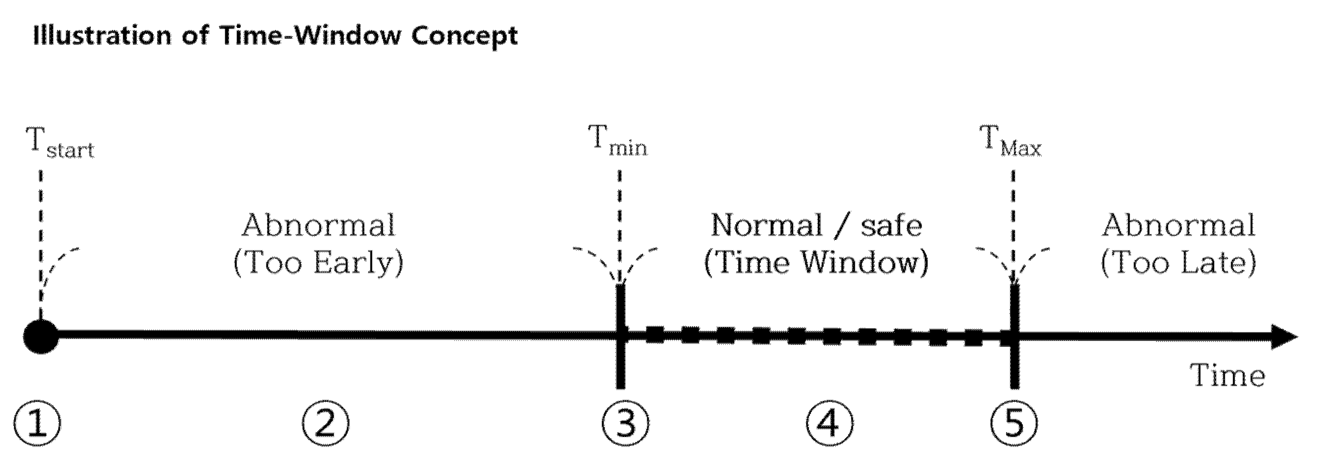
A time-window is a temporal scope with a minimum-acceptance time and maximum-acceptance time. The significance of this approach is that it is capable of handling emergency situations even without diagnosing the specific cause and situations. The individual time values (Tmax-intitial, Tmin-intitial) for each waypoint interval should be calculated before flight operations.
During the flight, our controller will retrieve the current time and the state of the drone. The state of the drone includes information on which waypoint interval the drone is passing currently. By calculating the Tstart (the actual time the drone left the last waypoint) and the values of Tmax and Tmin, the drone can determine the finalized time-window Twindow. The calculation of the variables and the time-window is detailed below with definitions and Equations (1)–(4).
Let Texp-int be the expected interval time from one waypoint to another.
Let α be the rate of maximum late arrival acceptance, and let β be the rate of maximum early arrival acceptance.
Then we defined the maximum and minimum acceptable interval time as below.
Let Tstart be the actual time the drone left the previous waypoint.
Then we defined the maximum and minimum acceptable time as below.
where T
min < T
window < T
maxLet Twindow be the acceptable time-window range for the interval maneuver.
Texp-int from the above equations is a statistic average value of a time interval from one waypoint to another. It is calculated by a function that takes the distance between two specific waypoints. In our case, we applied environmental wind in two opposing directions with the amount of maximum wind speed our drone can handle.
3.1. System Architecture
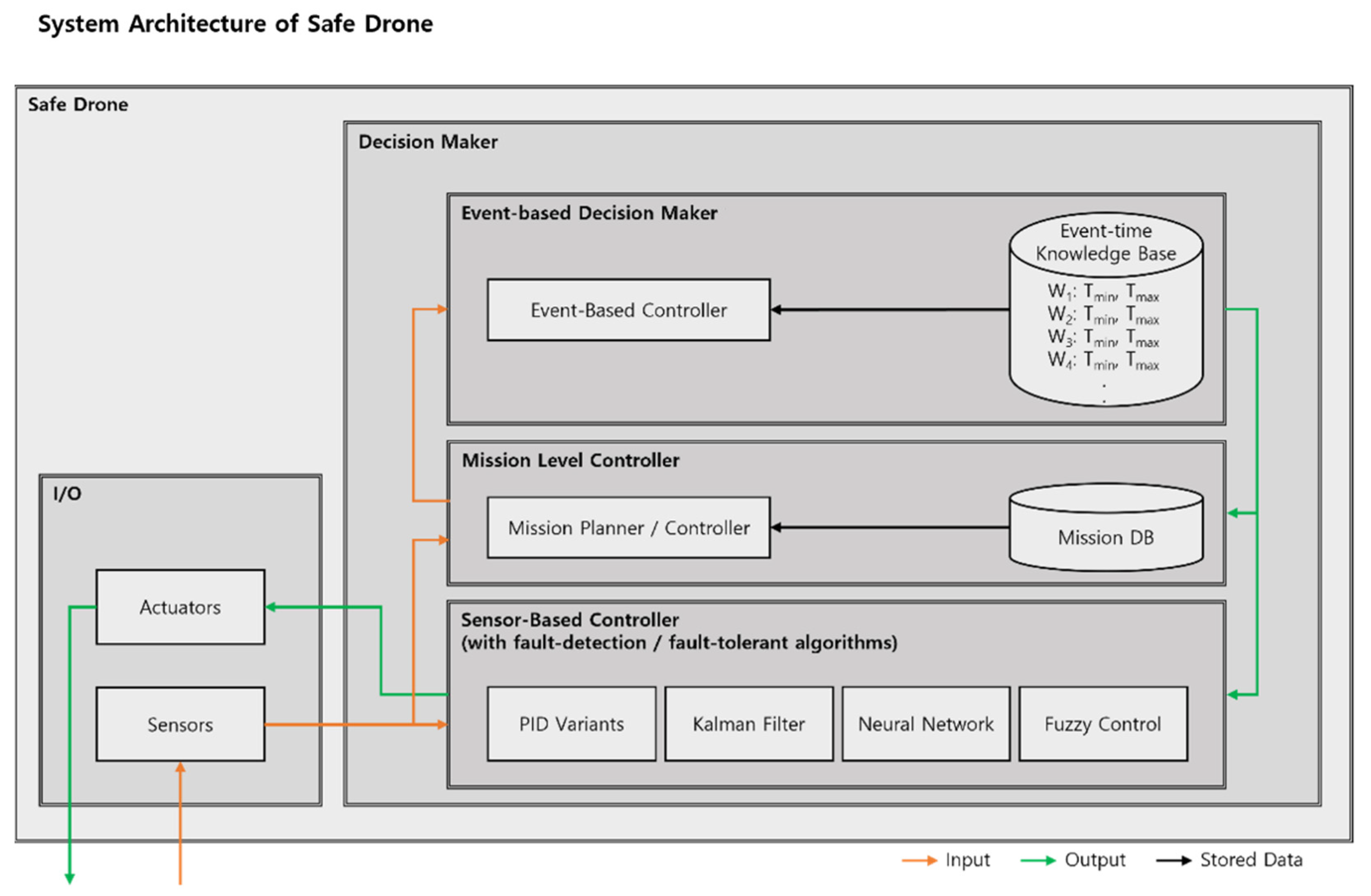
Firstly, in terms of implementing our time-window (temporal scope) to a drone, we designed an event-based controller that cooperates with other controllers, as shown in
Figure 2. We assumed that the overall drone system includes a group of input sensors, a group of actuators, a sensor-based low-level control loop, and a mission-level controller. By adding our event-based controller (decision-maker) to the drone system mentioned above, we were able to define a safe drone.
The expected time-window data for each waypoint interval should be pre-defined before flight operations and stored in the knowledge base, inside the event-based controller. We attempted to illustrate a safe drone system with our event-based controller mounted on top of a typical drone system and combining both into a decision-making controller.
The event-based controller will receive processed sensor data such as time and location, refined by the existing controller. It will then process the emergency-detection algorithm using both the delivered sensor data and its pre-defined time-window data, stored inside its knowledge base. If needed, the event-based controller can command the PID-based controller to proceed with an emergency landing.
3.2. Event-Based Control Mechanism
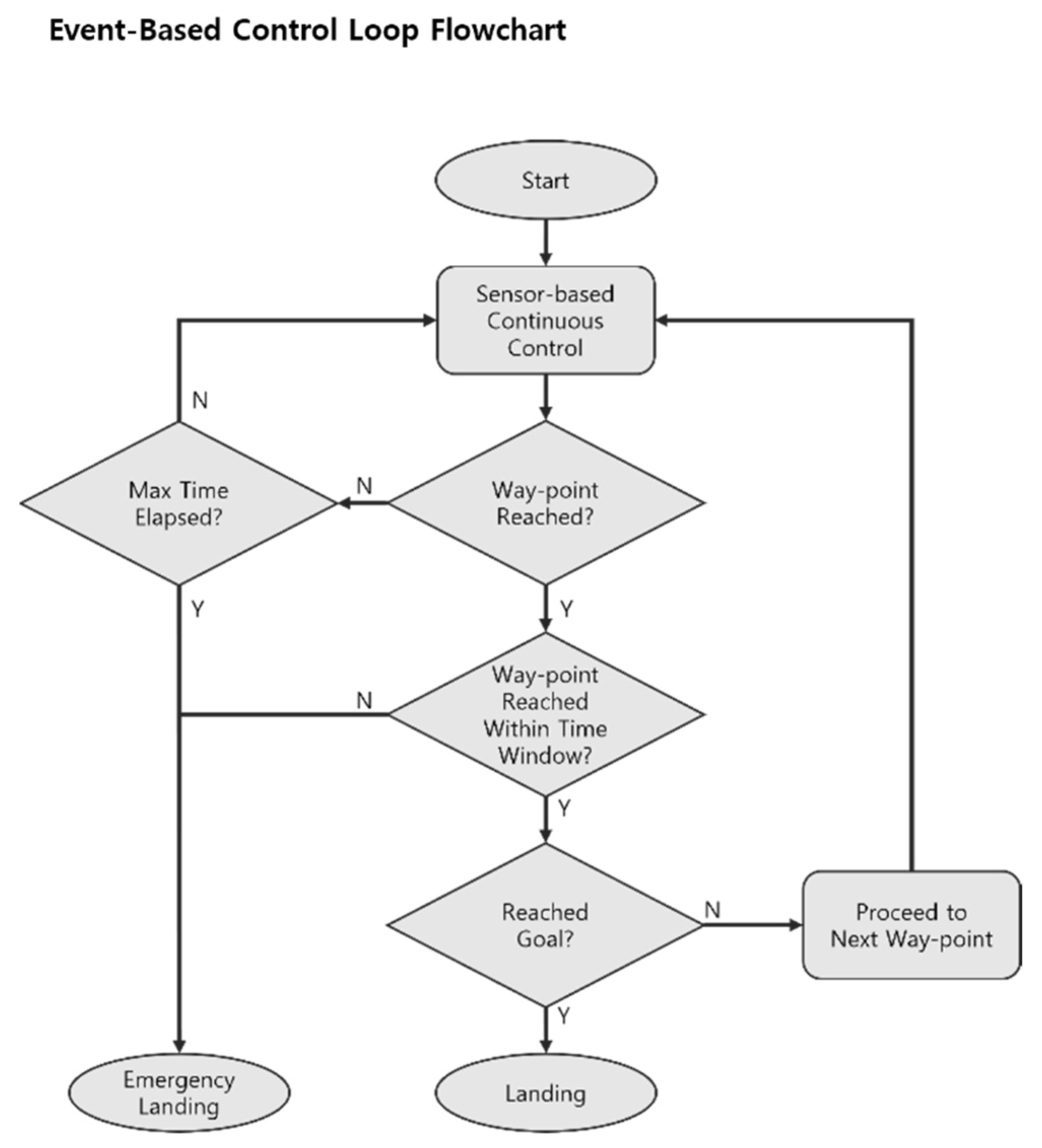
To explain the time-window mechanism in a logical order, even before the event-based emergency-detection system operates, the integrated low-level sensor-based controller will accept sensor data inputs and perform an internal control loop. After the low-level controller involvement, the event-based controller would diagnose emergencies based on time-window mechanisms, as shown in
Figure 3.
If the drone has reached the waypoint, the event-based controller will check whether the arrival time is in-bound of the pre-designated time-window. However, during the interval, the controller would simultaneously check whether the T
max (maximum acceptable time) was exceeded. If the time is exceeded without arriving at the waypoint, it will diagnose an emergency and command the drone to perform an emergency landing. If the arrival time is earlier than the T
min (minimum acceptable time), the controller will command the drone to perform an emergency landing as well. In other cases where the drone has arrived within the time-window, the controller will either allow the drone to proceed to the next waypoint or perform the final landing procedure, as shown in
Figure 4.
As a result, our event-based controller would be able to detect both early arrivals and late arrivals. By restricting the drone’s maneuvering time interval, we expect to provide a strict standard for drone controls and further ensure fail-safe missions.
The theoretically ideal implementation of our event-based controller is to only operate in a discrete manner based on events such as waypoint arrivals and exceeding time-windows. However, for the practicality of the algorithm, we recommend applying waypoints at narrow intervals to increase the diagnosing cycles and improve the calculation and control accuracy.
4. Case Study
We attempted to test and verify our proposed method in simulation environments to see how well it detects emergency situations. We created a custom 3D simulation environment dedicated to testing our proposed system using AirSim [
29] and Unreal Engine [
30]. We utilized the physics engine and various built-in functionalities in order to implement a full dynamic model of a drone inside our simulator.
4.1. Simulation Environment and Settings
To further explain the details of the implementation of our proposed method inside our simulator, the PID control loop operated at a frequency of 10 Hz, which means the sensor data processing and position prediction was conducted every 0.1 s. The physical simulation functionalities provided by AirSim [
29] and Unreal Engine [
30] were utilized to illustrate randomized noise in terms of drone control outputs with motors. On the other hand, we implemented a custom noise system to sensor measurements. Finally, we designed our event-based controller to perform regular evaluations at a frequency of 2 Hz and perform event-based emergency diagnosis at each waypoint arrival event.
We attempted to simulate several common emergency situations that a drone might encounter in the real world. We considered several possible events, such as collisions (due to deviation and unexpected sudden collisions), system failures (motor, blade, electronics, etc..), sensor malfunctions, and strong winds. In particular, we conducted experiments on and studied three cases: normal case, extreme wind condition, and air collision. We tried to compare the above cases under the terms of the time-window concept. These cases are difficult to detect or respond to with existing control methods, so the effectiveness of our proposed control method should be shown clearly.
Regarding the approach of our system, verifying whether a drone is in a normal state requires estimating the expected time-window before the actual flight mission. The very first step is to define the physical specs of the drone. In our case, we defined the drone as a quadcopter with a wheelbase of 1.13 m, a weight of 3.8 kg, a maximum wind-resistant speed of 6.7 m/s, and a desired flight speed of 5 m/s.
Next, we defined our mission to be a straight-line path traversal starting from way-point A and proceeding through the mission in alphabetical order as A → b → c → d → e → F. After the mission was set, we conducted experiments to configure the equations and variables required for time-window calculations. In order to calculate the time-window for each waypoint, we attempted to average out the amount of time the drone spends while moving various distances. After conducting over 1000 trials, we were able to get the data of expected acceleration speed and ascent speed. We not only tested cruise, acceleration, and de-acceleration conditions but also took various wind conditions in the count. After getting the data, we were able to plot equations for the drone to use during the mission.
4.2. Normal Case
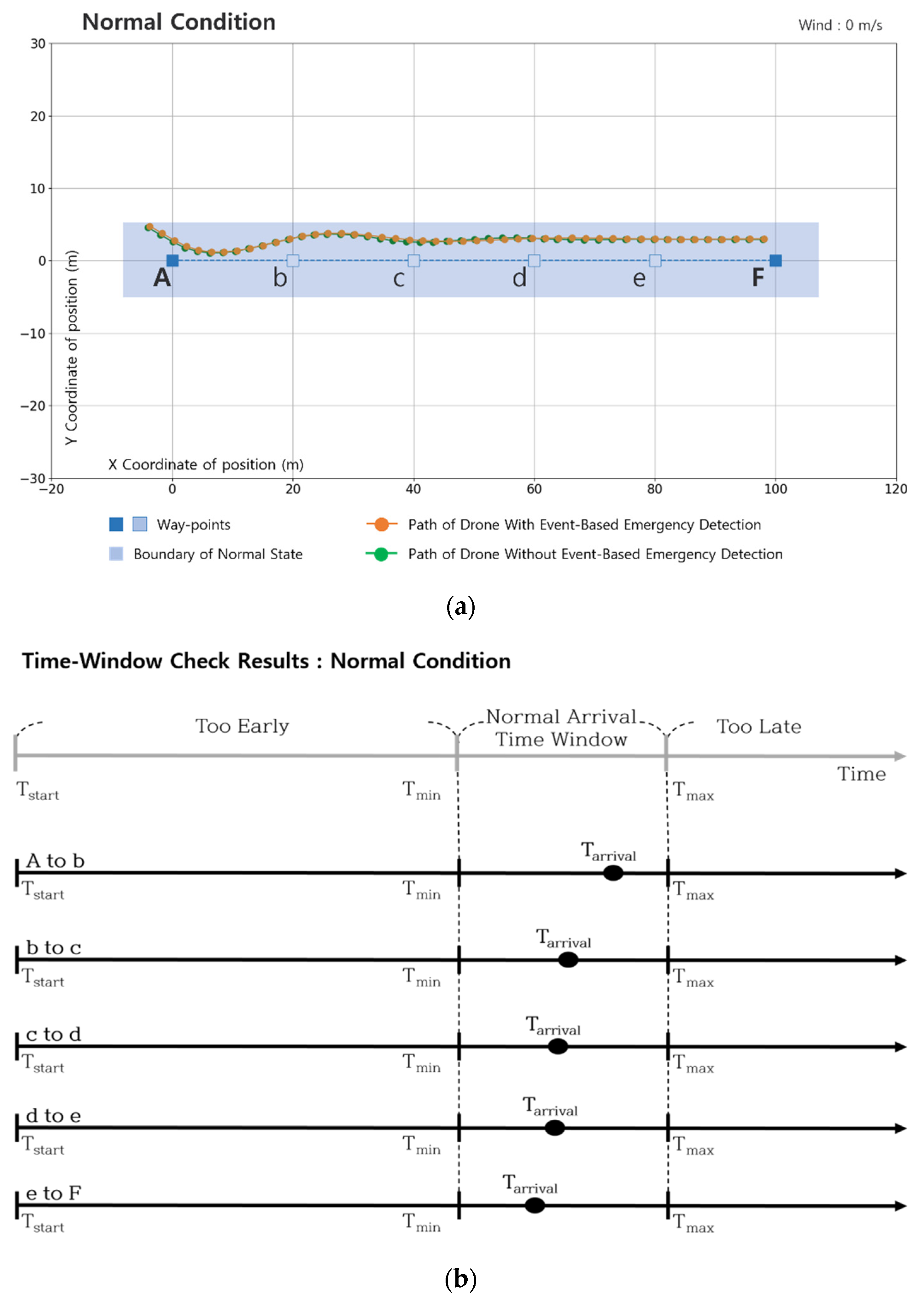
The first case is a normal condition where no emergency event occurs to the drone. This case is a control group for future comparison with other cases.
Figure 5a demonstrates the drone’s movement data during a mission in the simulation environment. It is in a form of a graph, plotted with sequential 2D locations (x, y) of the drone. As shown below, the drone followed the path well and did not detect any type of emergency. In
Figure 5b, we can observe that the drone made it within the boundaries of normal arrival time on every waypoint arrival. Further in
Table 1, the actual numerical time data including T
start, T
min, T
max, and the actual arrival time T
arrival is displayed.
By analyzing the normal case, we were able to partially validate the concept we are introducing and get an idea of the trend of the result data we can expect from the simulator. Especially from the time-window check results, the Tarrival value showed a decreasing pattern, which was due to the drone approaching closer to the desired speed over time. In addition, we gained confidence on the length of the time-window scope we implemented, which was one second. This allowed a foundation to be established for further experiments with different cases.
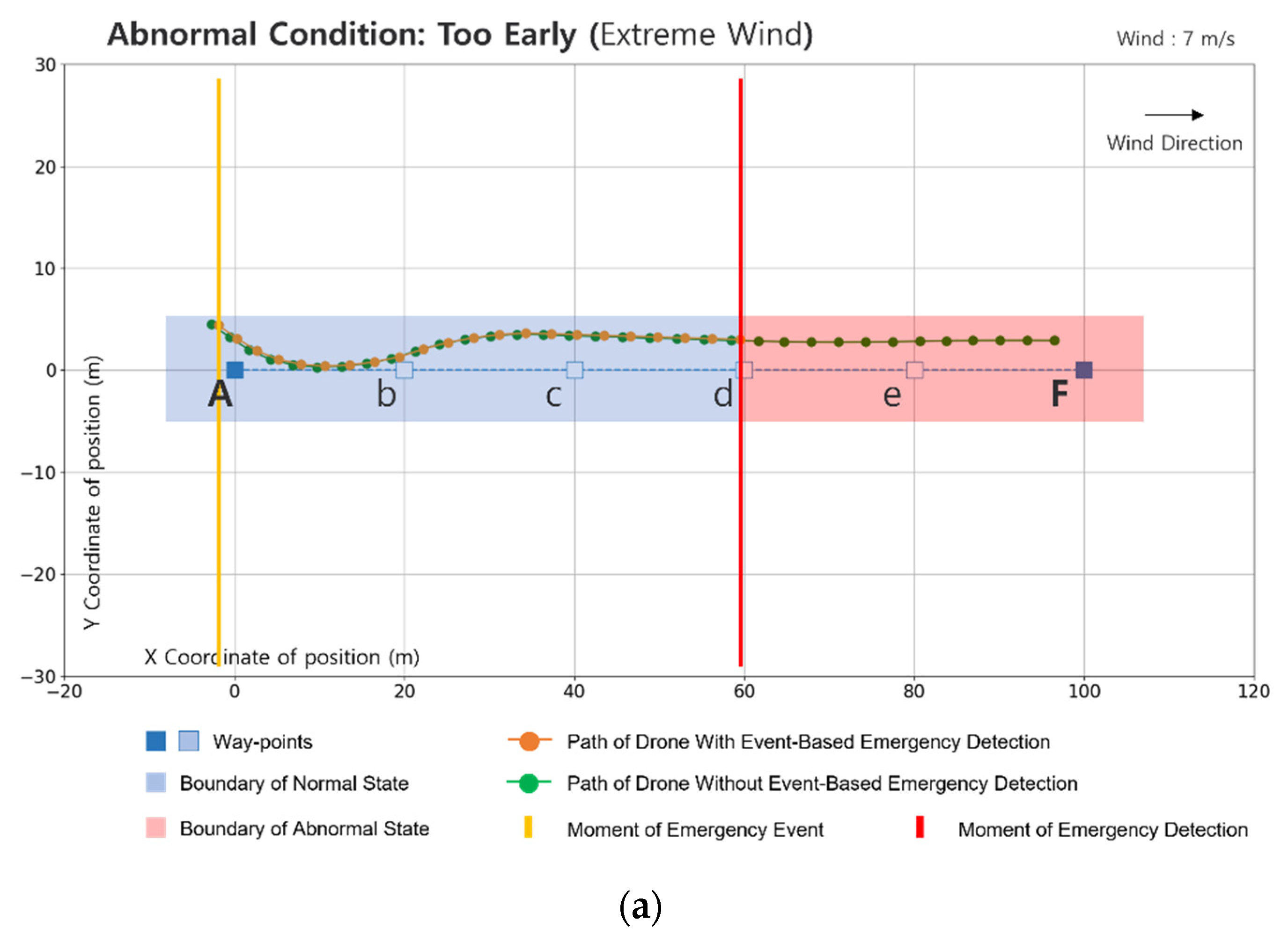
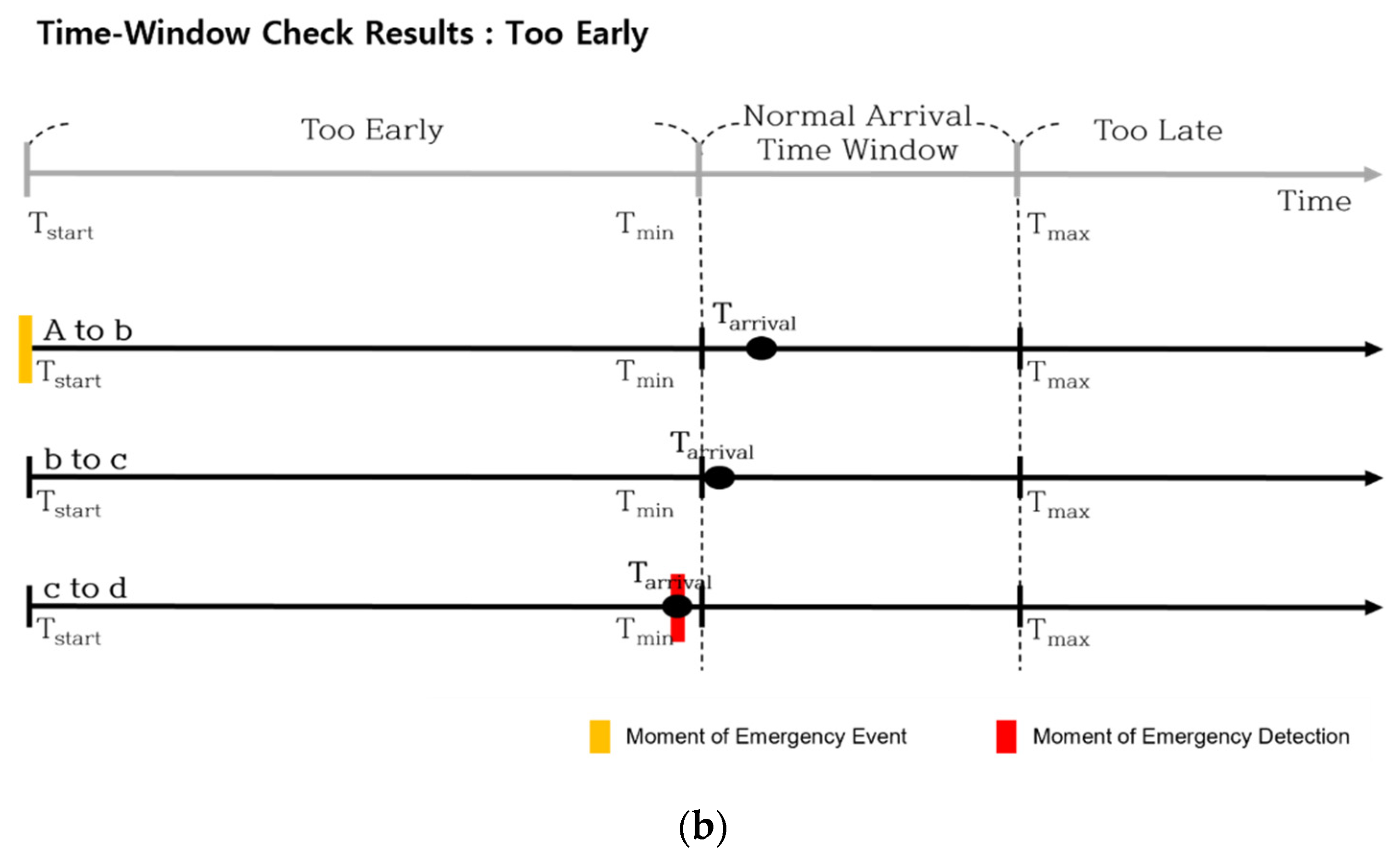
4.3. Abnormal Case: Too Early (Extreme Wind)
The next case is an extreme wind condition. We set the wind speed in this case to 7.0 m/s, which is more than the drone can normally handle. This speed limit is about 5.0 m/s, and is an assumption based on the drone specs and a considerable recommendation for real-world applications.
Figure 6a demonstrates how the drone maneuvers during extreme wind conditions. Since the wind was heading parallel to the drone’s direction, we can observe that the drone was moving faster than expected. After a few waypoints, our event-based controller was able to detect the emergency. As shown in
Figure 6b, when the drone missed the time window during the path from c to d, the drone detected a time-window out of bounds and called for an emergency landing. The red mark points to the moment of detection. Further in
Table 2, the actual numerical time data including T
start, T
min, T
max, and the actual arrival time T
arrival is displayed.
The strong tailwind that exceeded the drone’s capability of control forced the drone to maneuver faster than expected. Even from the first waypoint, the drone nearly made it within the normal arrival time-window. It might be controversial to consider tailwind an abnormal situation, but if the drone is not to move in a straight line, there is a chance of it possibly crashing into obstacles in urban surroundings. This case study proved the capability of our event-based controllers’ ability to handle hard-to-detect abnormal situations.
4.4. Abnormal Case: Too Late (Air Collision)
The next case is the collision encounter simulation. We made the drone get hit by an unknown flying object at waypoint C and examined the control method’s response to the incident, as shown in
Figure 7a. The drone was not able to arrive at waypoint c, meaning it would either call for an emergency landing or deploy a parachute right after the interval time exceeded the max out-of-bounds time-window. In
Figure 7b, the moment of the actual emergency occurrence is marked with a yellow line, whereas the moment of emergency detection is marked with a red line. The moment of emergency detection describes the split moment where the event-based controller diagnose an emergency. Further in
Table 3, the actual numerical time data including T
start, T
min, T
max, and the actual arrival time T
arrival is displayed.
In-air collision is a very dangerous situation for the drone. The initial collision could possibly lead to secondary collisions if it is not handled immediately. The 2D log shows the exact situation. In this particular case, the collision resulted in a failure in the drone’s airframe and caused an out-of-control situation, which is critical in urban areas. However, the event-based controller detected the abnormality within approximately 5 s and proceeded with an emergency landing with the aid of a parachute. Even though collisions are relatively easy to detect, we proved that our method is also able to ensure the diagnosing and handling of collision situations.
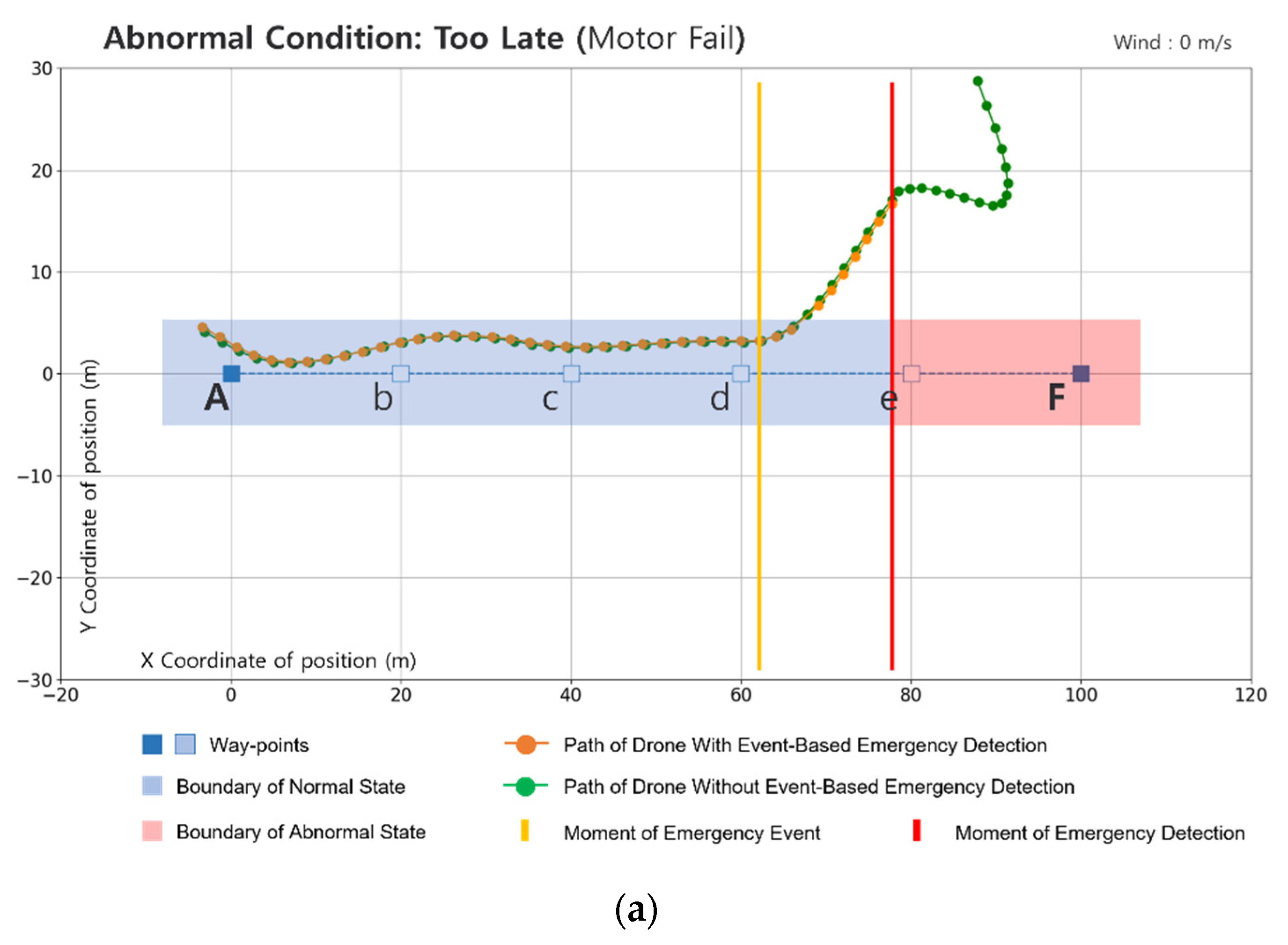
4.5. Abnormal Case: Too Late (Motor Fail)
For the last case we simulated a failure in one of the drone’s four motors. Motor failure could be caused by many reasons in real world situations, and is one of the most catastrophic events, since the drone completely loses control. We let one of the motors fail completely right after the drone passed waypoint d and analyzed the response of our event-based controller, as shown in
Figure 8a. The drone was not able to arrive at the next waypoint and our controller detected the time-window being exceeded.
Figure 8b and
Table 4 show more detailed analysis and data about the case.
Just like air collisions, motor failures are dangerous. Sometimes collisions can cause motor failures as a secondary effect. The 2D log from
Figure 8a resulted in a somewhat similar situation as the one in
Figure 7a. The drone totally lost its control and drifted far away from the safe boundaries. Luckily, as in the previous case, the event-based controller was able to detect the abnormality 5.5 s after the moment of incident. Detecting and handling this type of emergency situation is outside the PID controller’s ability. We proved that our method is able to cover the shaded areas of PID controllers.
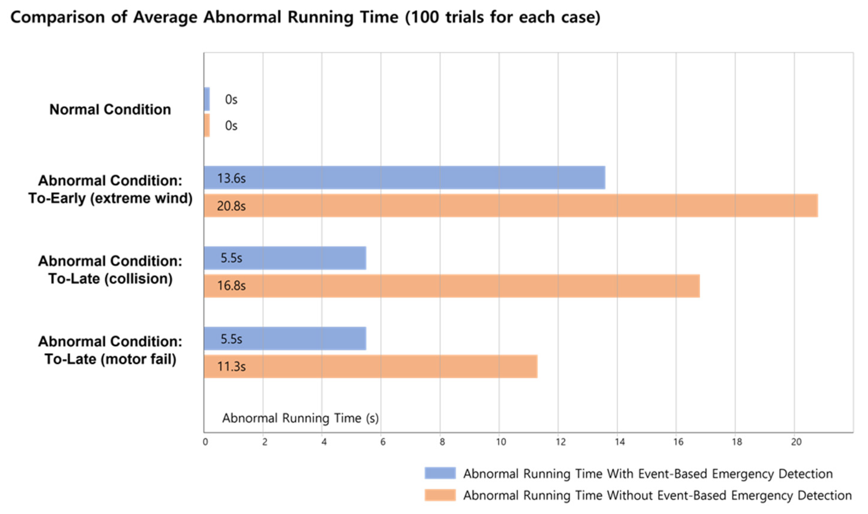
4.6. Discussions
It is important to be aware of emergencies that have already occurred due to the failure to respond in advance as quickly as possible. PID control methods seem to show sufficient performance for control within the normal range, but it is difficult to recognize situations outside the normal range of the drone, and even if it is recognized, the cases in which it can be dealt with are quite limited.
Therefore, we conducted experiments to prove that risk factors can be reduced by recognizing emergency situations outside of the normal range and making an emergency landing by mounting an event-based controller on the upper layer that operates simultaneously with the PID controller. In fact, we were able to witness expected results in case studies through simulations, as shown in
Figure 9.
As shown in
Figure 9 below, the difference can be seen numerically by comparing the abnormal running time according to the presence or absence of an event-based controller. Abnormal operation time is a concept that expresses flight time in a space outside the normal range or a time outside the normal range. In
Figure 9 below, when comparing the case of air collision, it showed a better performance of about 300%. It took 5.5 s when there was an event-based controller and 16.8 s when there was no event-based controller. We believe that reducing abnormal operation time as much as possible is essential for safe drone-service operation.
The main purpose of our approach is to immediately recognize and detect abnormal situations caused by malfunctions or external environmental factors. The experiments above proved that it is capable of handling emergency situations without diagnosing the specific cause and situations with time-window mechanisms.
However, this approach is not a sophisticated control method through intelligent control. It is also not a technique capable of failure diagnosis for analyzing the cause of an abnormal situation. In order to apply this technique, spatiotemporal statistical analysis of the predicted path must be conducted first.
In the future, through convergence research with existing control and diagnostic techniques, it will be possible to use this method not only for risk detection, but also for precise control and diagnosis.
5. Conclusions
Drone applications are widely studied in various fields. We captured the potential for urban supply-delivery applications. Unfortunately, many raise concerns about the reliability and safety of urban drone operations. Numerous studies on low-level drone-control algorithms have extended the capability and stability. Furthermore, recent studies have introduced fault-tolerant control methods and robust fault-detecting methods. However, we saw the demand to further extend the safety level to handle unexpected, abnormal situations that might occur in urban areas.
The goal of our method was to implement a high-level event-based controller in drone emergency-detection matters. We proposed a new intelligent control methodology focusing on implementing partial situation awareness. This was achieved by introducing an approach based on the time-window scope. We designed our method to operate in autonomous drone waypoint missions, cooperate with existing low-level control methods, and ensure double safety.
We designed a drone simulator and studied several emergency situations a drone might encounter in the real world. To calculate the expected interval time between waypoints, we took a statistical approach and applied conditional variables to give a slightly lenient time-window range. We were able to confirm that our approach was effective and detected emergencies well, as shown by several case-study results. As an example, we simulated an extreme wind situation (i.e., wind speed exceeds permissible limit), and the drone diagnosed an emergency when typical PID controllers could not. Without the aid of our method, the drone might have resulted in a crash.
In overall terms, our event-based approach was able to detect emergency (abnormal) events such as extreme winds and air collisions. It is true that in some cases, our approach resulted in slow reaction times. However, by applying advanced calibrations for calculating more accurate expected interval time in order to fine-tune the time-window with the placement of more narrow waypoint intervals, there seems to be more room for improvement.
We found that by applying our control method using the time-window concept in conjunction with low-level control methods, we could better detect abnormal situations than low-level-only approaches. This is because our proposal implements an understanding of situation awareness, which is lacking in other sensor-based control methods.
However, there remains a question about the robustness of our approach, since our method was only tested in simulation environments. We are currently working on real-world field tests to validate the robustness of our method. We also hope to compare emergency-detection and -handling performances with conventional drones sold on the market.
In order to enhance the proposing method, we look forward to further extending our research in two major contexts. First, we plan to explore additional methods (e.g., deep learning [
31]) to enhance the reaction time and robustness of event-based emergency detections, which is claimed to be a major weakness of our current proposal. Secondly, we wish to implement secondary position-estimating methods that operate without GPS data, since GPS errors are the biggest barriers to robust drone control in urban environments.
Moreover, we want to remark that it is necessary for us to continue to consider other ideas that can enhance and upgrade our method. As an example, we believe that an adaptive control approach can aid in this context (e.g., [
32]), which is a control strategy for stability and safety introduced initially for high-performance shipping systems.
Since safety concerns of drone operations are rising, we believe that the proposed event-based emergency-detecting method can provide effective countermeasures. This was achieved by a rather simple but realistic approach with the time-window concept. The time-window used by our algorithm express a spatiotemporal safety zone for the drone, meaning that if the drone is in bound of the time-window, it guarantees a normal condition.
Our event-based drone emergency-detection method is simple and effective to apply in the real world, and we hope our method can further extend the reliability of real-world autonomous drone services. Furthermore, we believe our method can not only detect drone emergencies, but also contribute to aviation risk analysis measures by utilizing the space–time safety zone, represented as a time-window.
Author Contributions
Conceptualization, I.K., S.-y.O. and S.-d.C.; Data curation, I.-y.K.; Formal analysis, H.-g.K. and I.-y.K.; Methodology, I.K. and S.-d.C.; Project administration, I.K. and S.-d.C.; Software, I.K. and I.-y.K.; Supervision, H.-g.K., S.-y.O. and S.-d.C.; Validation, I.K. and H.-g.K.; Visualization, I.K. and I.-y.K.; Writing–original draft, I.K.; Writing–review & editing, I.K., H.-g.K., S.-y.O. and S.-d.C. All authors have read and agreed to the published version of the manuscript.
Funding
This research was funded by the Korea Research Institute for defense Technology planning and advancement with government funds (research and development expenses for the weapons system modification and development support project) [F210009] in 2021.
Institutional Review Board Statement
Not applicable.
Informed Consent Statement
Not applicable.
Data Availability Statement
Not applicable.
Conflicts of Interest
The authors declare no conflict of interest.
References
- Merkert, R.; Bushell, J. Managing the Drone Revolution: A Systematic Literature Review into the Current Use of Airborne Drones and Future Strategic Directions for Their Effective Control. J. Air Transp. Manag. 2020, 89, 101929. [Google Scholar] [CrossRef] [PubMed]
- Scott, J.; Scott, C. Drone Delivery Models for Healthcare. In Proceedings of the 50th Hawaii International Conference on System Sciences, Hilton Waikoloa Village, HI, USA, 4–7 January 2017. [Google Scholar]
- Ghasri, M.; Maghrebi, M. Factors Affecting Unmanned Aerial Vehicles’ Safety: A Post-Occurrence Exploratory Data Analysis of Drones’ Accidents and Incidents in Australia. Saf. Sci. 2021, 139, 105273. [Google Scholar] [CrossRef]
- Plioutsias, A.; Karanikas, N.; Chatzimihailidou, M.M. Hazard Analysis and Safety Requirements for Small Drone Operations: To What Extent Do Popular Drones Embed Safety? Risk Anal. 2018, 38, 562–584. [Google Scholar] [CrossRef] [PubMed]
- Yu, Y.; Barthaud, D.; Price, B.A.; Bandara, A.K.; Zisman, A.; Nuseibeh, B. LiveBox: A Self-Adaptive Forensic-Ready Service for Drones. IEEE Access 2019, 7, 148401–148412. [Google Scholar] [CrossRef]
- Ang, K.H.; Chong, G.; Li, Y. PID Control System Analysis, Design, and Technology. IEEE Trans. Control Syst. Technol. 2005, 13, 559–576. [Google Scholar] [CrossRef]
- Babaei, A.R.; Mortazavi, M.; Moradi, M.H. Classical and Fuzzy-Genetic Autopilot Design for Unmanned Aerial Vehicles. Appl. Soft Comput. 2011, 11, 365–372. [Google Scholar] [CrossRef]
- Kim, J.; Gadsden, S.A.; Wilkerson, S.A. A Comprehensive Survey of Control Strategies for Autonomous Quadrotors. Can. J. Electr. Comput. Eng. 2020, 43, 3–16. [Google Scholar] [CrossRef]
- Smyczynski, P.; Starzec, L.; Granosik, G. Autonomous Drone Control System for Object Tracking: Flexible System Design with Implementation Example. In Proceedings of the 2017 22nd International Conference on Methods and Models in Automation and Robotics (MMAR), Międzyzdroje, Poland, 28–31 August 2017; IEEE: Manhattan, NY, USA, 2017. [Google Scholar]
- Åström, K.J.; Hägglund, T. The Future of PID Control. Control Eng. Pract. 2001, 9, 1163–1175. [Google Scholar] [CrossRef]
- Abdelkrim, N.; Aouf, N.; Tsourdos, A.; White, B. Robust Nonlinear Filtering for INS/GPS UAV Localization. In Proceedings of the 2008 16th Mediterranean Conference on Control and Automation, Ajaccio, France, 25–27 June 2008; IEEE: Manhattan, NY, USA; pp. 695–702. [Google Scholar]
- Bristeau, P.-J.; Callou, F.; Vissière, D.; Petit, N. The Navigation and Control Technology inside the AR.Drone micro UAV. IFAC Proc. Vol. 2011, 44, 1477–1484. [Google Scholar] [CrossRef]
- Burgard, W.; Derr, A.; Fox, D.; Cremers, A.B. Integrating Global Position Estimation and Position Tracking for Mobile Robots: The Dynamic Markov Localization Approach. In Proceedings of the 1998 IEEE/RSJ International Conference on Intelligent Robots and Systems. Innovations in Theory, Practice and Applications (Cat. No.98CH36190), Victoria, BC, Canada, 17 October 1998; IEEE: Manhattan, NY, USA, 2002; Volume 2, pp. 730–735. [Google Scholar]
- Albaker, B.M.; Rahim, N.A. A Survey of Collision Avoidance Approaches for Unmanned Aerial Vehicles. In Proceedings of the 2009 International Conference for Technical Postgraduates (TECHPOS), Kuala Lumpur, Malaysia, 14–15 December 2009; IEEE: Manhattan, NY, USA, 2009; pp. 1–7. [Google Scholar]
- Berbra, C.; Lesecq, S.; Martinez, J.J. A Multi-Observer Switching Strategy for Fault-Tolerant Control of a Quadrotor Helicopter. In Proceedings of the 2008 16th Mediterranean Conference on Control and Automation, Ajaccio, France, 25–27 June 2008; IEEE: Manhattan, NY, USA, 2008. [Google Scholar]
- Ducard, G.J.J. Fault-Tolerant Flight Control and Guidance Systems: Practical Methods for Small Unmanned Aerial Vehicles; Springer: London, UK, 2010; ISBN 9781849968508. [Google Scholar]
- Heredia, G.; Ollero, A. Detection of Sensor Faults in Small Helicopter UAVs Using Observer/Kalman Filter Identification. Math. Probl. Eng. 2011, 2011, 1–20. [Google Scholar] [CrossRef] [Green Version]
- Liu, C.; Jiang, B.; Patton, R.J.; Zhang, K. Hierarchical-Structure-Based Fault Estimation and Fault-Tolerant Control for Multiagent Systems. IEEE Trans. Control Netw. Syst. 2019, 6, 586–597. [Google Scholar] [CrossRef]
- Qin, L.; He, X.; Yan, R.; Zhou, D. Active Fault-Tolerant Control for a Quadrotor with Sensor Faults. J. Intell. Robot. Syst. 2017, 88, 449–467. [Google Scholar] [CrossRef]
- Rafaralahy, H.; Richard, E.; Boutayeb, M.; Zasadzinski, M. Simultaneous Observer Based Sensor Diagnosis and Speed Estimation of Unmanned Aerial Vehicle. In Proceedings of the 2008 47th IEEE Conference on Decision and Control, Cancun, Mexico, 9–11 December 2008; IEEE: Manhattan, NY, USA, 2008; pp. 2938–2943. [Google Scholar]
- Sadeghzadeh, I.; Zhang, Y. A Review on Fault-Tolerant Control for Unmanned Aerial Vehicles (UAVs). In Proceedings of the Infotech@Aerospace 2011, St. Louis, MI, USA, 29–31 March 2011; American Institute of Aeronautics and Astronautics: Reston, VA, USA, 2011. [Google Scholar]
- Chi, S.-D.; Zeigler, B.P. Hierarchical Model-Based Diagnosis for High Autonomy Systems. J. Intell. Robot. Syst. 1994, 9, 193–207. [Google Scholar] [CrossRef]
- Antsaklis, P.J.; Passino, K.M.; Wang, S.J. An Introduction to Autonomous Control Systems. IEEE Control Syst. 1991, 11, 5–13. [Google Scholar] [CrossRef]
- Besada, J.; Campaña, I.; Bergesio, L.; Bernardos, A.; de Miguel, G. Drone Flight Planning for Safe Urban Operations: UTM Requirements and Tools. Pers. Ubiquitous Comput. 2020, 26, 1085–1104. [Google Scholar] [CrossRef]
- Huang, H.; Savkin, A.V.; Huang, C. Reliable Path Planning for Drone Delivery Using a Stochastic Time-Dependent Public Transportation Network. IEEE Trans. Intell. Transp. Syst. 2021, 22, 4941–4950. [Google Scholar] [CrossRef]
- Ochoa, C.A.; Atkins, E.M. Fail-Safe Navigation for Autonomous Urban Multicopter Flight. In Proceedings of the AIAA Information Systems-AIAA Infotech@Aerospace, Kissimmee, FL, USA, 8–12 January 2018; American Institute of Aeronautics and Astronautics: Reston, VA, USA, 2017. [Google Scholar]
- Siewert, S.; Sampigethaya, K.; Buchholz, J.; Rizor, S. Fail-Safe, Fail-Secure Experiments for Small UAS and UAM Traffic in Urban Airspace. In Proceedings of the 2019 IEEE/AIAA 38th Digital Avionics Systems Conference (DASC), San Diego, CA, USA, 8–12 September 2019; IEEE: Manhattan, NY, USA, 2019; pp. 1–7. [Google Scholar]
- Yakovlev, K.S.; Makarov, D.A.; Baskin, E.S. Automatic Path Planning for an Unmanned Drone with Constrained Flight Dynamics. Sci. Tech. Inf. Process. 2015, 42, 347–358. [Google Scholar] [CrossRef]
- Shah, S.; Dey, D.; Lovett, C.; Kapoor, A. AirSim: High-Fidelity Visual and Physical Simulation for Autonomous Vehicles. In Field and Service Robotics; Springer International Publishing: Cham, Switzerland, 2018; pp. 621–635. ISBN 9783319673608. [Google Scholar]
- Epic Games. Unreal Engine. 2019. Available online: https://www.unrealengine.com (accessed on 16 May 2022).
- Jafari, M.; Xu, H. Intelligent Control for Unmanned Aerial Systems with System Uncertainties and Disturbances Using Artificial Neural Network. Drones 2018, 2, 30. [Google Scholar] [CrossRef]
- Fortuna, L.; Muscato, G. A Roll Stabilization System for a Monohull Ship: Modeling, Identification, and Adaptive Control. IEEE Trans. Control. Syst. Technol. 1996, 4, 18–28. [Google Scholar] [CrossRef]
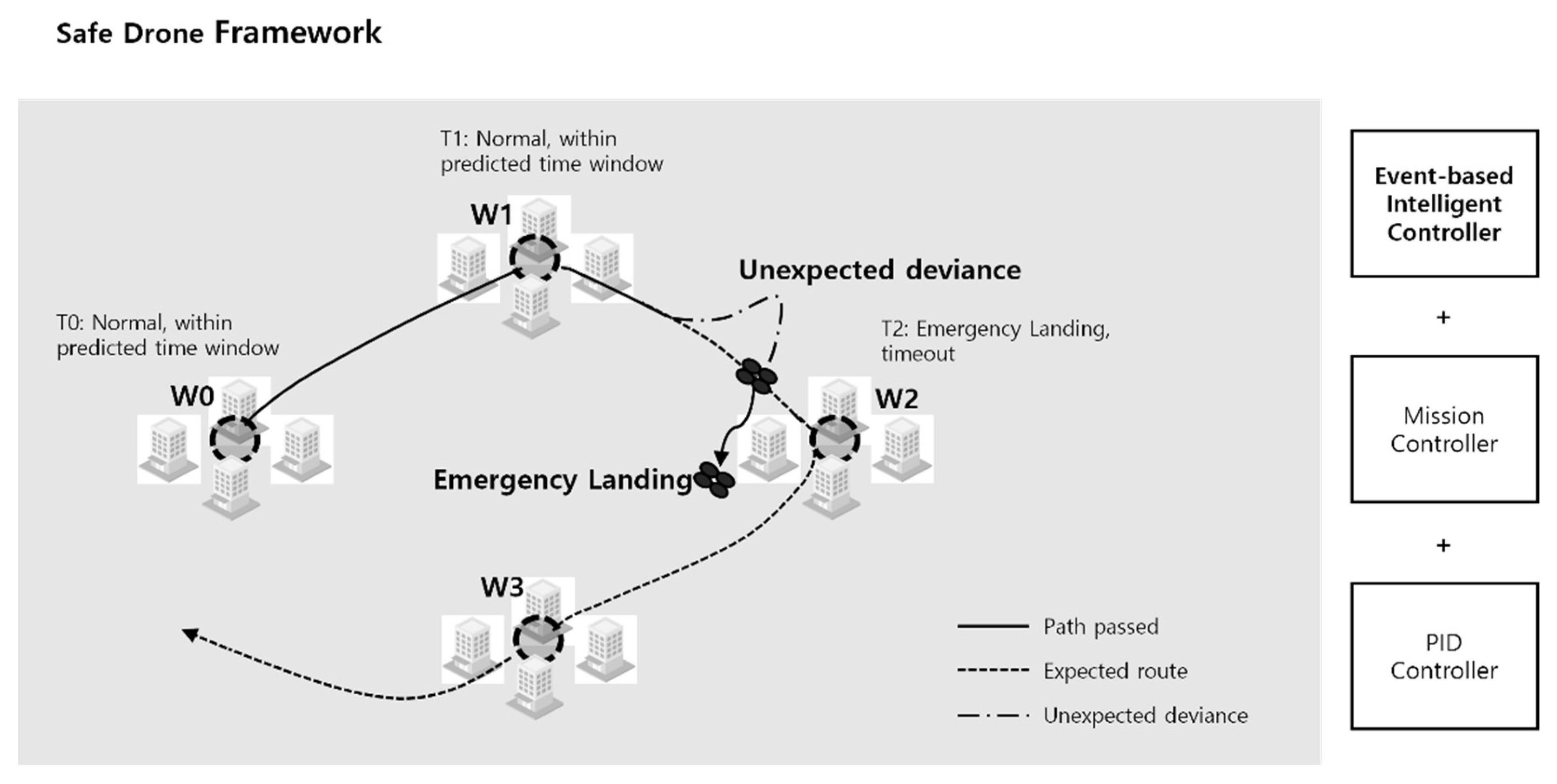
Figure 1.
Proposed safe drone framework. The event-based intelligent controller is designed to detect emergency situations with time-window check results and perform an emergency landing if needed. We mounted our event-based controller on top of lower-level controllers and designed it to work in conjunction. Our proposing method requires waypoint-based predefined flight plans in order to calculate the expected time-window and diagnose abnormality.
Figure 2.
Proposed safe drone architecture. We mounted our event-based controller on top of low-level controllers and expanded the decision-making system. Inside the event-based controller, the knowledge base stores the time-window data (e.g., Tmin, Tmax) for each waypoint that is used in path-traveling drone operations.
Figure 3.
Visual illustration of the time-window. ① (Tstart) is counted when the drone leaves a waypoint and starts to head to another. If the drone arrives the waypoint at ②, it is considered a too-early arrival, which is an abnormal situation. ③ is the minimum time boundary of a normal arrival. If the drone arrives at ④, which is inside the normal boundary, it is considered a normal arrival and the drone would proceed to the next goal. As the drone passes ⑤, which is the maximum time boundary, the time exceeds Tmax (max time), making the controller believe it is detecting an emergency and proceed with an emergency landing.
Figure 4.
Control flowchart illustrating the control loop implemented in the event-based controller. The event-based controller will not accept both early and late arrivals at each designated waypoint. If the drone does not arrive inside the time-window, the event-based controller will consider the situation an emergency.
Figure 5.
(a). Drone movement 2D log on normal case. The results show the drone managed the mission well with no failures. Both the drones with and without an event-based controller showed similar routes. (b). Time-window check results. The black dots illustrate the actual arrival time for each waypoint interval relative to each time-window. In this case, the drone made it in all normal arrival time-windows. Tarrival showed a decreasing pattern over time as the drone approached the desired speed.
Figure 6.
(a). Drone movement 2D log on abnormal case: too early. The vertical red line marks the moment when the drone detected an emergency and proceeded with an emergency landing. The wind was applied from the beginning of the mission, which is marked with a yellow line. Due to extreme wind conditions, the drone could not provide stable operations. (b). Time-window check results. The drone did not make it in the normal arrival time-windows on the path from c to d. The yellow line at the beginning indicates that extreme wind conditions were applied from the beginning of the flight. The red line indicates the moment where the event-based controller detected an abnormal situation due to early arrival.
Figure 7.
(a). Drone movement 2D log on abnormal case: too late. The vertical red line marks the moment when the drone detected an emergency and proceeded with an emergency landing. Due to a collision, the drone far exceeded the expected path, which could possibly have led to secondary collisions. (b). Time-window check results. The drone did not make it in the normal arrival time-windows on the path from b to c. The yellow line after the drone left b indicates the moment of the collision. The red line indicates the moment where the event-based controller detected an abnormal situation due to maximum time-window being exceeded.
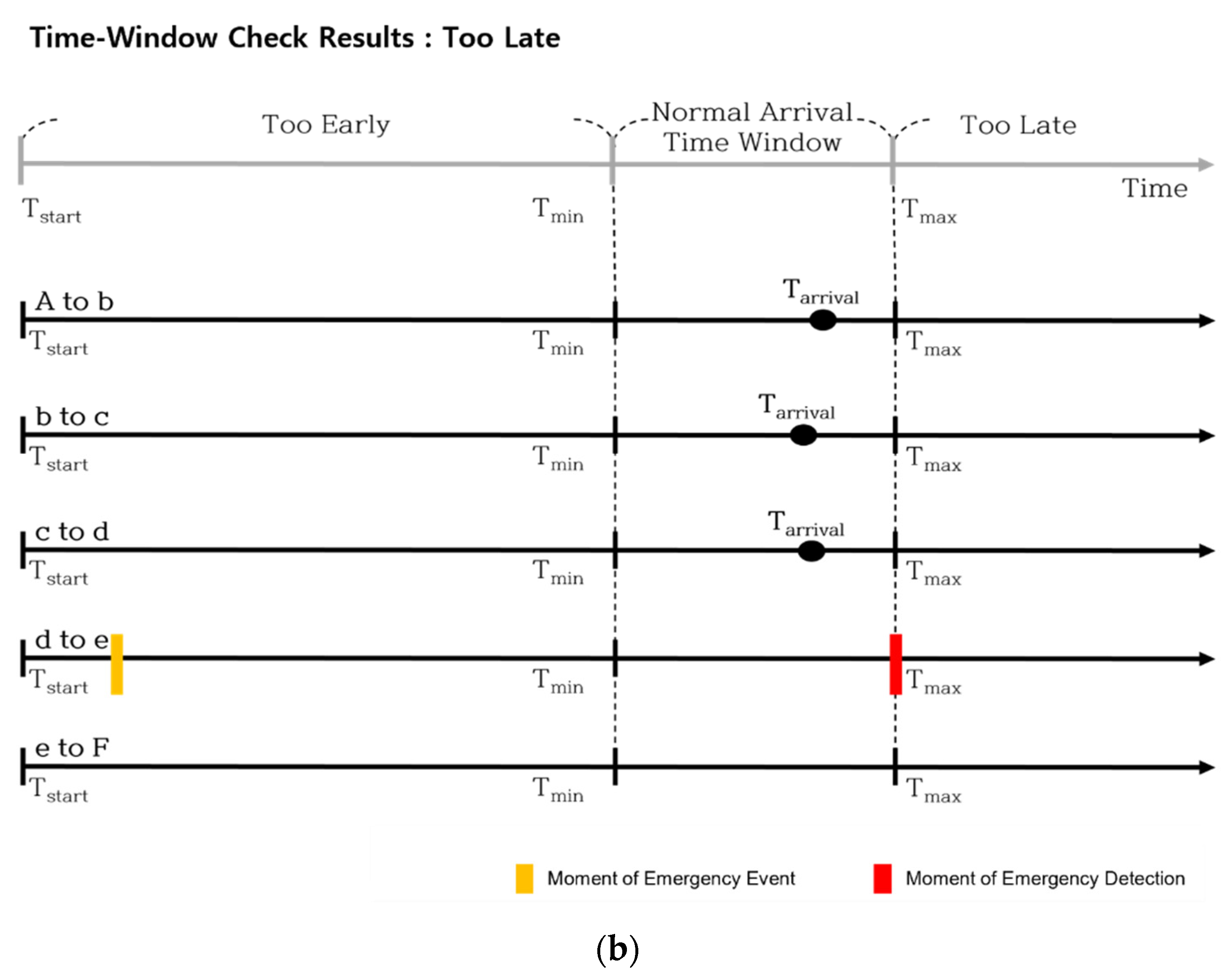
Figure 8.
(a). Drone movement 2D log on abnormal case: too late. The vertical red line marks the moment when the drone detected an emergency and proceeded with an emergency landing. Due to a motor failure, the drone far exceeded the expected path, which could possibly have led to secondary collisions. (b). Time-window check results. The drone did not make it in the normal arrival time-windows on the path from d to e. The yellow line after the drone left d indicates the moment of the motor failure. The red line indicates the moment where the event-based controller detected an abnormal situation due to max time-window being exceeded.
Figure 9.
Comparison of average abnormal running time. Each case was conducted 100 times to reasonably compare the results. It turned out that too-early cases took more time to detect than too-late cases, where both too-late cases were detected within about 5.5 s on average.
Figure 9.
Comparison of average abnormal running time. Each case was conducted 100 times to reasonably compare the results. It turned out that too-early cases took more time to detect than too-late cases, where both too-late cases were detected within about 5.5 s on average.
Table 1.
The actual numerical time data for each waypoint, including Tstart, Tmin, Tmax, and the actual arrival time Tarrival for the normal case. All five Tarrival resulted in arriving inside the time-window without any issue. Each start time was calculated after the Tarrival data were retrieved and did not consider computational delays.
| Path | Tstart | Tmin | Tmax | Tarrival |
|---|
| A to b | 0.00 s | 4.50 s | 5.50 s | 5.23 s |
| b to c | 5.23 s | 9.73 s | 10.73 s | 10.26 s |
| c to d | 10.26 s | 14.76 s | 15.76 s | 15.14 s |
| d to e | 15.14 s | 19.64 s | 20.64 s | 19.92 s |
| e to F | 19.92 s | 24.42 s | 25.42 s | 24.59 s |
Table 2.
The actual numerical time data including Tstart, Tmin, Tmax, and the actual arrival time Tarrival for the extreme wind case. On the path from c to d, the Tarrival was outside the time-window. The initial call for an emergency landing would have been 13.61 s away from the start of the mission. This is a considerably long period of time, but better than lacking the ability to detect such conditions with using PID controllers alone.
| Path | Tstart | Tmin | Tmax | Tarrival |
|---|
| A to b | 0.00 s | 4.50 s | 5.50 s | 4.74 s |
| b to c | 4.74 s | 9.24 s | 10.24 s | 9.27 s |
| c to d | 9.27 s | 13.77 s | 14.77 s | 13.61 s |
| d to e | | | | |
| e to F | | | | |
Table 3.
The actual numerical time data including Tstart, Tmin, Tmax, and the actual arrival time Tarrival for the air collision case. The first interval from A to b was inside the time-window. However, due to the collision after waypoint b, the drone struggled to return to its mission path and exceeded the time-window. This type of emergency is extremely dangerous, yet hard to handle.
| Path | Tstart | Tmin | Tmax | Tarrival |
|---|
| A to b | 0.00 s | 4.50 s | 5.50 s | 5.22 s |
| b to c | 5.22 s | 9.72 s | 10.72 s | x |
| c to d | | | | |
| d to e |
| e to F |
Table 4.
The actual numerical time data including Tstart, Tmin, Tmax, and the actual arrival time Tarrival for the air-collision case. For the first three intervals from A to d it arrived inside the time-window. However, due to the motor failure after waypoint d, the drone struggled to return to its mission path and exceeded the maximum time-window. This type of emergency is extremely dangerous, yet hard to handle.
| Path | Tstart | Tmin | Tmax | Tarrival |
|---|
| A to b | 0.00 s | 4.50 s | 5.50 s | 5.28 s |
| b to c | 5.28 s | 9.78 s | 10.78 s | 10.32 s |
| c to d | 10.32 s | 14.82 s | 15.82 s | 15.51 s |
| d to e | 15.51 s | 20.01 s | 20.01 s | x |
| e to F | | | | |
| Publisher’s Note: MDPI stays neutral with regard to jurisdictional claims in published maps and institutional affiliations. |
© 2022 by the authors. Licensee MDPI, Basel, Switzerland. This article is an open access article distributed under the terms and conditions of the Creative Commons Attribution (CC BY) license (https://creativecommons.org/licenses/by/4.0/).


