Article

Calculation for Permanent Displacement of Single Slip Surface of Multi-Stage Loess Slope Based on Energy Method

1
School of Civil Engineering, Shandong Jianzhu University, Jinan 250101, China
2
Northwest Research Institute Co., Ltd. of C.R.E.C, Lanzhou 730030, China
3
School of Civil Engineering, Lanzhou University of Technology, Lanzhou 730050, China
*
Author to whom correspondence should be addressed.
Appl. Sci. 2022, 12(17), 8426; https://doi.org/10.3390/app12178426
Submission received: 29 July 2022 / Revised: 19 August 2022 / Accepted: 19 August 2022 / Published: 24 August 2022
(This article belongs to the Special Issue Geo-Environmental Problems Caused by Underground Construction)

Abstract

:
At present, there are still some gaps in the theoretical calculation of the permanent displacement of the multi-stage loess slope under the action of earthquake. Therefore, this paper firstly uses the GEO-Studio finite element software to explore the influence of the comprehensive slope rate on the permanent displacement when the slope rate of each grade of multi-stage loess slope changes and the stage of multi-stage slope changes. The results show that it is feasible to use the comprehensive slope rate to calculate the permanent displacement of the sliding body of the multi-stage loess slope under the action of earthquake. On the basis of this conclusion, in order to simplify the calculation of permanent displacement of potential sliding soil, the other geometric parameters of the multi-stage loess slope are replaced by the comprehensive slope rate, combined with the Newmark slider displacement analysis method and energy conservation principle, and then the calculation method of permanent displacement of potential sliding soil of multi-stage loess slope under the action of earthquake is deduced. Through an example, the permanent displacement calculated by the proposed algorithm are compared with those calculated by the PLAXIS 3D software and GEO-Studio software. The results show that the permanent displacement calculated by this method is close to that calculated by the GEO-Studio software, and the difference is only 2%, and thus, the rationality of the proposed method for calculating the permanent displacement of the multi-stage loess slope under the action of earthquake is verified. The algorithm proposed in this paper provides a theoretical reference for the calculation of the permanent displacement of multi-stage loess slope under the action of earthquake.

1. Introduction

Loess is a kind of unsaturated soil with large pores, and loess in China is mainly distributed in the northwest region [1,2,3,4,5]. In recent years, as the “Western Development” strategy and “Belt and Road Initiative” strategy have entered a key stage of accelerated development, there will be a large number of multi-stage loess slopes when various infrastructure is built along them. However, China is also a country with frequent earthquakes, and it is very easy to cause multi-stage loess slope landslides under the action of earthquake, which seriously threatens people’s lives and property safety [6,7]. Therefore, it is particularly important to study the calculation of permanent displacement of multi-stage loess slope under the action of earthquake [8,9,10]. At present, the research on the calculation of permanent displacement of the slope under the action of earthquake is as follows. The finite slider displacement analysis method was put forward by Newmark [11] in 1965. It is suggested that the index of possible displacement of potential sliding soil in earth–rockfill dam during earthquake should be used in evaluating the seismic safety of earth–rockfill dam, and a theoretical model for calculating the permanent displacement of potential sliding soil is put forward. Now, this method is widely used in the evaluation of slope stability during earthquake. Since the Newmark slider displacement calculation model was proposed, many scholars have proposed many modified models based on this theory to consider the dynamic response of sliding blocks. These methods include the slider analysis method of coupling and decoupling, among which the simplified model proposed by Makdisi et al. [12] is the most representative one. Steven et al. [13] introduced the dynamic response of the material on the potential sliding surface into the traditional calculation method of slider displacement. Ellen et al. [14,15,16] compared the difference between decoupling and coupling methods in calculating permanent displacement, proposing a coupling-based analysis model considering sliding mass and sliding plane nonlinearity. Zhang et al. [17,18] provide a strict method for the general calculation of elastodynamic plane problems according to the radial wave function expansion and transfer matrix method. Many scholars have also developed a variety of empirical prediction models for the permanent displacement of potential slip surface of the slope under the action of earthquake, where the permanent displacement is a function of slope geometry, soil parameters or one or more ground motion parameters. Bray et al. [19] proposed a simplified semi-empirical program, which can be used to evaluate the displacement of natural soil or landfill structures that may slip during earthquake. Hsieh et al. [20] used the regression model and regression method to improve the JB93 formula and JB98 formula to calculate Newmark displacement by discussing the relationship between Avias strength and Newmark displacement and the relationship between critical acceleration and Newmark displacement. Du et al. [21] quantitatively studied the influence of the change in slope properties on calculating the displacement of the slope in a Newmark rigid body and fully coupled analysis. Through Monte Carlo simulation, the changes in soil strength, groundwater level, nonlinear soil properties and other parameters are studied, and the influence of these parameters on the displacement prediction of rigid and soft slope is studied comprehensively. Some scholars have also extended the original model with only one potential sliding surface and slider to a nested Newmark slider displacement calculation model with multiple potential sliding surfaces and sliders. Song et al. [22] derived the sliding model of two blocks on the sliding model of one block, and then derived the three-block model, discussed seven possible sliding modes, and put forward a method for calculating the permanent seismic displacement of infinite slope. In addition to the above research, some scholars have also studied the displacement of the slope strengthened by supporting structure under the action of earthquake. Considering the reinforcement effect of a frame with a prestressed anchor on the slope, Ye et al. [23,24,25,26] established the analysis model of dynamic response and displacement of the slope under the action of earthquake, deduced its calculation theory, and put forward the analysis method of dynamic response and displacement of the slope strengthened by a frame with prestressed anchor under the action of earthquake.
To sum up, it is not difficult to see that the existing research on the permanent displacement of slope under earthquake is mainly focused on the correction of the Newmark slider displacement calculation model, the development of empirical prediction models of permanent displacement, the establishment of the nested Newmark slider displacement calculation model with multiple slip surfaces and sliders, and the calculation for permanent displacement of single-stage slope strengthened by supporting structure. However, there are still some gaps in the theoretical calculation of the permanent displacement of multi-stage slope and multi-stage loess slope. At present, there are still some gaps in the theoretical calculation of the permanent displacement of multi-stage loess slope under the action of earthquake. Therefore, this paper firstly uses the GEO-Studio finite element software to explore the influence of the comprehensive slope rate on the permanent displacement when the slope rate of each grade of multi-stage loess slope changes and the stage of multi-stage slope changes. The results show that it is feasible to use the comprehensive slope rate to calculate the permanent displacement of the sliding body of multi-stage loess slope under the action of earthquake. On the basis of this conclusion, in order to simplify the calculation of permanent displacement of potential sliding soil, the other geometric parameters of multi-stage loess slope are replaced by the comprehensive slope rate, combined with Newmark slider displacement analysis method and energy conservation principle, and then the calculation method of permanent displacement of potential sliding soil of multi-stage loess slope under the action of earthquake is deduced. Through an example, the permanent displacement calculated by the proposed algorithm are compared with those calculated by PLAXIS 3D finite element software and GEO-Studio finite element software, and the rationality of the proposed method for calculating the permanent displacement of multi-stage loess slope under the action of earthquake is verified. The algorithm proposed in this paper provides a theoretical reference for the calculation of permanent displacement of multi-stage loess slope under the action of earthquake.

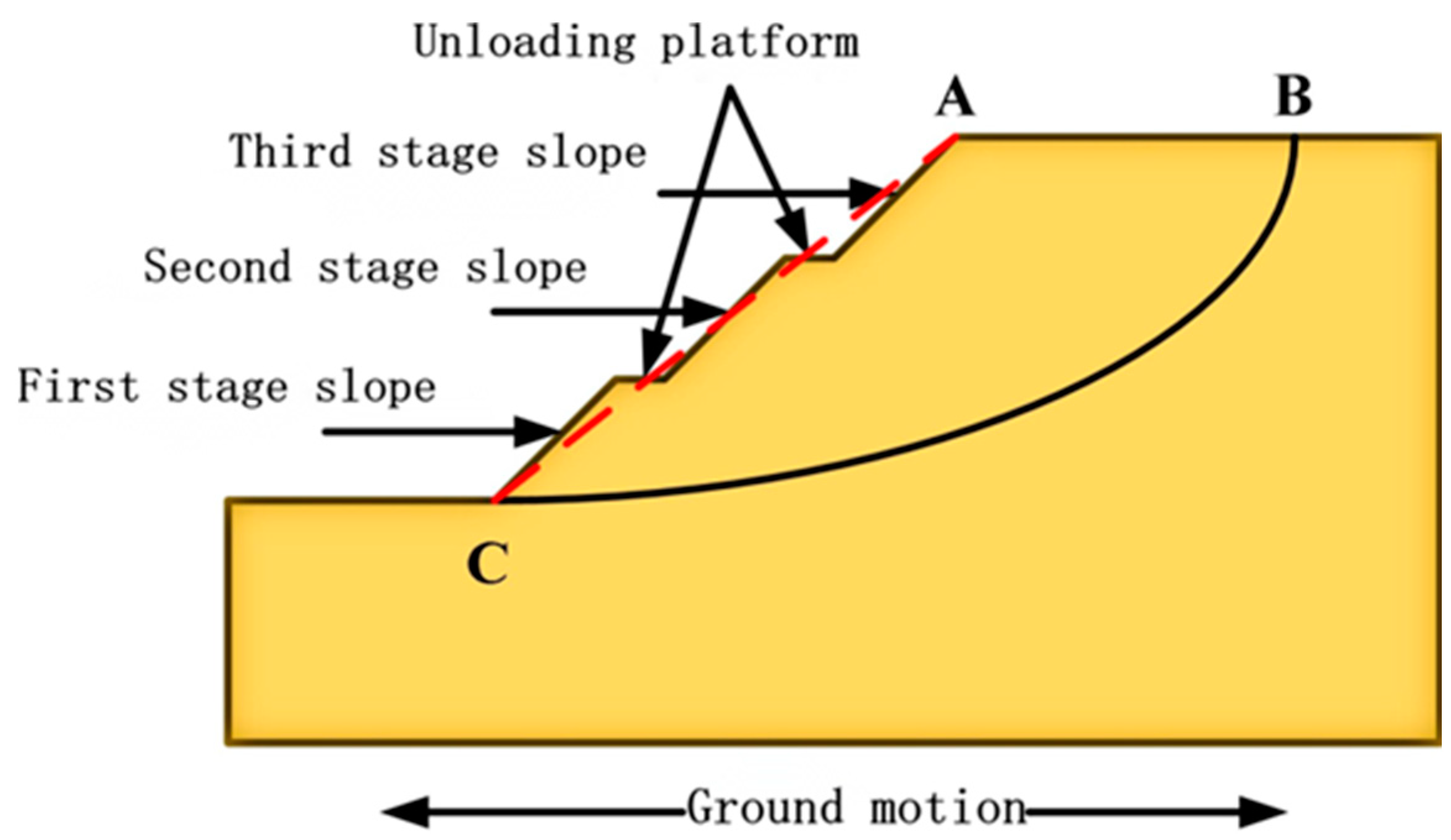
2. Influence of the Comprehensive Slope Rate on Permanent Displacement

In the process of excavation of multi-stage loess slope, the slope is unloaded by setting the width of the platform and changing the original slope rate, which leads to the redistribution of stress in the slope. In terms of geometric characteristics, compared with single-stage loess slope, multi-stage loess slope has more definitions of unloading platform width, each grade height, each grade slope rate and slope series. The comprehensive slope rate is the ratio of the total slope height to the distance from the top to the toe of slope of the multi-stage slope, so the comprehensive slope rate can reflect these geometric parameters quantitatively to a certain extent. First of all, in this paper, the influence of comprehensive slope on the permanent displacement of multi-stage loess slope under the action of earthquake is explored by numerical simulation software, and then the well-defined physical quantity of comprehensive slope is introduced to simplify the process of theoretical calculation. In terms of qualitative permanent displacement, a minimum safety factor Fs less than 1.2 is defined as the failure of the slope, and the corresponding horizontal displacement of the sliding soil is the permanent displacement of the slope under the action of earthquake, and the subsequent permanent displacement is expressed according to this definition. Taking the working condition A-1 in Table 1 as an example, the SLOPE/W module based on quasi-static method is used to calculate the stability of the slope after earthquake in GEO-Studio numerical simulation software, and the slip surface form and minimum safety factor of the slope are shown in Figure 1.
It can be seen from Figure 1 that the minimum safety factor is 0.903. According to the definition of this paper, the slope has been destroyed and has produced permanent displacement. By calculating the rest of the working conditions in this paper, it is found that the minimum safety factor is less than 1.2, which means that these slopes all cause permanent displacement.

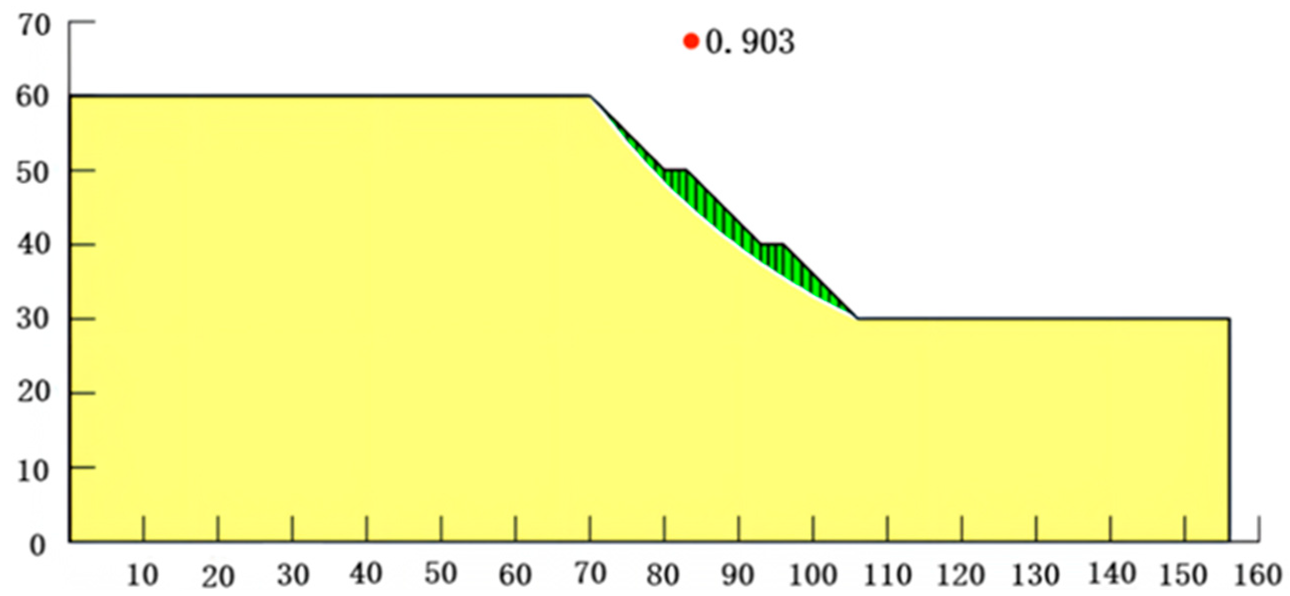
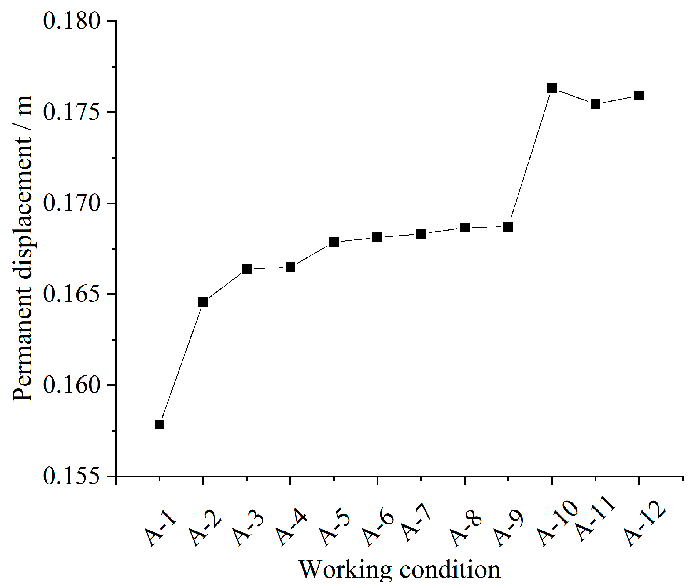
2.1. When the Slope Rate of Each Grade of Multi-Stage Slope Is Changed

In order to explore the influence of the change in the slope rate of each grade on the permanent displacement of potential sliding soil of multi-stage loess slope under the action of earthquake, a three-stage loess slope model is established by using GEO-Studio geotechnical finite element software. The total height of the slope is H =30 m, the height of each slope is h1 = h2 = h3 = 10 m, the width of the platform is 3 m, the friction angle of soil is φ = 15°, the unit weight of soil is γ = 16.6 kN/m3, the slope rate of each grade is 1:0.75~1:1.25, and the slope as a whole shows a steep trend at the upper part and gentle at the lower part. Additionally, a total of 12 working conditions are set for simulation calculation when the comprehensive slope rate is 1:1.2; the specific working conditions are shown in Table 1.
The A-1 analysis model is shown in Figure 2. The model soil parameters are loess-like silt, the linear elastic model is adopted, the yield criterion is the Mohr–Coulomb yield criterion, the model Poisson’s ratio is υ = 0.3, and the initial dynamic shear modulus is Gmax = 220 Mpa. First, the model is analyzed by the initial static analysis. The boundary condition of the model is that the horizontal and vertical directions at the bottom are fixed, the horizontal directions on both sides are fixed, and the vertical directions on both sides are free. Then, the model is calculated and analyzed by equivalent linearity calculation and analysis. The boundary condition of the model is that the horizontal and vertical directions at the bottom are fixed, the vertical directions on both sides are fixed, and the horizontal directions on both sides are free.
In the dynamic calculation of the model, the EI-Centrol seismic wave with a duration of 30 s and a peak acceleration of 0.2 g is selected for each working condition, which is input at the bottom of the model. The boundary condition of the model is that the horizontal and vertical directions at the bottom of the model are fixed, the vertical directions on both sides of the model are fixed, and the horizontal directions on both sides of the model are free. Because it is defined that the permanent displacement is the horizontal displacement of the slope after experiencing the whole duration range of the earthquake when the safety factor is less than 1.2, the maximum horizontal displacement after the calculation of the model under each working condition is selected, which is the permanent displacement. The calculated permanent displacement of the slope under each working condition in Table 1 is shown in Figure 3.
As can be seen from Figure 3, when the slope rate of each grade slope changes but the comprehensive slope rate remains unchanged, the minimum horizontal permanent displacement of multi-stage loess slope under the action of earthquake is 0.15784 m under A-1 working condition, and the maximum value is 0.17633 m under A-10 working condition. Additionally, the difference between the maximum permanent displacement and the minimum permanent displacement is 0.01849 m, which is only 10.486% of the maximum permanent displacement. According to the above analysis, it can be shown that it is feasible to use the comprehensive slope rate to calculate the permanent displacement under the condition that the slope rate of each grade changes, but the comprehensive slope rate remains unchanged. It can also be seen from Figure 3 that the maximum horizontal displacement is most directly related to the slope rate of the first-stage slope. When the first-stage slope rate remains unchanged, the difference in the maximum horizontal displacement is very small, such as the working condition of A-10~A-12.

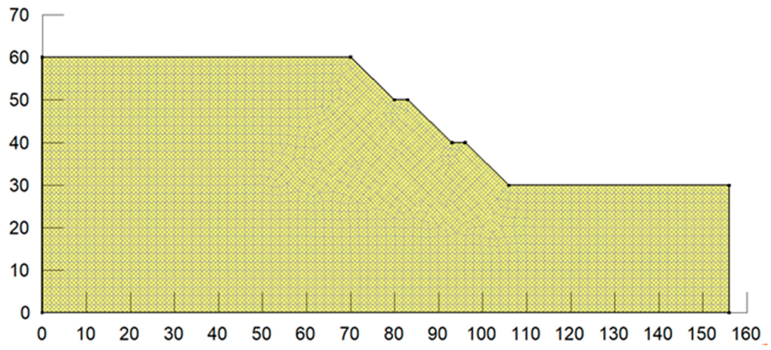
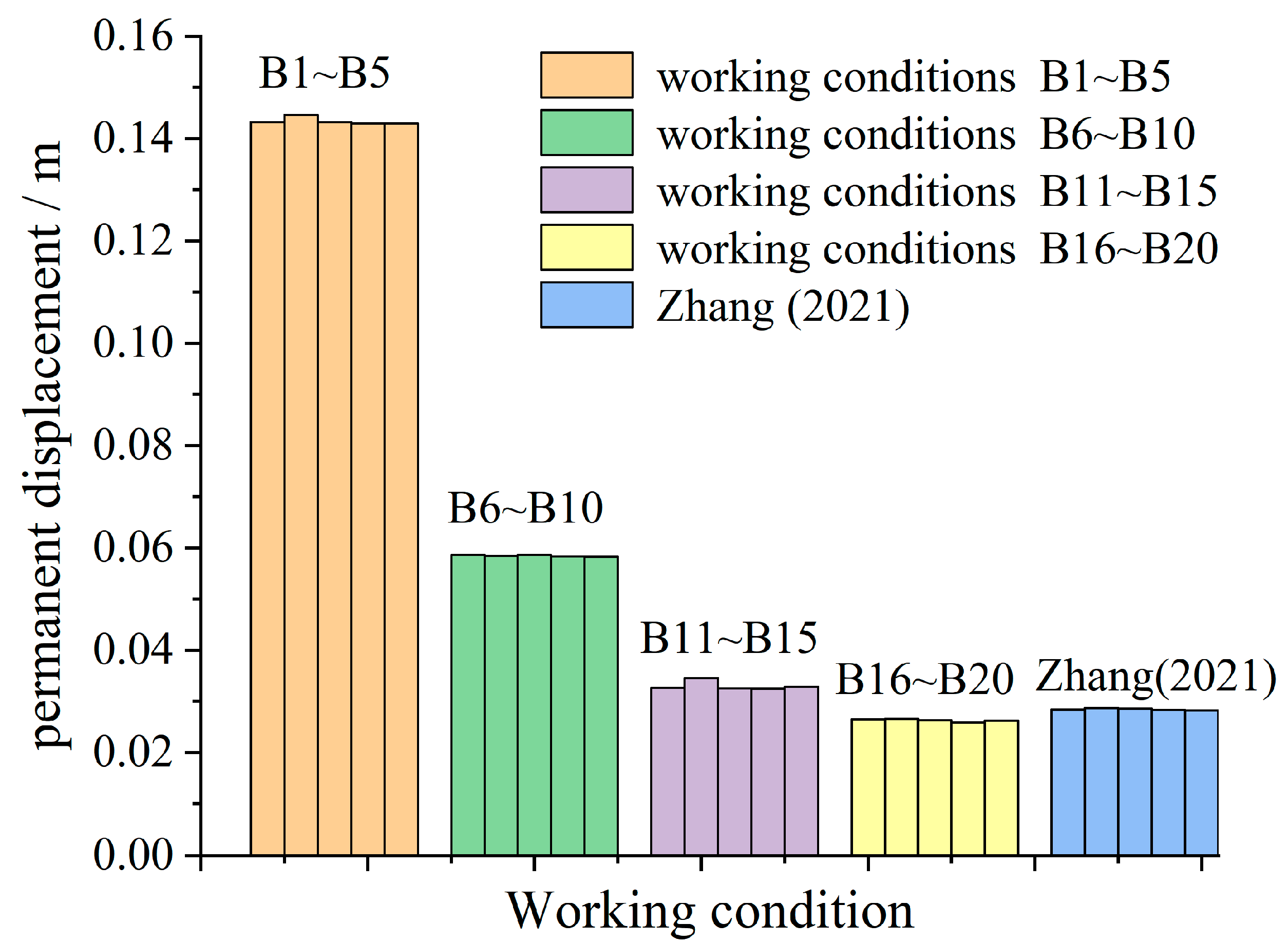
2.2. When the Stage of Multi-Stage Slope Is Changed

In order to explore the influence of the comprehensive slope ratio on the permanent displacement under the condition that the stage of multi-stage loess slope changes and other geometric parameters remain unchanged, the slope model as shown in Table 2 is established. The specific model parameters are the same as those in Section 2.1, only the slope series is changed, and the slope rate of each grade is the same under the same working condition. A total of 20 calculation conditions are set up, the specific conditions are shown in Table 2, and the research results of Zhang [27] are introduced for comparative analysis.
The calculated permanent displacement of the slope under each working condition in Table 2 is shown in Figure 4.
It can be seen from Figure 4 that under the condition of constant comprehensive slope rate, the change in the slope series has little influence on the permanent displacement of multi-stage loess slope under the action of earthquake. In the research results of Zhang [27], the total slope angle of the multi-level loess slope model is 41.4°, the width of the platform is 4 m, the total height of the slope is 30 m, and the stage number ranges from 1 to 5. From the research results of Zhang [27], it can also be seen that the change in stage number has little influence on the permanent displacement. Therefore, it is also feasible to use the comprehensive slope rate to calculate the permanent displacement when the stage of multi-stage loess slopes changes, but the comprehensive slope rate remains unchanged.

3. Analysis of Energy Response of Multi-Stage Loess Slope under the Action of Earthquake

Combining the contents of Section 2.1 and Section 2.2, under the condition that the comprehensive slope rate is constant and other geometric parameters (slope rate of each stage, height of each stage and slope stage of the multi-stage loess slope) change, the variation range of potential sliding soil permanent displacement is small. In order to simplify the calculation of the permanent displacement of the potential sliding soil, the other geometric parameters of the multi-stage loess slope can be replaced by the comprehensive slope rate, and the theoretical analysis and calculation can be carried out. When calculating the permanent displacement of the potential sliding soil, the multi-stage loess slope can also be regarded as a single-stage slope with the same slope rate as the comprehensive slope rate of original slope.

3.1. Basic Assumptions

According to the relevant flow law of rock and soil mass and the principle of limit analysis, in order to simplify the calculation and approach the actual project, the following assumptions are made [23,28,29].
(1)
The strength of rock and soil mass obeys the Mohr–Coulomb strength criterion.
(2)
When the rock and soil mass fails, the yield surface is convex everywhere and conforms to the relevant flow laws.
(3)
When the potential sliding body slides with the lower soil body, its sliding surface is assumed to be a logarithmic spiral along the tangential direction.
(4)
When the potential sliding body is in the limit equilibrium state that is about to slide, the acceleration of the potential sliding body is its yield acceleration.
(5)
There is no gradual failure of the plastic failure of the soil on the slip surface; that is, the cohesive force of the soil c and the angle of internal friction of the soil φ remain unchanged during the earthquake duration.

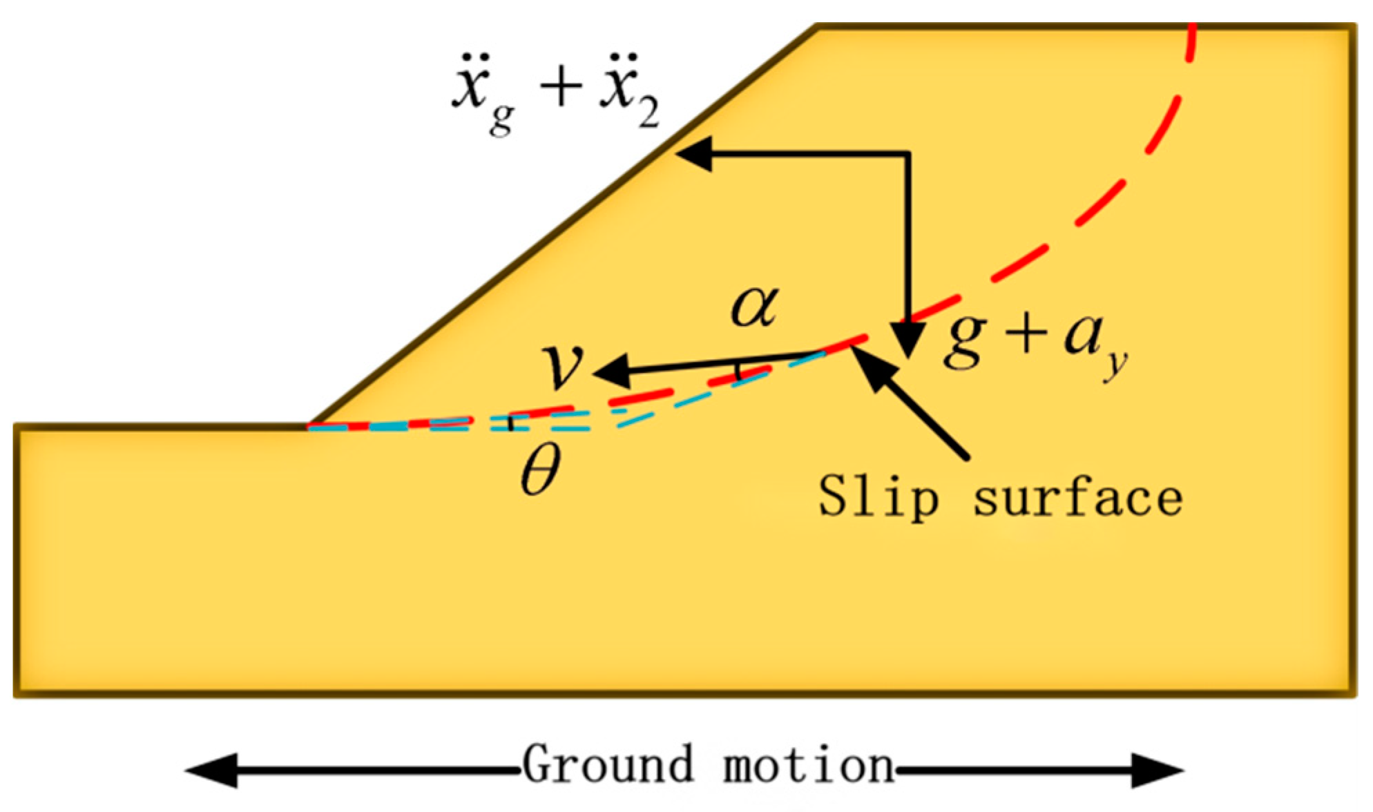
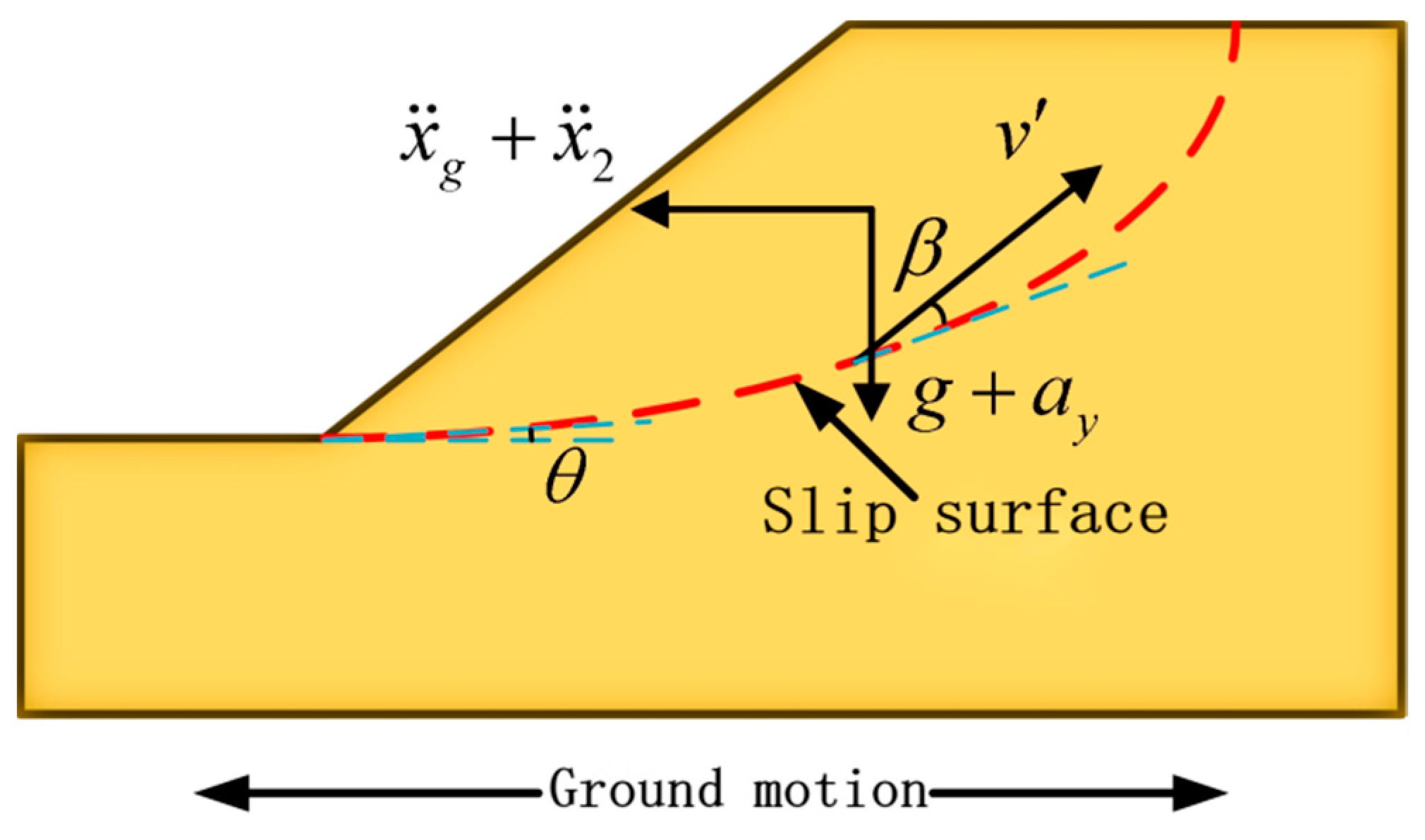
3.2. Critical Acceleration of Potential Sliding Soil

As shown in Figure 5, the potential sliding soil ABC appears on the slope surface under the action of earthquake. According to the Newmark slider displacement analysis method, when the soil slides under horizontal and vertical seismic forces, the potential sliding soil ABC will appear in the following four states. The first state is relatively static (the seismic acceleration does not exceed the yield acceleration of the potential sliding soil), the second state is limit equilibrium (the seismic acceleration reaches the yield acceleration of the potential sliding soil), the third state is positive downward sliding (the seismic acceleration exceeds the positive yield acceleration of the potential sliding soil) and the fourth state is reverse upward sliding (the negative seismic acceleration exceeds the negative critical acceleration of the potential sliding soil) [23,28].
It is assumed that the comprehensive slope rate of the multi-stage loess slope is 1:n, the inclination between the potential sliding soil and the lower part of the sliding soil is θ, and both horizontal and vertical seismic forces are considered in the theoretical analysis and calculation. When the potential sliding soil ABC is in the limit equilibrium state under earthquake excitation, the positive critical acceleration of the potential sliding soil a c r ( t ) and the negative critical acceleration a c o ( t ) of the potential sliding soil can be solved by using the upper limit theorem of plastic limit analysis.

3.2.1. Positive Downward Critical Acceleration

When the positive seismic acceleration reaches the critical acceleration of the potential sliding soil, the sliding soil will be in the state of limit equilibrium about to slide at this moment. At this time, the potential sliding soil has a downward velocity v relative to the lower soil, the angle between the velocity and the slip surface is α, and the calculation diagram is shown in Figure 6. According to the theory of plastic limit equilibrium, the external force power w ˙ 0 is equal to the internal force power w ˙ i [23].
The external force power w ˙ 0 is composed of two parts, namely, the power made by gravity P w and the power made by seismic inertia force P i [28]:
P w = m ( g + a y ) v sin ( θ α )
P i = m ( x ¨ g + x ¨ ) v cos ( θ α )
where m is the mass of the potential sliding soil, g is the acceleration of gravity, x ¨ g is the horizontal acceleration of the lower part of the potential sliding soil, and x ¨ is the acceleration of the potential sliding soil relative to the lower soil.
The dissipated power of internal force w ˙ i is composed of three parts, namely, the energy dissipation of the sliding surface during the motion Pt, the energy dissipation of the potential sliding soil due to the plastic deformation of the soil at the moment of instability Pc, and the energy dissipation caused by the Coulomb damping when the potential sliding soil is in the limit equilibrium state Pd [28]:
P t = c l v cos φ
P c = c s v cos φ
P d = m v [ ( g + a y ) cos θ ( x ¨ g + x ¨ ) sin θ ] tan φ cos α
According to [23]
P w + P i = P t + P c + P d
The forward critical acceleration of the potential sliding body at this time a c r ( t ) can be obtained:
a c r ( t ) = c l cos φ + c s cos φ + m ( g + a y ) cos θ tan φ cos α m cos ( θ α ) + m sin θ tan φ cos α m ( g + a y ) sin ( θ α ) m cos ( θ α ) cos α + m sin θ tan φ cos α

3.2.2. Negative Downward Critical Acceleration

When the seismic acceleration changes from positive to negative, the velocity of the potential sliding soil relative to the lower soil gradually decreases until the seismic acceleration reaches the negative critical acceleration of the potential sliding soil. Then, the potentially sliding soil will be in limit equilibrium state about to slide upward under seismic excitation, and the angle between its velocity v and the potential sliding surface is β, and the direction is upward. The calculation diagram is shown in Figure 7.
At this time, the power made by the external force w ˙ 0 and the dissipation power of the internal force w ˙ i are:
w ˙ 0 = m ( g + a y ) v sin ( θ + β ) + m ( x ¨ g + x ¨ ) v cos ( θ + β )
w ˙ i = c l v cos β + c s v cos β + m v [ ( g + a y ) cos β + ( x ¨ g + x ¨ ) sin β ] tan φ cos β
From w ˙ 0 = w ˙ i [23], the negative critical acceleration a c o ( t ) can be obtained when the potential sliding soil is in the limit equilibrium state, and it should be noted that the negative critical acceleration is a negative value:
a c o ( t ) = c l cos β + c s cos β + m ( g + a y ) cos β tan φ cos β m cos ( θ + β ) cos α m sin θ tan φ cos β m ( g + a y ) sin ( θ + β ) m cos ( θ + β ) cos α m sin θ tan φ cos β

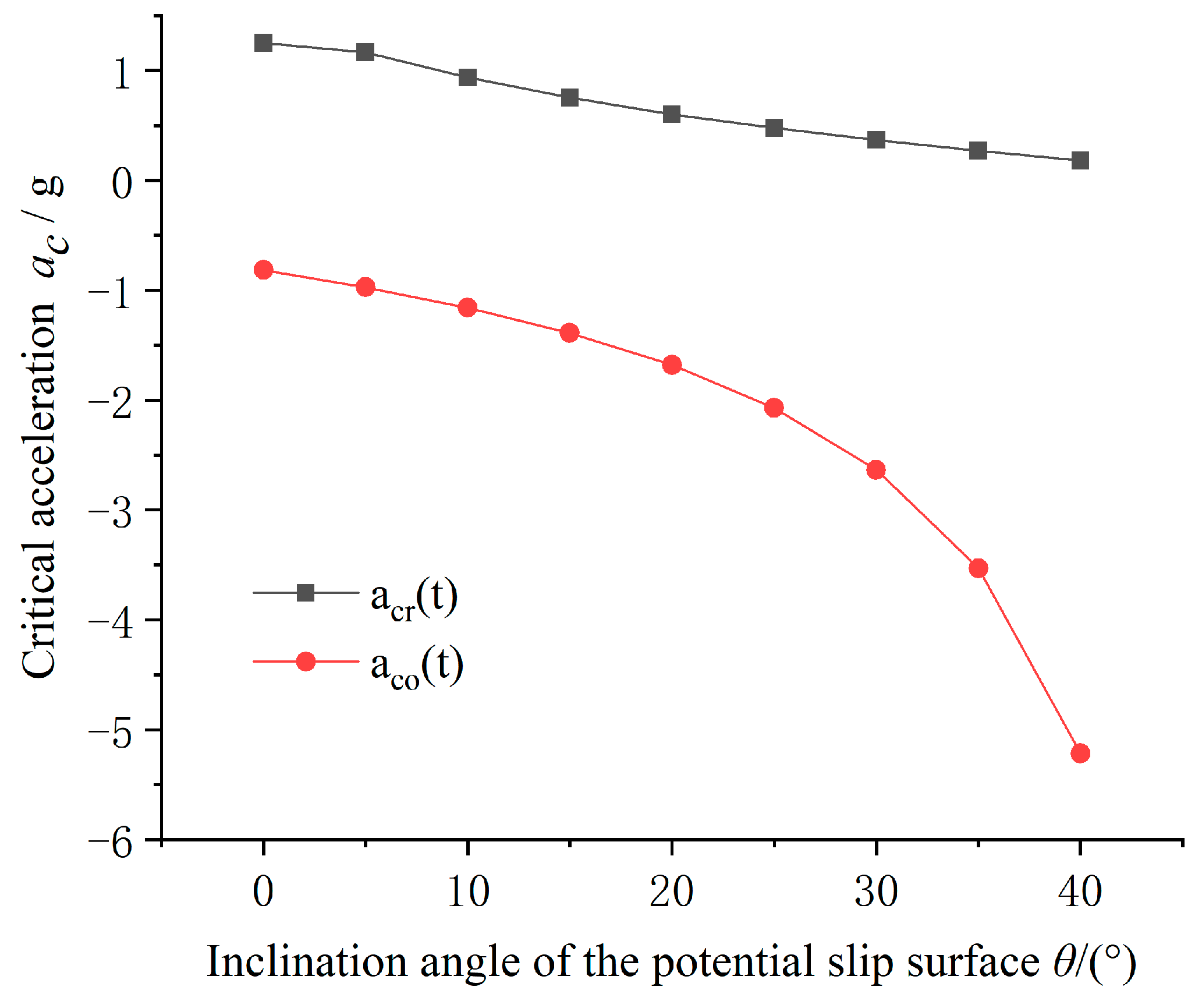
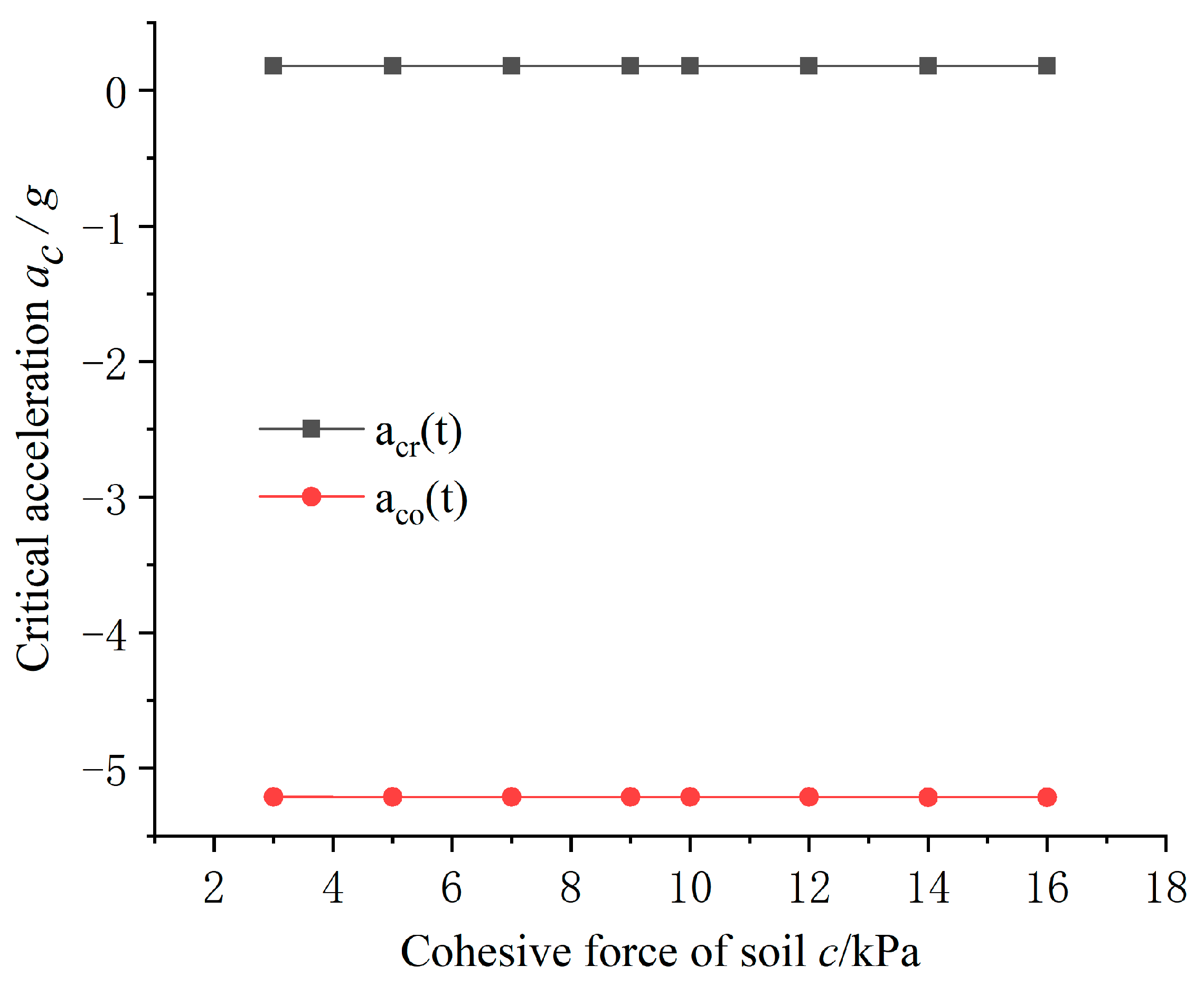
3.3. Influence of Inclination Angle of Slip Surface θ and Soil Parameters on Positive and Negative Critical Acceleration

Since the vertical acceleration of potential sliding soil is no longer a fixed value, it is a more complex value with the change in inclination angle and soil parameters when the inclination angle θ and soil parameters (internal friction angle φ and cohesive force c) are changed. Therefore, the vertical acceleration ay is not considered in the analysis of this section, which makes it equal to 0. The effects of the inclination angle of the potential slip surface θ and the friction angle of the soil φ and cohesive force c of the soil on the critical acceleration of the potential sliding soil ac are shown in Figure 8, Figure 9 and Figure 10. In order to simplify the calculation process, the width of the potential sliding soil is 1 m. The geometric, physical and mechanical parameters of the slope are shown in Table 3.
It can be seen from Figure 8 that as the increase in the inclination angle of the potential slip surface θ, the absolute value of the positive critical acceleration | a c r ( t ) | decreases with a very small range, which accords with the general law from the point of view of stability. When the inclination angle θ increases from 0 to 40°, the absolute decrease in positive critical acceleration is only 1.07. The absolute value of negative critical acceleration | a c o ( t ) | increases continuously when the inclination angle of potential slip surface θ increases from 0 to 40°, and when the inclination angle of the potential slip surface θ reaches 40°, the absolute value of the negative critical acceleration exceeds 5 g. It can also be seen from Figure 8 that the assumption that the Newmark slider displacement analysis method is not applicable to the sliding soil system with deeper potential slip surface is reasonable. When the slip surface is deep, the negative critical acceleration increases sharply, and it is impossible for the general earthquake and velocity to reach the value shown in Figure 8. The Newmark slider displacement analysis method does not consider the negative critical acceleration, so it does not consider the reverse displacement.
It can be seen from Figure 9 and Figure 10 that the friction angle and cohesive force of soil have much less influence on the critical acceleration relative to the inclination angle of the potential sliding surface. It is proved that the energy dissipated by damping and soil deformation is much smaller than the energy dissipated by the motion of the potential sliding soil.

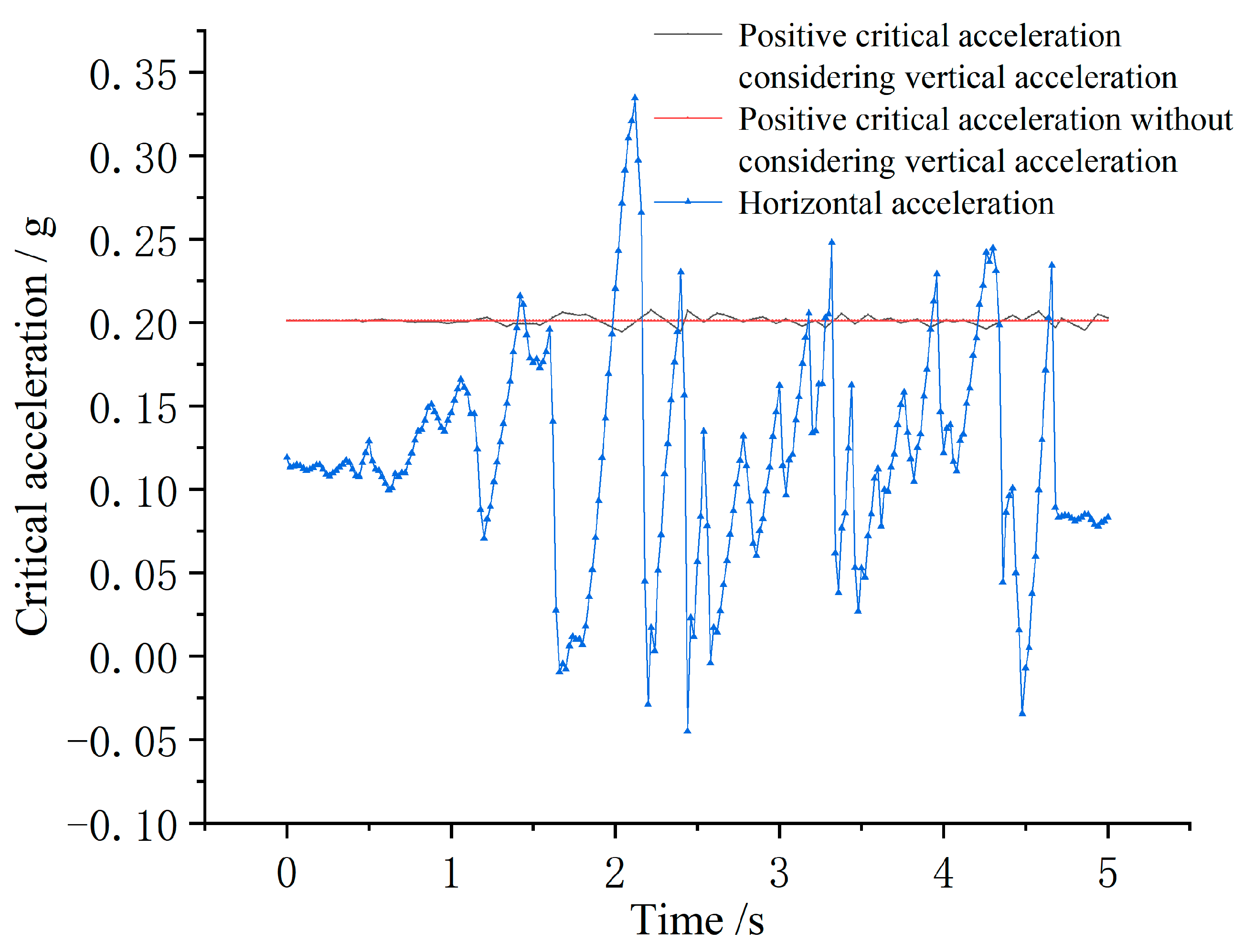
3.4. Influence of Vertical Acceleration on Critical Acceleration in the Action of Earthquake

When an earthquake occurs, both horizontal seismic excitation and vertical seismic excitation act on the slope soil at the same time. Most scholars only consider the influence of horizontal seismic action when considering the dynamic response of the slope under the action of earthquake, but some new studies show that vertical seismic force can change the distribution of dynamic stress in structure, which cannot be ignored in structural seismic and dynamic response analysis [30]. Taking the slope in Table 1 as an example, a monitoring point is set at the top of the slope, and an EI-Cenrol seismic wave with a peak acceleration of 0.2 g is applied at the bottom of the model under the case for considering the vertical acceleration. Then, the horizontal acceleration and the positive critical acceleration within the earthquake duration of 0~5 s is drawn, as shown in Figure 11.
As shown in Figure 11, in the calculation of the positive critical acceleration, it can be seen from the red line that the positive critical acceleration is a certain value without considering the vertical critical acceleration, which is 0.201 g, and its value is a variable quantity with time when considering vertical acceleration. The magnitude and direction of the vertical acceleration directly affect the magnitude and direction of the critical acceleration. The positive critical acceleration increases when the vertical acceleration is in the same direction as the critical acceleration, and the positive critical acceleration decreases when the vertical acceleration is opposite to the critical acceleration. It can also be seen from Figure 11 that a c r ( t ) fluctuates up and down around a c r over time, and the number of horizontal acceleration exceeding the critical acceleration is limited. If the vertical acceleration is not considered and the critical acceleration is regarded as a fixed value to calculate the permanent displacement, there may be some errors, which will affect the calculation of the permanent displacement.

3.5. Energy Equation of Sliding Soil System

From the analysis of Figure 6, it can be concluded that under the combined action of horizontal and vertical seismic excitation, sliding soil will move along the potential sliding surface after the acceleration of the sliding soil exceeds the yield acceleration, and the differential equation of motion is:
m ( x ¨ g + x ¨ ) cos θ c l μ m [ ( g + a y ) cos θ + ( x ¨ g + x ¨ ) sin θ ] + m ( g + a y ) sin θ = 0
where m is the friction coefficient between the sliding soil mass and the lower soil mass, μ = tan φ .
Equation (11) can be rearranged:
( 1 + μ tan θ ) m ( x ¨ g + x ¨ ) + c l cos θ + μ m ( g + a y ) m ( g + a y ) tan θ = 0
During the whole process of the earthquake, the soil of the slope has been in the energy field under the earthquake excitation, and the input, transformation and consumption of energy have been carried out and balanced. On the one hand, the soil is constantly transmitting energy; on the other hand, it continues to consume energy because of the displacement caused by motion. The differential equation of motion of the potential sliding soil is established only in the limit equilibrium state, which can only reflect the energy state of one moment, and cannot represent the process of motion change process of potential sliding soil at other times in the duration range of earthquake. By quantifying the process of energy change in sliding soil in the energy field, the energy response equation of sliding soil under earthquake can be obtained [28,29].
The absolute displacement of potential sliding soil x g + x at both ends of Equation (12) is integrated in the earthquake duration range [0, t], and the absolute energy response equation of potential sliding soil is obtained:
0 t ( 1 + μ tan θ ) m ( x ¨ g + x ¨ ) ( x ˙ g + x ˙ ) d t + 0 t c l cos θ ( x ˙ g + x ˙ ) d t + 0 t μ m ( g + a y ) ( x ˙ g + x ˙ ) d t 0 t m ( g + a y ) tan θ ( x ˙ g + x ˙ ) d t = 0
Simplification can be obtained:
1 + μ tan θ 2 m ( x ˙ g + x ˙ ) 2 + [ c l cos θ + μ m 2 ( g + a y ) ] x m ( g + a y ) x tan θ = ( 1 + μ tan θ ) 0 t m ( x ¨ g + x ¨ ) x ˙ g d t
where x ˙ g is the velocity of the lower soil, x is the displacement of the potential sliding soil relative to the lower soil, that is, the permanent displacement of the potential sliding soil, x ˙ g + x ˙ is the absolute velocity of the potential sliding soil, and x ¨ g + x ¨ is the absolute acceleration of the potential sliding soil.
Equation (14) is suitable for any time within the duration range of the earthquake; that is, the values of energy input and output of the whole sliding soil system are always balanced in the earthquake duration range. Figure 12 shows the acceleration of potential sliding soil and lower soil during a certain period of time when the vertical acceleration of the lower soil is not taken into account.
During the time period of [0, t1], the acceleration of the lower soil mass (the seismic acceleration) does not exceed the positive and negative critical acceleration of the potential sliding soil, and the potential sliding soil remains relatively static with the lower soil. The magnitude of the static friction force at the potential slip surface is equal to the seismic force at the moment, and the direction changes continuously with the direction of the seismic force to counteract the effect of the seismic force. With the change in the direction of the seismic force, the static friction force continues to perform positive and negative work, the kinetic energy of the whole landslide system increases and decreases continuously, and the total energy keeps balance. Additionally, the speed of potential sliding soil is always the same as that of the lower soil. During the time period of [t1, t2], the acceleration of the lower soil exceeds the positive critical acceleration a c r of the potential sliding soil, and the potential sliding soil breaks the limit equilibrium state that is about to slide downward and begins to slide downwards. In this process, the acceleration of the lower soil and the sliding soil are x ¨ g and a o r , respectively, where the former is accelerated motion, and the latter is uniform acceleration motion. During the time period of [t2, t3], the lower soil begins to decelerate, and its acceleration is x ¨ g . Due to the action of inertia, the sliding soil still accelerates uniformly, and its acceleration is a c r . At the t3 moment, the velocity of the lower soil and the sliding soil are consistent again. During the whole time period of [t1, t3], The kinetic energy of the system is increased by the work performed by the shear force at the slip surface, the vertical seismic force and the gravity, and the kinetic energy is reduced by the friction work between the lower soil and the sliding soil at the slip surface. At t4 moment, the acceleration of the lower soil exceeds the reverse critical acceleration a o r of the sliding soil, and the sliding soil begins to slide upward. At the t5 moment, the velocity of the lower soil and the sliding soil are consistent again. Differently from the fact that the work performed by gravity and the shear force at the slip surface increases the system energy in the whole time period of [t1, t3], the work performed by gravity and shear force at the slip surface in the whole time period of [t4, t5] will dissipate part of the seismic input energy. The movement mode of sliding soil in the time period of [t6, t7] is the same as that of [t1, t3].

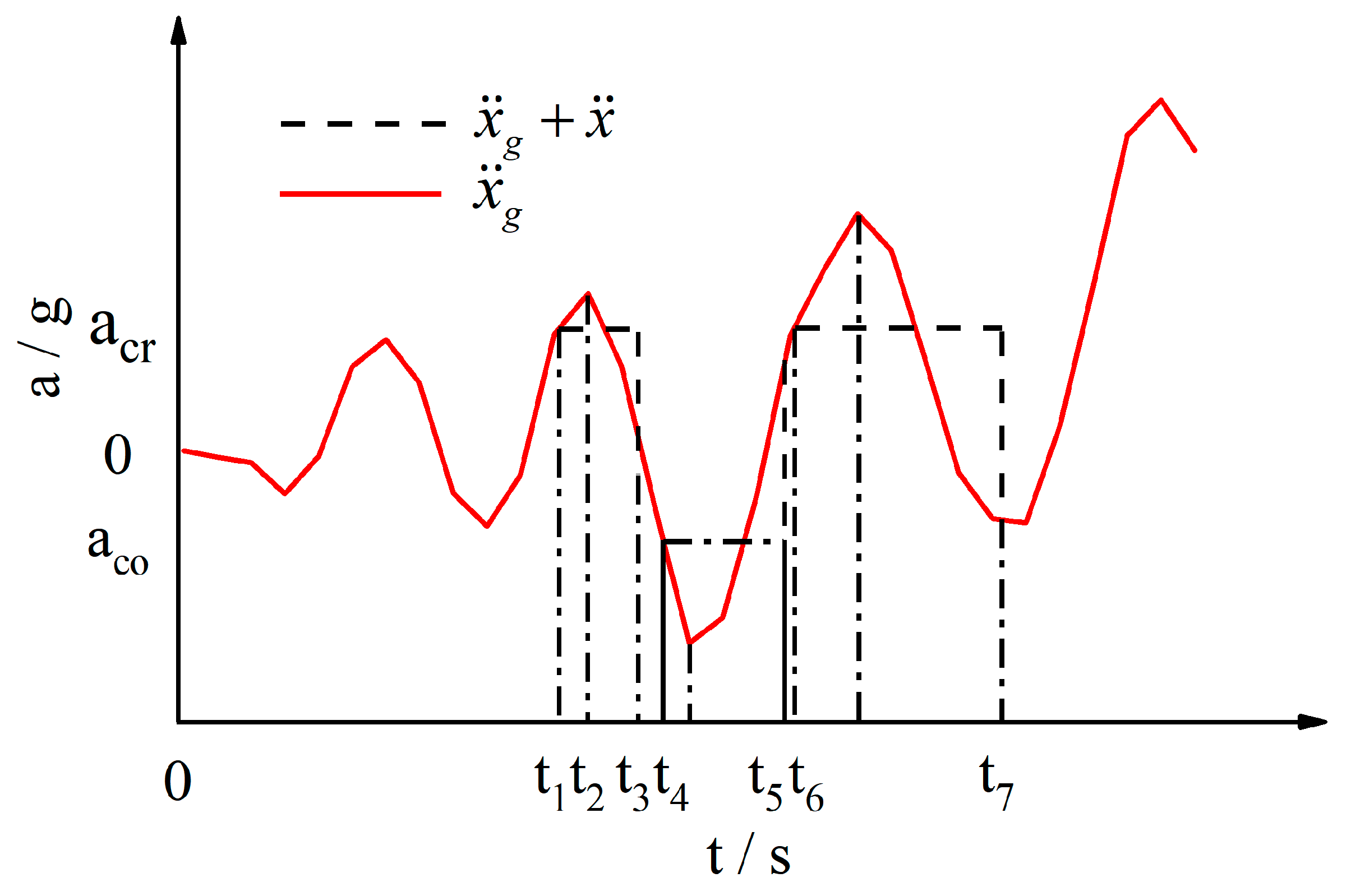
3.6. Critical Input Power and Permanent Displacement

From the term of horizontal seismic input energy at the right end of Equation (14), the instantaneous input energy of the block Δ E E Q H with a time interval of Δ t within the duration range of the earthquake can be obtained as follows:
Δ E E Q H = ( 1 + μ tan θ ) Δ t m x ¨ z x ˙ g d t
At this time, the condition of block sliding is that the instantaneous input energy Δ E E Q H of the block is greater than the kinetic energy increase in the block in the time period of Δ t . After the instantaneous input energy is obtained from Equation (15), the instantaneous input power P r can be obtained by deriving it:
P r = ( 1 + μ tan θ ) m x ¨ z x ˙ g
By deriving the first kinetic energy term at the left end of Equation (14), the critical input power of the block P c r can be obtained:
P c r = ( 1 + μ tan θ ) m x ¨ z x ˙ z
When the earthquake input power is less than the critical input power of the block, this part of the input energy can be fully converted and consumed inside the slope, so it will not trigger the block to slide, which is relatively safe. On the contrary, the energy input by ground motion will not be safely converted and consumed. After deriving the kinetic energy term and making it equal to the instantaneous input power of the block P r e s , the residual input power of the permanent displacement of the block P r e s can be obtained:
P r e s = ( 1 + μ tan θ ) m x ¨ z ( x ˙ g x ˙ z )
The residual input power P r e s is integrated within [0, t] during the duration of the earthquake, the part of the residual power input energy of the block under earthquake action can be obtained, which is defined as the residual energy of the block E R E S [29]:
E R E S = ( 1 + μ tan θ ) m 0 t x ¨ z ( x ˙ g x ˙ z ) d t
From Equations (14) and (19), the residual energy E R E S can be defined as the difference between the absolute input energy of horizontal earthquake E E Q H and the absolute kinetic energy of sliding soil E K , that is, E R E S = E E Q H E K . The generation of residual energy is the trigger condition of the potential sliding of sliding soil, and contributes to the generation of permanent displacement of sliding soil together with the increase or decrease in potential energy produced by sliding of soil and the input energy of the vertical seismic wave. Considering the dynamic friction coefficient of sliding soil μ = tan φ , according to the definition of residual energy and Equation (19), the following results can be obtained:
[ c l cos θ + m ( g + a y ) ( tan φ tan θ ) ] x = ( 1 + tan φ tan θ ) m 0 t x ¨ z ( x ˙ g x ˙ z ) d t
According to Equation (20), the permanent displacement x of the block in the whole earthquake duration range can be obtained.

4. Example Verification

4.1. Model Parameters

It is known that the total height of three-stage homogeneous loess slope is 30 m, the height of each slope is h1 = h2 = h3 = 10 m, the slope rate of each grade is i1 = i2 = i3 = 1:0.75, the width of the platform is B1 = B2 = B3 = 2 m, the friction angle of soil is φ = 32°, the cohesive force is c = 15 kPa, and the natural heavy of soil is γ = 16.6 kN/m3. The safety grade of the slope is grade II, and the seismic fortification intensity in this area is VIII.

4.2. Comparison of Calculation Results

The calculated time history of positive critical acceleration and horizontal acceleration is shown in Figure 13. The numerical simulation adopts EI-Centrol seismic wave with horizontal peak acceleration of 0.2 g and vertical peak acceleration of 0.2 g, and the duration is 30 s. The positive and negative critical acceleration time histories of sliding soil are calculated by Equations (7) and (10), respectively, and the average values of positive and negative critical acceleration are 0.185 g and −5.214 g, respectively. The permanent displacement calculated in this paper is compared with that calculated by PLAXIS 3D software and Geo-Studio software, and the comparison results are shown in Table 4.
It can be seen from Figure 13 that the calculated value of negative critical acceleration is much larger than the peak value of horizontal acceleration, so it can be concluded that the negative critical acceleration has no effect on permanent displacement. As can be seen from Table 4, the permanent displacement calculated by this paper is larger than that calculated by PLAXIS 3D and smaller than that calculated by GEO-Studio, which is closer to that calculated by GEO-Studio. This is because the Geo-Studio software is a two-dimensional calculation software and is relatively simplified in the calculation process, and the derivation process of this paper does not consider the influence of the lateral deformation of soil on the calculation of permanent displacement. To a certain extent, the calculation method in this paper is reliable.

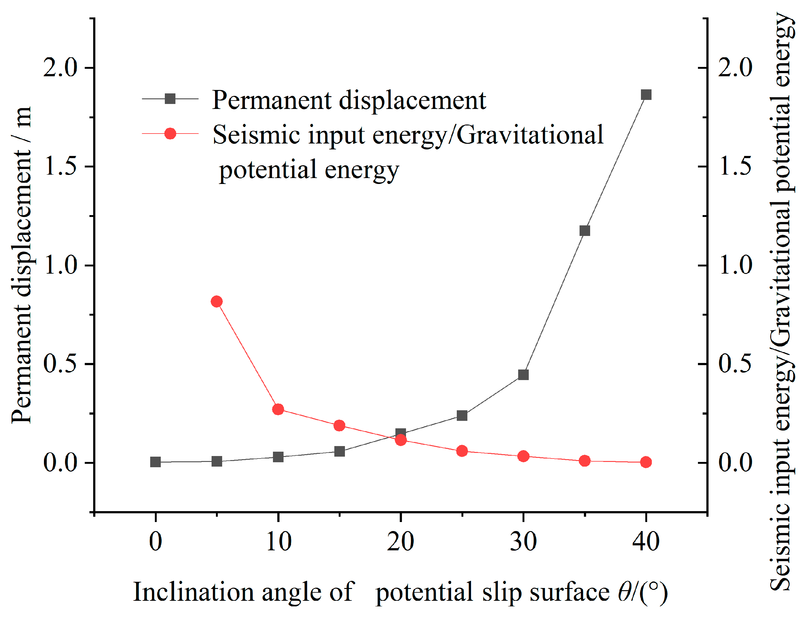
4.3. Influence of the Change in Gravity Potential Energy on Permanent Displacement

In order to explore the influence of the reduction in gravity potential energy on the permanent displacement of the slope, the inclination angle of the slip surface is changed without considering the vertical acceleration, the critical acceleration, permanent displacement, gravity potential energy drop and seismic input energy of sliding soil are calculated by using the derived theoretical formulas, as shown in Table 5. The ratio of the decrease in seismic input energy to gravitational potential energy and the variation of permanent displacement with the inclination angle of slip surface are calculated, as shown in Figure 14.
It can be seen from Table 5 and Figure 14 that with the increase in the inclination angle of slip surface, the permanent displacement changes greatly at 30°, and it suddenly increases sharply from the steady increase before 30°. Meanwhile, the ratio of seismic input energy to gravitational potential energy drop decreases sharply after 10°, and the absolute values of positive critical acceleration and negative critical acceleration decrease and increase, respectively. When the inclination angle of the potential sliding surface is greater than 15°, the contribution of the seismic input energy to the permanent displacement of the slope under the action of the earthquake is relatively limited. It shows that for the permanent displacement of the slope excited by earthquake, earthquake is only a triggering condition and factor, and the real factor causing permanent displacement is gravitational potential energy.

5. Conclusions

  • Through a large number of numerical simulation tests, it is concluded that the geometric characteristics of the slope cannot be taken into account to a certain extent when calculating the permanent displacement of sliding soil of multi-stage loess slope under the action of earthquake; in addition, it is feasible to use the comprehensive slope to calculate the permanent displacement of the sliding body of multi-stage loess slope under the action of earthquake.
  • On the premise of using the comprehensive slope rate to calculate the permanent displacement of multi-stage loess slope under earthquake, based on the energy method, combined with the Newmark slide displacement method, considering soil deformation and damping, the formulas for calculating positive and negative critical acceleration and permanent displacement of sliding soil are reasonable.
  • The critical acceleration of the sliding soil is mainly affected by the inclination angle of the sliding surface, but not by the soil parameters. The earthquake is only an inducing factor for the permanent displacement of the sliding soil, and the decrease in gravitational potential energy plays a key role in the permanent displacement.
  • The method derived in this paper comprehensively considers the influence of negative critical acceleration on the solution of permanent displacement when the inclination angle of slip surface is small and the seismic acceleration is large, and based on the principle of energy balance in the process of calculation and derivation, the calculation results are thus more accurate.

Author Contributions

Conceptualization: S.Y.; data curation: X.Z. (Xiaobing Zhang); formal analysis: X.Z. (Xiaobing Zhang), X.Z. (Xin Zhang) and S.Y.; investigation: X.Z. (Xiaobing Zhang), X.Z. (Xin Zhang) and S.Y.; methodology: X.Z. (Xiaobing Zhang) and S.Y.; software: X.Z. (Xiaobing Zhang); writing—original draft: X.Z. (Xiaobing Zhang) and S.Y.; writing—review and editing: X.Z. (Xiaobing Zhang), X.Z. (Xin Zhang) and S.Y. All authors have read and agreed to the published version of the manuscript.

Funding

This research was funded by the National Natural Science Foundation of China (No. 52168050) and the National Natural Science Foundation of China (No. 51768040).

Institutional Review Board Statement

Not applicable.

Informed Consent Statement

The authors listed in this paper all agree to publish this paper.

Data Availability Statement

The data of simulation and theoretical calculation in the article are not freely available due to legal concerns and commercial confidentiality. Nevertheless, all the concepts and procedures are explained in the presented research, and parts of the research may be available upon request.

Acknowledgments

The authors of the present work feel grateful and would like to thank Northwest Research Institute Co., Ltd. of C.R.E.C, Shandong Jianzhu University, National Natural Science Foundation of China, Lanzhou University of Technology, for providing financial and technical support in research.

Conflicts of Interest

The authors declare that they have no conflict of interest.

References

  1. Xie, Y.L.; Liu, X.R.; Yan, C.G.; Yang, Z.P.; Li, J.C.; Zhou, Z.J.; Yue, X.B. Research progress of special soil and rock engineering slopes. China Civ. Eng. J. 2020, 53, 93–105. [Google Scholar]
  2. Li, Y.R.; Shi, W.H.; Aydin, A.; Beroya-Eitner, M.A.; Gao, G.H. Loess genesis and worldwide distribution. Earth-Sci. Rev. 2020, 201, 1–22. [Google Scholar] [CrossRef]
  3. Bai, B.; Nie, Q.; Zhang, Y.K.; Wang, X.L.; Hu, W. Cotransport of heavy metals and SiO2 particles at different temperatures by seepage. J. Hydrol. 2021, 597, 125771. [Google Scholar] [CrossRef]
  4. Ye, S.H.; Huang, A.P. Sensitivity of high fill slope stability factors under seismic conditions. Soil Mech. Found. Eng. 2020, 57, 356–363. [Google Scholar]
  5. Xu, L.; Gao, C.; Lan, T.; Lei, J.; Zuo, L. Influence of grading on the compressibility of saturated loess soils. Geotech. Lett. 2020, 10, 198–204. [Google Scholar] [CrossRef]
  6. Tian, W.T.; Sun, J.J.; Wang, L.M.; Xu, S.H.; Liu, K.; Sun, Y. Research progress and frontier scientific problems in loess dynamics. Chin. J. Geotech. Eng. 2015, 37, 2119–2127. [Google Scholar]
  7. Yan, Z.X.; Guo, B.; He, X.; Jiang, P. Study of effect of platform width on dynamic response and failure mechanism of stepped slopes under earthquake. Rock Soil Mech. 2012, 33, 352–358. [Google Scholar]
  8. Zhang, F.; Leshchinsky, D.; Gao, Y.F.; Yang, S.C. Corner reinforced slopes: Required strength and length of reinforcement based on internal stability. Geotext. Geomembr. 2019, 47, 408–416. [Google Scholar] [CrossRef]
  9. Ji, J.; Zhang, C.S.; Gao, Y.F.; Kodikara, J. Effect of 2D spatial variability on slope reliability: A simplified FORM analysis. Geosci. Front. 2018, 9, 1631–1638. [Google Scholar] [CrossRef]
  10. Bai, B.; Wang, Y.; Rao, D.Y.; Bai, F. The effective thermal conductivity of unsaturated porous media deduced by pore-scale SPH simulation. Front. Earth Sci.-Witz. 2022, 10, 943853. [Google Scholar] [CrossRef]
  11. Newmark, N.M. Effects of Earthquakes on Dams and Embankments. Géotechnique 1965, 15, 139–160. [Google Scholar] [CrossRef]
  12. Makdisi, F.I.; Seed, H.B. Simplified procedure for estimation dam and embankment earthquake induced deformations. Geotech. Eng. Div. 1978, 104, 849–868. [Google Scholar] [CrossRef]
  13. Steven, L.K. Modified Newmark Model for Seismic Displacements of Compliant Slopes. J. Geotech. Geoenviron. 1997, 123, 635–644. [Google Scholar]
  14. Ellen, M.R.; Jonathan, D.B. An examination of simplified earthquake-induced displacement procedures for earth structures. Can. Geotech. J. 1999, 36, 72–87. [Google Scholar]
  15. Ellen, M.R.; Jonathan, D.B. Nonlinear coupled seismic sliding analysis of earth structures. Can. Geotech. J. 2000, 126, 1002–1014. [Google Scholar]
  16. Bai, B.; Zhou, R.; Cai, G.; Hu, W.; Yang, G. Coupled thermo-hydro-mechanical mechanism in view of the soil particle rearrangement of granular thermodynamics. Comput. Geotech. 2021, 137, 104272. [Google Scholar] [CrossRef]
  17. Zhang, N.; Zhang, Y.; Gao, Y.; Pak, R. An exact solution for SH-Wave scattering by a radially multi-layered inhomogeneous semi-cylindrical canyon. Geophys. J. Int. 2019, 217, 1232–1260. [Google Scholar] [CrossRef]
  18. Zhang, N.; Zhang, Y.; Gao, Y.F.; Pak, R.Y.S.; Yang, J. Site amplification effects of a radially multi-layered semi-cylindrical canyon on seismic response of an earth and rockfill dam. Soil Dyn. Earthq. Eng. 2019, 116, 145–163. [Google Scholar] [CrossRef]
  19. Bray, J.D.; Travasarou, T. Simplified procedure for estimating earthquake-induced deviatoric slope displacements. J. Geotech. Geoenviron. Eng. 2007, 133, 381–392. [Google Scholar] [CrossRef]
  20. Hsieh, S.Y.; Lee, C.T. Empirical estimation of the Newmark displacement from the Arias intensity and critical acceleration. Eng. Geol. 2011, 122, 34–42. [Google Scholar] [CrossRef]
  21. Du, W.Q.; Wang, G.; Huang, D.R. Influence of slope property variabilities on seismic sliding displacement analysis. Eng. Geol. 2018, 242, 121–129. [Google Scholar] [CrossRef]
  22. Song, J.; Fan, Q.Q.; Feng, T.G.; Chen, Z.Q.; Chen, J.; Gao, Y.F. A multi-block sliding approach to calculate the permanent seismic displacement of slopes. Eng. Geol. 2019, 255, 48–58. [Google Scholar] [CrossRef]
  23. Ye, S.H.; Zhao, Z.F. Allowable displacement of slope supported by frame structure with anchors under earthquake. Int. J. Geomech. 2020, 20, 04020188. [Google Scholar] [CrossRef]
  24. Ye, S.H.; Fang, G.W.; Zhu, Y.P. Model Establishment and Response Analysis of Slope Reinforced by Frame with Prestressed Anchors under Seismic Considering the Prestress. Soil Dyn. Earthq. Eng. 2019, 122, 228–234. [Google Scholar] [CrossRef]
  25. Ye, S.H.; Zhao, Z.F. Seismic response of pre-stressed anchors with frame structure. Math. Probl. Eng. 2020, 2020, 1–15. [Google Scholar]
  26. Ye, S.H.; Zhao, Z.F.; Zhu, Y.P. Dynamic Response Analysis Of Loess Slope Reinforced By Frame Anchors Based on Numerical Simulation And Shaking Table Test. J. Geoengin. 2020, 15, 89–101. [Google Scholar]
  27. Zhang, R.H. Stability Analysis of Multistage Loess Slope under Earthquake Action. Master’s Thesis, Lanzhou University of Technology, Lanzhou, China, 2021. [Google Scholar]
  28. Kokusho, T. Energy-Based Newmark Method for earthquake-induced slope displacements. Soil Dyn. Earthq. Eng. 2019, 121, 121–134. [Google Scholar] [CrossRef]
  29. Korzec, A.; Jankowski, R. Extended Newmark method to assess stability of slope under bidirectional seismic loading. Soil Dyn. Earthq. Eng. 2021, 143, 106600. [Google Scholar] [CrossRef]
  30. Shukha, R.; Baker, R. Design implications of the vertical pseudo-static coefficient in slope analysis. Comput. Geotech. 2008, 35, 86–96. [Google Scholar] [CrossRef]
Figure 1. Result of seismic stability analysis of slope under A-1 working condition.
Applsci 12 08426 g001
Figure 2. Grid diagram of dynamic analysis and calculation model of multi-stage loess slope under A-1 working condition.
Applsci 12 08426 g002
Figure 3. The permanent displacement under various working conditions of Table 1.
Applsci 12 08426 g003
Figure 4. The permanent displacement under various working conditions of Table 2.
Applsci 12 08426 g004
Figure 5. Sliding system of multi-stage loess slope under seismic action.
Applsci 12 08426 g005
Figure 6. Calculation diagram of positive critical acceleration.
Applsci 12 08426 g006
Figure 7. Calculation diagram of negative critical acceleration.
Applsci 12 08426 g007
Figure 8. Influence of inclination angle of potential slip surface θ on critical acceleration ac.
Applsci 12 08426 g008
Figure 9. Influence of internal friction angle of soil φ on critical acceleration ac.
Applsci 12 08426 g009
Figure 10. Influence of cohesive force of soil c on critical acceleration ac.
Applsci 12 08426 g010
Figure 11. Horizontal acceleration and positive critical acceleration time history.
Applsci 12 08426 g011
Figure 12. Time history of horizontal acceleration of potential sliding soil and lower soil.
Applsci 12 08426 g012
Figure 13. The horizontal acceleration and positive critical acceleration of the calculation model.
Applsci 12 08426 g013
Figure 14. The variation curve on the ratio of seismic input energy to gravitational potential energy and the permanent displacement with inclination angle of potential slip surface.
Applsci 12 08426 g014
Table 1. Each grade of multi-stage loess slope changes the calculation condition.
Working ConditionSlope Rate of Each GradeWorking ConditionSlope Rate of Each Grade
A-11:11:11:1A-71:0.851:0.91:1.25
A-21:0.951:11:1.05A-81:0.81:1.11:1.1
A-31:0.951:0.951:1.1A-91:0.81:0.951:1.25
A-41:0.91:1.051:1.05A-101:0.751:1.11:1.15
A-51:0.91:0.91:1.2A-111:0.751:1.051:1.2
A-61:0.851:1.051:1.1A-121:0.751:11:1.25
Table 2. Working conditions for calculation of the number of stage changes in multi-stage loess slope.
Working ConditionSlope StageComprehensive
Slope Rate
Working ConditionSlope StageComprehensive Slope Rate
B-111:0.75B-1111:1.25
B-22B-122
B-33B-133
B-44B-144
B-55B-155
B-611:1B-1611:1.5
B-72B-172
B-83B-183
B-94B-194
B-105B-205
Table 3. The geometry, physical and mechanical parameters of slope.
ParametersLength of Potential Slippery Surface l/mSoil Weight γ/(kN/m3)Dynamic Shear Modulus G/MpaCohesive Force c/kPaInternal Friction Angle
φ/(°)
Inclination Angle of Potential Slip Surface
θ/(°)
Numerical value17216.6220153240
Table 4. Comparison of permanent displacement of sliding soil.
Calculation MethodPermanent Displacement/m
The method of this paper0.186
The method of PLAXIS 3D0.118
The method of GEO-Studio0.23
Table 5. Critical acceleration, permanent displacement and gravitational potential energy drop of sliding soil.
The Inclination Angle of the Slip Surface θ/(°)Critical AccelerationPermanent Displacement x/mGravitational Potential Energy/kJSeismic Input Energy/kJ
Positive Critical Acceleration acr/gNegative Critical
Acceleration aco/g
01.25−0.810.00304.8
51.16−0.970.00615.812.9
100.93−1.160.02913235.7
150.75−1.390.05845886.4
200.60−1.680.1471247143.2
250.48−2.070.2382956175.8
300.37−2.630.4457234239.6
350.27−3.531.17526472257.7
400.18−5.211.864125479277.4
Publisher’s Note: MDPI stays neutral with regard to jurisdictional claims in published maps and institutional affiliations.

