Abstract
Intravenous (IV) fluid therapy is a common current medical practice, and the method has remained unchanged for more than a century. The IV bag is suspended from an IV stand or pole, and the pressure created by gravity is used to administer the drug. However, this method inevitably reduces the mobility of patients, and may cause accidents such as falls during movement. To solve these problems faced in home care, nursing home, and hospital settings, this study aims to develop a non-hanging, non-electrically driven IV infusion pump with reasonable portability and operability. In this study, instead of gravity, atmospheric pressure was used as the driving force. We developed several prototypes based on different pressurization mechanisms using vacuum piston cylinders as the driving mechanism, in order to find an optimum mechanism capable of producing a stable flow rate comparable to the suspended drip system. Tests on performance in terms of discharge flow rate were conducted on three feasible prototypes, based on three different pressurization mechanisms, using a gravimetric test bench built for this purpose. The tests showed that the pressurization mechanism using an inflating sleeping-bag-shaped air bag to compress a drip bag achieved the best performance in terms of flow rate stability.
1. Introduction
From treating acute stroke patients or patients with acute pain in emergency cases [1,2,3], to providing medical care for terminally ill and critical pediatric patients [4,5,6,7], to administering therapeutic treatment for home care patients [8,9], as well as managing nutritional support to enhance health recovery [10], intravenous (IV) fluid therapy is a common medical practice at all levels of urgency, with 80–90% of all patients receiving IV therapy during a hospital stay [11]. IV therapy allows the parenteral administration of a fluid substance (solution) directly into a patient’s vein, mainly for three purposes: to provide fluids, to give drugs, or to transfuse blood products [11]. The first attempts at IV therapy can be dated back to the 17th century in which experiments were performed on animals using a device comprising a quill and a bladder [12]. It was not until the early 19th century, that practices on humans were first documented as curative treatments for hemorrhage during delivery [13] and for dehydration during the cholera epidemic [14,15]. While previous IV infusions were performed at a rapid pace, the slow and continuous drip method was first reported in the early 20th century [16]. IV therapy has since become established in modern healthcare and today is not limited to hospital settings, but is also implemented at home, in nursing centers and practitioners’ clinics. The devices have evolved from a quill and bladder, to a disposable catheter and plastic bag. Advances in modern technologies such as microelectromechanical systems (MEMS) and the Internet of Things (IoT) have also prompted many studies applying sensing and wireless communication technologies to IV drip devices for the detection of IV fluid level [17,18,19], sensing of dosing flow rate [20,21,22] and remote monitoring of IV therapy [23,24,25,26]. Yet, the fundamental method of gravity drip infusion in which an IV bag is suspended (typically on an IV pole) at a constant height from a drip point (usually the antecubital vein of an elbow) to maintain an infusion pressure (derived from the gravitational potential) as shown in Figure 1a, has remained largely unchanged, mainly due to its unrivaled simplicity, practicality and cost-effectiveness.
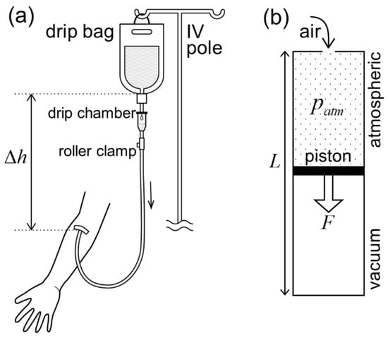
Figure 1.
Gravity versus atmospheric pressure as a driving force for drip infusion. (a) An IV drip bag hung from an IV pole at a constant height, , from a drip point on the arm maintains a constant infusion pressure to overcome the venous pressure. (b) Vacuum piston cylinder. A piston, with a cross-sectional area, , separating a sealed vacuum chamber and an open chamber under atmospheric pressure, , moves towards the closed end of the cylinder. The larger the diameter, , of the piston (cross-sectional area ), the larger the magnitude of the driving force, , on the piston. The length of the cylinder, , determines the moving stroke of the piston.
However, the gravity-driven method is imperfect: it confines a patient’s movement, causing stress, especially for patients routinely undergoing long hours of slow drip such as IV chemotherapy for oncology patients [27]. For hospitalized athletes, limiting their mobility may also affect their physical and mental rehabilitation [28]. On the other hand, elderly patients who move with a wheeled IV pole, for instance, to attend toileting needs, may risk an accidental fall, resulting in unintentional injuries [29]. These problems of gravity drip have motivated much effort to produce inventive and innovative drip devices such as shoulder-mounted drip poles [30,31,32,33], a neck-mountable IV bag design such as a U-shaped pillow [34], wearables for carrying battery-powered infusion pumps [35,36,37], and even an autonomous IV stand that can monitor a patient’s movement and move concurrently with the patient [38]. These studies provide solutions from different perspectives. Efforts in [30,31,32,33,38] focused on the IV pole, modifying it to become body-mountable [30,31,32] with automatic pole-balancing control [33], or sustaining the pole structure but causing it to move and follow the patient on its own [38]. The approach taken in [34,35,36,37] was to remove the IV pole and re-design the IV bag to make it attachable to the neck to gain gravity potential [34], or to maintain the current IV bag design but resort to battery-driven actuators for fluid delivery [35,36,37]. Echoing the motivation of these efforts, our aim was to find an alternative and sustainable solution by considering the following criteria: (i) trying to preserve the existing advantages of gravity drip which is easy to set up, electricity-free and highly affordable, (ii) placing priority on the stability of the infusion flow rate for treatment efficacy and patients’ safety, and (iii) emphasizing compatibility with existing IV bags and infusion tube sets. With these criteria, we strove to achieve a concept of electricity-free and non-hanging IV drip therapy that will enhance resilience in medical treatments, especially at evacuation shelters in disaster-hit areas or refugee camps in war-stricken regions.
In this work, we ventured into a novel approach in which we removed the IV pole but sustained the current design of the IV bag, and at the same time, sought a non-electric way to drive the infusion fluid. Our aim was to find an alternative driving force to gravity, design and test feasible pressurization mechanisms acting on an IV bag to transform the driving force into fluid pressure for fluid infusion, and find the best-performing pressurization mechanism for the infusion pump. As an alternative to gravitational force, for instance, a driving force can be derived from the pressure difference between a vacuum and the atmospheric pressure in a vacuum piston cylinder [39,40,41,42,43,44]. Another feasible option could be an elastic force exerted by a spring [45,46] or a bellows [47]. For the pressurization mechanism, viable approaches can generally be categorized into three options, namely, (a) pressing a rigid plate on a drip bag [43,45,46,47], (b) squeezing a drip bag by one or multiple rollers [48], and (c) compressing a drip bag by an inflating air bag [49,50,51,52]. However, it is unclear whether these mechanisms have been tested in terms of stability of infusion flow rate. First, we considered atmospheric pressure as a sustainable source of driving force on earth and, thus, an ideal alternative to gravity, leading us to employ the vacuum piston cylinder as the driving mechanism. Figure 1b presents a typical structure of a vacuum piston cylinder in which a piston separates a sealed vacuum chamber and an open atmospheric chamber. A driving force, derived from the pressure difference between the two chambers, acts towards the closed end of the cylinder. The magnitude and moving stroke of the resultant driving force are determined by the dimensions (i.e., diameter and length) of the cylinder. Second, we fabricated several novel and feasible prototypes combining one or multiple units of vacuum piston cylinder with each of the three pressurization mechanisms mentioned above. Third, to observe their potential in producing a stable infusion flow rate, we performed evaluation tests on the discharge flow rate from each prototype of infusion pump using a gravimetric test bench built for this purpose. Finally, a conclusion was drawn on the best pressurization mechanism, with prospects of future work.
2. Pressurization Mechanisms
We aimed to design an optimum pressurization mechanism acting on a drip bag, with the infusion pump producing a certain level of dosing stability and accuracy, in line with medical guidelines [53,54] and, ideally, comparable to the existing suspended drip system. In the succeeding sections, we discuss the problems and challenges faced in developing various pressurization mechanisms. At this early stage, design emphasis was placed more on prototype functionality rather than compactness and user-friendliness. Additionally, it should be noted that the outlet of the drip bag was orientated upwards in most of the prototypes for easy air-bleeding of the drip bag. Another noteworthy point is that all the infusion pump prototype designs were intended to be capable of generating a fluid pressure of approximately 15 kPa inside the drip bag, which is enough to overcome venous pressure.
2.1. Prototypes Using a Pressing Rigid Plate
A prototype (hereafter, V-PRESS) was fabricated, comprising a pressing plate orientated in a V-shaped layout against the housing wall (see Figure 2). The pressing mechanism was driven by a vacuum piston cylinder through a connecting structure. Theoretically, V-PRESS was designed to exert an increasing rotational momentum on the pressing plate as it moved towards the wall, with the aim of compensating the pressure (flow rate) drop during fluid infusion. However, measurements of the resulting fluid pressure from the drip bag did not result as expected, showing a significant pressure drop. The main reason for this was the change of contact surface area between the pressing plate and the drip bag as the mechanism moved. Placing an air bag between the pressing plate and the drip bag to improve the adherence of the contact surface did not solve the problem either. Figure 2c shows how to reset the pressing plate back to the original starting position.
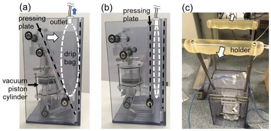
Figure 2.
Prototype V-PRESS. (a) A piston is at the starting position of cylinder. A pressing plate is at the standby position before moving towards the drip bag. (b) The piston is at the end position of cylinder. The pressing plate fully compresses the drip bag. (c) The pressing plate is reset to the starting position by pulling the two holders away from each other.
Meanwhile, we worked on another prototype, as shown in Figure 3. This prototype (hereafter, UP-PRESS) worked by elevating the pressing plate, using two vacuum piston cylinders, to exert pressure on the drip bag (see Figure 3a). This mechanism was thought to have the advantage of maintaining a more consistent contact area between the pressing plate and the drip bag. In Figure 3b, a stopper holds the pressing plate at the standby position before release. In Figure 3c, flipped-up handles allow the pressing plate to be pushed back to the standby position after operation.
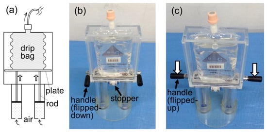
Figure 3.
Prototype UP-PRESS. (a) A pressing plate, elevated by the vacuum piston cylinders through rods, exerts pressure on the drip bag. (b) The pressing plate is held at the standby position by a stopper. (c) Handles can be flipped up for the pressing plate to be reset (pushed down) to the standby position.
2.2. Prototypes Using Squeezing Rollers
Another prototype (hereafter, MOVE-ROLLER) that worked by squeezing the drip bag using a pair of rollers, was also developed (see Figure 4). The rollers rotated themselves and squeezed a fixed-mounted drip bag while being pulled down by the vacuum piston cylinders (see Figure 4a,b). However, a problem arose in which the drip fluid escaped from the high-pressure side to the low-pressure side inside the drip bag, resulting in leakage through the small gap between the rollers (see Figure 4c,d).
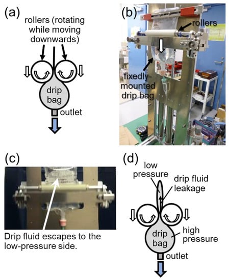
Figure 4.
Prototype MOVE-ROLLER. (a) Squeezing mechanism on a drip bag by a pair of rollers. (b) Operational testing of the mechanism. (c) Observation of drip fluid escape. (d) Schematic explanation of the drip fluid leakage occurring inside the drip bag.
To solve the problem faced by the MOVE-ROLLER, we developed a modified prototype (hereafter, FIX-ROLLER) as shown in Figure 5, in which a big roller was employed for the purpose of winding up the emptied part of the drip bag, thus, preventing the drip fluid escape encountered in MOVE-ROLLER. The opposite end of the drip bag outlet was attached to the big roller before operation. As shown in Figure 5a, a wire connected to a vacuum piston cylinder pulls and rotates the big roller, driving the whole mechanism. One should take note that, for simple representation, the movement of the piston (horizontally to the right) in Figure 5a differs from the actual movement, which is upwards in Figure 5c. Compared with MOVE-ROLLER, the new features in FIX-ROLLER included all rollers rotating at fixed positions, and the outlet of the drip bag facing upwards. Exterior and interior views of FIX-ROLLER are shown in Figure 5b,c, respectively. The rolling mechanism is unlocked for release in Figure 5d, and then reset back to the standby position in Figure 5e.
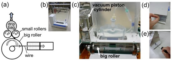
Figure 5.
Prototype FIX-ROLLER. (a) A vacuum piston cylinder, whose actual orientation (vertical position) is shown in (c), pulls and rotates a rolling mechanism by a wire. (b) An exterior view of the prototype. (c) An interior view of the prototype mounted with a drip bag. (d) The rolling mechanism is locked at the standby position by an interior-mounted rachet gear tooth (not visible in (c)). The rolling mechanism is unlocked by turning a toggle switch at the exterior side panel. (e) The rolling mechanism is reset to the standby position using a hexagonal wrench.
2.3. Prototypes Using Inflated Air Bags
To identify which shape of air bag performed best as a pressurization mechanism, we conducted a series of tests (Tests No. 1–3) as shown in Figure 6. Test No. 1 acted as an observatory test without using any air bag (see Figure 6a,b). In all tests, two parallel plates used for compression were loaded with dead weight to exert a constant force. A drip bag and air bags were filled with air. The air was released from the drip bag at a low flow rate controlled by a valve, while the air in the air bag was trapped by closing the valve. Pressures in the drip bag and the air bag were measured simultaneously.
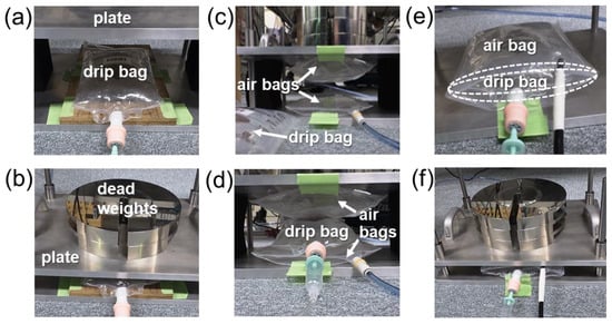
Figure 6.
(a,b): Test No. 1. A drip bag is placed between parallel plates with no air bag in (a), and then loaded with dead weight in (b). (c,d): Test No. 2. Two pillow-shaped air bags are placed between the parallel plates in (c), then a drip bag is inserted in between the two air bags, and the sandwiched drip bag is loaded with dead weight in (d). (e,f): Test No. 3. A drip bag is enwrapped in a sleeping-bag-shaped air bag in (e), and then loaded with dead weight in (f).
Test No. 1 showed the steady decreasing of the drip bag pressure that was normalized by the initial drip bag pressure, though under a constant force from the dead weight (see Figure 7a). This may have been due to the change of contact surface area between the plate and the drip bag as the drip bag deflated. The pressure value in the ordinate in Figure 7b,c was normalized by the initial air bag pressure. At the starting point in Test No. 2, the drip bag pressure was higher than the air bag pressure (see Figure 7b). This may be attributed to the surface tension occurring at both the curving (arc-like) side-surfaces of the drip bag which were not in contact with the air bags [55]. However, this did not happen in Test No. 3, in which the side-surfaces of the enwrapped drip bag were in contact with the sleeping-bag-shaped air bag (see Figure 7c). In both Tests No. 2 and No. 3, it can be observed that the air bag pressure decreased slightly due to the change of contact surface area with the plates as the air bags compressed the drip bag. Seeing that the pressures of both drip bag and air bag showed the best unison in Test No. 3 (see Figure 7c), we concluded that the sleeping-bag-shaped air bag (see Figure 6e) was the best inflating mechanism to pressurize the drip bag.

Figure 7.
Pressure measurement results of the tests shown in Figure 6. (a) Test No. 1. A drip bag only (see Figure 6a,b). (b) Test No. 2. A drip bag sandwiched between two pillow-shaped air bags (see Figure 6c,d). (c) Test No. 3. A drip bag enwrapped in a sleeping-bag-shaped air bag (see Figure 6e,f).
A prototype (hereafter, AIR-BAG) using the sleeping-bag-shaped air bag as the pressurizing mechanism was then developed (see Figure 8). To inflate the air bag, we designed a novel air-compressor mechanism that was driven by a vacuum piston cylinder. As shown in Figure 8a, a small piston with a cross-sectional area of in a vacuum piston cylinder (upper cylinder) pushes a large piston with a cross-sectional area of through a connecting rod in an air piston cylinder (bottom cylinder), resulting in compressed air being supplied to an inflating air bag enwrapping a drip bag. The pressure of the compressed air, , (gauge pressure) can be approximately estimated as where is the atmospheric pressure. Figure 8b shows the actual fabrication of the prototype with a transparent interior view. To push the vacuum and air pistons back to the starting position, a hand-operated inflator was used to pump air into the compressed air chamber of the air piston cylinder (see Figure 8c).
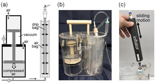
Figure 8.
Prototype AIR-BAG. (a) Pressurizing mechanism acting on a drip bag comprises a vacuum piston cylinder built together with an air piston cylinder, and a sleeping-bag-shaped air bag in a separate compartment. (b) A transparent view of the prototype’s interior. (c) A hand-operated inflator with sliding motion is used to pump air into the compressed air chamber shown in (a), to push both the vacuum and air pistons back to the starting (standby) position.
3. Evaluation of Flow Performance
As one of the criteria of being a possible alternative to the gravity-driven infusion method, the atmospheric pressure-driven method needs to achieve a dosing stability level comparable to the gravity method. Medical guidelines [53,54] also recommend that the flow rate accuracy for non-electrically driven infusion devices be within ±20% of the nominal flow rate. To conduct measurements of the discharge flow rate from the prototypes, we built a gravimetric test bench, which is discussed in the following section.
3.1. Gravimetric Test Bench
As shown in Figure 9a, a gravimetric (weighing) test bench was enclosed by a wind shield to avoid any wind effect. A pneumatically liftable stage supported a weighing balance at a variable height for flow rate measurement at different head pressures. Figure 9b shows a specially designed weighing vessel sitting on a weighing plate. The weighing range of the weighing balance was up to 6 kg, with a resolution of 0.01 g. As shown in Figure 9c, the weighing vessel had a special feature, in which an inner vessel stood on the bottom surface of the weighing vessel. One method of avoiding liquid dropping from the tube into the weighing vessel could be to immerse the tube into the liquid, but this would create immersion effects, such as a buoyancy effect, of the immersed tube beneath the rising liquid level. To maintain a constant immersed depth of the tube, many studies have adopted an overflowing inner vessel where a tube or a needle is immersed into the overflowing inner vessel [56,57,58,59]. Another method could be to maintain a constant liquid bridge or stream connecting the tube outlet and a liquid-absorbing material, such as glass filter or foam mounted inside a weighing vessel [60]. For liquid collection in this study, we combined the two methods, by not overflowing the inner vessel but filling it with liquid-absorbing spongy material so that the liquid stream from the tube outlet was absorbed. Liquid then wove through the sponge, down the inner vessel, and flowed out from the openings at the bottom of the inner vessel (see Figure 9c).
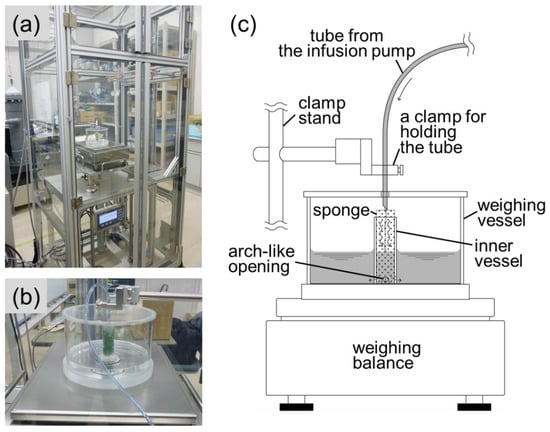
Figure 9.
Gravimetric test bench for flow rate measurement. (a) A weighing balance sits on a liftable stage inside a wind shield enclosure. (b) A specially designed weighing vessel sits on a weighing plate. (c) Features of the weighing vessel.
The dynamic weighing method was adopted for the test bench, in which the increasing liquid mass collected inside the weighing vessel was measured by the weighing balance as a function of time, to ultimately obtain the mass flow rate. The flow rate was determined by a simple ratio of the differences in mass and time over a time interval. Though fitting methods such as linear fit over a time window will give a smoother curve with reduced noise, we considered that the noise was not so significant in the gravimetric system, and the present calculation method was good enough to see the flow performance of the infusion pump prototypes. Taking into consideration uncertainty factors such as liquid evaporation, resolution of weighing balance, buoyancy effect and so on, we performed a preliminary uncertainty analysis of the test bench, obtaining an expanded uncertainty of about 3.3% for the smallest flow rate of 3.0 g/min. The dominant uncertainty factor in the flow rate determination was the resolution of the weighing balance. Nevertheless, the amplitude order of the measurement uncertainty (3.3%) was considered sufficient in the context of the present study, seeing that the flow rate accuracy requirement for non-electrically driven infusion pumps is ±20%.
3.2. Tests of Flow Performance
Using the test bench described in Section 3.1, tests of flow performance were conducted on three feasible prototypes, namely: a. UP-PRESS, b. FIX-ROLLER and c. AIR-BAG, of which the measurement results are shown in Figure 10a–c. The left ordinate corresponds to the discharge flow rate, whereas the right ordinate corresponds to the amount of discharged liquid. In the performance test, liquid was discharged from drip bags with 500 mL content over a time period of about 2 to 3 h, at a flow rate adjusted between 3 and 4 g/min. Apparently, prototype AIR-BAG (see Figure 10c) showed a relatively high flow stability, compared with prototypes UP-PRESS and FIX-ROLLER (see Figure 10a,b). In terms of flow variation, UP-PRESS showed a relatively large up-and-down, while FIX-ROLLER demonstrated small zigzagging of flow fluctuation. In a general sense, the inconsistent contact surface interaction between the pressurization mechanism and the drip bag in the two prototypes accounted for these flow behaviors.
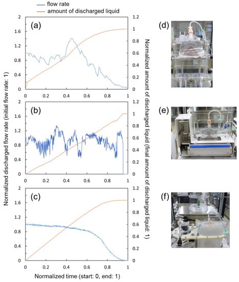
Figure 10.
Flow rate measurement results of the prototypes. (a) Prototype UP-PRESS. (b) Prototype FIX-ROLLER. (c) Prototype AIR-BAG. (d–f) Pictures of prototypes under tests corresponding to (a–c).
4. Discussion
In the previous section, we observed that the AIR-BAG prototype showed the most promising performance in terms of flow rate stability. To see how AIR-BAG compared with the existing gravity-driven method (pole-suspended drip system), we plotted the flow measurement results obtained for both methods in Figure 11. The left and right ordinates correspond to the discharge flow rate and the amount of discharged liquid, respectively, whereas the abscissa shows the measurement time. All quantities were represented in normalized and non-dimensional values to ease comparison. To avoid curves’ overlapping that may cause confusion, only part of the curves (in orange and yellow) for the amounts of discharged liquid are shown in Figure 11.
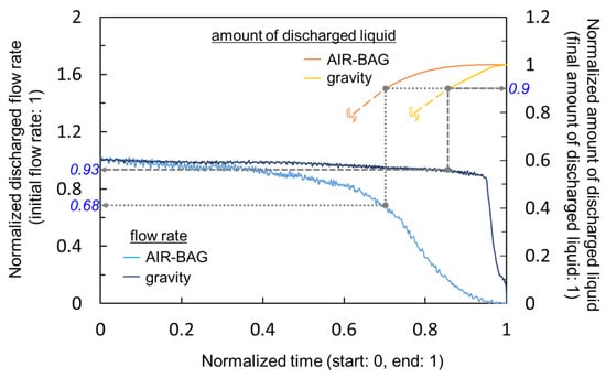
Figure 11.
Comparison of the infusion flow rate stability between the prototype AIR-BAG and the existing gravity-driven method.
Overall, as demonstrated in Figure 11, the discharge flow rate of the AIR-BAG decreased faster over the time span of measurement, than the gravity method. As a comparison index, we chose the value 0.9 (or 90%) in terms of the amount of discharged liquid in the right ordinate and traced it to the corresponding discharge flow rates in the left ordinate (see dotted and dashed grey lines in Figure 11). When 90% of the amount of liquid was discharged from the drip bag, the flow rates infused by the AIR-BAG and the gravity decreased to 0.68 (68%) and 0.93 (93%), respectively, of the initial flow rates. In other words, during the majority (up to 90%) of the infusion process, the gravity drip method maintained a consistent level, in terms of flow rate, that was a maximum of 25% better than the AIR-BAG prototype. This prompted us to launch investigatory work into the next phase of study, to find ways to improve the AIR-BAG. Other than flow performance, much work has still to be conducted on developing the portability and ergonomics of the design. It should also be noted that the performance index described above had a scatter of approximately 10% in terms of the difference between the maximum and minimum values from the repeated measurements.
Of note, the flow rates were adjusted by using the roller clamp and by monitoring the liquid drops in the drip chamber of the infusion tube set (see Figure 1a), which made it difficult to accurately adjust the flow rate. This resulted in certain discrepancies in flow rates between measurement runs. It may appear incomprehensible to observe that a quickly decreasing flow rate from the AIR-BAG (blue curve in Figure 11) produced a higher amount of discharged liquid (orange curve in Figure 11) than the highly consistent flow rate by the gravity method. This occurred because the actual (non-normalized) flow rate of AIR-BAG was slightly higher than that of the gravity method, resulting in a faster accumulation of discharged liquid in the weighing vessel.
The limitation of the infusion pump mechanism proposed in this study in general, as well as the limitation of the flow performance results discussed in the present context specifically, should also be noted. Since atmospheric pressure is the source of the driving force for the pressurization mechanism, the device performance is expected to vary with different altitudes; the difference may be especially significant between sea level and highlands or in an air ambulance or airplane. It is possible that thinner air will lower the maximum infusion flow rate of the infusion pump. This may require the need to devise ‘infusion pump models for high-altitude use’ in the future.
5. Summary and Conclusions
As a potential alternative to the gravity-driven infusion method, several prototypes based on three different pressurization mechanisms driven by a vacuum piston cylinder were designed and fabricated. The performance of three feasible prototypes, in terms of flow rate stability, were tested using a gravimetric test bench. Prototype AIR-BAG showed the most promising result in terms of flow stability compared with prototypes UP-PRESS and FIX-ROLLER. In the future, we will continue working on AIR-BAG to enhance its performance to a level comparable with the gravity-driven method.
6. Patents
Some of the infusion pump prototypes described in this paper are patent pending.
Author Contributions
Conceptualization, methodology, K.-H.C., R.D. and M.N.; software, K.-H.C. and R.D.; investigation, formal analysis, K.-H.C., R.D., M.N. and R.K.; resources, K.K., T.A., Y.O. and T.K.; validation, data curation, N.F. and Y.K.; writing—original draft preparation, K.-H.C.; writing—review and editing, R.D., N.F. and Y.K.; supervision, N.F. and Y.K.; project administration, funding acquisition, M.N. and K.-H.C. All authors have read and agreed to the published version of the manuscript.
Funding
This work was supported by the Japanese Ministry of Economy, Trade and Industry through the Project for Supporting Industry in Strategic Enhancement of Fundamental Technology FY2018-2019.
Institutional Review Board Statement
Not applicable.
Informed Consent Statement
Not applicable.
Data Availability Statement
Data available on request due to restrictions of patent pending.
Acknowledgments
Yoshiyuki Watanabe of Kawasaki Rinko Hospital is acknowledged for his opinions and comments on this study.
Conflicts of Interest
The authors declare no conflict of interest.
References
- Martin-Schild, S.; Morales, M.M.; Khaja, A.M.; Barreto, A.D.; Hallevi, H.; Abraham, A.; Sline, R.; Johns, E.; Grotta, J.C.; Savitz, S.I. Is the drip-and-ship approach to delivering thrombolysis for acute ischemic stroke safe? J. Emerg. Med. 2011, 41, 135–141. [Google Scholar] [CrossRef] [PubMed]
- Goltser, A.; Soleyman-Zomalan, E.; Kresch, F.; Motov, S. Short (low-dose) ketamine infusion for managing acute pain in the ED: Case-report series. Am. J. Emerg. Med. 2015, 33, 601.e5–601.e7. [Google Scholar] [CrossRef] [PubMed]
- Millin, M.G.; Kim, S.; Schmidt, T.A.; Daya, M.R.; Fujisaki, B. Intermittent bolus dosing of lidocaine in emergency medical services—An alternative to bolus followed by a drip. Prehospital Emerg. Care 2006, 10, 403–408. [Google Scholar] [CrossRef] [PubMed]
- Dunphy, K.; Finlay, I.; Rathbone, G.; Gilbert, J.; Hicks, F. Rehydration in palliative and terminal care—If not why not. Palliat. Med. 1995, 9, 221–228. [Google Scholar] [CrossRef] [PubMed]
- Letson, H.L.; Dobson, G.P. 3% NaCl adenosine, lidocaine, Mg2+ (ALM) bolus and 4 hours drip infusion reduces noncompressible hemorrhage by 60% in a rat model. J. Trauma Acute Care Surg. 2017, 82, 1063–1072. [Google Scholar] [CrossRef]
- Kumagai, M.; Yamashita, M. Sacral intervertebral approach for epidural-anesthesia in infants and children—Application of drip and tube method. Anaesth. Intensive Care 1995, 23, 469–471. [Google Scholar] [CrossRef]
- Ayulo, M.A.J.; Phillips, K.E.; Tripathi, S. Safety and efficacy of IV lidocaine in the treatment of children and adolescents with status migraine. Pediatric Crit. Care Med. 2018, 19, 755–759. [Google Scholar] [CrossRef]
- Menahem, S.; Shvartzman, P. Continuous subcutaneous delivery of medications for home care palliative patients-using an infusion set or a pump? Supportive Care Cancer 2010, 18, 1165–1170. [Google Scholar] [CrossRef]
- Kodama, M.; Oyama, A.; Takagi, H. Control of interstitial pneumonia by drip infusion of megadose vitamin C, dehydroepiandrosterone and cortisol. A short review of our experience. In Vivo 2008, 22, 263–267. [Google Scholar]
- Gaby, A.R. Intravenous nutrient therapy: The “Myers’ Cocktail”. Altern. Med. Rev. 2002, 7, 389–403. [Google Scholar]
- Fulcher, E.M.; Frazier, M.S. Introduction to Intravenous Therapy for Health Professionals; Saunders/Elsevier: New York, NY, USA, 2007; pp. 2–4. [Google Scholar]
- Ausman, R.K. Intravascular Infusion Systems: Principles and Practice; Springer: Berlin/Heidelberg, Germany, 1984; pp. 9–13. [Google Scholar]
- Blundell, J. Observations on transfusion of blood. Lancet 1829, 2, 302. [Google Scholar] [CrossRef]
- Latta, T. Note from Dr. Latta. Lancet 1832, 18, 640. [Google Scholar] [CrossRef]
- Latta, T. Saline venous injection in cases of malignant cholera, performed while in the vapour-bath. Lancet 1832, 19, 173–176. [Google Scholar] [CrossRef]
- Watkins, K.H. A note on pre-operative preparation of cases with grave intra-abdominal haemorrhages. Br. Med. J. 1935, 1, 52–54. [Google Scholar] [CrossRef] [PubMed][Green Version]
- Oros, D.; Penčić, M.; Šulc, J.; Čavić, M.; Stankovski, S.; Ostojić, G.; Ivanov, O. Smart intravenous infusion dosing system. Appl. Sci. 2021, 11, 513. [Google Scholar] [CrossRef]
- Pratim, R.P.; Thapa, N. A systematic review on real-time automated measurement of IV fluid level: Status and challenges. Measurement 2018, 129, 343–348. [Google Scholar]
- Cataldo, A.; Cannazza, G.; Giaquinto, N.; Trotta, A.; Andria, G. Microwave TDR for real-time control of intravenous drip infusions. IEEE Trans. Instrum. Meas. 2012, 61, 1866–1873. [Google Scholar] [CrossRef]
- Shimohira, C.; Hasegawa, Y.; Taniguchi, K.; Matsushima, M.; Kawabe, T.; Shikida, M. Development of micromachined flow sensor for drip infusion system. Microsyst. Technol. 2020, 26, 3677–3683. [Google Scholar] [CrossRef]
- Norgia, M.; Magnani, A.; Melchionni, D.; Pesatori, A. Drop measurement system for biomedical application. IEEE Trans. Instrum. Meas. 2015, 64, 2513–2517. [Google Scholar] [CrossRef]
- Volkov, I.V.; Zayarnyi, V.P.; Makarov, A.M.; Kobzev, N.V. Contactless measurement of low liquid flow rates. Meas. Tech. 2014, 57, 783–786. [Google Scholar] [CrossRef]
- Raghavendra, R.K.; Evangili, S.K. Design and development of IoT based intravenous infusion system. In Emerging Trends in Electrical, Communications, and Information Technologies: ICECIT 2018; Hitendra, S.T., Sankar, V., Shaik, R., Eds.; Springer: Singapore, 2020; Volume 569, pp. 487–499. [Google Scholar]
- Dinesh, K.J.R.; Ganesh, B.C.; Soundari, D.V.; Priyadharsini, K.; Karthi, S.P. A novel system design for intravenous infusion system monitoring for betterment of health monitoring system using ML-AI. Int. J. Innov. Technol. Explor. Eng. 2020, 9, 2649–2655. [Google Scholar]
- Chen, C.-L.; Hsieh, N.-C.; Hung, L.-P. Developing a wireless based dynamic management mechanism for intravenous drip scheduling. Int. J. Ad Hoc Ubiquitous Comput. 2015, 19, 208–220. [Google Scholar] [CrossRef]
- Ting, S.-H.; Wu, C.-K.; Luo, C.-H. Design of dual mode RFID antenna for inventory management and IV fluid level warning system. Int. J. Antennas Propag. 2017, 2017, 2470291. [Google Scholar] [CrossRef]
- Skeel, R.T. Handbook of Cancer Chemotherapy, 6th ed.; Lippincott Williams & Wilkins: Philadelphia, PA, USA, 2003; p. 46. [Google Scholar]
- Podlog, L.; Dimmock, J.; Miller, J. A review of return to sport concerns following injury rehabilitation: Practitioner strategies for enhancing recovery outcomes. Phys. Ther. Sport 2011, 12, 36–42. [Google Scholar] [CrossRef] [PubMed]
- Moreland, B.; Kakara, R.; Henry, A. Trends in nonfatal falls and fall-related injuries among adults aged ≥65 years—United States, 2012–2018. CDC Morb. Mortal. Wkly. Rep. MMWR 2020, 69, 875–881. [Google Scholar] [CrossRef]
- Akiyama, A.; Yokouchi, K. Portable Instillation Apparatus and Method of Replenishing Instillation Solution in Instillation Container Portable Apparatus. Japan Patent JP2005246037A, 15 September 2005. [Google Scholar]
- Xu, W.-X. Shoulder-Mountable Intravenous Drip Pole. Chinese Patent TWM360702U, 11 July 2009. [Google Scholar]
- EZ Pole. Available online: https://www.red-dot.org/project/ez-pole-27529 (accessed on 9 March 2022).
- Wu, M.-F.; Chen, C.-S.; Chen, I.-S.; Kuo, T.-H.; Wen, C.-Y.; Sethares, W.A. Design of carryable intravenous drip frame with automatic balancing. Sensors 2020, 20, 793. [Google Scholar] [CrossRef]
- Nu-Drip. Available online: https://www.designboom.com/project/nu-drip/ (accessed on 9 March 2022).
- IV-Walk. Available online: https://www.alissarees.com/2017/02/iv-walk/ (accessed on 10 March 2022).
- IVWear. Available online: https://campus.groningen.nl/en/news/ivwear-takes-wearable-infusion-to-market (accessed on 10 March 2022).
- Ivy Duo+. Available online: https://www.ivymedical.nl/ (accessed on 10 March 2022).
- Sayed-Kassem, A.; Kozah, N.; Hajj-Moussa, G.; Harb, R.; Zaylaa, A.J. BMIVPOT, a fully automated version of the intravenous pole: Simulation, design, and evaluation. J. Healthc. Eng. 2020, 2020, 7963497. [Google Scholar] [CrossRef]
- Derlien, M.L.C. Apparatus for Delivering Fluids with Controlled Rates of Flow. U.S. Patent US4180067A, 25 December 1979. [Google Scholar]
- Mitchell, R.J. Vacuum Infusion Device. WIPO Patent WO1991016093A1, 31 October 1991. [Google Scholar]
- Yamada, K.; Yamanaka, J. Liquid Injection Device. WIPO Patent WO1995028977A1, 2 November 1995. [Google Scholar]
- Minezaki, S. Continuous Liquid Medicine Injector. Japan Patent JP2001333980A, 4 December 2001. [Google Scholar]
- Nakagawa, M.; Nobuyasu, Y.; Okada, M.; Watanabe, Y. Liquid Supply Device. WIPO Patent WO2017134737A1, 10 August 2017. [Google Scholar]
- Nakagawa, M.; Iwasaki, U.; Watanabe, Y. Liquid Supply System. Japan Patent JP6298208B1, 20 March 2018. [Google Scholar]
- Sakamoto, K. Liquid Chemical Injection Device. Japan Patent JPH09248337A, 22 September 1997. [Google Scholar]
- Lin, S.-L.; Lin, Y.-Y.; Lin, T.-Y. Portable Infusion Device. Chinese Patent TW201639602A, 16 November 2016. [Google Scholar]
- Suefuji, K. Portable Intravenous Drip Device. Japan Patent JP2018068919A, 10 May 2018. [Google Scholar]
- Arita, E.; Ooyanai, T. Infusion Device for Liquid Medicine. Japan Patent JPH09262290A, 7 October 1997. [Google Scholar]
- Kushishitamachi, J.; Ariizumi, K. Extrusion Apparatus for Medical Liquid and Method for It. Japan Patent JPH05337177A, 21 December 1993. [Google Scholar]
- Kano, C.; Hiroura, M. Infusion Bag Pressurizing Apparatus. Japan Patent JP2004230032A, 19 August 2004. [Google Scholar]
- Yuki, T.; Harada, M.; Ito, N. Push-Out Device. Japan Patent JP2011019709A, 3 February 2011. [Google Scholar]
- Suefuji, K. Portable Intravenous Drip Device. Japan Patent JP2016182329A, 20 October 2016. [Google Scholar]
- ISO 28620; International Standard for Medical Devices—Non-Electrically Driven Portable Infusion Devices. ISO: Geneva, Switzerland, 2020.
- Japan Ministry of Health, Labor and Welfare. Revision of Approval Criteria for Pressurized Drug Infusion Devices by Japan Ministry of Health, Labor and Welfare; No. 0201-13; Japan Ministry of Health, Labor and Welfare: Tokyo, Japan, 2018. (In Japanese)
- Hudson, J.B. Surface Science, An Introduction; John Wiley & Sons: Hoboken, NJ, USA, 1998. [Google Scholar]
- Su, C.-M.; Lin, W.-T.; Yang, C.-T. Flow calibration system for micro-flowrate delivery and measurement. In Proceedings of the NCSL International Workshop and Symposium, National Harbor, MD, USA, 21–25 January 2008. [Google Scholar]
- Claus, M.; Ulrich, K.; John, F. Design considerations and initial validation of a liquid microflow calibration setup using parallel operated syringe pumps. Meas. Sci. Technol. 2010, 21, 074004. [Google Scholar]
- Doihara, R.; Shimada, T.; Cheong, K.-H.; Terao, Y. Liquid low-flow calibration rig using syringe pump and weighing tank system. Flow Meas. Instrum. 2016, 50, 90–101. [Google Scholar] [CrossRef]
- Cheong, K.-H.; Doihara, R.; Shimada, T.; Terao, Y. Gravimetric system using high-speed double switching valves for low liquid flow rates. Meas. Sci. Technol. 2018, 29, 075304. [Google Scholar] [CrossRef]
- Bissig, H.; Tschannen, M.; de Huu, M. Micro flow facility for traceability in steady, pulsating flow. Flow Meas. Instrum. 2015, 44, 34–42. [Google Scholar] [CrossRef]
Publisher’s Note: MDPI stays neutral with regard to jurisdictional claims in published maps and institutional affiliations. |
© 2022 by the authors. Licensee MDPI, Basel, Switzerland. This article is an open access article distributed under the terms and conditions of the Creative Commons Attribution (CC BY) license (https://creativecommons.org/licenses/by/4.0/).