
Enhancement of Vibration Energy Harvesting Performance by Omni-Directional INVELOX Wind Funnel: A Computational Study


Abstract
:1. Introduction
2. Methodology
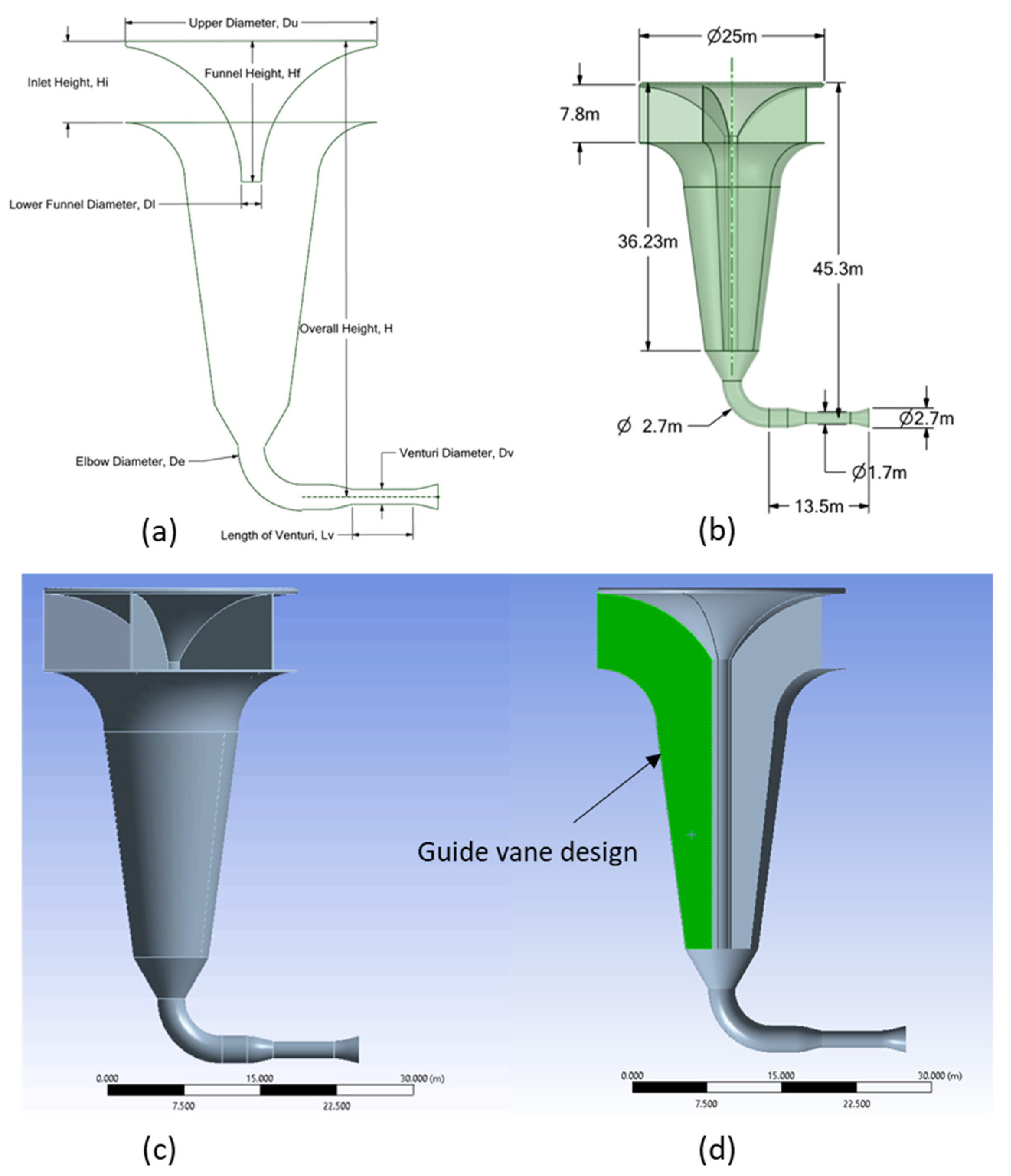
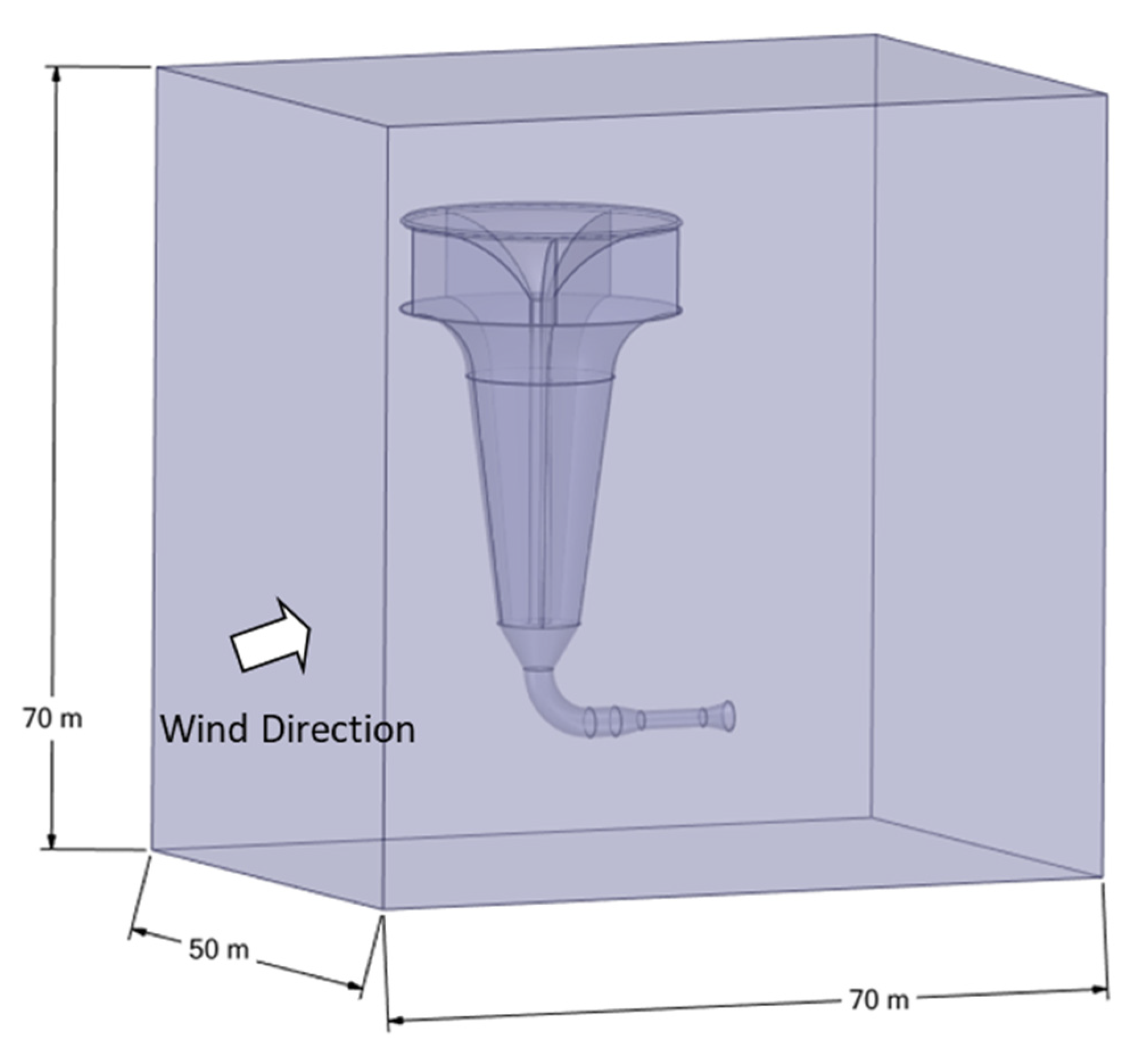
2.1. New Omni-Directional Wind-Funnel Design
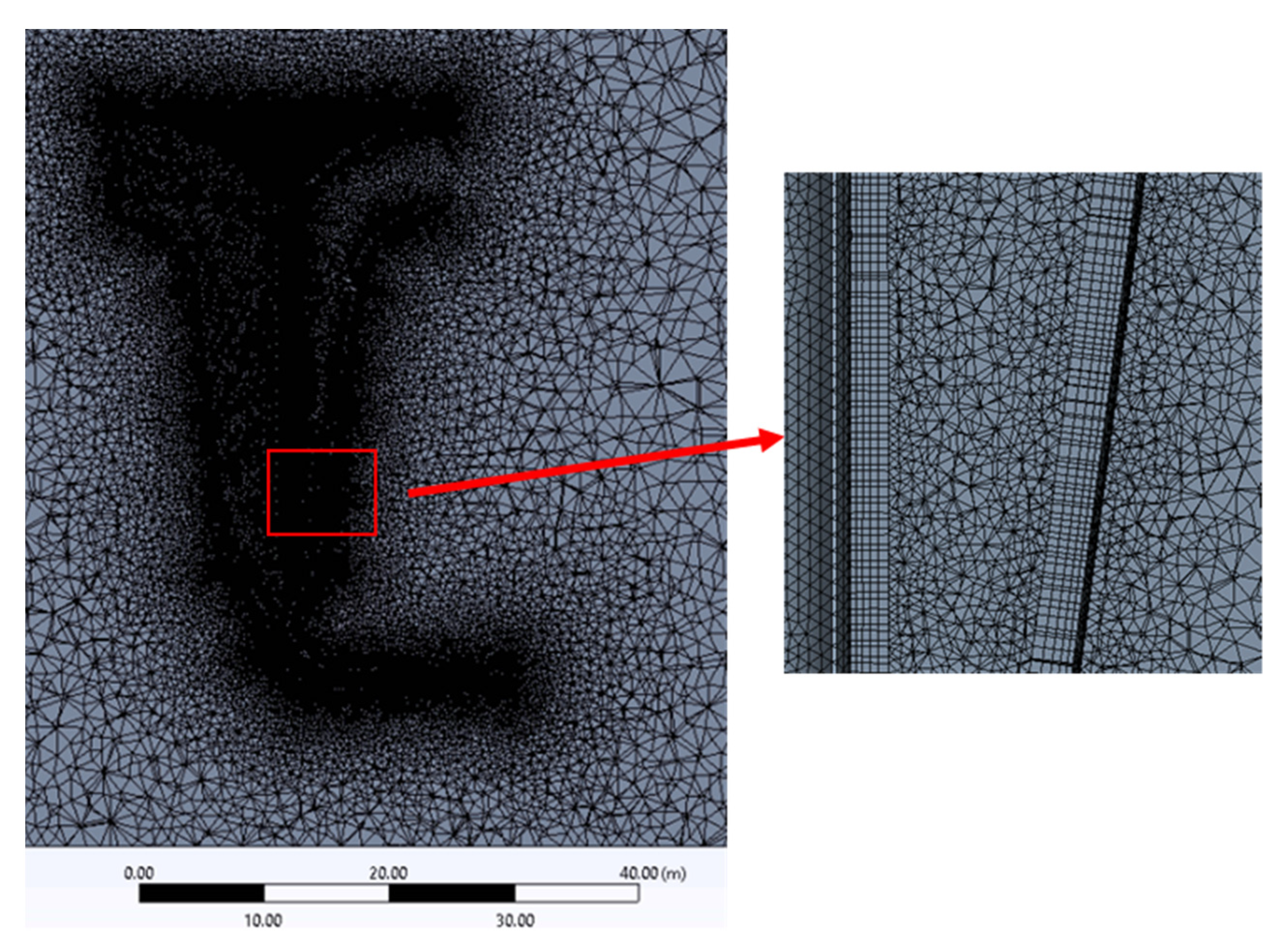
2.2. Numerical Model
2.2.1. Governing Equations
2.2.2. Turbulence Model
2.2.3. Solution Procedure
3. Results and Discussions
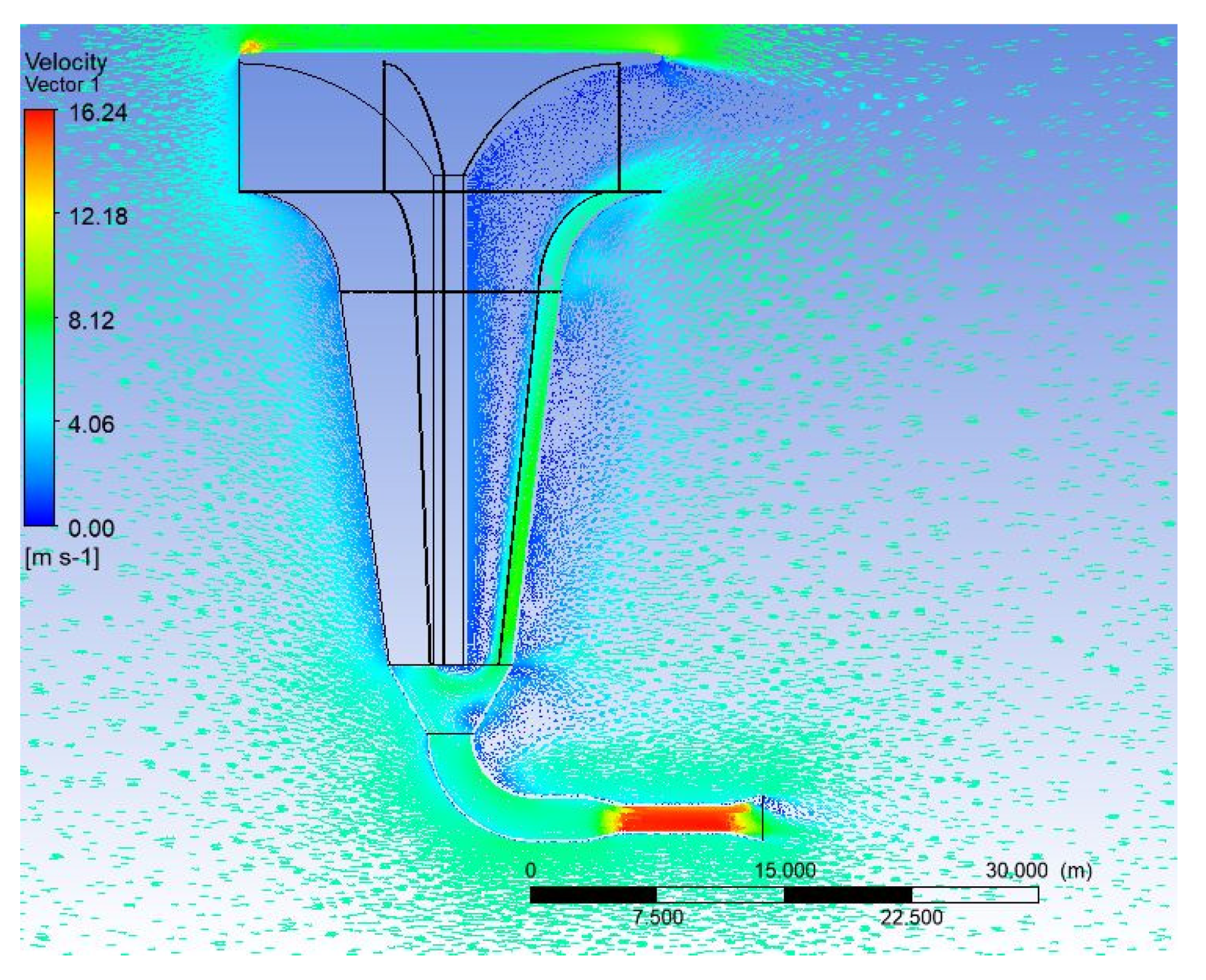
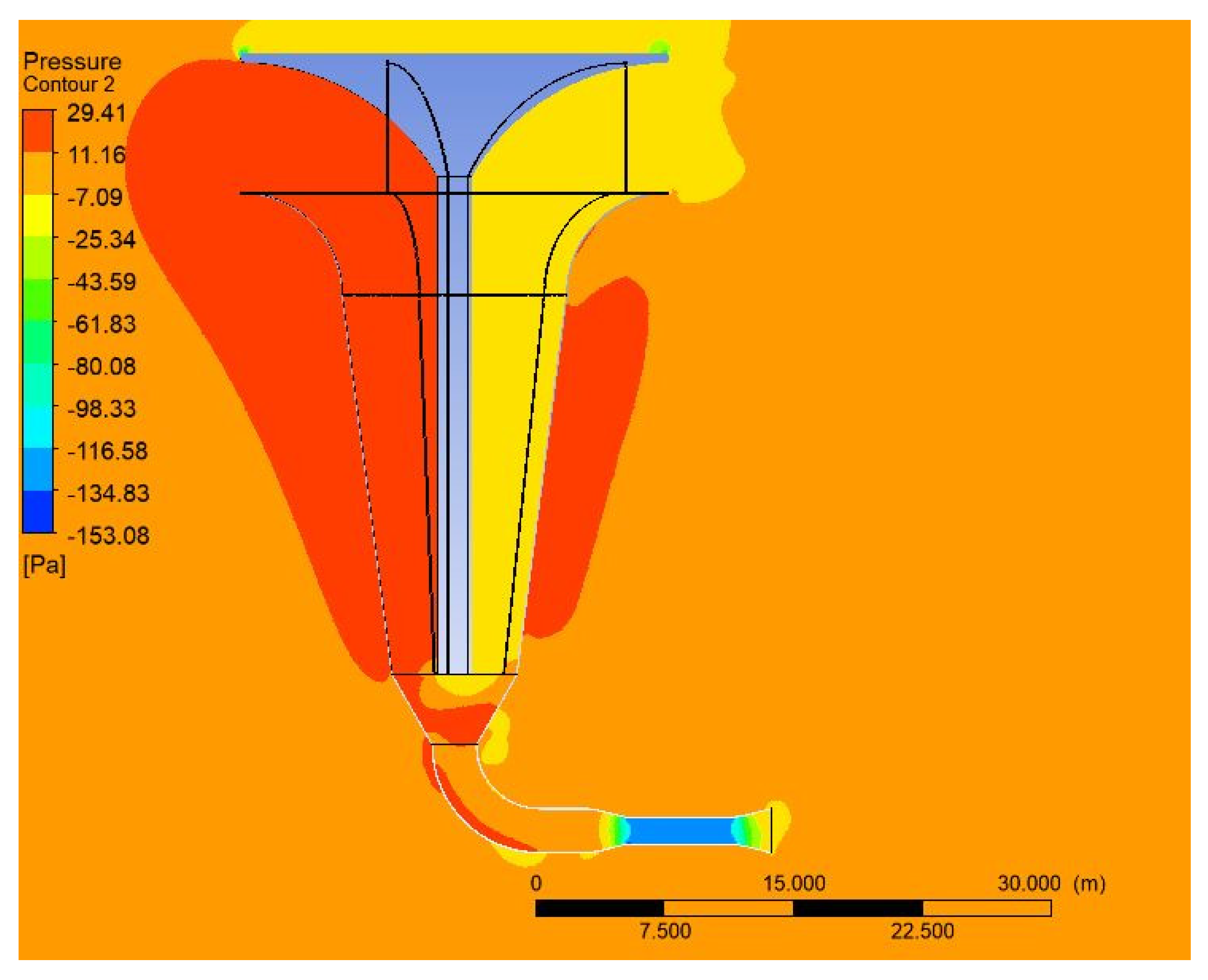
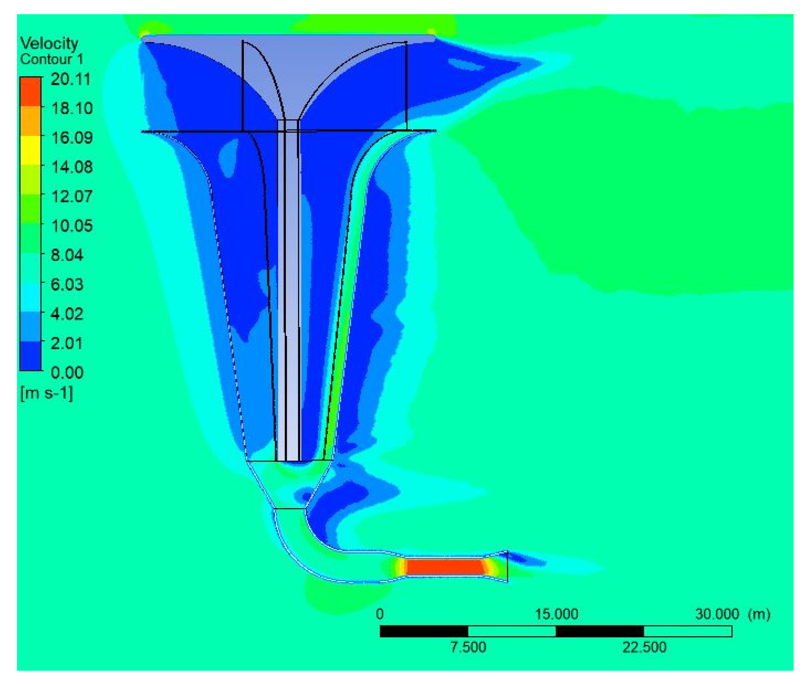
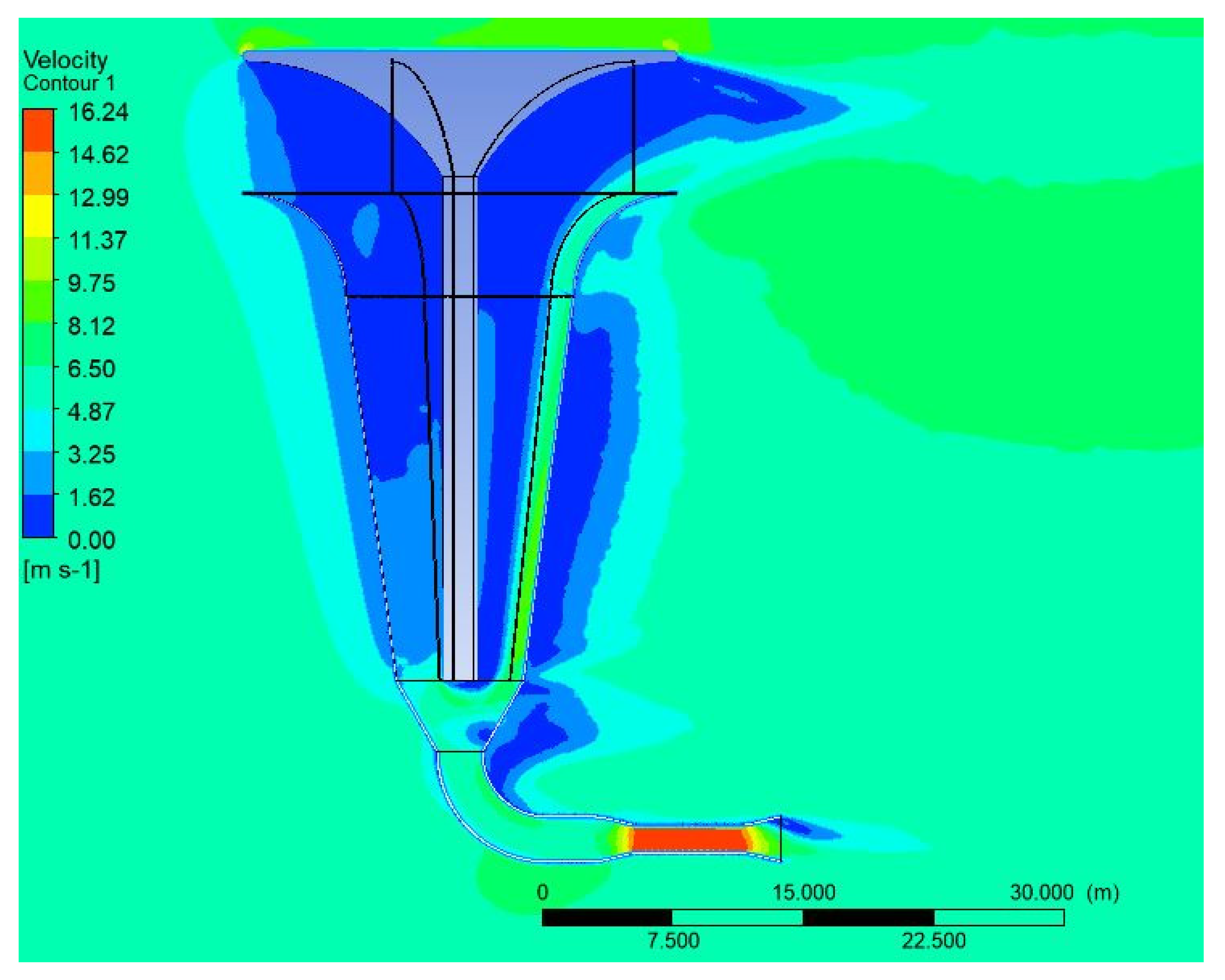
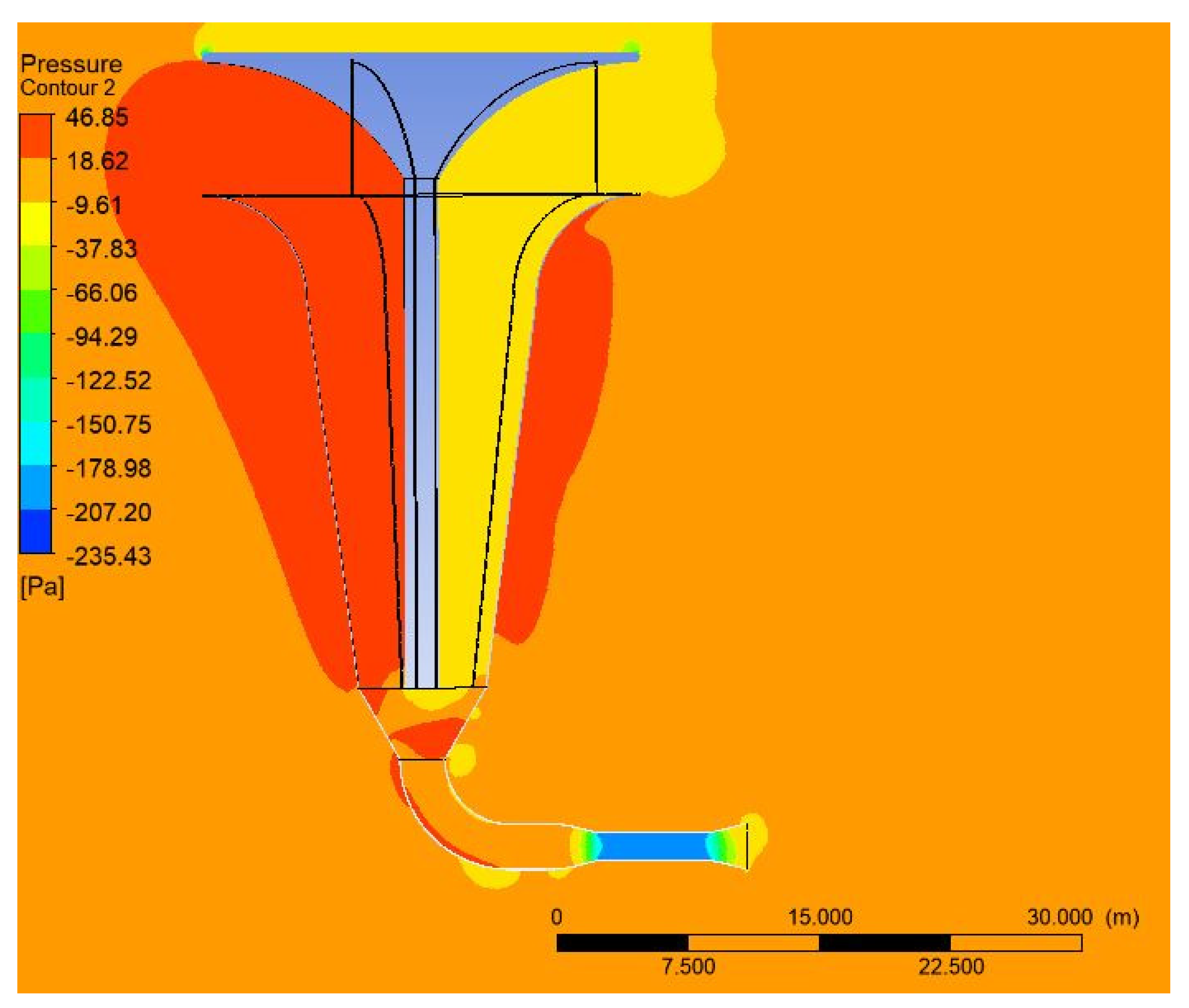
3.1. Performance of New Omni-Directional Wind-Funnel Design
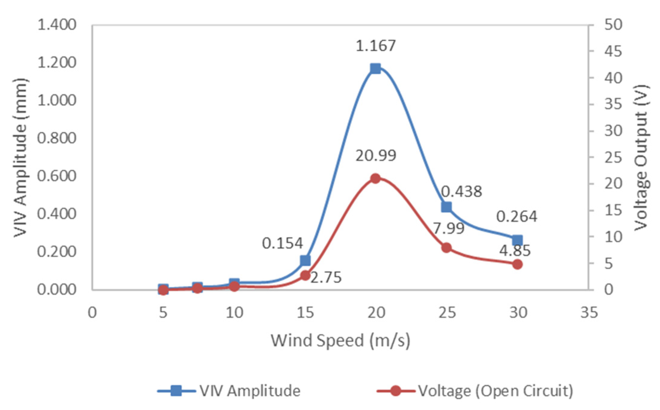
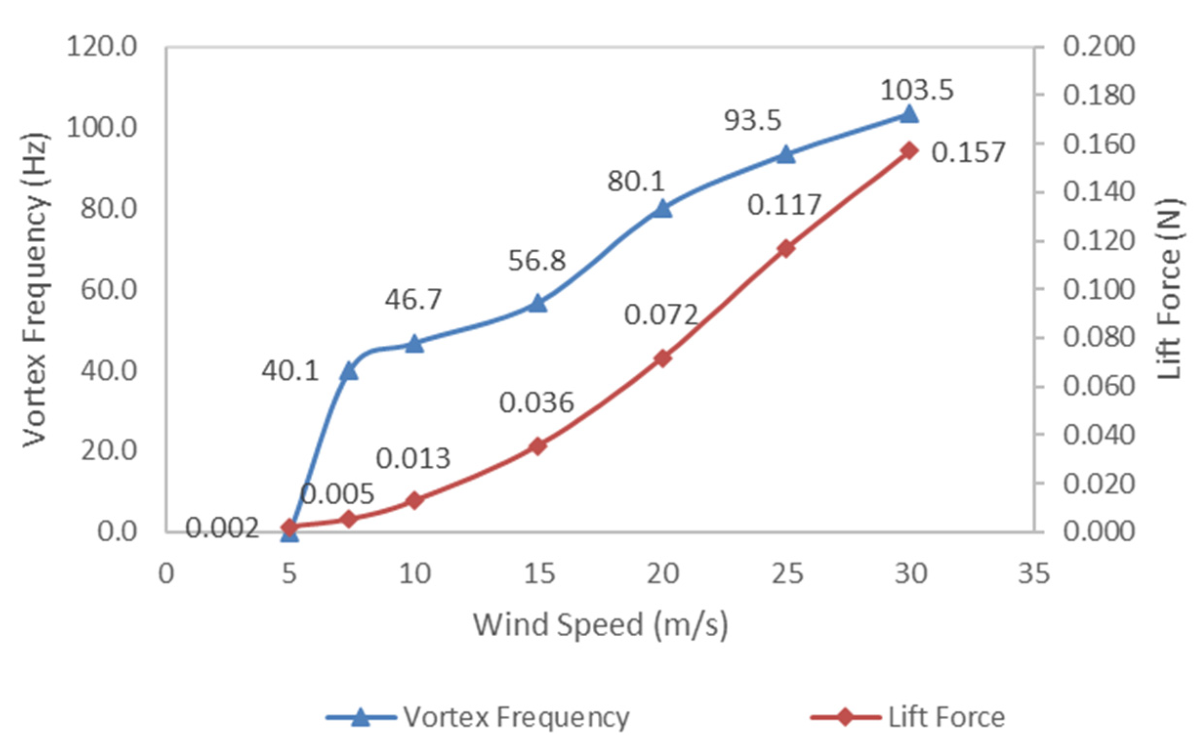
3.2. Performance of Vibration Energy Harvester Located at Its Venturi Throat of New Omni-Directional Wind-Funnel Design
4. Conclusions
Author Contributions
Funding
Acknowledgments
Conflicts of Interest
References
- Energy Commission, Energy Malaysia: Towards A World Class Energy Sector. Available online: https://www.st.gov.my/en/general/add_counter/851/download/read_count (accessed on 26 July 2022).
- Energy Commission, Annual Report 2020. Available online: https://www.st.gov.my/en/general/add_counter/848/download/read_count (accessed on 26 July 2022).
- Oh, T.H.; Pang, S.Y.; Chua, S.C. Energy policy and alternative energy in Malaysia: Issues and challenges for sustainable growth. Renew. Sustain. Energy Rev. 2010, 14, 1241–1252. [Google Scholar] [CrossRef]
- Irwanto, M.; Gomesh, N.; Mamat, M.; Yusoff, Y. Assessment of wind power generation potential in Perlis, Malaysia. Renew. Sustain. Energy Rev. 2014, 38, 296–308. [Google Scholar] [CrossRef]
- Siti, M.R.; Norizah, M.; Syafrudin, M. The Evaluation of Wind Energy Potential in Peninsular Malaysia. Int. J. Chem. Environ. Eng. 2011, 2, 284–291. [Google Scholar]
- Akorede, M.F.; Mohd Rashid, M.I.; Sulaiman, M.H.; Mohamed, N.B.; Ab Ghani, S.B. Appraising the viability of wind energy conversion system in the Peninsular Malaysia. Energy Convers. Manag. 2013, 76, 801–810. [Google Scholar] [CrossRef]
- Chin, W.K.; Ong, Z.C.; Kong, K.K.; Khoo, S.Y.; Huang, Y.-H.; Chong, W.T. Enhancement of Energy Harvesting Performance by a Coupled Bluff Splitter Body and PVEH Plate through Vortex Induced Vibration near Resonance. Appl. Sci. 2017, 7, 921. [Google Scholar] [CrossRef]
- Allaei, D.; Andreopoulos, Y. INVELOX: Description of a new concept in wind power and its performance evaluation. Energy 2014, 69, 336–344. [Google Scholar] [CrossRef]
- Anbarsooz, M.; Hesam, M.S.; Moetakef-Imani, B. Numerical study on the geometrical parameters affecting the aerodynamic performance of Invelox. IET Renew. Power Gener. 2017, 11, 791–798. [Google Scholar] [CrossRef]
- Anbarsooz, M.; Amiri, M.; Rashidi, I. A novel curtain design to enhance the aerodynamic performance of Invelox: A steady-RANS numerical simulation. Energy 2019, 168, 207–221. [Google Scholar] [CrossRef]
- Gohar, G.A.; Manzoor, T.; Ahmad, A.; Hameed, Z.; Saleem, F.; Ahmad, I.; Sattar, A.; Arshad, A. Design and comparative analysis of an INVELOX wind power generation system for multiple wind turbines through computational fluid dynamics. Adv. Mech. Eng. 2019, 11, 1687814019831475. [Google Scholar] [CrossRef]
- Sotoudeh, F.; Kamali, R.; Mousavi, S.M. Field tests and numerical modeling of INVELOX wind turbine application in low wind speed region. Energy 2019, 181, 745–759. [Google Scholar] [CrossRef]
- Hosseini, S.R.; Ganji, D.D. A novel design of nozzle-diffuser to enhance performance of INVELOX wind turbine. Energy 2020, 198, 117082. [Google Scholar] [CrossRef]
- Ding, L. Study of Invelox Wind Turbine Considering Atmospheric Boundary Layer: Based on Numerical Simulation. J. Phys. Conf. Ser. 2020, 1600, 012063. [Google Scholar] [CrossRef]
- Nardecchia, F.; Groppi, D.; Astiaso Garcia, D.; Bisegna, F.; de Santoli, L. A new concept for a mini ducted wind turbine system. Renew. Energy 2021, 175, 610–624. [Google Scholar] [CrossRef]
- ANSYS. ANSYS CFX-Solver Theory Guide, ANSYS Manual; Release 14.0; ANSYS, Inc.: Canonsburg, PE, USA, 2011. [Google Scholar]
- Menter, F.R. Two-equation eddy-viscosity turbulence models for engineering applications. AIAA J. 1994, 32, 1598–1605. [Google Scholar] [CrossRef]
- Zhu, M.; Worthington, E.; Njuguna, J. Analyses of power output of piezoelectric energy-harvesting devices directly connected to a load resistor using a coupled piezoelectric-circuit finite element method. IEEE Trans. Ultrason. Ferroelectr. Freq. Control 2009, 56, 1309–1317. [Google Scholar] [CrossRef] [PubMed]


| Dimensions | Conventional INVELOX | Newly Proposed Wind Funnel | Change (%) |
|---|---|---|---|
| Overall height (m) | 19.81 | 45.30 | +128% |
| Upper-funnel diameter (m) | 12.20 | 25.00 | +105% |
| Lower-funnel diameter (m) | 1.86 | 2.00 | +7.5% |
| Inlet height (m) | 6.10 | 7.80 | +28% |
| Venturi diameter (m) | 1.86 | 1.70 | −8.6% |
| Elbow diameter (m) | 3.05 | 2.70 | −11.4% |
| Related Work on INVELOX Performance Study | Max Speed Ratio (SR) |
|---|---|
| Allaei and Andreopoulos, 2014 [8] | 1.80 |
| M. Anbarsooz et al., 2019 [10] | 1.95 |
| Gohar et al., 2019 [11] | 2.30 |
| Sotoudeh et al., 2019 [12] | 1.90 |
| Hosseini et al., 2020 [13] | 1.67 |
| Ding, 2020 [14] | 1.90 |
| Nardecchia et al., 2021 [15] | 1.74 |
| Current study | 2.71 |
| Inlet Wind Speeds (m/s) | Max Speed Ratio (SR) |
|---|---|
| 1 | 2.47 |
| 1.8 | 2.49 |
| 2 | 2.51 |
| 3 | 2.57 |
| 4 | 2.62 |
| 5 | 2.66 |
| 5.4 | 2.68 |
| 6 | 2.71 |
| 7.4 | 2.72 |
| 8 | 2.74 |
| 10 | 2.78 |
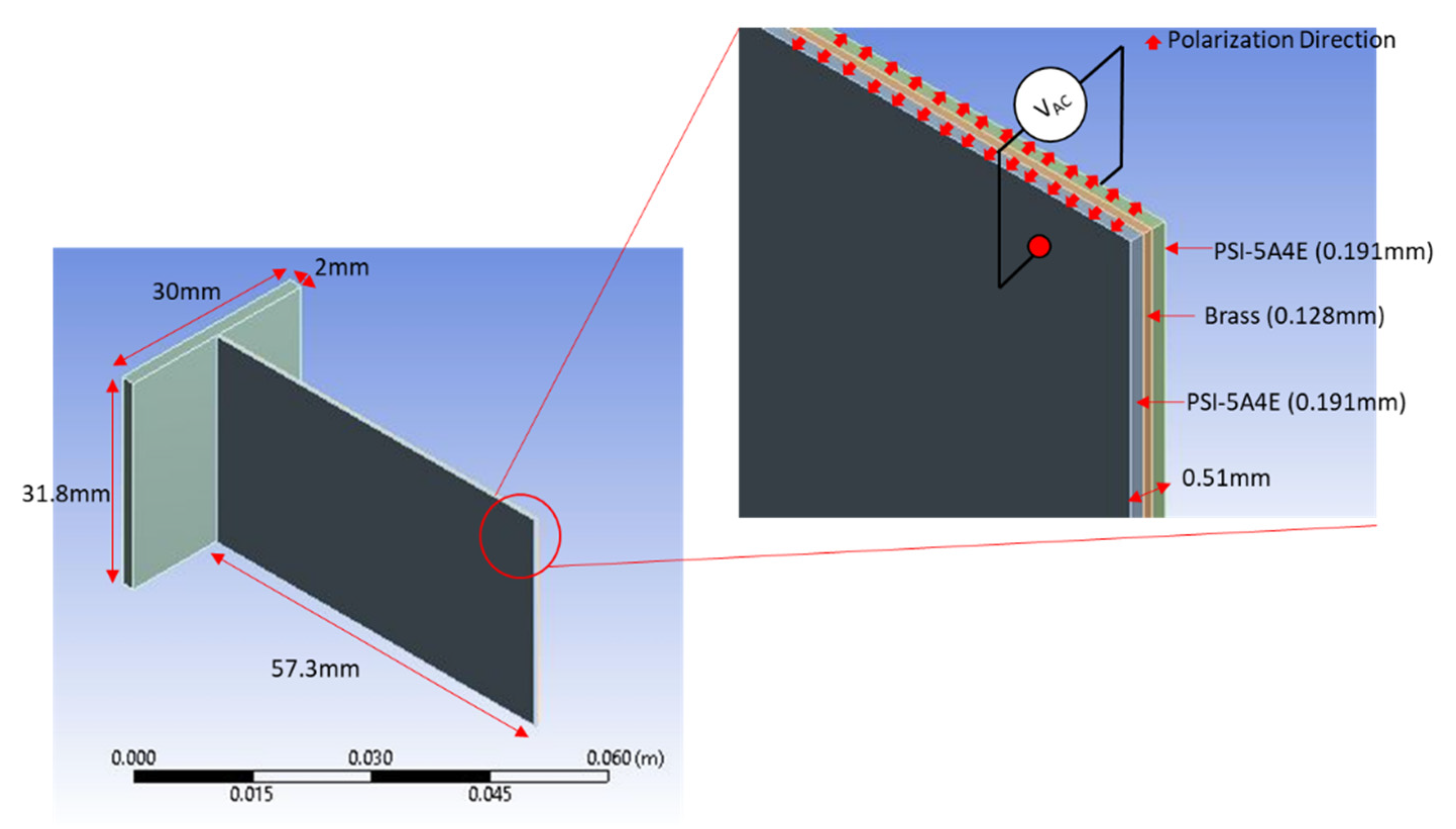
| Material Properties | Steel Bluff Splitter Body | Piezoelectric Plate (PZT) | Piezoelectric Plate (Brass) |
|---|---|---|---|
| Model Dimensions | 31.8 × 30 × 2 mm thick | 31.8 × 57.3 × 0.191 mm thick | 31.8 × 57.3 × 0.128mm thick |
| Density | 7850 kg/m3 | 7800 kg/m3 | 8830 kg/m3 |
| Young′s Modulus | 20 × 1010 Pa | 6.6 × 10¹⁰ Pa (x-dir) 6.6 × 10¹⁰ Pa (y-dir) 5.2 × 10¹⁰ Pa (z-dir) | 1.03 × 10¹¹ Pa |
| Poisson′s Ratio | 0.3 | 0.31 (υxy) 0.242 (υyz) 0.242 (υxz) | 0.34 |
| Piezoelectric Constants | - | e15 = 8.745 Cm−2 e31 = −12.77 Cm−2 e33 = 15.41 Cm−2 | - |
Publisher’s Note: MDPI stays neutral with regard to jurisdictional claims in published maps and institutional affiliations. |
© 2022 by the authors. Licensee MDPI, Basel, Switzerland. This article is an open access article distributed under the terms and conditions of the Creative Commons Attribution (CC BY) license (https://creativecommons.org/licenses/by/4.0/).
Share and Cite
Ong, Z.C.; Kong, K.K.; Khoo, S.Y.; Chew, B.T.; Huang, Y.-H. Enhancement of Vibration Energy Harvesting Performance by Omni-Directional INVELOX Wind Funnel: A Computational Study. Appl. Sci. 2022, 12, 8319. https://doi.org/10.3390/app12168319
Ong ZC, Kong KK, Khoo SY, Chew BT, Huang Y-H. Enhancement of Vibration Energy Harvesting Performance by Omni-Directional INVELOX Wind Funnel: A Computational Study. Applied Sciences. 2022; 12(16):8319. https://doi.org/10.3390/app12168319
Chicago/Turabian StyleOng, Zhi Chao, Keen Kuan Kong, Shin Yee Khoo, Bee Teng Chew, and Yu-Hsi Huang. 2022. "Enhancement of Vibration Energy Harvesting Performance by Omni-Directional INVELOX Wind Funnel: A Computational Study" Applied Sciences 12, no. 16: 8319. https://doi.org/10.3390/app12168319
APA StyleOng, Z. C., Kong, K. K., Khoo, S. Y., Chew, B. T., & Huang, Y.-H. (2022). Enhancement of Vibration Energy Harvesting Performance by Omni-Directional INVELOX Wind Funnel: A Computational Study. Applied Sciences, 12(16), 8319. https://doi.org/10.3390/app12168319