1. Introduction
The half-through tied-arch bridge is a bridge structure that uses flexible cables to connect the ends of the side arches to bear a horizontal thrust. Flexible tie cables often use cables composed of steel strands or parallel steel wires, and their materials and section forms are the same as those of arch-bridge suspenders and cable-stayed bridge cables. In recent years, there have been many instances of damage and fracture accidents of suspenders of arch bridges and cables of cable-stayed bridges [
1,
2], and national specifications stipulate that these cables must be replaced after reaching their service life. In the existing research on cable replacement, the replacement life cycle of arch bridge suspenders is about 15 years [
3], and the replacement cycle of the cables of cable-stayed bridges is about 20 years, but there is less research on the tie cable replacement of the half-through tied-arch bridge.
In the existing research, the cable replacement methods are mainly divided into the non-substitution method and the temporary substitution method. The main difference between them is whether there is a temporary replacement structure to replace the old cable force. The non-substitution method directly removes and replaces the cables that need to be replaced. It is often used in cable-stayed bridges with dense cable systems and high structural redundancy [
4,
5]. According to the redundancy of the structural system, multiple cables can be replaced at the same time. Because the non-substitution method directly removes the cable force, it will cause large changes in internal force, which can be implemented only when the structure itself has sufficient bearing capacity. The temporary substitution method replaces the original cable force by installing temporary structures. The commonly used temporary substitution method is divided into the temporary suspender method, the arch-rib pocket-lifting method, the bridge-deck pocket-lifting method, etc. Due to the existence of the replacement device, it has little impact on the old structure. The temporary substitution method is widely used in cable replacement of cable-stayed bridges with thin cable systems [
6], suspension-bridge suspender replacement [
7,
8], and arch-bridge suspender replacement [
9,
10,
11].
The temporary substitution method needs to solve the problem of the replacement numbers and replacement steps. The choice of replacement number and replacement steps is mainly related to the bearing capacity of the bridge structure. The main beam, bridge tower, and adjacent cables are involved in cable-stayed bridges, the bridge deck and adjacent suspenders are involved in suspension bridges, and the arch rib, bridge deck system, and adjacent suspenders are involved in arch bridges. When the bearing-capacity margin of the original structure is small, the single-cable-replacement method may be adopted. When the bearing capacity margin of the original structure is large enough, more cables can be replaced at the same time or in fewer replacement steps. By reasonably adjusting the cable-force-transformation process, the temporary replacement method can achieve equivalent replacement [
9,
10], which is theoretically applicable to all cable-replacement scenarios. However, due to the need to install temporary replacement devices on the original structure, there is a risk of damage to the structure and high-altitude operation. Most existing research on the replacement of tie cables of arch bridges adopts the temporary substitution method, which gradually replaces the cable force of the old tie cables by adding temporary tie cables [
12,
13]. The change in the cable force in the replacement process produces internal force distribution in the arch bridge, so it is necessary to ensure the safety of the original structure, such as the arch rib, adjacent tie cable, and foundation during the replacement of the tie cable [
14].
The function of the flexible tie cable in the half-through tied-arch bridge is different from that of the cable-stayed bridge, arch bridge, and ordinary tied-arch bridge. It is mainly used to balance the horizontal thrust at the bridge foundation. When the cable force of the tie cable is lost, the tension will be passed to the bridge foundation [
15], so the horizontal force-bearing capacity of the foundation affects the selection of the tied-cable-replacement method. There are few studies on the impact of tie-cable replacement on the substructure of the half-through tied-arch bridge.
To find the most suitable method of the tie-cable replacement of the half-through tied-arch bridge, this study takes a half-through concrete-filled steel tube (CFST) tied-arch bridge with a main span of 110 m as an example in order to study the applicability of various replacement schemes based on the non-substitution method and the temporary substitution method. Based on the response of the structure under different replacement schemes, feasibility analysis and scheme comparison was carried out, and the replacement structure design and construction method were introduced. It is hoped that this study can provide a reference for the replacement of the tie cable of the half-through tied-arch bridge.
2. Bridge Constitution
The third Lingjiang bridge is located on the Lingjiang River in Linhai City, China. The bridge was completed and opened to traffic in 2009, and its structural form is a three-span half-through tied-arch bridge with a span arrangement of 36 m + 110 m + 36 m. The main arch-rib section adopts a truss concrete-filled steel tubular structure, with a rising height of 27.5 m and a rising span ratio of 1/4. The side arch rib adopts a reinforced concrete structure, with a rise height of 10 m and a rise span ratio of 1/7.2. The make-up steel strand tie cable is anchored at the ends of the side arches. The model of the tie cable is OVMXG15-19-B high-strength low relaxation steel strand, with a strength of 1860 MPa. Six tie cables are arranged on one side, with a total of 12 tie cables on the whole bridge. The substructure of this bridge adopts a pile-cap foundation, and the arch toes of the main arch and side arch are consolidated in the arch seat. According to the principle that the direction from the small station to the large station is positive, the left side is upstream and the right side is downstream. The layout of this type of bridge is shown in
Figure 1.
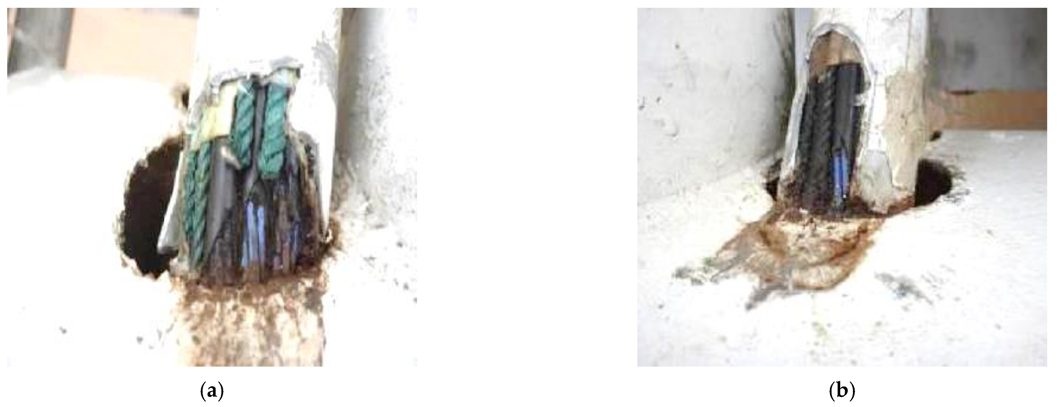
After ten years of operation, and due to the continuous friction between the tie cable and the main arch rib, three tie cables were damaged at the position where they passed through the main arch rib, among which the damage to tie cables #11 and #12 was the most serious. Through on-site inspection, it was found that three steel strands in tie cable #11 were broken, and eight steel strands were worn, as shown in
Figure 2a. The PE protective sleeve of the tie cable #12 was damaged, as shown in
Figure 2b.
The damage to the tie cables seriously affects the safety of the bridge. To prevent its subsequent development into tie cable fracture, which could cause more serious structural damage, this study focuses on the replacement methods of the tie cable of such bridges, hoping to provide technical guidance for the subsequent tie cable replacement.
3. Replacement Scheme and Finite Element Simulation Method
3.1. Replacement Scheme
To study the applicability of different replacement methods in a half-through tied-arch bridge, four non-substitution method schemes and four temporary substitution method schemes were designed, as shown in
Table 1.
The principle of the non-substitution method is simple and can be divided into two steps: the first step is to cut off the old tie cable, and the second step is to tension the new tie cable. The principle of the temporary substitution method is to first convert the cable force of the old tie cable to the temporary structure and then convert the tie cable force to the new tie cable by the temporary structure.
Considering the influence of the tensioning step on the bridge structure and the construction efficiency, the equal step-tensioning method was adopted in this study. According to the step of 1/4 cable force of the tie cable, the old tie cable is unloaded and the new tie cable is tensioned.
3.2. Finite Element Simulation Method
The tie cable replacement analysis model of the third Lingjiang bridge was established by using the Midas/Civil 2021 finite element analysis software, as shown in
Figure 3. The main arch rib, side arch rib, cross beam, pier, and pile were simulated by the beam element, and the suspender and tie cable were simulated by the truss element.
The concrete of the arch ribs on the side arch was C50, and the elastic modulus was 34,500 MPa. Q345 steel is used for the steel pipe of the main arch rib, with an elastic modulus of 210,000 MPa. The steel pipe is filled with micro-expansion C50 concrete. The tie cable is made of a steel strand with a design strength of 1860 MPa and an elastic modulus of 195,000 MPa. The suspender adopts a parallel steel wire with a design strength of 1760 MPa and an elastic modulus of 195,000 MPa. The hanger beam and column beam were made of Q345 steel. C30 concrete was adopted for the arch seat, and C25 concrete was adopted for the pile foundation.
The boundary condition was that the main arch and side arch were fixed at the top of the arch seat. The suspender was hinged to the arch rib and cross beam, and the tie cable was hinged to the side arch rib. The bridge deck and the beam were connected by common nodes. The boundary condition of the pile included the pile-bottom constraint and pile-side soil friction. The vertical fixed constraint was imposed on the pile bottom, and the constraint of the pile-side soil was simulated by soil spring. First, starting from the local scouring line, the pile was divided into a section of 2 m, and then according to the pile length, calculated width, and foundation horizontal resistance coefficient, the soil stiffness at the corresponding node was calculated, and finally, the stiffness value was given to the plane direction of the pile nodes.
The removal and installation of the tie cable in the non-substitution method scheme were realized by using the unit “passivation” function, and the tensioning and unloading of the temporary tie cable in the temporary substitution method scheme was realized by using the “initial tension replacement” function. Since the replacement of tie bars needs to interrupt the traffic, only the dead load was considered in the replacement process.
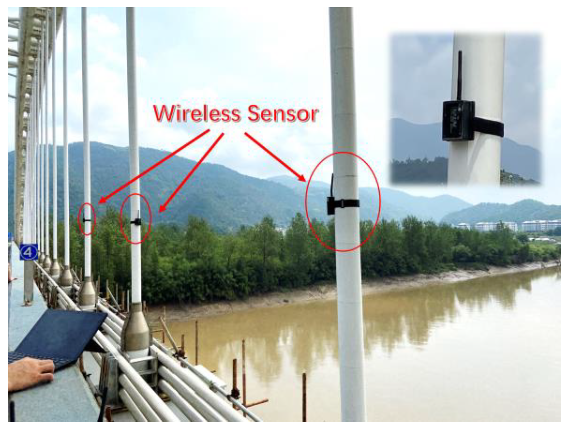
To verify the accuracy of the finite-element model, the suspender cable force was selected as the verification index. The calculated suspender force of the model was compared with the field-measured suspender cable force. The DH5906W cable-force sensor was used to measure the cable force of the suspender based on the frequency method, as shown in
Figure 4.
The comparison of the designed cable force, calculated cable force, and measured cable force are shown in
Table 2.
It can be seen from
Table 2 that the maximum deviation between the calculated cable force and the design cable force was 3.1% (R6, R15), and the total cable force deviation was 0.4%. The maximum deviation between the calculated cable force and the measured cable force was less than 15%, and the total cable-force deviation was 1%, which shows that the calculated model was in good agreement with the field test and verifies the effectiveness of the finite element model.
4. Results
4.1. Results of the Impact of Each Replacement Scheme on the Substructure
The arch rib and arch seat of the half-through tied-arch bridge were consolidated, and the horizontal forces of the main arch, side arch, and tie cable were balanced at the arch seat, so the arch seat and pile foundation were sensitive to the cable force changes in the tie cable. Therefore, the impact of each replacement scheme on the safety of the substructure needs to be considered first.
The type of bridge pile is the friction pile. The pile adopts a circular section with a diameter of 1.5 m. The longitudinal reinforcement is arranged as 32 HRB335 reinforcements with a diameter of 28. The pile length is 44 m, and the depth below the local scouring line is 30 m. The pile foundation layout and soil layer distribution are shown in
Figure 5.
To ensure the safety of the pile during the replacement of tie cables, the construction process was controlled according to the principle that there is no tensile stress during the replacement process. According to the model, the axial force of each pile under the dead load is 6438.3 kN, and the bending moment of the pile when tensile stress is about to appear is 1207.5 kN, which is the control bending-moment value during replacement.
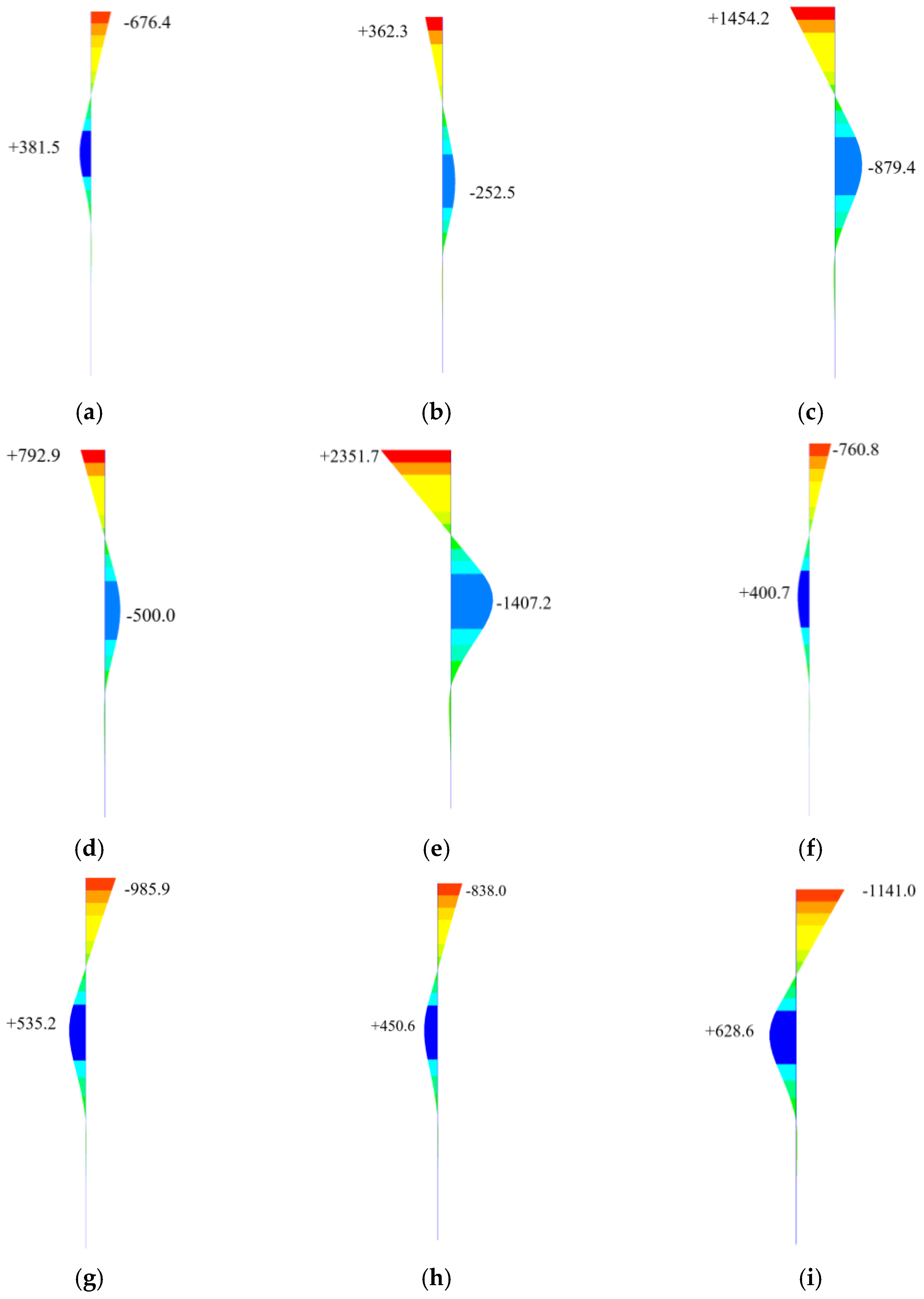
The most unfavorable state of pile stress is the state after cutting off the old tie cable in the non-substitution method schemes and the state after tensioning the temporary tie cable in the temporary substitution method schemes. The bending moment of the pile under each scheme is shown in
Figure 6:
It can be seen from
Figure 6a that the bending moment at the pile top is negative under the dead load, indicating that the total horizontal thrust of the arch seat is toward the middle of the main span. In
Figure 6b of scheme 1, due to tie cable 1# being removed, the direction of the horizontal force changes. With the increase in the number of tie cables removed, the bending moment at the pile top gradually increases, as shown in
Figure 6c–e. In the temporary substitution schemes, the direction of the pile-top bending moment is the same as that under the dead load, and the pile-top bending moment increases with the increase in the number of tie cable replacements, as shown in
Figure 6f–i. It can also be seen from
Figure 6 that
- (1)
The bending moments of the pile caused by schemes 2, 4, and 8 are 1454.2 kN, 2351.7 kN, and −1141.0 kN, respectively, of which the bending moment value of scheme 2 and scheme 4 exceeds the limit value.
- (2)
In the non-substitution-method schemes, only one-sided single-tied cable replacement (scheme 1) and two-sided single-tie cable replacement (scheme 3) meet the need for the principle of no tensile stress in the piles.
- (3)
In the temporary-substitution-method schemes, the bending moment of the pile changes slightly, and the bending moment value caused by scheme 8 is the largest.
4.2. Results of the Impact of Each Replacement Scheme on the Superstructure
After scheme 2 and scheme 4 were eliminated due to the fact that they exceeded the limit stress of the pile, the impact of the remaining six replacement schemes on the superstructure of the bridge was further studied. In the superstructure, the stress states of the arch rib and adjacent tie cables were selected for comparison.
As the main load-bearing member of the arch bridge, the arch rib bears the role of transferring the upper load to the lower structure. We selected the arch rib sections at the main arch crown (S1), L/4 of the main arch (S2), main arch foot (S3), side arch foot (S4), L/2 of the side arch (S5), and side arch crown (S6) for analysis.
4.2.1. Axial Force of Arch Rib
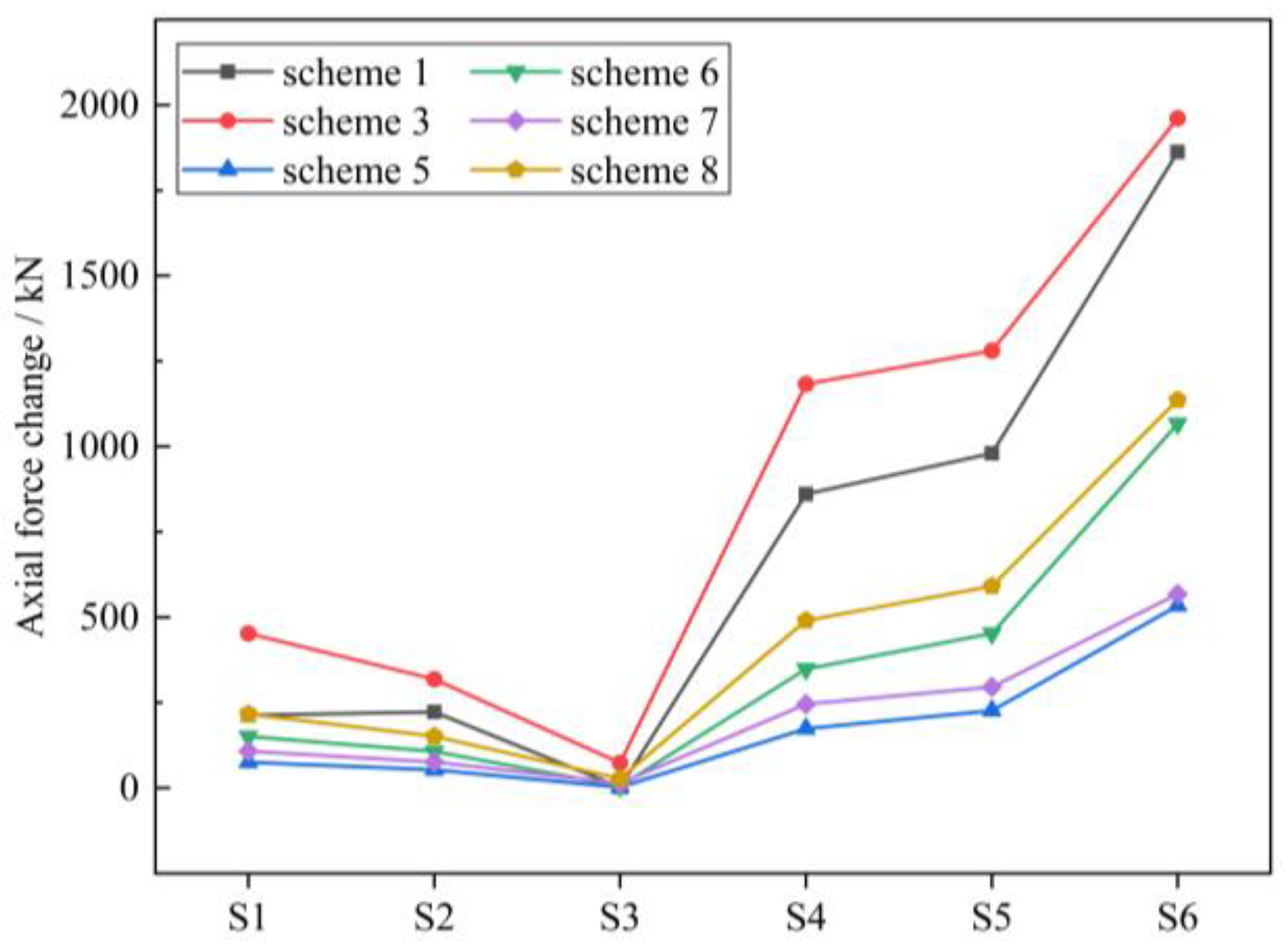
The influence of each tie cable replacement scheme on the axial force of the arch rib is shown in
Figure 7.
It can be seen from
Figure 7 that the axial force of the side arch rib sections changes greatly, and the section of the side arch crown S6 changes the most. It can also be seen that
- (1)
The change in the axial force of the arch rib caused by scheme 1 and scheme 3, which use the non-substitution method, is similar, and both are greater than that of the temporary substitution method schemes.
- (2)
Comparing scheme 5 and scheme 7, it is found that their axial force changes are similar in each section. The change in axial force caused by scheme 6 and scheme 8 in each section is similar, and their value is about twice that of scheme 5 and scheme 7.
- (3)
In each scheme, the axial force of the side arch crown S6 section is the most sensitive, and the axial force of the S3 section at the arch foot of the main arch is the least sensitive to the replacement of tie cables.
4.2.2. Bending Moment of Arch Rib
The influence of the tie-cable replacement on arch rib bending moment is shown in
Figure 8.
It can be seen from
Figure 8 that the bending moment of the main arch foot section S3 changes the most. It can also be seen that
- (1)
The bending moment of arch rib caused by the non-substitution method scheme 1 and scheme 3 changes greatly, while the temporary substitution method scheme has little effect on the bending moment of arch rib.
- (2)
During the replacement of the tie cables, each scheme has little influence on the bending moment of the main arch-crown section S1 and L/4 of the main span section S2. The influence of each scheme on the bending moment of the side arch rib is relatively small, and the changes are within 1000 kN·m.
- (3)
The bending moment changes caused by scheme 5 and scheme 7 are nearly the same. The bending moment changes caused by scheme 6 and scheme 8 are nearly the same, and this value is about twice that of scheme 5 and scheme 7.
- (4)
At the arch foot section S3, scheme 1 and scheme 3 with the non-substitution method cause the largest bending moment, followed by scheme 8 and scheme 6 with the replacement of two tie cables on the same side. Scheme 5 and scheme 7, with the replacement of one suspender on the same side, result in the minimum change in the arch rib bending moment.
4.2.3. Arch Rib Deformation
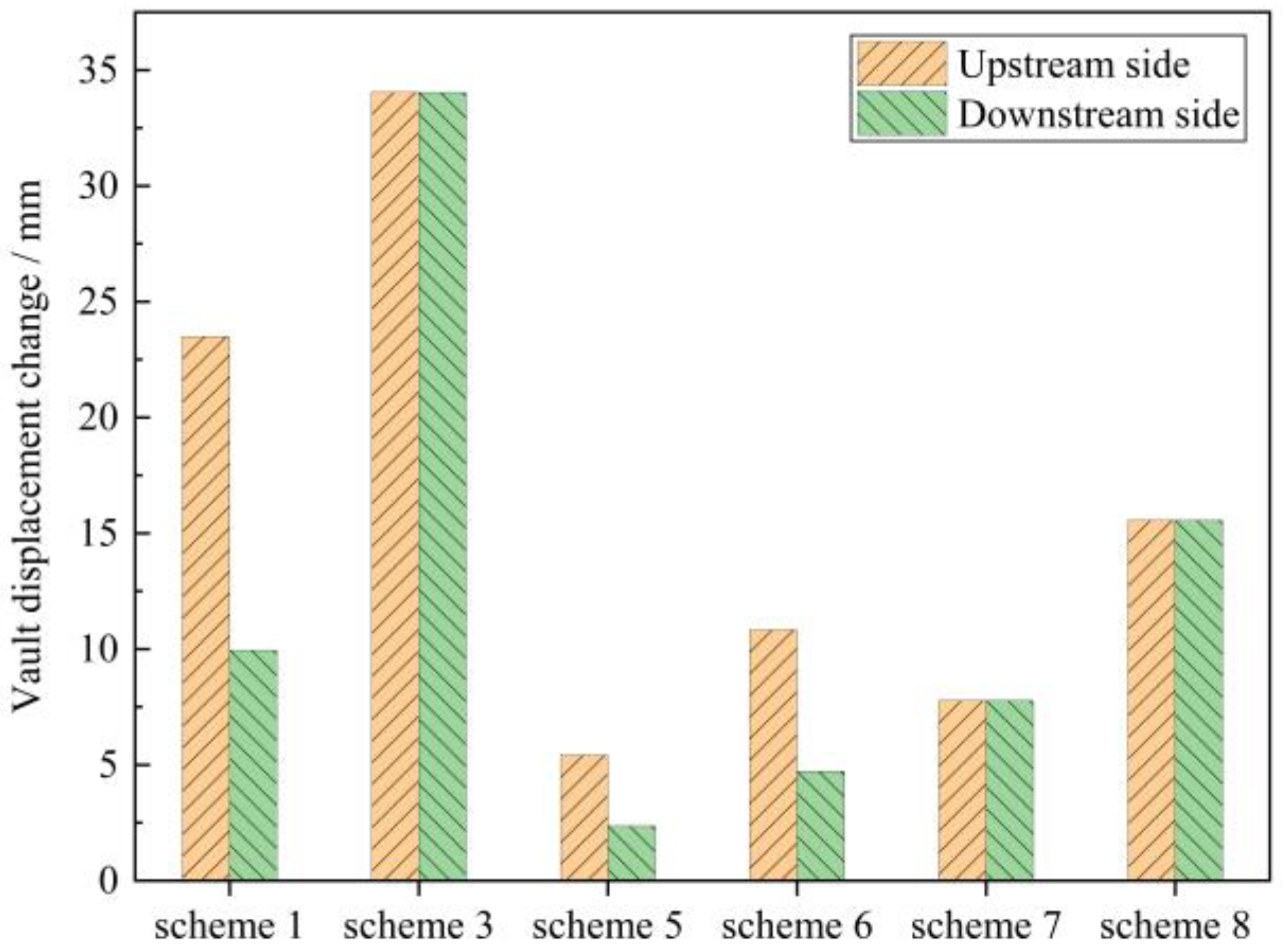
The influence of tie cable replacement on the displacement of the main arch crown is shown in
Figure 9.
Since the upstream side was selected for the unilateral replacement scheme, the displacement of the upstream side of schemes 1, 5, and 6 is greater than that of the downstream side. It can be seen from
Figure 9 that
- (1)
The displacement caused by scheme 1 and scheme 3 using the non-substitution method is larger, and the maximum displacement is 34.5 mm in scheme 3. The arch rib deformation caused by the temporary substitution method is smaller, and the maximum is 15.2 mm in scheme 8.
- (2)
The displacement of the main arch caused by scheme 5 is the smallest, followed by scheme 7. This indicates that the temporary substitution method of replacing one by one (scheme 5) and one by one symmetrically on both the upstream and downstream sides (scheme 7) has the least influence on the displacement of the main arch crown.
- (3)
In the temporary substitution schemes, the deformation of one side arch rib is linearly related to the number of cables replaced on this side. For example, the deformation of the arch rib caused by scheme 8 is about twice that of scheme 7.
4.2.4. Cable Force of Adjacent Tie Cables
The impact of the tie cable replacement on adjacent tie cables is shown in
Figure 10.
Figure 10 shows the maximum cable force variation of each tie cable in different replacement schemes. It can be seen that
- (1)
The influence of the non-substitution method’s scheme 1 and scheme 3 on the cable force of adjacent tie cables is greater than that of temporary substitution method schemes, and the maximum value appears at 150 kN of scheme 3.
- (2)
The change in the cable force of adjacent tie cables caused by scheme 5 is the smallest, followed by scheme 7.
- (3)
When the tied cable on one side was replaced, the cable force of the tie cables on the other side will also be affected. For example, replacing #1 and #2 in scheme 6 will not only increase the cable force of 3#~6# but also increase the cable force of tie cables #7~#12 by 20 kN.
4.3. Scheme Comparison
- (1)
After considering the safety of the pile and excluding scheme 2 and scheme 4, the impact of each scheme on the superstructure was compared, and it was found that the non-substitution method scheme is relatively unfavorable and the temporary substitution method scheme has little impact on the stress of the original structure, which is more favorable, so scheme 1 and scheme 3 are excluded.
- (2)
From the perspective of the stress and deformation of the arch rib, the internal force and deformation of the arch rib caused by scheme 6 and scheme 8 are twice that of scheme 5 and scheme 7. From the perspective of the safety of the arch rib, scheme 5 and scheme 7 are more beneficial to maintaining structural safety in the tie-cable-replacement process.
- (3)
From the perspective of force changes in adjacent tie cables, the cable force changes in the adjacent tie cables caused by scheme 5 and scheme 7 are smaller than those caused by scheme 6 and scheme 8, so scheme 5 and scheme 7 are more beneficial to maintaining the old tie cables safety.
To sum up, from the perspective of the structural stress state, scheme 5 and scheme 7 can not only ensure structural safety but also achieve little impact on the original structure, which is more suitable for the replacement of tie cables of the half-through tied-arch bridge. From the perspective of construction, although scheme 7 causes slightly larger displacement and adjacent tie-cable force changes than scheme 5, the replacement construction efficiency of scheme 7 is higher than that of scheme 5, so scheme 7 is finally determined to be the best scheme.
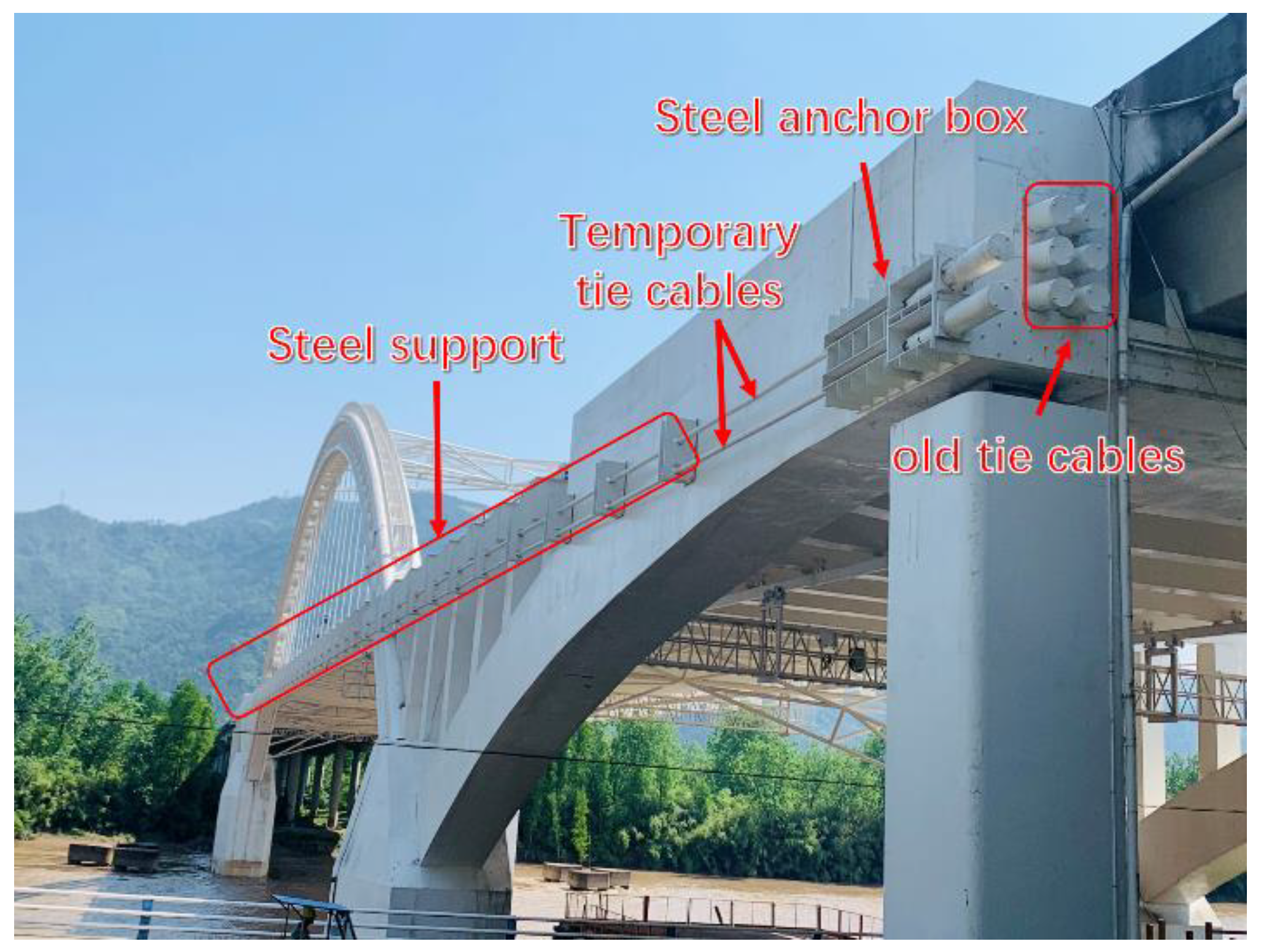
5. Design and Implementation of the Temporary Replacement System
Given there is little existing research on the temporary replacement device for the tie cables of half-through tied-arch bridges, this paper puts forward a design scheme for the temporary substitution system. The temporary substitution system consists of three parts, as shown in
Figure 11: the steel anchor box, the support frame, and the temporary tie cable.
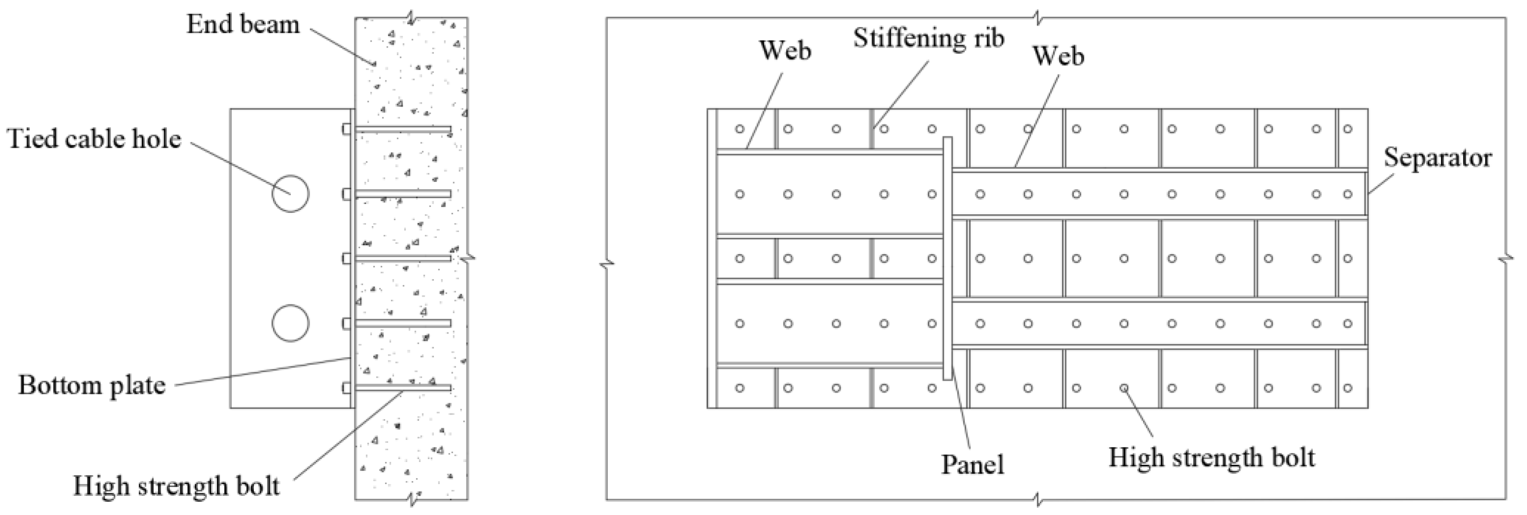
The steel anchor box is welded with a Q345C steel plate with a thickness of 2.0 cm. The interior is separated and fixed by steel plates and is equipped with tie bar channels, which can anchor two temporary tie cables at the same time. The steel anchor box is anchored in the end transverse beam through M16 anchor bolts. The structure of the steel anchor box is shown in
Figure 12.
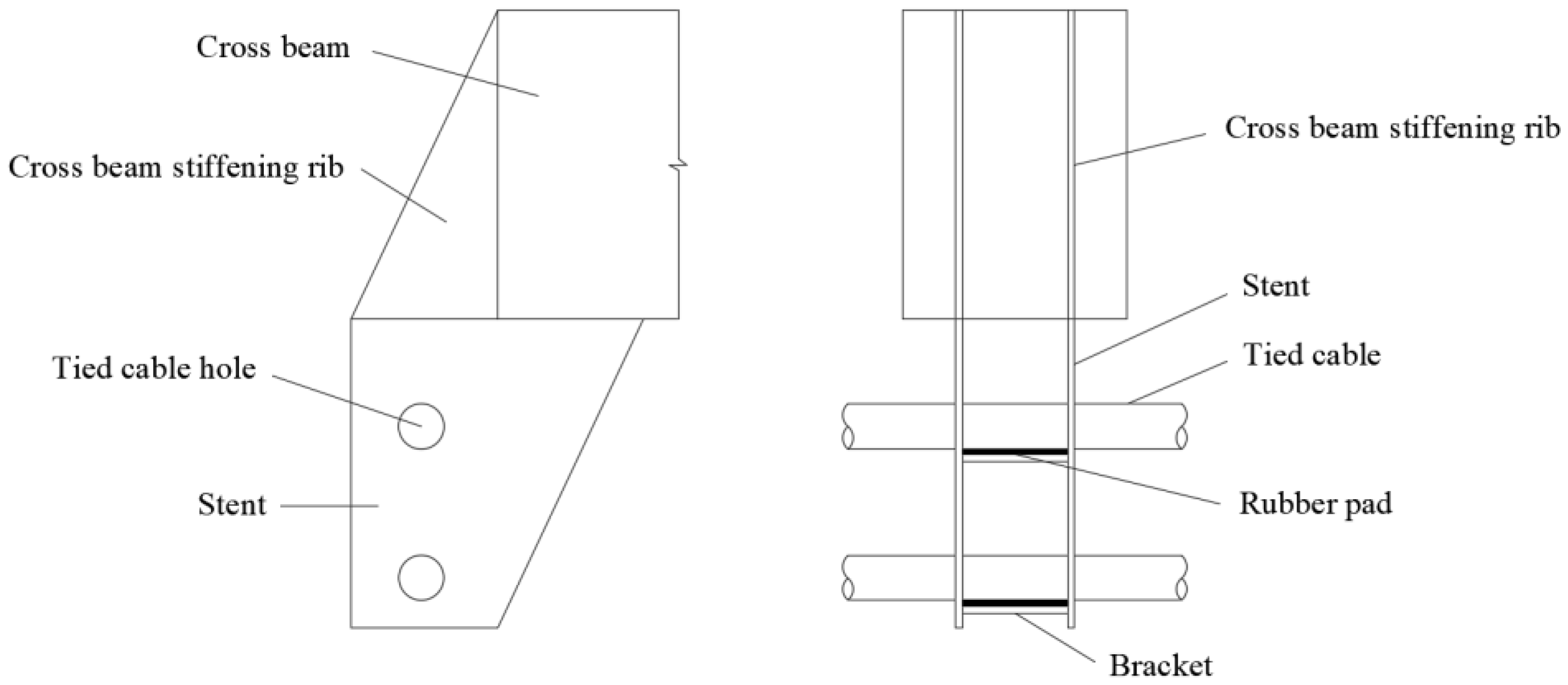
The support frame is also welded with a Q345C steel plate, which is used to support the temporary tie cable to prevent excessive sag. To prevent the tie cable and the support frame from being damaged due to friction, rubber pads are placed on the support frame. The supporting structure is shown in
Figure 13.
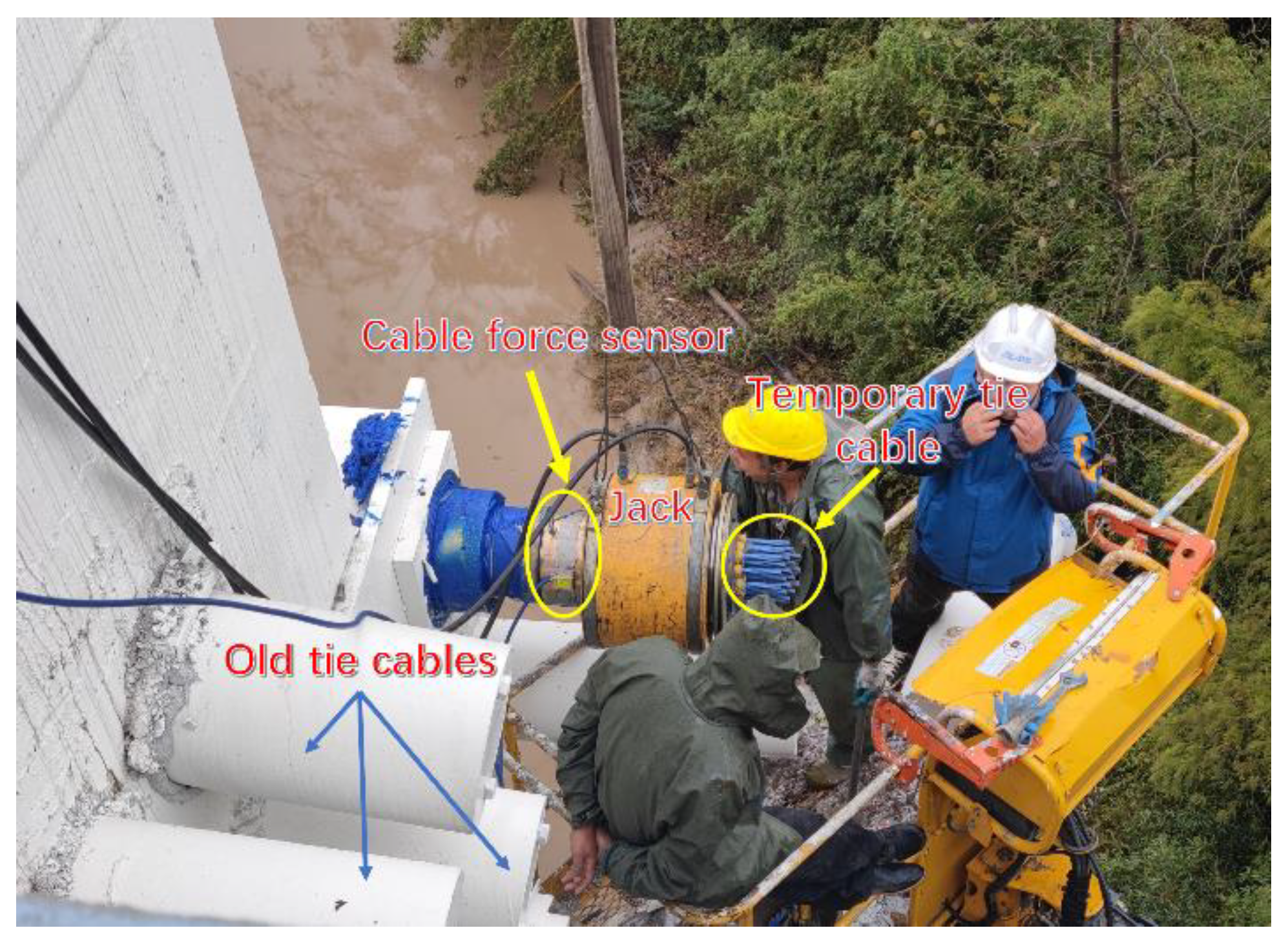
The temporary tie cable adopts epoxy coating 19 ×
φs 15.2 steel strand, with the strength of 1860 MPa. The steel strand is wrapped with an HDPE protective layer, which can effectively prevent corrosion. After the steel anchor box, support frame, and temporary tie cables were installed, the temporary tie cables were tensioned by the jack. The tensioning method consisted of symmetrical tensioning of the upstream and downstream tie cables, as shown in
Figure 14.
Due to the damage to the tie cable of the third Lingjiang bridge, the temporary tie cables were first installed and tensioned for safety reserve, and then the tie cables will be replaced according to the best scheme.
6. Conclusions
Half-through flexible tied-arch bridges face the problem of tie-cable replacement, but there are few studies in this area. In this study, eight replacement schemes were designed based on whether there was an alternative structure. According to finite-element analysis, the influence of each replacement scheme on the main components of the half-through tied-arch bridge was compared, and the best scheme was selected. Based on the best scheme, the temporary replacement structure was designed and implemented.
It was found that in the half-through tied-arch bridge, the pile was greatly affected by the change in the tie cable force, and the stress state of the pile should be paid more attention to in the tie-cable replacement of this kind of bridge. When more tie cables were replaced by the non-substitution method, this will cause a very large bending moment change and may lead to cracking of the pile. Compared with the temporary substitution method, the non-substitution method will not only cause a large bending moment in the pile but also cause a large internal force change between the arch rib and the adjacent tie cables. Due to the existence of temporary replacement components, temporary substitution schemes have little impact on the original structure in the replacement process, which is more suitable for the replacement of the tie cable of the half-through tied-arch bridge. The temporary replacement method of replacing tie cables using schemes of one-by-one at both sides can not only reduce the impact on the original structure but also have a fast replacement speed, which can be applied in the tie cable replacement of the same type of bridge.
Since this study is based on a specific bridge, the optimization of the multi-objective replacement scheme considering structural capacity, construction convenience, and economy needs to be further studied in the tie cable replacement of half-through tied-arch bridge.
Author Contributions
Conceptualization, Y.X. and G.S.; methodology, B.Z.; resources, Z.Z.; data curation, G.S.; writing—original draft preparation, G.S.; project administration, H.J. All authors have read and agreed to the published version of the manuscript.
Funding
This research was funded by the Taizhou Science and Technology Plan Project (22gyb004).
Institutional Review Board Statement
Not applicable.
Informed Consent Statement
Not applicable.
Data Availability Statement
Not applicable.
Acknowledgments
We are grateful for the comments of the anonymous reviewers, which greatly improved the quality of this paper.
Conflicts of Interest
The authors declare no conflict of interest.
References
- Fan, Z.Y.; Ye, Q.W.; Xu, X.; Ren, Y.; Huang, Q.; Li, W.Z. Fatigue reliability-based replacement strategy for bridge stay cables: A case study in China. Structures 2022, 39, 1176–1188. [Google Scholar] [CrossRef]
- Iordachescu, M.; Valiente, A.; De Abreu, M. Effect of environmentally assisted damage on fatigue resistance of tie-down cables after 30 years of service in a cable-stayed bridge. Eng. Fail. Anal. 2021, 126, 105455. [Google Scholar] [CrossRef]
- Shao, G.; Jin, H.; Jiang, R.; Xu, Y. Dynamic Response and Robustness Evaluation of Cable-Supported Arch Bridges Subjected to Cable Breaking. Shock Vib. 2021, 2021, 6689630. [Google Scholar] [CrossRef]
- Fu, Z.Q.; Ji, B.H.; Yang, M.Y.; Sun, H.B.; Maeno, H. Cable Replacement Method for Cable-Stayed Bridges Based on Sensitivity Analysis. J. Perform. Constr. Facil. 2015, 29, 04014085. [Google Scholar] [CrossRef]
- Li, H.J. Replacement of Cable Stays in Yonghe Bridge in Tianjin, China. Adv. Civ. Eng. 2020, 2020, 17. [Google Scholar] [CrossRef]
- Mehrabi, A.B. Luling Bridge Stay Cable Replacement. In Proceedings of the Structures Congress 2009, Austin, TX, USA, 30 April –2 May 2009; pp. 1–10. [Google Scholar]
- Yuan, A.M.; Yang, T.; Xia, Y.F.; Qian, L.F.; Dong, L.F.; Jin, X.H. Replacement of the Fire-Damaged Long Suspenders of the Runyang Suspension Bridge. Struct. Eng. Int. 2021, 1–7. [Google Scholar] [CrossRef]
- Feng, D.M.; Mauch, C.; Summerville, S.; Fernandez, O. Suspender Replacement for a Signature Bridge. J. Bridge Eng. 2018, 23, 05018010. [Google Scholar] [CrossRef]
- Granata, M.F. Stressing Sequence for Hanger Replacement of Tied-Arch Bridges with Rigid Bars. J. Bridge Eng. 2022, 27, 04021099. [Google Scholar] [CrossRef]
- Wang, H.; Wang, L.L.; Zhuo, X.L.; Huang, K.N.; Wang, X.R.; Wang, W.S. Study on the Precise Displacement Controlling Method for a Suspended Deck in the Hanger Replacement Process of an Arch Bridge. Appl. Sci. 2021, 11, 9607. [Google Scholar] [CrossRef]
- Deng, Y.L.; Deng, L.M. Suspender Replacement Method for Long-Span Concrete-Filled Steel Tubular Arch Bridges and Cable Force Measurement Based on Frequency Method. Adv. Civ. Eng. 2021, 2021, 21. [Google Scholar] [CrossRef]
- Zhang, Z.Q.; Jiang, S.; Kang, X.X.; Yao, Y.; Hu, J. Tied-bar Replacement Construction Technology of Large-span Flying-swallow-typed Tied-arch Bridge. Constrction Technol. 2018, 47, 96–100. [Google Scholar]
- Kang, X.X.; Liu, L.; Ding, H.H. Research and construction on key technology of tie bar replacement of Tied Arch Bridge. Highway 2015, 60, 110–114. [Google Scholar]
- Cui, X.P. Study on the Prestress Loss and Replacement Technology of Flexible Tied Bar of Flexible Tied Arch Bridge. Master’s Thesis, Chongqing Jiaotong University, Chongqing, China, 2015. [Google Scholar]
- Tang, C.Y.; Zheng, L.; Zhang, Z. Construction Controls for a Half-Through Tied Arch Bridge in China. Struct. Eng. Int. 2014, 24, 557–561. [Google Scholar] [CrossRef]
| Publisher’s Note: MDPI stays neutral with regard to jurisdictional claims in published maps and institutional affiliations. |
© 2022 by the authors. Licensee MDPI, Basel, Switzerland. This article is an open access article distributed under the terms and conditions of the Creative Commons Attribution (CC BY) license (https://creativecommons.org/licenses/by/4.0/).


