
Compatibility Improvement of Interrelated Items in Exchange Files—A General Method for Supporting the Data Integrity of Digital Twins


Abstract
:1. Introduction
2. Materials
2.1. Fundamentals of Data Exchange and Extraction
2.2. Fundamentals of File Formats
- Hierarchy—A tree structure arranges the stored data. A root element represents the top level and contains the entirety of the information saved in the document. Child elements divide the root element, which can be subdivided into deeper nestings. The lowest level in each case represents the direct data.
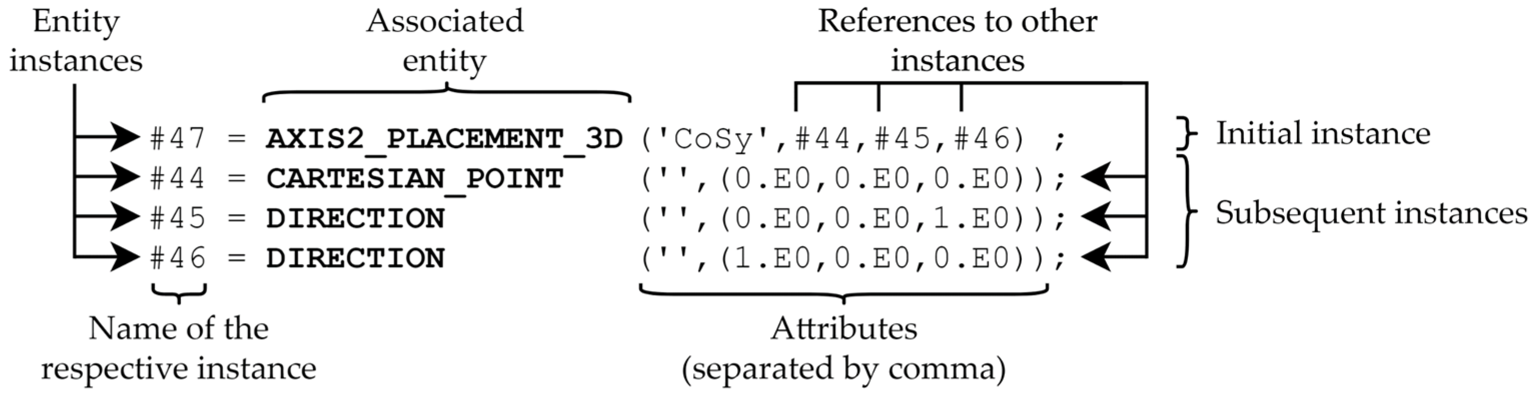
- Relation—Each stored piece of information has a unique identification key that links the data using references. The keys can be either numbers or strings.
- Block—Blocks in the file store the data. Each block represents a coherent piece of information, and unions have no or only a weak connection to one another.
2.3. Fundamentals of the STEP File Format
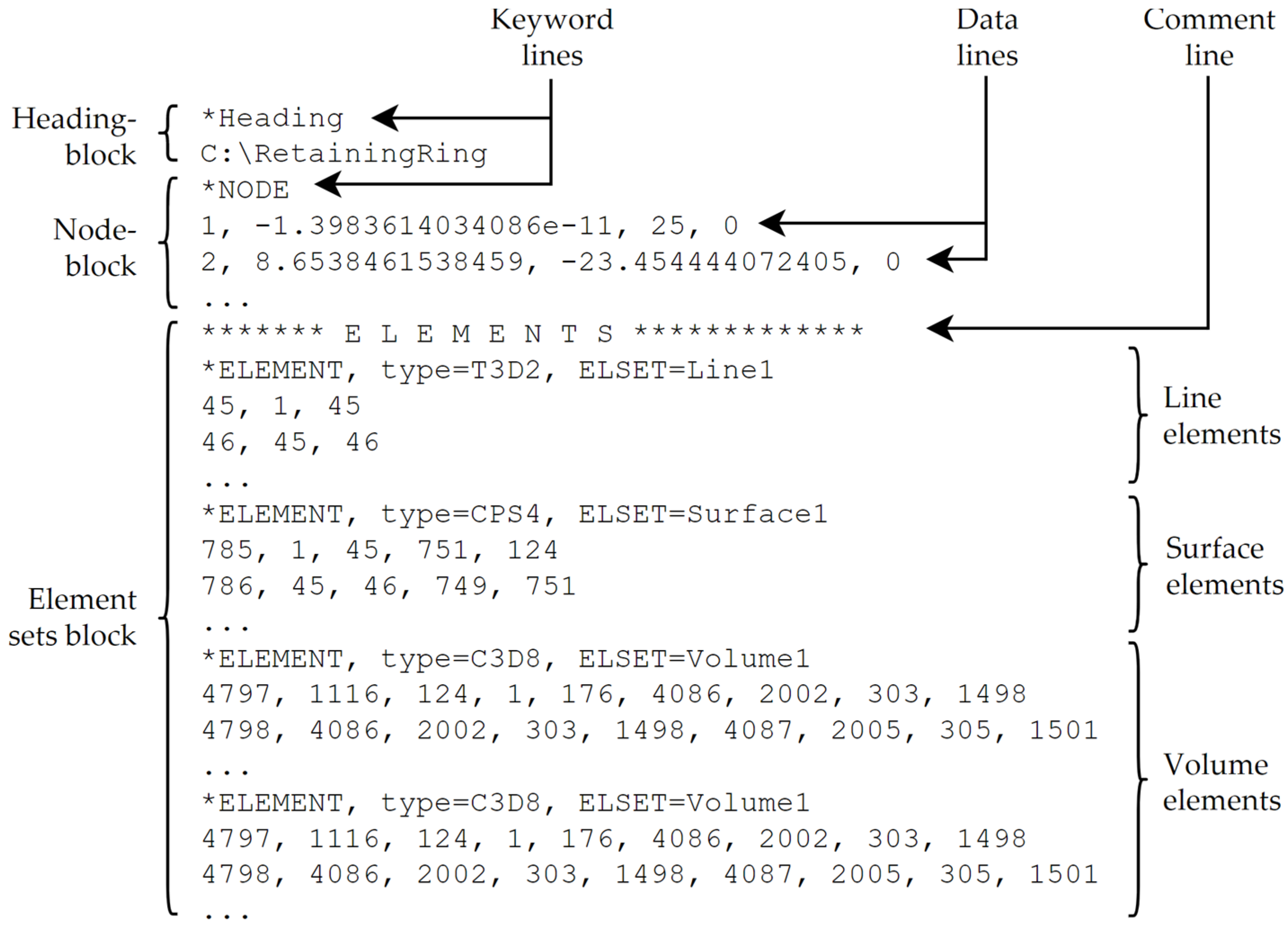
2.4. Fundamentals of the INP File Format
3. Proposed Method
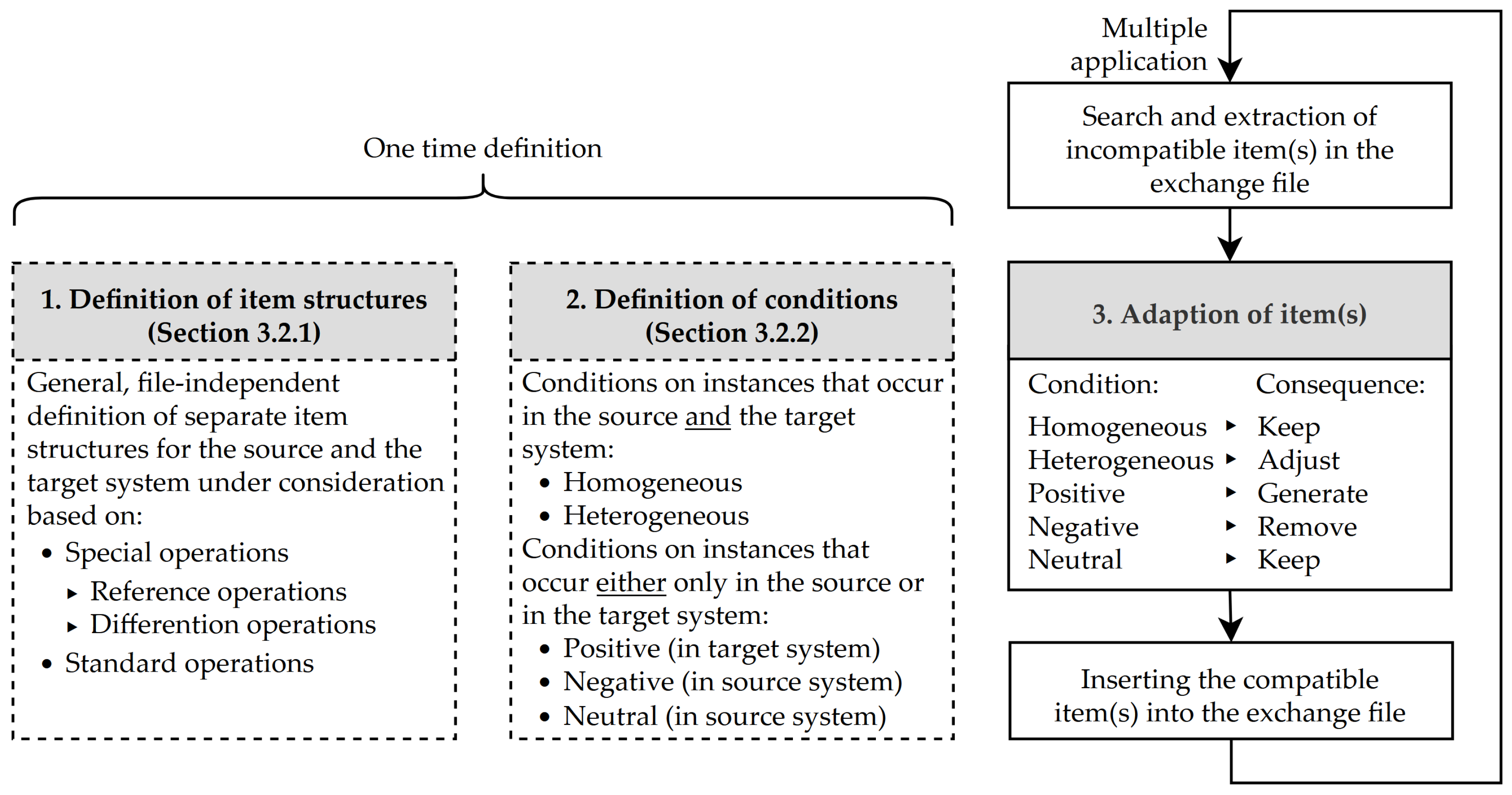
3.1. General Description of the Steps of the Compatibility Improvement Approach
3.2. Description of the Individual Steps of the Compatibility Improvement Approach
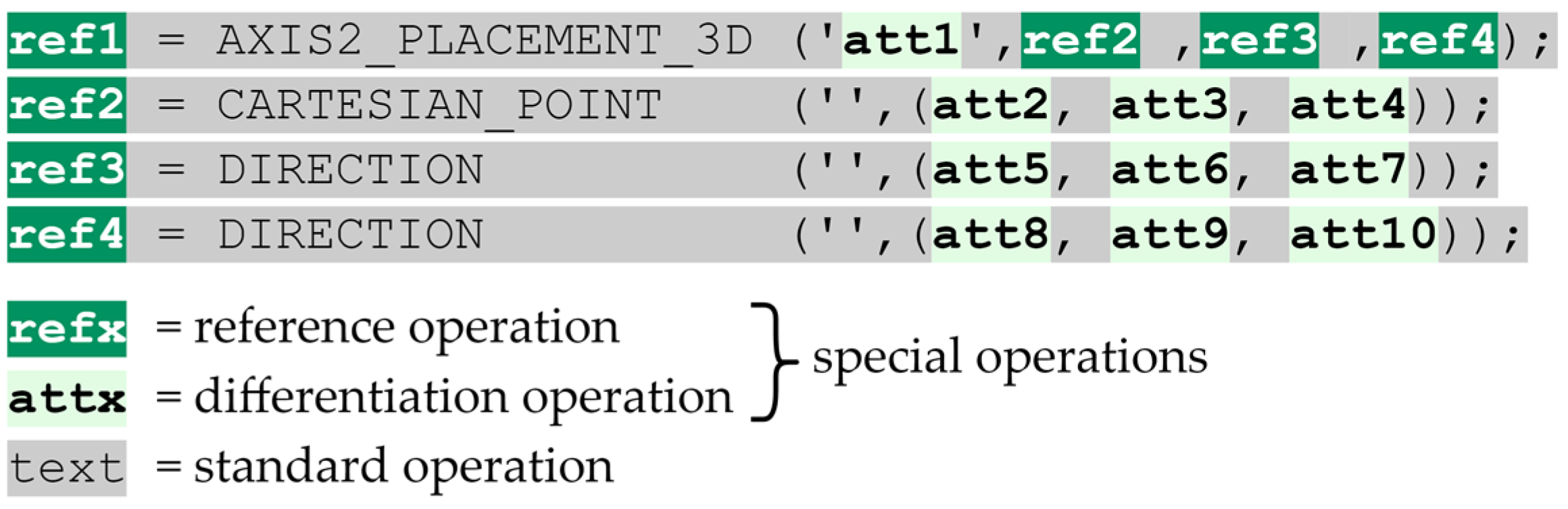
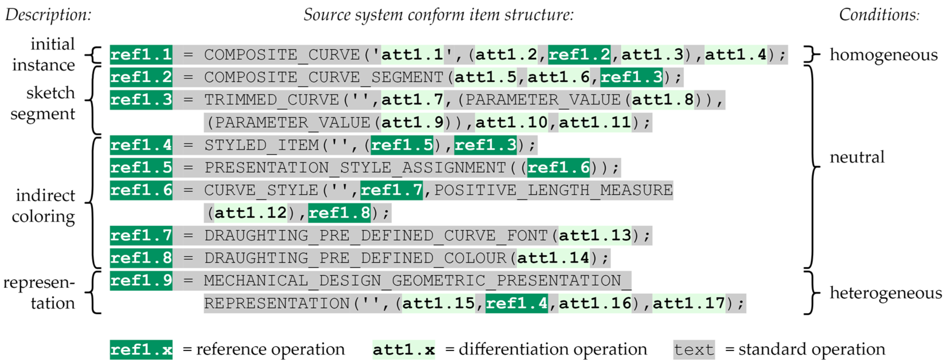
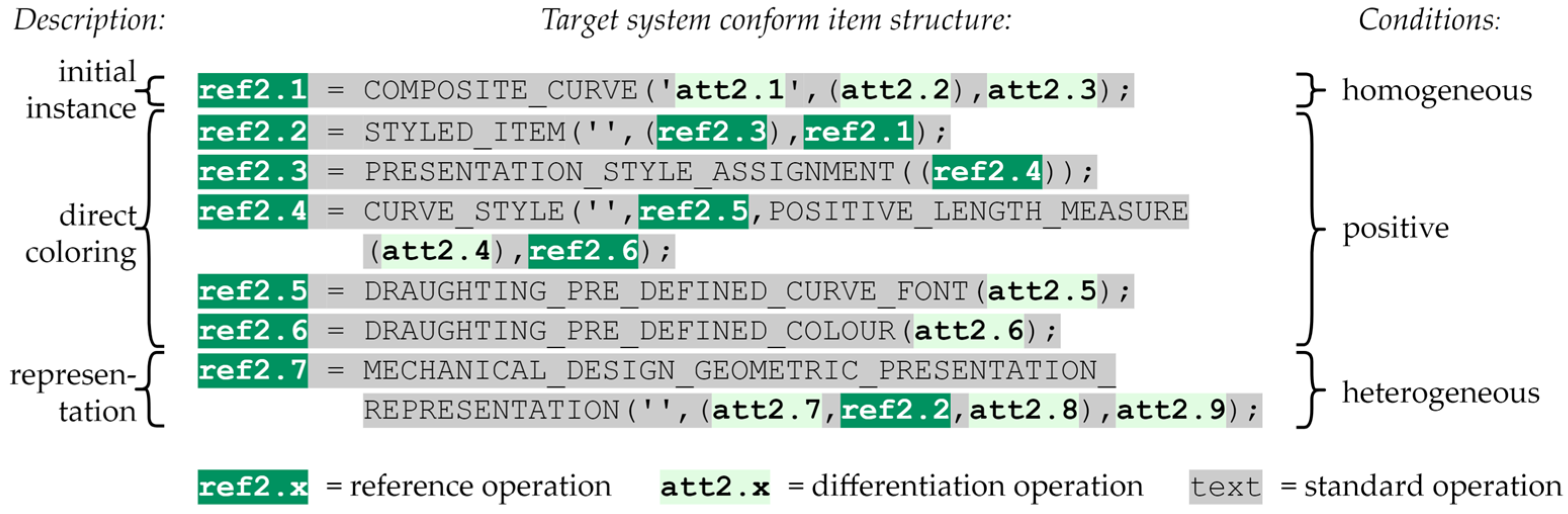
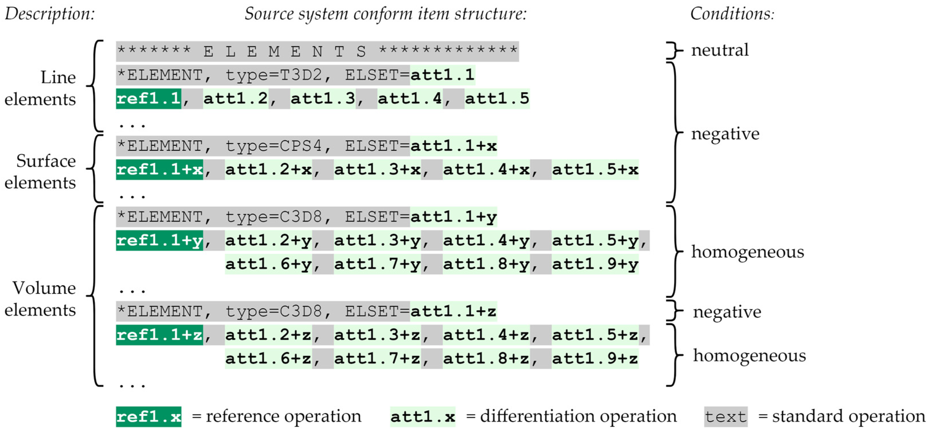
3.2.1. First Step—Definition of Universal Item Structures
- Reference operation—This is a part of an instance representing a key or reference within an item.
- Differentiation operation—This is a segment of an instance that describes attributes that vary across items.
- Standard operations—This is a part of an instance without any special meaning. It is a static string that does not differ across items, and standard operations serve as the basic framework.
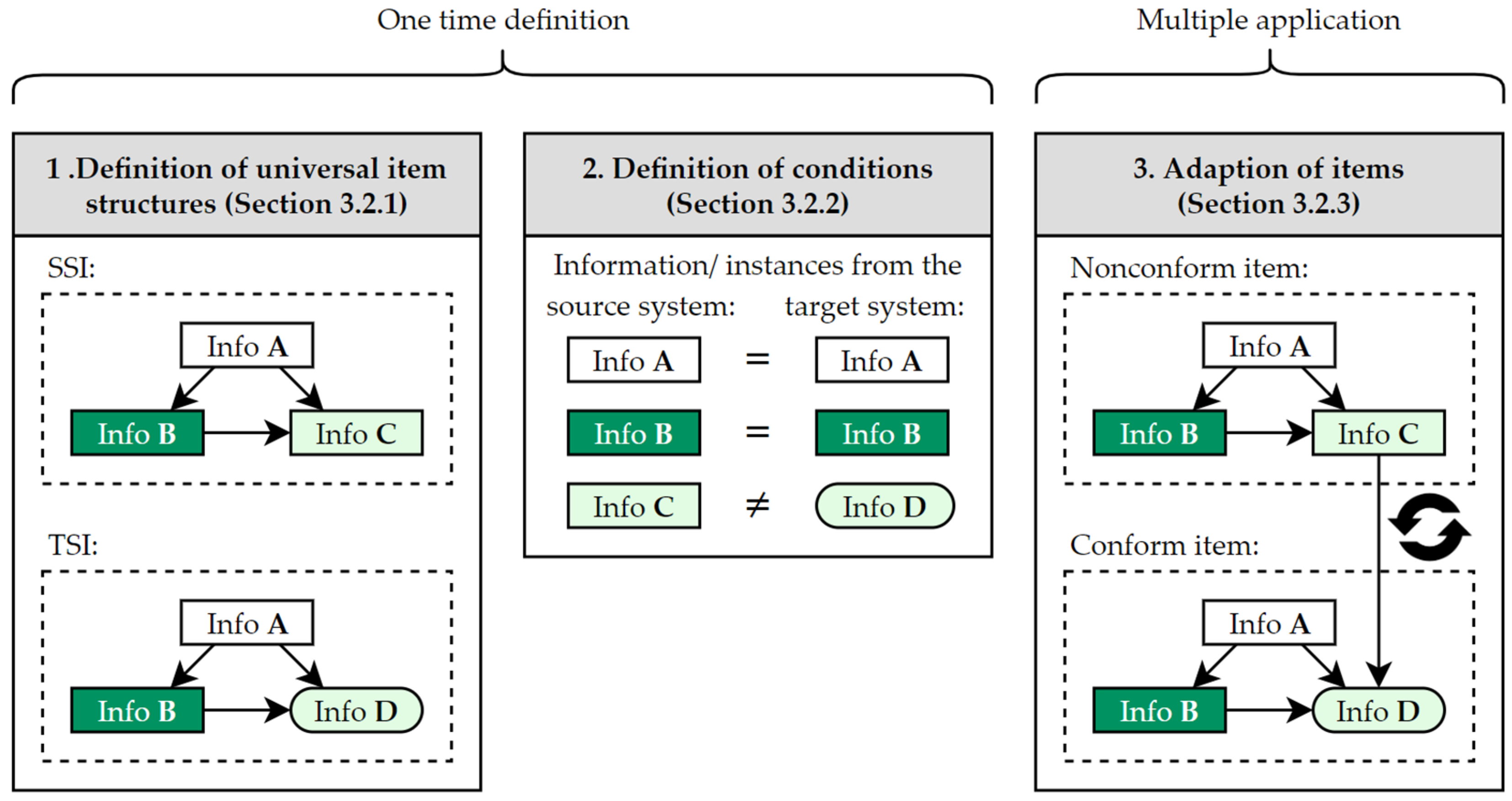
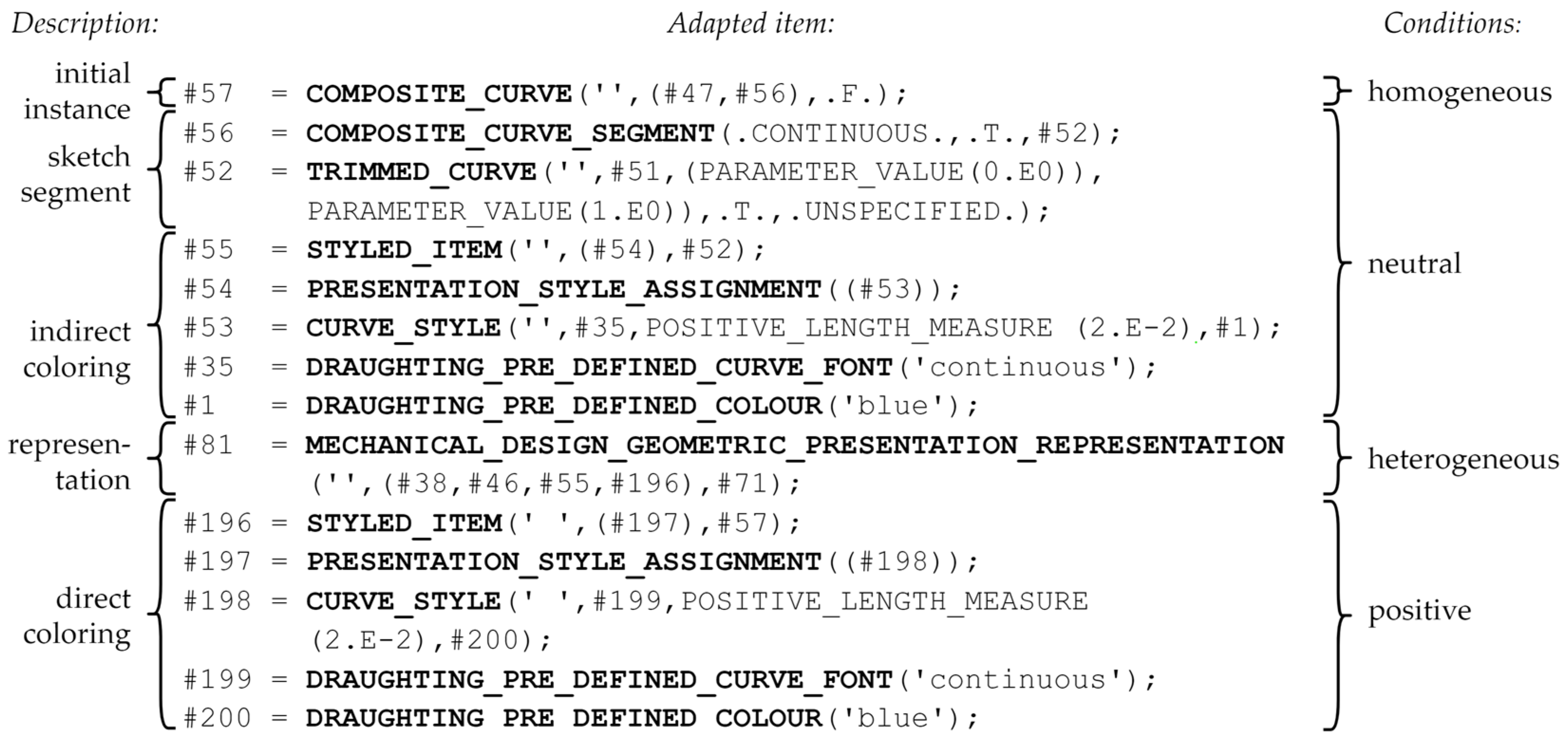
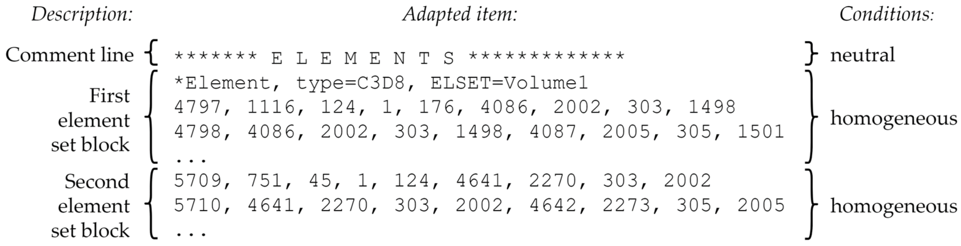
3.2.2. Second Step—Definition of Conditions
- Homogeneous—An instance is needed in the source and the target system to interpret correctly and is identical in both setups.
- Heterogeneous—An instance is present in both structures to be compared but differs in certain places. For example, a reference to another instance is missing.
- Positive—An instance only exists in the TSI, and this is necessary for an error-free import.
- Negative—An instance only exists in the SSI, and this leads to a misinterpretation in the target system.
- Neutral—An instance only exists in the SSI, and this does not lead to a misinterpretation in the target system.
3.2.3. Third Step—Adaptation of Items
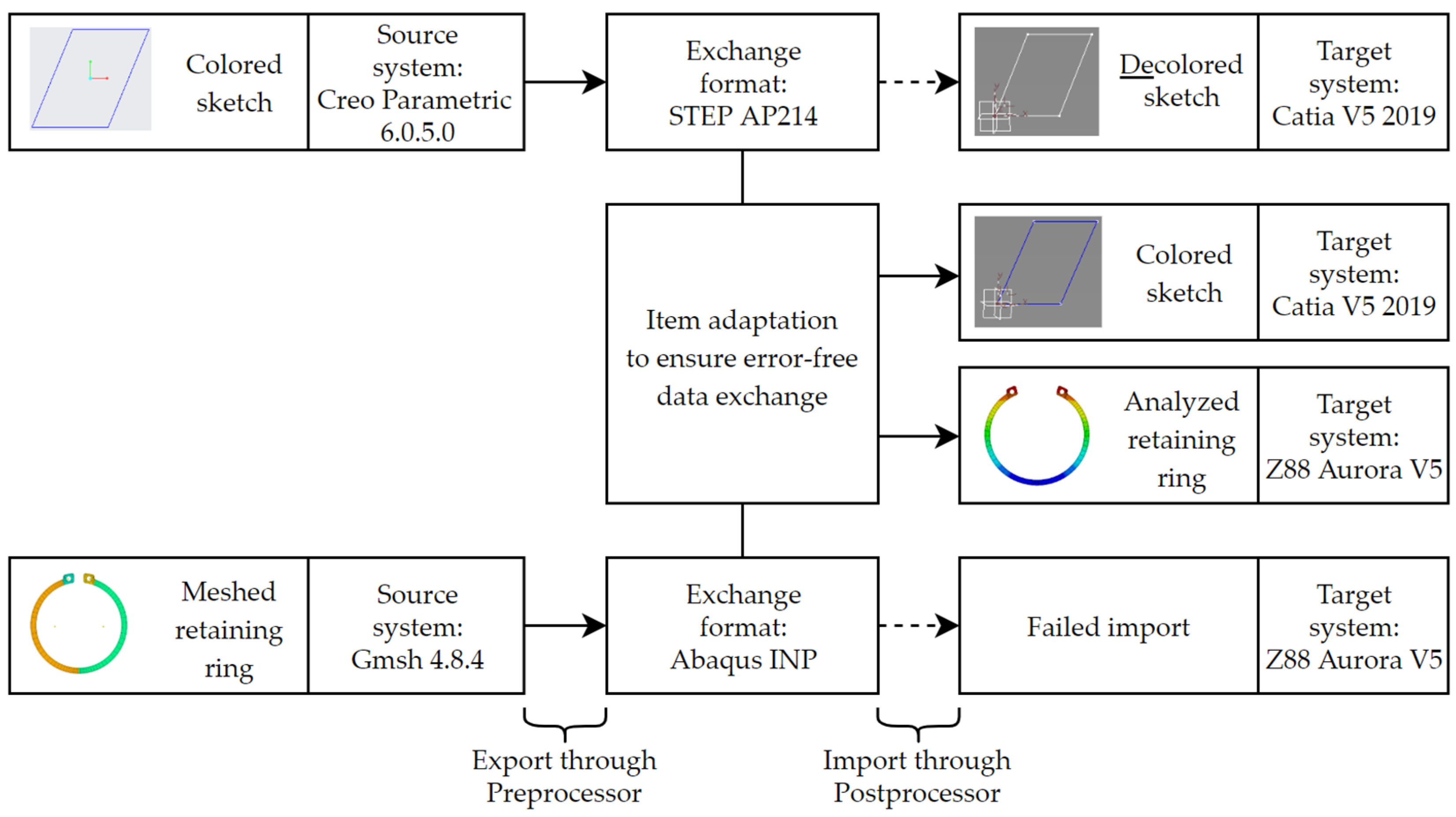
4. Case Studies
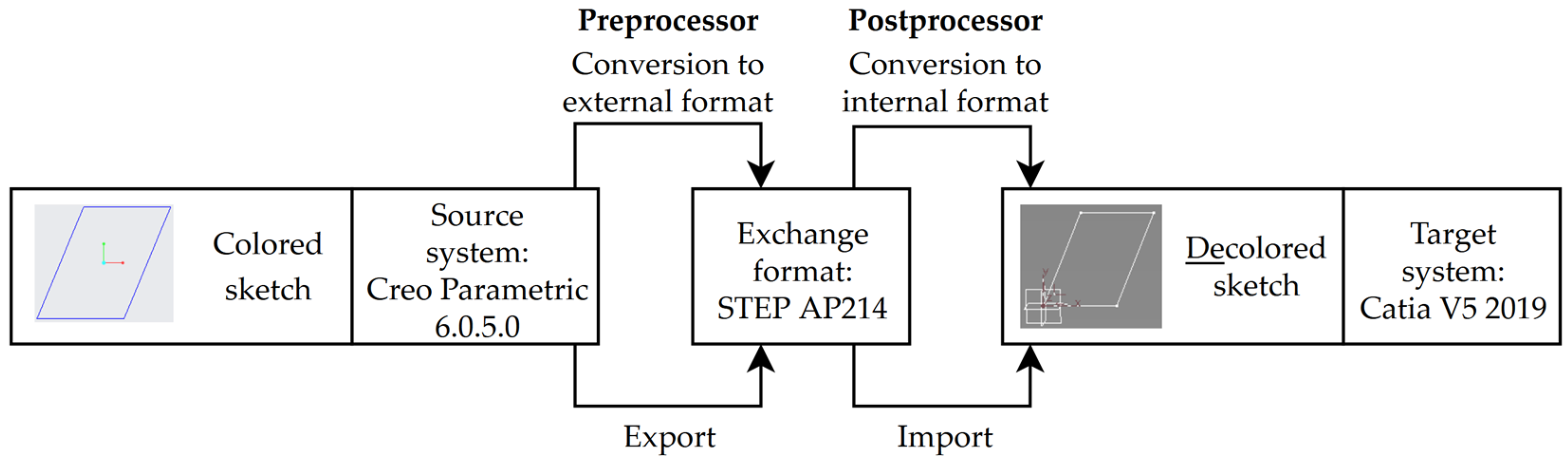
4.1. Sketch Exchange via STEP
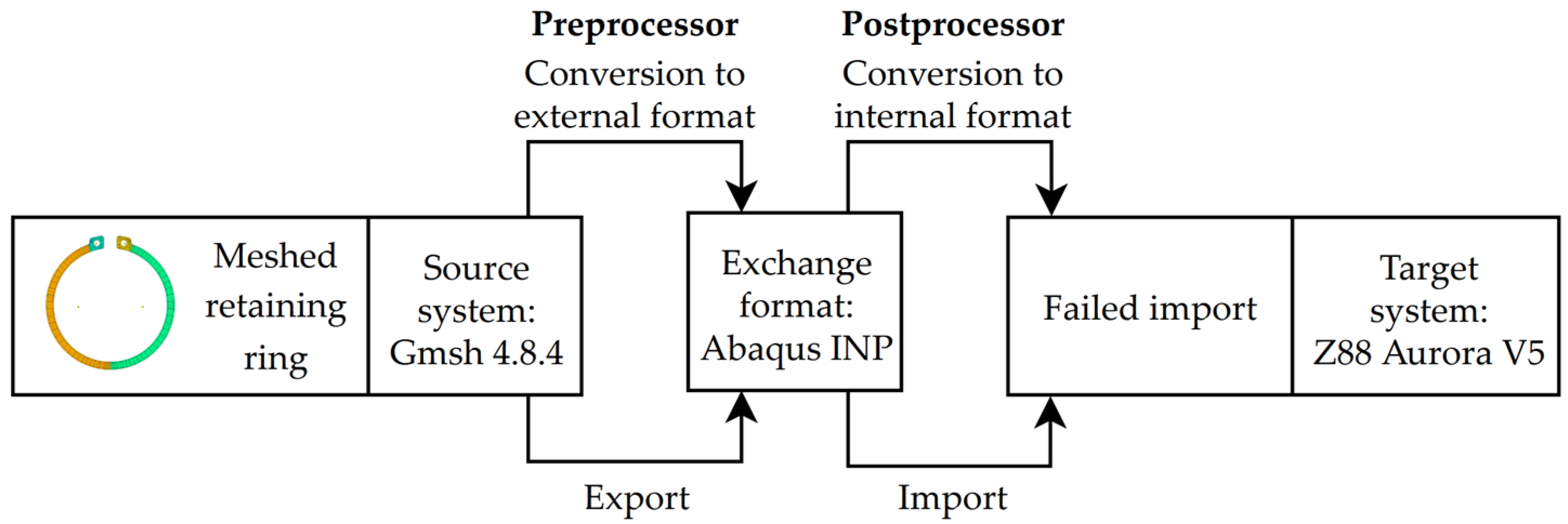
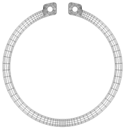
4.2. Retaining Ring Exchange via INP
5. Validation
6. Discussion
7. Conclusions
- Various norms, standards, and approaches uniform the exchange of data. Neutral file-based exchange is widely used, for example, in the context of tools, according to DIN 26100. The influences on data exchange and structure are manifold, which can be a source of compatibility problems. One primary influence is the different implementations of the routines in the pre- and postprocessors of the source and target systems involved during data transmission.
- A way to solve these transfer problems is to adapt information internally, directly at the file level, which minimizes the conversion process, as only necessary information is modified. Since compatibility problems are mostly context-dependent, heuristic-based methods are suitable for solving compatibility problems since the distinct issues can be described precisely.
- Specifying heuristics allows us to extract and adapt relevant objects with absolute certainty. A precise procedure is necessary because postprocessors usually require a unique data representation.
- A challenge, however, is that expert knowledge is necessary to specify the required rules, especially for complex items. Nevertheless, item adaptation is especially suitable for standard parts, such as tools, which are characterized by a relatively small number of features but a high number of variants.
Author Contributions
Funding
Institutional Review Board Statement
Informed Consent Statement
Data Availability Statement
Conflicts of Interest
References
- Liu, G.; Shah, R.; Schroeder, R.G. The relationships among functional integration, mass customisation, and firm performance. Int. J. Prod. Res. 2012, 50, 677–690. [Google Scholar] [CrossRef]
- Marks, P.; Yu, Q.; Weyrich, M. Survey on Flexibility and Changeability Indicators of automated Manufacturing Systems. In Proceedings of the 23rd International Conference on Emerging Technologies and Factory Automation (ETFA), Turin, Italy, 4–7 September 2018; IEEE: Piscataway, NJ, USA, 2018; pp. 516–523, ISBN 9781538671092. [Google Scholar]
- Anderl, R.; Haag, S.; Schützer, K.; Zancul, E. Digital twin technology—An approach for Industrie 4.0 vertical and horizontal lifecycle integration. Inf. Technol. 2018, 60, 125–132. [Google Scholar] [CrossRef]
- Gartner. Gartner 2018 Hype Cycle for IT in GCC Identifies Six Technologies That Will Reach Mainstream Adoption in Five to 10 Years. Available online: https://www.gartner.com/en/newsroom/press-releases/2018-12-13-gartner-2018-hype-cycle-for-it-in-gcc-identifies-six-technologies-that-will-reach-mainstream-adoption-in-five-to-10-years (accessed on 9 May 2022).
- Wilking, F.; Schleich, B.; Wartzack, S. Digital Twins—Definitions, Classes and Business Scenarios for Different Industry Sectors. Proc. Des. Soc. 2021, 1, 1293–1302. [Google Scholar] [CrossRef]
- VanDerHorn, E.; Mahadevan, S. Digital Twin: Generalization, characterization and implementation. Decis. Support Syst. 2021, 145, 113524. [Google Scholar] [CrossRef]
- Schleich, B.; Anwer, N.; Mathieu, L.; Wartzack, S. Shaping the digital twin for design and production engineering. CIRP Ann. 2017, 66, 141–144. [Google Scholar] [CrossRef]
- Schroeder, G.N.; Steinmetz, C.; Pereira, C.E.; Espindola, D.B. Digital Twin Data Modeling with AutomationML and a Communication Methodology for Data Exchange. IFAC-PapersOnLine 2016, 49, 12–17. [Google Scholar] [CrossRef]
- DIN German Institute for Standardization. DIN 26100:2021-05: Container File—Summary of Different Product Files for the Data Exchange; Beuth: Berlin, Germany, 2021. [Google Scholar]
- Tao, F.; Sui, F.; Liu, A.; Qi, Q.; Zhang, M.; Song, B.; Guo, Z.; Lu, S.C.-Y.; Nee, A.Y.C. Digital twin-driven product design framework. Int. J. Prod. Res. 2019, 57, 3935–3953. [Google Scholar] [CrossRef]
- Lee, J.; Lapira, E.; Bagheri, B.; Kao, H. Recent advances and trends in predictive manufacturing systems in big data environment. Manuf. Lett. 2013, 1, 38–41. [Google Scholar] [CrossRef]
- Gabor, T.; Belzner, L.; Kiermeier, M.; Beck, M.T.; Neitz, A. A Simulation-Based Architecture for Smart Cyber-Physical Systems. In Proceedings of the 2016 IEEE International Conference on Autonomic Computing (ICAC), Wuerzburg, Germany, 17–22 July 2016; IEEE: Piscataway, NJ, USA, 2016; pp. 374–379, ISBN 978-1-5090-1654-9. [Google Scholar]
- Courtney, R. Some Informal Comments About Integrity and the Integrity Workshop. In Proceedings of the International Workshop on Data Integrity, Gakhersburg, MD, USA, 25–27 January 1989; Ruthberg, Z.G., Polk, W.T., Eds.; National Institute of Standards and Technology: Gaithersburg, MD, USA, 1989; pp. 1–18. [Google Scholar]
- Sandhu, R.S. On five definitions of data integrity. In DBSec; Citeseer: University Park, PA, USA, 1994; pp. 257–267. [Google Scholar]
- Kleinschrodt, C. Analyse und Optimierung des Datenaustauschs von 3D-Modellen: Übertragung von CAD-Werkzeugmodellen mittels STEP. Ph.D. Thesis, University of Bayreuth, Bayreuth, Germany, 2019. [Google Scholar]
- ISO International Organization for Standardization. ISO 9000:2015: Quality Management Systems—Fundamentals and Vocabulary; Beuth Verlag GmbH: Berlin, Germany, 2015. [Google Scholar]
- Kleinschrodt, C.; Rieg, F. Einfluss der Modellierung auf die Austauschqualität von CAD-Modellen. Konstruktion 2020, 72. [Google Scholar] [CrossRef]
- Autodesk. DXF Reference. Available online: http://images.autodesk.com/adsk/files/autocad_2012_pdf_dxf-reference_enu.pdf (accessed on 9 August 2022).
- Abaqus. Abaqus Model Definition. Available online: https://abaqus-docs.mit.edu/2017/English/SIMACAEMODRefMap/simamod-c-model.htm (accessed on 5 May 2022).
- ISO International Organization for Standardization. Industrial Automation Systems and Integration—Product Data Representation and Exchange (ISO 10303): Part 1: Overview and Fundamental Principles; ISO: Geneva, Switzerland, 2021. [Google Scholar]
- Protégé. A free, Open-Souce Ontology Editor and Framework for Building Intelligent Systems. Available online: https://protege.stanford.edu/ (accessed on 21 July 2022).
- McGuinnes, D.L.; van Harmelen, F. OWL web ontology language overview. W3C 2004, 10, 2004. [Google Scholar]
- Barbau, R.; Krima, S.; Rachuri, S.; Narayanan, A.; Fiorentini, X.; Foufou, S.; Sriram, R.D. OntoSTEP: Enriching product model data using ontologies. Comput. Aided Des. 2012, 44, 575–590. [Google Scholar] [CrossRef]
- Chaparala, R.T.; Hartman, N.W.; Springer, J. Examining CAD Interoperability through the Use of Ontologies. Comput. Aided Des. Appl. 2013, 10, 83–96. [Google Scholar] [CrossRef]
- Qin, Y.; Lu, W.; Qi, Q.; Liu, X.; Zhong, Y.; Scott, P.J.; Jiang, X. Status, Comparison, and Issues of Computer-Aided Design Model Data Exchange Methods Based on Standardized Neutral Files and Web Ontology Language File. J. Comput. Inf. Sci. Eng. 2017, 17, 010801-1–010801-8. [Google Scholar] [CrossRef]
- Ramnath, S.; Haghighi, P.; Venkiteswaran, A.; Shah, J.J. Interoperability of CAD geometry and product manufacturing information for computer integrated manufacturing. Int. J. Comput. Integr. Manuf. 2020, 33, 116–132. [Google Scholar] [CrossRef]
- Li, H.; Lu, J.; Zheng, X.; Guoxin, W.; Dimitris, K. Supporting Digital Twin Integration Using Semantic Modeling and High-Level Architecture. In Advances in Production Management Systems, Artificial Intelligence for Sustainable and Resilient Production Systems; Dolgui, A., Bernard, A., Lemoine, D., von Cieminski, G., Romero, D., Eds.; Springer International Publishing: Cham, Switzerland, 2021; pp. 228–236. ISBN 978-3-030-85909-1. [Google Scholar]
- Klein, M.; Maschler, B.; Zeller, A.; Tallkhestani, A.; Jazdi, N.; Rosen, R.; Weyrich, M. Architektur und Technologiekomponenten eines digitalen Zwillings. In Proceedings of the VDI-Kongress Automation, Baden-Baden, Germany, 2–3 July 2019; pp. 89–102. [Google Scholar]
- Nasr, E.A.; Kamrani, A.K. Computer-Based Design and Manufacturing: An Information-Based Approach; Springer: New York, NY, USA, 2007; ISBN 0-387-23323-7. [Google Scholar]
- Rao, P.N. CAD/CAM—Principles and Applications, 2nd ed.; Tata McGraw-Hill: New Delhi, India, 2004; ISBN 0-07-058373-0. [Google Scholar]
- Babic, B.; Nesic, N.; Miljkovic, Z. A review of automated feature recognition with rule-based pattern recognition. Comput. Ind. 2008, 59, 321–337. [Google Scholar] [CrossRef]
- Shi, Y.; Zhang, Y.; Xia, K.; Harik, R. A Critical Review of Feature Recognition Techniques. Comput. Aided Des. Appl. 2020, 17, 861–899. [Google Scholar] [CrossRef]
- Yeo, C.; Kim, B.C.; Cheon, S.; Lee, J.; Mun, D. Machining feature recognition based on deep neural networks to support tight integration with 3D CAD systems. Sci. Rep. 2021, 11, 22147. [Google Scholar] [CrossRef]
- Shah, J.J.; Anderson, D.; Kim, Y.S.; Joshi, S. A Discourse on Geometric Feature Recognition from CAD Models. J. Comput. Inf. Sci. Eng. 2001, 1, 41–51. [Google Scholar] [CrossRef]
- Joshi, S.; Chang, T.C. Graph-based heuristics for recognition of machined features from a 3D solid model. Comput. Aided Des. 1988, 20, 58–66. [Google Scholar] [CrossRef]
- Marefat, M.; Kashyap, R.L. Geometric reasoning for recognition of three-dimensional object features. IEEE Trans. Pattern Anal. Mach. Intell. 1990, 12, 949–965. [Google Scholar] [CrossRef]
- Holland, P.; Standring, P.; Long, H.; Mynors, D. Feature extraction from STEP (ISO 10303) CAD drawing files for metalforming process selection in an integrated design system. J. Mater. Process. Technol. 2002, 125-126, 446–455. [Google Scholar] [CrossRef]
- Tan, C.F.; Kher, V.K.; Ismail, N. Design of a Feature Recognition System for CAD/CAM Integration. World Appl. Sci. J. 2013, 21, 1162–1166. [Google Scholar] [CrossRef]
- Malleswaria, V.N.; Vallib, P.M. Automatic Recognition of Machining Features using STEP Files. Int. J. Eng. Res. Technol. 2013, 2, 1–11. [Google Scholar]
- Vandenbrande, J.H.; Requicha, A. Spatial reasoning for the automatic recognition of machinable features in solid models. IEEE Trans. Pattern Anal. Mach. Intell. 1993, 15, 1269–1285. [Google Scholar] [CrossRef]
- Regli, W.C.; Gupta, S.K.; Nau, D.S. Extracting alternative machining features: An algorithmic approach. Res. Eng. Des. 1995, 7, 173–192. [Google Scholar] [CrossRef]
- Sivakumar, S.; Dhanalakshmi, V. An approach towards the integration of CAD/CAM/CAI through STEP file using feature extraction for cylindrical parts. Int. J. Comput. Integr. Manuf. 2013, 26, 561–570. [Google Scholar] [CrossRef]
- Babić, B.R.; Nešić, N.; Miljković, Z. Automatic feature recognition using artificial neural networks to integrate design and manufacturing: Review of automatic feature recognition systems. Artif. Intell. Eng. Des. Anal. Manuf. 2011, 25, 289–304. [Google Scholar] [CrossRef]
- Zhang, D.; He, F.; Tu, Z.; Zou, L.; Chen, Y. Pointwise geometric and semantic learning network on 3D point clouds. ICA 2019, 27, 57–75. [Google Scholar] [CrossRef]
- Wildgrube, E. Datenformat. In Lexikon der Informatik und Datenverarbeitung, 3rd ed.; Schneider, H.-J., Ed.; Oldenbourg: München, Germany, 1991; pp. 187–188. ISBN 3-486-21514-0. [Google Scholar]
- Klein, J. Datenintegrität in Heterogenen Informationssystemen: Ereignisorientierte Aktualisierung globaler Datenredundanzen, 1st ed.; Deutscher Universitätsverlag: Wiesbaden, Germany, 1992; ISBN 978-3824401079. [Google Scholar]
- Heidenhain. User’s Manual Conversational Programming. Available online: https://content.heidenhain.de/doku/tnc_guide/pdf_files/TNC400/286180-xx/bhb/291_016-24.pdf (accessed on 25 January 2022).
- DIN German Institute for Standardization. DIN 4000-102:2021-05: Tabular Layouts of Properties—Part 102: Data Exchange for Tabular Layouts of Properties with XML Schema; Beuth: Berlin, Germany, 2021. [Google Scholar]
- Anderl, R.; Trippner, D. STEP STandard for the Exchange of Product Model Data: Eine Einführung in die Entwicklung, Implementierung und industrielle Nutzung der Normenreihe ISO 10303 (STEP), 1st ed.; Teubner: Stuttgart, Germany; Leipzig, Germany, 2000; ISBN 978-3-519-06377-3. [Google Scholar]
- ISO International Organization for Standardization. Industrial Automation Systems and Integration—Product Data Representation and Exchange (ISO 10303): Part 214: Application Protocol: Core Data for Automotive Mechanical Design Processes; ISO: Geneva, Schwitzerland, 2010. [Google Scholar]
- ISO International Organization for Standardization. Industrial Automation Systems and Integration—Product Data Representation and Exchange (ISO 10303): Part 21: Implementation Methods: Clear Text Encoding of the Exchange Structure; ISO: Geneva, Schwitzerland, 2002. [Google Scholar]
- Abaqus. Characterizing Elements. Available online: https://abaqus-docs.mit.edu/2017/English/SIMACAEELMRefMap/simaelm-c-general.htm (accessed on 5 May 2022).
- Abaqus. Input Syntax Rules. Available online: https://abaqus-docs.mit.edu/2017/English/SIMACAEMODRefMap/simamod-c-inputsyntax.htm (accessed on 4 May 2022).
- Kleinschrodt, C.; Rieg, F. Normalisation of STEP files for improving the data compatibility of transferred tool models. Tech. Gaz. 2017, 5, 201–205. [Google Scholar] [CrossRef]
- Nagy, Z. Regex Quick Syntax Reference: Understanding and Using; Apress: Berkeley, CA, USA, 2018; ISBN 978-1-4842-3875-2. [Google Scholar]
- DIN German Institute for Standardization. DIN 4000-81:2017-09: Tabular Layouts of Properties—Part 81: Drills and Countersinking Tools with Non-Indexable Cutting Edges; Beuth: Berlin, Germany, 2017. [Google Scholar]
- Gmsh. A Three-Dimensional Finite Element Mesh Generator with Built-In Pre- and Post-Processing Facilities. Available online: https://gmsh.info/ (accessed on 4 May 2022).
- LSCAD. Z88AURORA. Available online: https://en.z88.de/z88aurora/ (accessed on 6 May 2022).
- Mohr, J.; Kleinschrodt, C.; Diwisch, P.; Rieg, F. Betrachtung von Konfigurationsdateiformaten und GUI-Frameworks für Programme zur Aufbereitung von Austauschdateien. In Proceedings of the 18th Gemeinsames Kolloquium Konstruktionstechnik: Nachhaltige Produktentwicklung, Duisburg, Germany, 1–2 October 2020; Corves, B., Gericke, K., Grote, K.-H., Lohrengel, A., Löwer, M., Nagarajah, A., Rieg, F., Scharr, G., Stelzer, R., Eds.; University of Duisburg-Essen: Duisburg, Germany, 1718. [Google Scholar] [CrossRef]
- Mohr, J.; Kleinschrodt, C.; Siegel, T.; Rieg, F. Entwicklung einer Beschreibungssprache zur Analyse und Behebung von Datenaustauschproblemen. In Proceedings of the 17th Gemeinsames Kolloquium Konstruktionstechnik: Agile Entwicklung physischer Produkte, Aachen, Germany, 1–2 October 2019; Corves, B., Gericke, K., Grote, K.-H., Lohrengel, A., Müller, N., Nagarajah, A., Rieg, F., Scharr, G., Stelzer, R., Eds.; RWTH Aachen: Aachen, Germany. [Google Scholar] [CrossRef]
- Mohr, J.; Kleinschrodt, C.; Zimmermann, M.; Rieg, F. Konzeptionelles Design zur softwaregestützten Analyse und Modifikation von Produktdaten. In Proceedings of the 16th Gemeinsames Kolloquium Konstruktionstechnik: Digitalisierung und Produktentwicklung, Bayreuth, Germany, 11–12 October 2018; Brökel, K., Corves, B., Grote, K.-H., Lohrengel, A., Müller, N., Nagarajah, A., Rieg, F., Scharr, G., Stelzer, R., Eds.; University of Bayreuth: Bayreuth, Germany, 2018. ISBN 978-3-00-059609-4. [Google Scholar]
- DIN German Institute for Standardization. DIN 4003-87:2021-10: Concept for the Design of 3D Models Based on Properties According to DIN 4000—Part 87: End Mills for Indexable Inserts; Beuth: Berlin, Germany, 2021. [Google Scholar]
- DIN German Institute for Standardization. DIN 4003-126:2012-10: Concept for the Design of 3D Models Based on Properties According to DIN 4000—Part 126: Reamers with Non-Indexable Cutting Edges; Beuth: Berlin, Germany, 2012. [Google Scholar]
- DIN German Institute for Standardization. DIN 471: Retaining Rings for Shafts—Normal Type and Heavy Type; Beuth: Berlin, Germany, 2011. [Google Scholar]
- Martin, D. What Does MBD Mean? Available online: https://www.ptc.com/en/blogs/cad/what-does-mbd-mean (accessed on 18 April 2022).
- Miller, A.M.; Alvarez, R.; Hartman, N. Towards an extended model-based definition for the digital twin. Comput. Aided Des. Appl. 2018, 15, 880–891. [Google Scholar] [CrossRef]


| File Format | Area of Use | Ordinary Encoding |
|---|---|---|
| AVI | Multimedia | Binary |
| DXF | 2D-documentation, -graphics, -contours | Text |
| GSD, TXT | General descriptions | Text |
| H, I | Computer numerical control (CNC) programming | Text |
| IO | General descriptions | Binary |
| JPG, PNG | Image, sketch, multimedia | Binary |
| JT | 3D-representations—detailed and basic | Binary |
| NC | CNC programming | Binary |
| P21 | ISO properties | Text |
| Catalog data, 2D-documentation | Binary | |
| STEP, STL, INP | 3D-representations (detailed and basic) | Text |
| XML | International Standards Organization (ISO) and DIN properties, general descriptions, catalog data, documentation, application data | Text |
| Reference Type | Schematic Representation | File Format | Exemplary Area of Use | Exemplary Item |
|---|---|---|---|---|
| Hierarchy |  | XML | General Description | Product feature |
| Relation |  | STEP | 3D-representations | Coordinate system |
| Block | 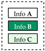 | H | CNC programming | Drill hole |
| Classification | Model in CATIA without Previous Item Adaption | Model in CATIA with Previous Item Adaption |
|---|---|---|
| T-slot cutter according to DIN 4003-87 [62] (excerpt) | 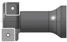 |  |
| Step reamer according to DIN 4003-126 [63] | 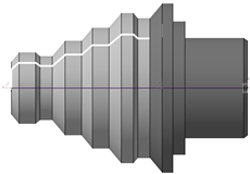 |  |

Publisher’s Note: MDPI stays neutral with regard to jurisdictional claims in published maps and institutional affiliations. |
© 2022 by the authors. Licensee MDPI, Basel, Switzerland. This article is an open access article distributed under the terms and conditions of the Creative Commons Attribution (CC BY) license (https://creativecommons.org/licenses/by/4.0/).
Share and Cite
Mohr, J.; Kleinschrodt, C.; Tremmel, S.; Rieg, F. Compatibility Improvement of Interrelated Items in Exchange Files—A General Method for Supporting the Data Integrity of Digital Twins. Appl. Sci. 2022, 12, 8099. https://doi.org/10.3390/app12168099
Mohr J, Kleinschrodt C, Tremmel S, Rieg F. Compatibility Improvement of Interrelated Items in Exchange Files—A General Method for Supporting the Data Integrity of Digital Twins. Applied Sciences. 2022; 12(16):8099. https://doi.org/10.3390/app12168099
Chicago/Turabian StyleMohr, Johannes, Claudia Kleinschrodt, Stephan Tremmel, and Frank Rieg. 2022. "Compatibility Improvement of Interrelated Items in Exchange Files—A General Method for Supporting the Data Integrity of Digital Twins" Applied Sciences 12, no. 16: 8099. https://doi.org/10.3390/app12168099
APA StyleMohr, J., Kleinschrodt, C., Tremmel, S., & Rieg, F. (2022). Compatibility Improvement of Interrelated Items in Exchange Files—A General Method for Supporting the Data Integrity of Digital Twins. Applied Sciences, 12(16), 8099. https://doi.org/10.3390/app12168099