Communication

Optimal Design and Experiment of Manipulator for Camellia Pollen Picking

College of Mechanical and Electrical Engineering, Central South University of Forestry and Technology, Changsha 410004, China
*
Author to whom correspondence should be addressed.
Appl. Sci. 2022, 12(16), 8011; https://doi.org/10.3390/app12168011
Submission received: 18 July 2022 / Revised: 6 August 2022 / Accepted: 8 August 2022 / Published: 10 August 2022
(This article belongs to the Section Mechanical Engineering)

Abstract

:
In this paper, a four-degree-of-freedom camellia-pollen-picking manipulator is proposed and designed. It can solve the problem of having no mechanized equipment for picking camellia pollen in agricultural machinery as the labor intensity of manual pollen extraction is high. To make the manipulator reach the target space quickly and efficiently, a structural-parameter-optimization method that reduces the working space to a more versatile cube is proposed. The numerical optimization algorithm is used to calculate the optimization result. Through the static analysis of the manipulator, the stability of the manipulator structure is verified. The working space of the manipulator is simulated and analyzed, and the simulation results are further verified by experiments. This research provides reliable technical support for the structural optimization, manufacturing, and intelligent upgrading of the camellia-pollen-picking robot.

1. Introduction

Camellia is an important woody oil species in China. The pollination habit of camellia directly affects the yield of camellia. Camellia pollen is self-incompatible, and the fruit-setting rate of camellia under natural conditions is about 12%. The fruit-setting rate of camellia could be greatly increased by artificial pollination [1,2,3,4].
Forestry robots are the main force for the rapid development of forestry production. At present, picking robots have achieved a certain degree of automation in the harvesting of camellia and other economic forest and fruit crops. Some universities, such as Nanjing Forestry University and Central South University of Forestry and Technology, are researching forestry-picking robots [5,6,7]. Based on the previous research, the pollination of economic forest crops is mostly carried out by spraying with drones. Considering that a large amount of pollen is required for spreading using drones, and considering the low efficiency of manual pollination, this paper examines and designs a pollen-picking robotic arm, which can complete the pollen-picking operation by installing end effectors. Other end effectors can also be replaced to complete pollination, pruning, and spraying. The prototype machine is processed, and the workability of the working space of the camellia-pollen-picking manipulator is tested. It lays a solid foundation for loading the pollen-harvesting end effector [8], further improving the work efficiency of camellia-pollen harvesting, while addressing the need for mechanized pollen-picking equipment in China.
There are few in-depth studies on the structural design of the manipulator because most of the research on picking robots focuses on the recognition and positioning of the target fruit by the vision system. Japan Konto et al. developed a 7-DOF tomato-picking robot [9], which has multiple degrees of freedom and a complex structure; then he studied a 6-DOF cucumber-picking robot [10], and the structure was not optimized. Researchers at the Beijing University of Technology in China developed a tomato-picking robot [11], focusing on the automatic navigation system and binocular visual recognition and positioning, but they did not discuss the structure optimization of the manipulator in depth. Researchers at Shandong Agricultural University in China mainly studied the identification and positioning of strawberries [12]. For the structural design of the strawberry-picking manipulator, the workspace and optimal design of the manipulator were not studied.
The structural design and parameter optimization of the manipulator impact its workspace, movement flexibility, and stability. In this paper, a four-degree-of-freedom serial manipulator is designed, a general manipulator structural parameter optimization method is proposed for the picking area as a canopy globe, and the optimization method is verified by experiments. The static analysis of the manipulator is carried out to verify the stability of the manipulator structure. The working space of the manipulator is simulated and analyzed, and the simulation results are further verified by experiments.

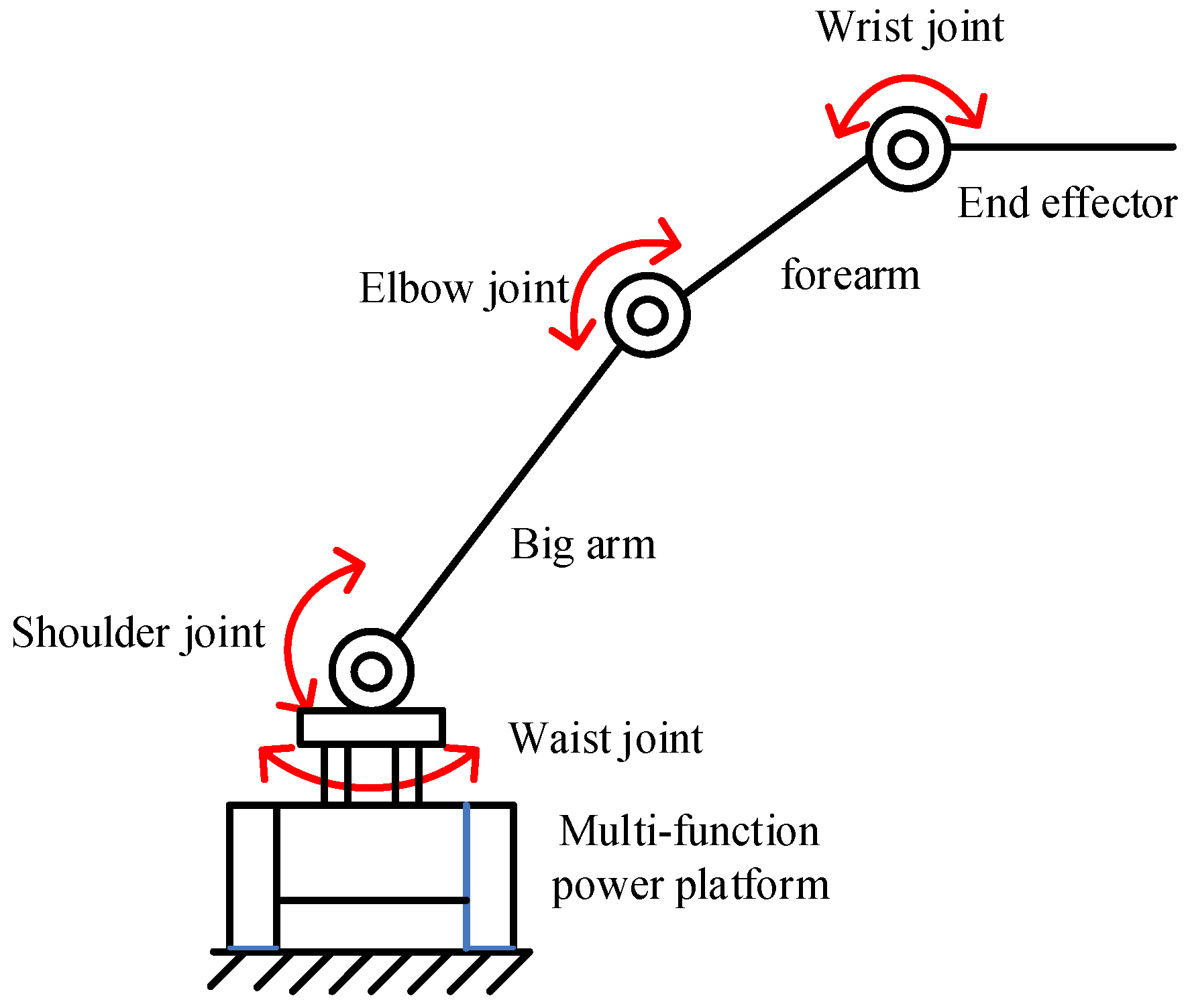
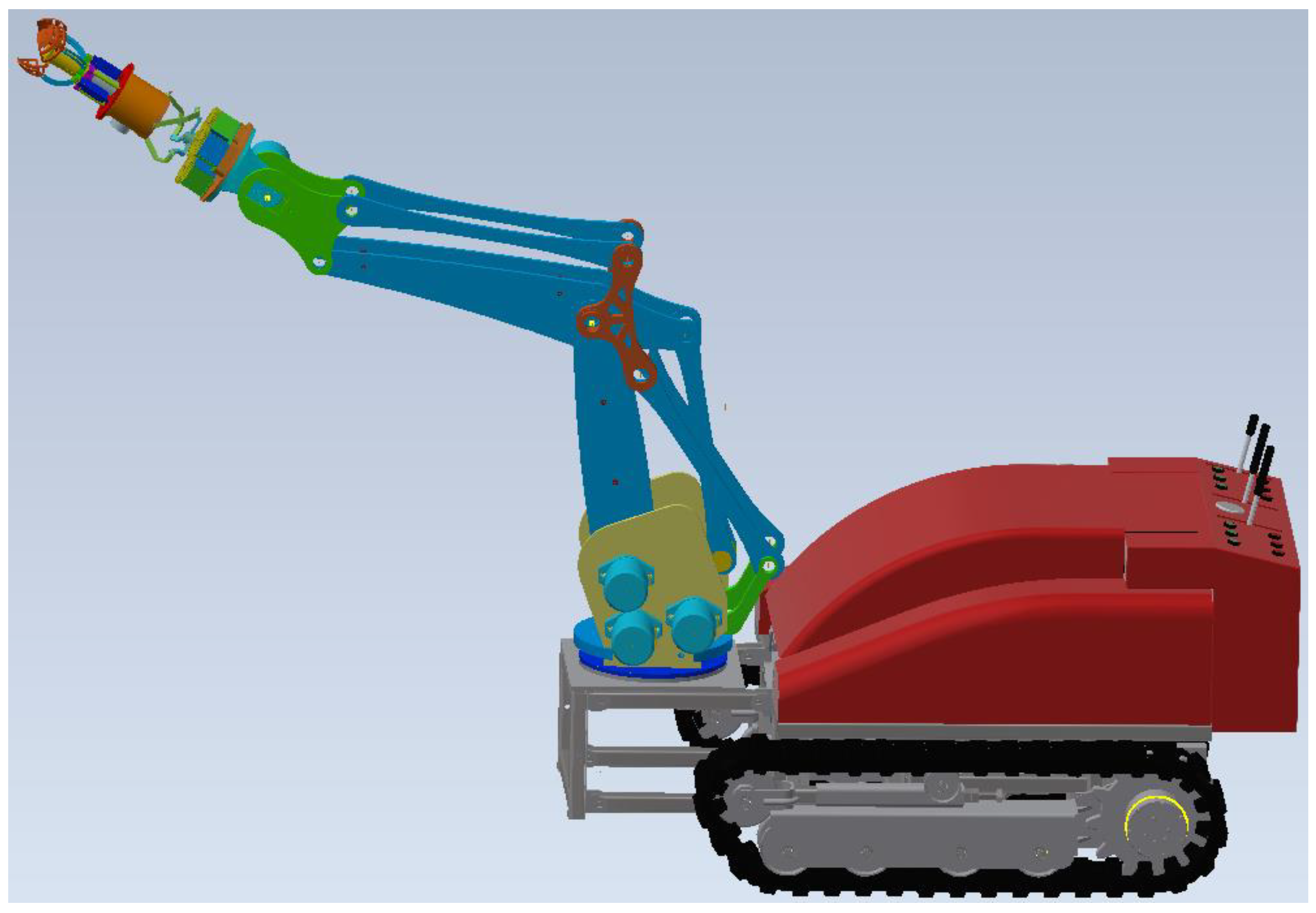
2. Structural Design of the Manipulator for Camellia Pollen Picking

The manipulator is the primary execution component to realize the pollen-picking operation. The structural design of the manipulator will impact its working space for pollen picking as well as its movement flexibility and stability, which plays a decisive role in the realization of the entire intelligent pollen-picking function [13,14,15,16,17,18,19]. In this paper, the camellia-pollen-picking manipulator adopts a joint-type serial mechanism. The schematic diagram of the mechanism is shown in Figure 1.
Figure 2 shows a 3D drawing of the pollen-picking robot. The base of the big arm is installed on the multi-function power platform, and the front end of the forearm is installed with a three-claw linkage-type end effector. The end effector collects pollen by means of “cutting-air suction” and transports it to the collection vessel through the pipeline. This paper mainly designs the mechanical arm, which adopts the multi-CPU and distributed-control mode. The upper computer is responsible for system management and trajectory planning. The lower computer is composed of multiple CPUs, and each CPU controls a joint movement. The upper computer and the lower computer communicate through CAN bus. The multi-function power platform, the end effector, and the pneumatic conveying pipeline are not introduced in detail.
When the joint-type serial manipulator collects pollen, three movement degrees of freedom are required to determine any position of the end effector in the three-dimensional space. One rotational degree of freedom is needed to determine the arbitrary posture of the end effector. The end effector adopts an internal rotary actuator. The degree of freedom of rotation for picking pollen is not included in the degrees of freedom of the manipulator. To meet the rigidity and ample execution space of the pollen-picking manipulator, a serial manipulator with four degrees of freedom is selected.
According to the revised G-K degree-of-freedom-calculation formula, the degrees of freedom of the serial mechanism are obtained as:
M = d ( n g 1 ) + i = 1 g f i + υ ζ = 6 × ( 4 4 1 ) + ( 3 × 3 + 1 × 1 ) + 0 0 = 4
In the formula:
  • M—The number of degrees of freedom of the organization;
  • d—The order of the mechanism; the space mechanism is of the 6th order;
  • n—The total number of components in the mechanism, including the rack;
  • g—The number of kinematic pairs in the organization;
  • fi—The number of degrees of freedom of the i-th kinematic pair;
  • υ—Redundant degrees of freedom of the mechanism;
  • ζ—The number of local degrees of freedom.

3. Optimal Design of the Manipulator for Camellia Pollen Picking

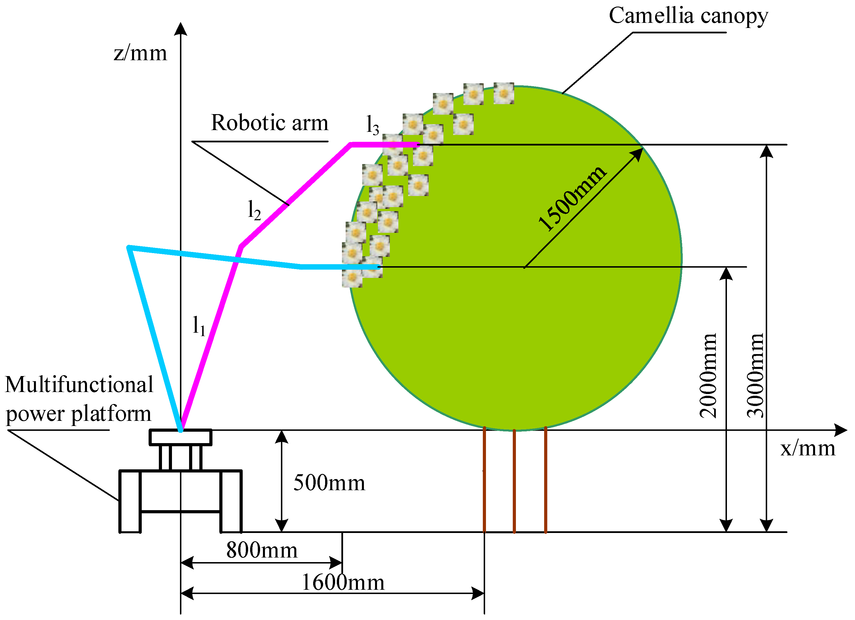
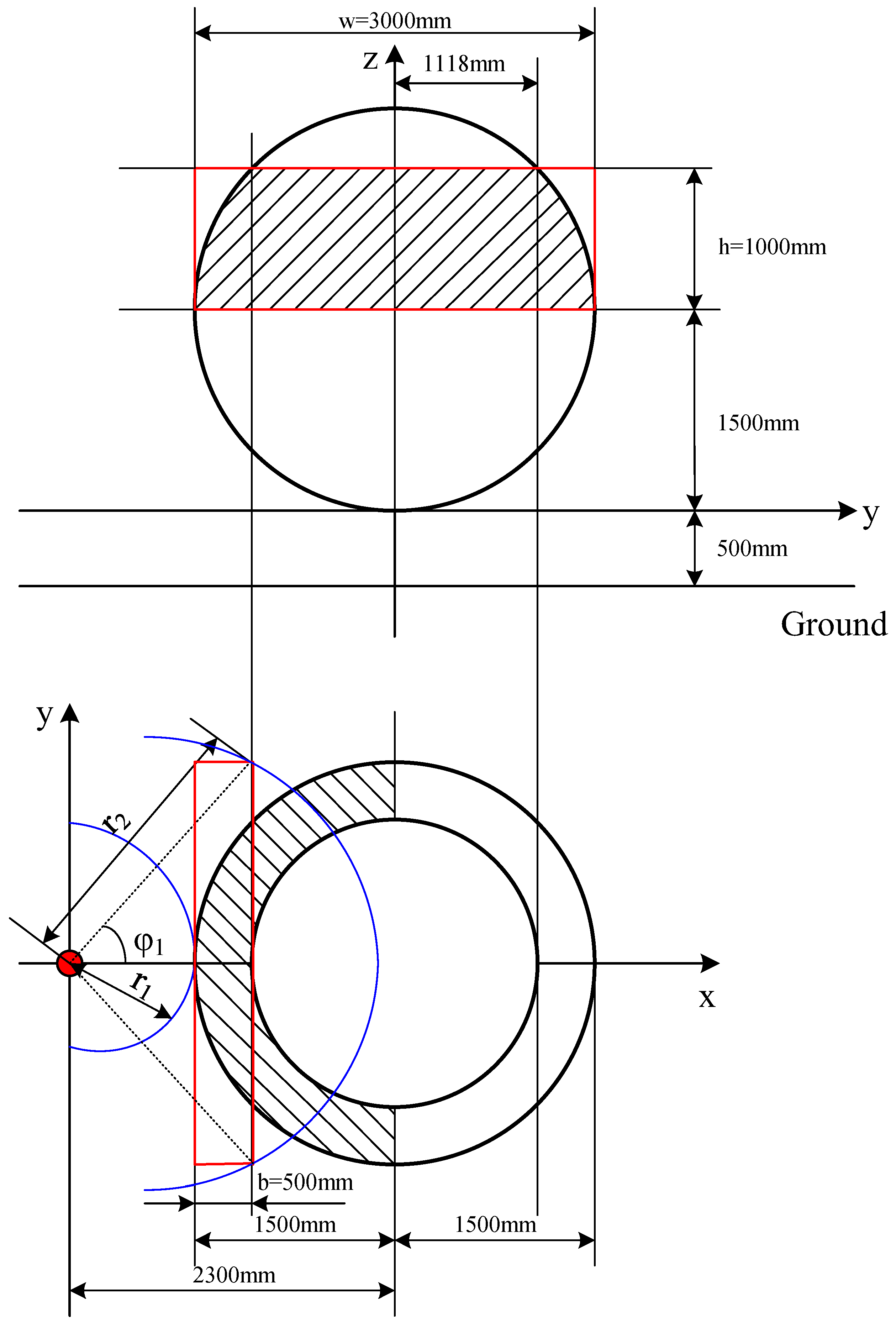
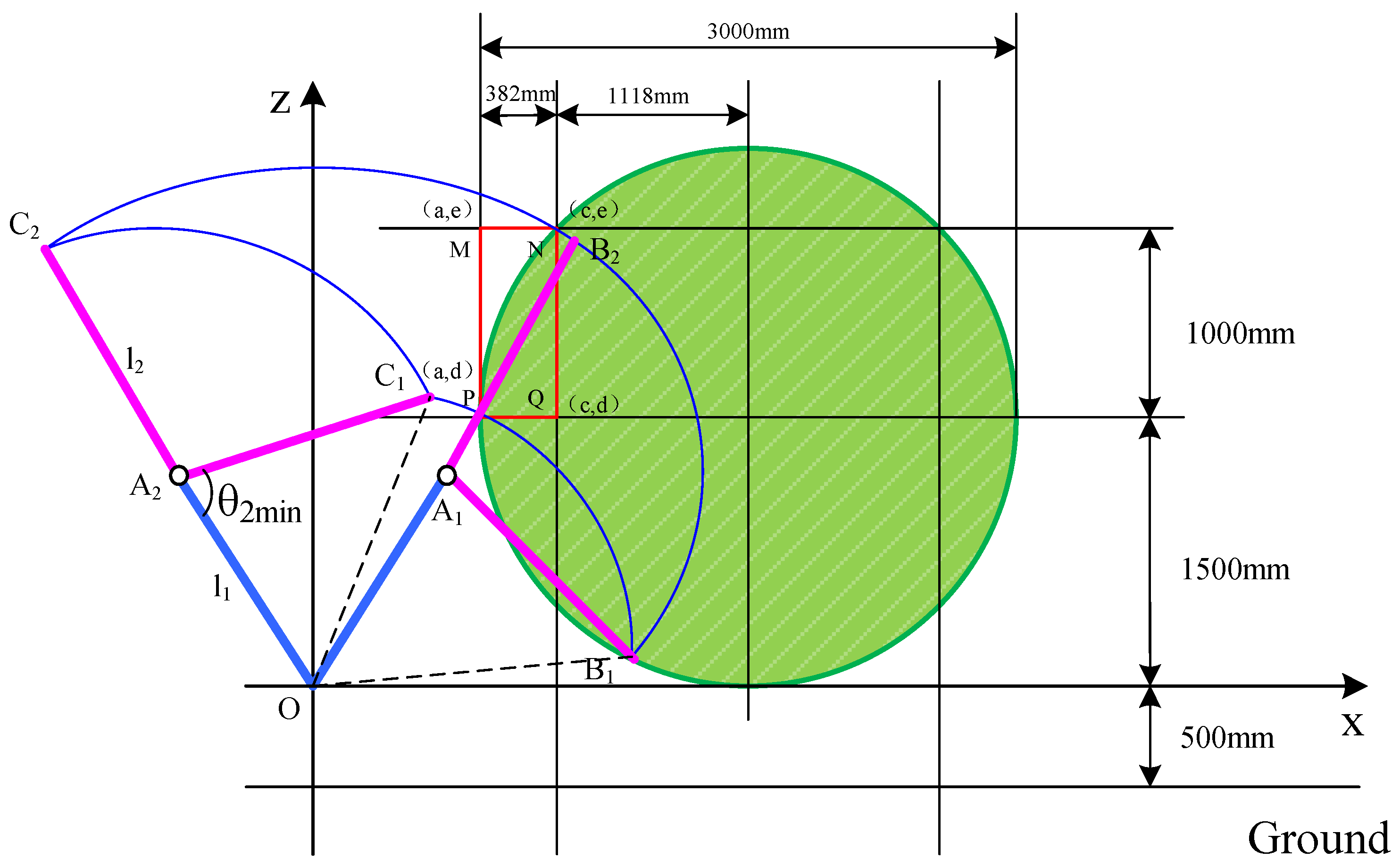
3.1. Simplified Processing of Picking Space

The working space of the robot is determined by the primary linkage system. The primary linkage system consists of three degrees of freedom determined by the base, the big arm, and the forearm. The structural parameters of the exact pollen-picking manipulator are mainly determined by the geometric length and rotation range of the main connecting rod. The size is as small as possible for meeting the requirements of the working area. The forearm adopts a parallel mechanism to ensure the final angle of the moving platform.
After the new camellia forest is uniformly reshaped, the target picking space is the upper half of the globe, and the diameter of the globe is r = 1500   mm . To preserve the vigor of the camellia tree after pollen picking, only the pollen within the height range of 2/3 from the top in the upper hemisphere area are picked. Considering the width of the machine-plowing road and the requirements of the camellia-pollen-picking operation, the camellia-pollen-picking manipulator is placed on the multi-functional pollen platform with a height of 1m, and the camellia flowers in the target picking area are distributed 800–1600 mm from the center of the robot vehicle. The height is 2000–3000 mm, and the depth is −300–300 mm when the pollen-picking robot travels along the plowing road in the east–west direction. The front view of the pollen-picking robot and the target picking area is shown in Figure 3.
The picking area is an incomplete globe, and the target picking area is now simplified [20,21,22,23,24]. The working space of the manipulator end effector is enlarged to form a cube containing the picking area. The length of the cube is w = 3000 mm, the height is h = 1000 mm, and the width is b = 500 mm.
As shown in the simplified working-space diagram in Figure 4, the cube is marked by the red area. The problem of satisfying the cube w × h × m can be regarded as the problem of satisfying b × h in the vertical plane ( x o z ), and then using the rotation degree of freedom of the big arm to rotate the corresponding angle   φ 1 . In this way, the entire red cube can be covered, and the two blue arcs are the nearest and farthest trajectories of the manipulator’s end. According to the geometric relationship, the minimum angle φ 1 of the rotation of the big arm should satisfy:
φ 1 arctan w / 2 ( 2300 1500 ) + b
r 1 = 2300 1500 = 800 mm
r 2 = ( w / 2 ) 2 ( 2300 1500 + 500 ) 2
Substitute into the calculation, and we can obtain
φ 1 50 ° , r 1 = 800 mm , r 2 = 1985 mm

3.2. The Determination of the Optimal Design Variables

For the determination of the design variables of the pollen-picking manipulator according to the size of the existing robot chassis, a multi-functional power platform is developed that has been successfully used as the design basis for the manipulator, with a length of L = 1354   mm , a width of B = 900   mm , and a height of H = 816   mm .
The end effector of the manipulator does not affect the size of the picking space. According to the requirements of the parts, the end effector of the manipulator is set to = 318   mm . With selecting the length of the manipulator’s big arm and the length of the manipulator’s forearm as the optimized design variables, the main link working space of the pollen-picking manipulator can be obtained by using the graphical method, as shown in Figure 5.
The primary link is in the plane of XOZ , and the working space that can be reached is the blue interval B 1 B 2 C 2 C 1 B 1 surrounded by four arcs.
According to the simplified calculation of the working space, the numerical range of the rotation angle φ 1 of the manipulator is [ 50 ° , 50 ° ] . To not interfere with the adjacent row of camellia trees, it is necessary to set the numerical range of the pitch angle θ 1 of the big arm of the manipulator to [ 60 ° , 120 ° ] , with θ 1 based on the horizontal x axis and setting the counterclockwise rotation as a positive number. When the forearm is working, there is a limit device to control the maximum and minimum rotation angles, while the numerical range of the forearm pitch angle θ 2 is [ θ 2 min , 180 ° ] . The counterclockwise rotation is a positive number. Considering that the end effector needs to be kept horizontal to complete the pollen-picking action during the pollen-picking process, the end effector pitch angle needs to conform to the formula θ 3 = 360 ° ( θ 1 + θ 2 ) , as shown in Table 1.
In summary, several variables are selected as optimization design variables:
X = [ x 1 , x 2 , x 3 ] T = [ l 1 , l 2 , θ 2 min ] T
The corresponding boundary points of each arc are: A 2 , A 1 , C 2 , C 1 , B 2 , B 1 . The coordinates of each point are:
{ x A 2 = l 1 cos θ 1 max = l 1 cos 120 ° = l 1 2 = x 1 2 z A 2 = l 1 sin θ 1 max = l 1 sin 120 ° = 3 l 1 2 = 3 x 1 2
{ x C 2 = ( l 1 + l 2 ) cos 120 ° = 1 2 ( x 1 + x 2 ) z C 2 = ( l 1 + l 2 ) sin 120 ° = 3 2 ( x 1 + x 2 )
{ x C 1 = x A 2 + l 2 cos ( θ 2 min 60 ° ) = x 1 2 + x 2 [ 1 2 cos ( x 3 ) + 3 2 sin ( x 3 ) ] z C 1 = z A 2 + l 2 sin ( θ 2 min 60 ° ) = 3 x 1 2 + x 2 [ 1 2 sin ( x 3 ) 3 2 cos ( x 3 ) ]
{ x A 1 = l 1 cos θ 1 min = l 1 cos 60 ° = l 1 2 = x 1 2 z A 1 = l 1 sin θ 1 min = l 1 sin 60 ° = 3 l 1 2 = 3 x 1 2
{ x B 2 = ( l 1 + l 2 ) cos 60 ° = x 1 + x 2 2 z B 2 = ( l 1 + l 2 ) sin 60 ° = 3 ( x 1 + x 2 ) 2
{ x B 1 = x A 1 + l 2 cos ( θ 2 min 120 ° ) = x 1 2 + x 2 [ 1 2 cos ( x 3 ) + 3 2 sin ( x 3 ) ] z B 1 = z A 1 + l 2 sin ( θ 2 min 120 ° ) = 3 x 1 2 x 2 [ 1 2 sin ( x 3 ) + 3 2 cos ( x 3 ) ]
In the formula, the radius O C 2 of the arc C 2 B 2 and the length O C 1 of the arc C 1 B 1 are:
{ r O C 2 = x c 2 2 + z c 2 2 = x 1 + x 2 r O C 1 = x c 1 2 + z c 1 2 = x 1 2 + x 2 2 ( 2 3 ) x 1 x 2 cos ( θ 2 min 60 ° )

3.3. Determine the Objective Function

Taking the area S B 1 B 2 C 2 C 1 B 1 surrounded by the working space that the manipulator can cover as the objective function, the optimization objective is to minimize the rectangular area b*h of the pollen-picking interval to the smallest.
min f ( x ) = S B 1 B 2 C 2 C 1 B 1
S B 1 B 2 C 2 C 1 B 1 = S O B 1 B 2 C 2 A 2 O ( S A 2 C 1 C 2 + S O B 1 C 1 + S O A 2 C 1 ) = ( S O C 2 B 2 + S Δ O A 2 C 2 + S A 1 B 1 B 2 + S Δ O A 1 B 1 S Δ O A 1 B 2 ) ( S A 2 C 1 C 2 + S O B 1 C 1 + S O A 2 C 1 )
Because S A 2 C 1 C 2 = S A 1 B 1 B 2 ; S D O A 2 C 2 = S D O A 1 B 2 ; S D O A 2 C 1 = S D O A 1 B 1
Then, the objective function to be optimized is
min f ( x ) = S B 1 B 2 C 2 C 1 B 1 = S O C 2 B 2 S O B 1 C 1 = π 6 ( r O C 2 ) 2 1 2 ( r O C 1 ) 2 × ( α C 1 α B 1 )
In the formula, r O C 2 and r O C 1 are shown in Formula (11), and α C 1 and α B 1 are the vector angles of two points. It can be calculated according to Formulas (7) and (10):
α C 1 = arctan z C 1 x C 1 = arctan 3 x 1 2 + x 2 [ 1 2 sin ( x 3 ) 3 2 cos ( x 3 ) ] x 1 2 + x 2 [ 1 2 cos ( x 3 ) + 3 2 sin ( x 3 ) ] α B 1 = arctan z B 1 x B 1 = arctan 3 x 1 2 x 2 [ 1 2 sin ( x 3 ) + 3 2 cos ( x 3 ) ] x 1 2 + x 2 [ 1 2 cos ( x 3 ) + 3 2 cos ( x 3 ) ]

3.4. Determination of Constraints

The geometric coordinates of the four points in the rectangular workspace are M ( a , e ) , N ( c , e ) , P ( a , d ) , Q ( c , d ) , according to the geometric relationship, and a = 500 , c = 882 , d = 1500 , e = 2500 . It is required that the interval S B 1 B 2 C 2 C 1 B 1 enclosed by the workspace contain a rectangular space, and the constraints are written as:
(1)
  C 2 C 1 : z = z C 1 , x = x C 1 a
(2)
  C 1 B 1 : z = d , x = r 2 O C 1 d 2 a
(3)
  C 2 B 2 : z = e , x = r 2 O C 2 e 2 c
(4)
  B 2 B 1 : z = z B 2 , x = x B 2 c
By comprehensively analyzing the four arc equations, and considering the non-negative of the big arm and forearm of the manipulator, as well as ensuring that the angle of the forearm cannot interfere with the big arm, the optimization constraints can be obtained as follows:
s . t . { g 1 ( X ) = x 1 2 + x 2 [ 1 2 cos ( x 3 ) + 3 2 sin ( x 3 ) ] 500 0 g 2 ( X ) = x 1 2 + x 2 2 ( 2 3 ) x 1 x 2 cos ( θ 2 min 60 ° ) 150 0 2 500 0 g 3 ( X ) = 882 ( x 1 + x 2 ) 2 250 0 2 0 g 4 ( X ) = 882 x 1 + x 2 2 0 x 1 , x 2 , x 3 0

3.5. Optimization Design of Structural Parameters

For the extreme problem of a single-objective, nonlinear, multivariate function, the fmincon function in the commercial code Matlab optimization toolbox can be used. Its calling format is:
[ x , f ] = fmincon ( UserFunction , x 0 , A , b , A e q , b e q , l b , u b , N o n L i n C o n s t r )
where f is the function corresponding to x at the optimal solution; UserFunciton is the objective function defined by the M file; x 0 is the initial value of x ; A , b are linear inequality constraints; A e q , b e q are linear equality constraints; because there are no linear constraints in this model, A = [ ] , b = [ ] , A e q = [ ] , b e q = [ ] ; l b , u b are the lower and up bounds of x , respectively; n o n l c o n is the nonlinear vector function C ( x ) ,   C e q ( x ) , as defined by the M file.
Write the M function in Matlab to define the objective function, as follows:
f = L i n k s O b j F u n c ( x ) ;
At the same time, the four inequality conditions are constrained by the workspace; therefore, write the following formula:
[ C , C e q ] = N o n L i n C o n s t r ( x ) ;
After running, the optimized result is X = [ 591.2437 ,   637.6963 ,   15.347 ° ] .
Rounding off the running results, the following can be obtained:
l 1 = 592   mm ,   l 2 = 638   mm ,   θ 2 min = 16 °

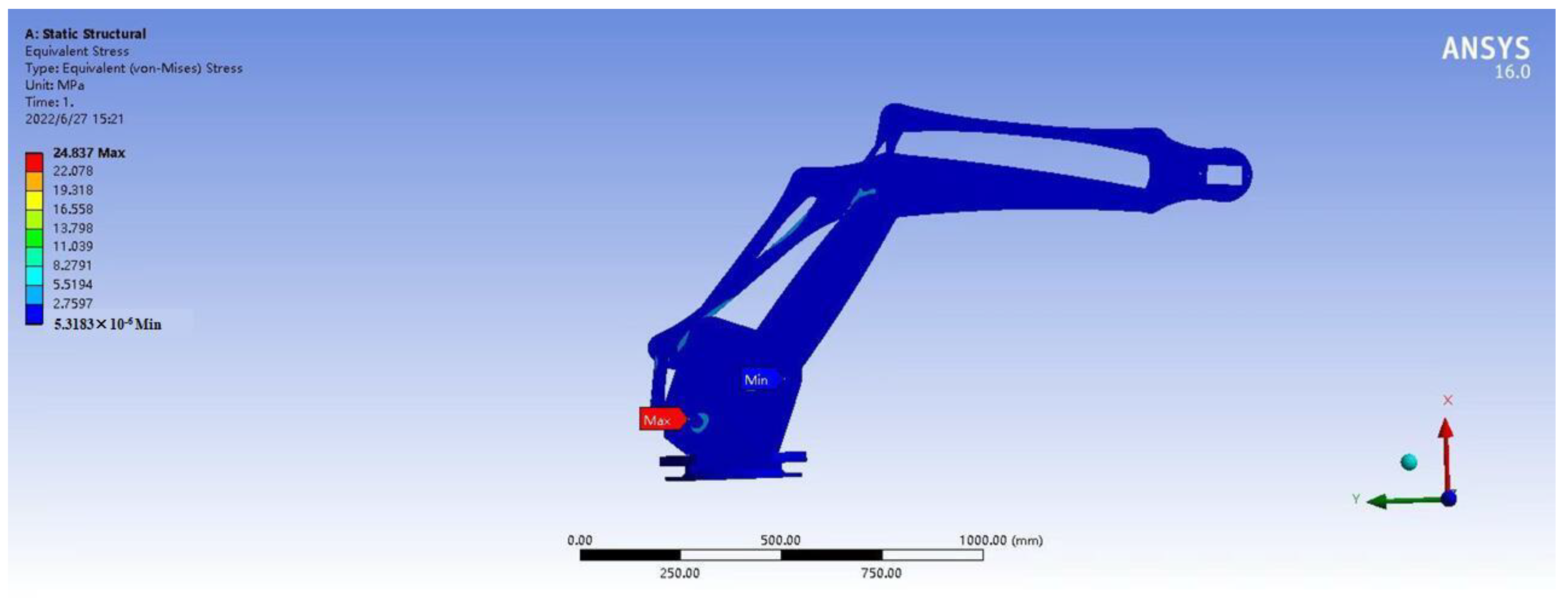
3.6. Structural Stability Analysis

To verify the stability of the cantilever structure, the static analysis of the optimized manipulator’s big arm and forearm have been carried out. The big arm and forearm of the manipulator are made of a thin-walled structure. The base is made of structural steel. The big arm, the forearm, and the joints are all made of aluminum alloy.
An end effector is installed at the end of the manipulator, and the end effector is made of 3D-printed engineering plastics. In the case of holding a large amount of camellia flowers, the total load of the end effector and camellia flower is lower than 100 N.
By applying loads and constraints to the manipulator, the manipulator’s big arm and forearm stress contour in the horizontal direction with a load of 200 N, as shown in Figure 6. The maximum stress of the manipulator occurs at the connection between the big arm and the base. The maximum stress value is 24.837 MPa, which is far lower than the yield limit of the material and meets the design requirements.

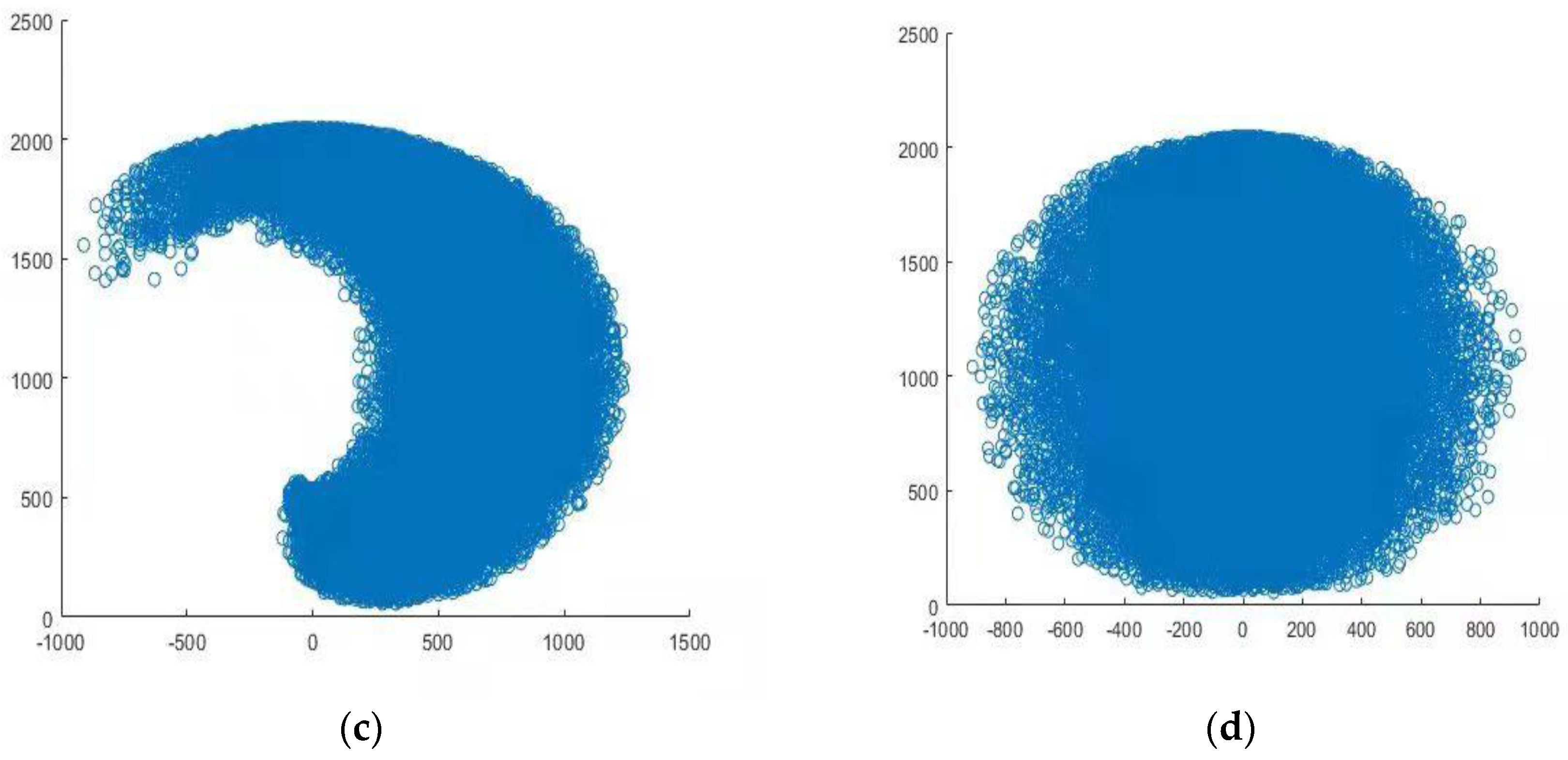
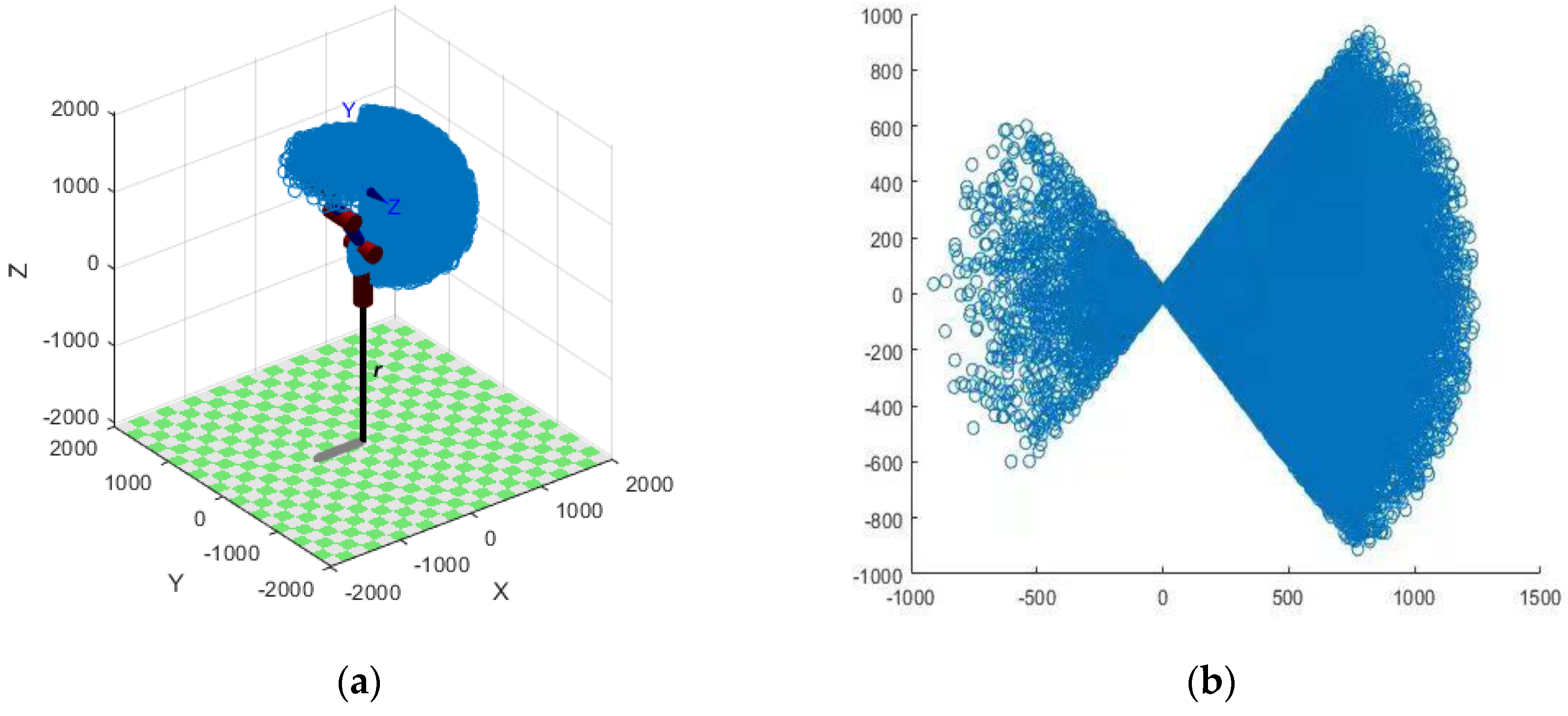
4. Manipulator Workspace Analysis and Simulation

By solving the working space of the camellia-pollen-picking manipulator, the activity range of the camellia-pollen-picking manipulator in three-dimensional space can be simulated. The cloud diagram of the pollen-picking manipulator workspace is shown in Figure 7.
The blue part in Figure 7 is the area that the end of the camellia-pollen-picking manipulator can reach in three-dimensional space. The point–cloud distribution in the space is relatively uniform, which shows that the structure and size of the manipulator are reasonable and provide a theoretical basis for further machining the prototype.
To verify whether the manipulator with the optimized structure parameters can reach the target picking point, a motion-planning experiment was carried out for the reduced-scale model manipulator used in the laboratory from the initial pose of the working state to the target picking point. The experiment was carried out with eight extreme picking points and seven other arbitrary picking points in the target picking area, as shown in Figure 8.
After the reduced-scale model manipulator moves to the specified position, the coordinates of the end position of the manipulator are measured with a portable three-coordinate instrument of the Italian COORD3 brand EOS544 model. The measurement results are shown in Table 2.
As can be seen from Table 2, during the experiments, the reduced-scale model manipulator reached eight extreme picking points and seven other arbitrary picking points in the target picking area for camellia pollen. The reduced-scale model manipulator can move continuously and smoothly, and thus the rationality of the optimal design of the manipulator structure can be verified [25,26,27]. However, during the working process of the manipulator, there is a certain positional deviation from the predetermined position. The maximum errors in the x, y, and z directions are 5.1 mm, 5.7 mm, and 5.1 mm, respectively. The main reason is the position error caused by the structural parameters of each link of the manipulator due to the deviation of the processing and assembly. It can be improved by improving the machine and the assembly accuracy of the parts in the future.

5. Conclusions

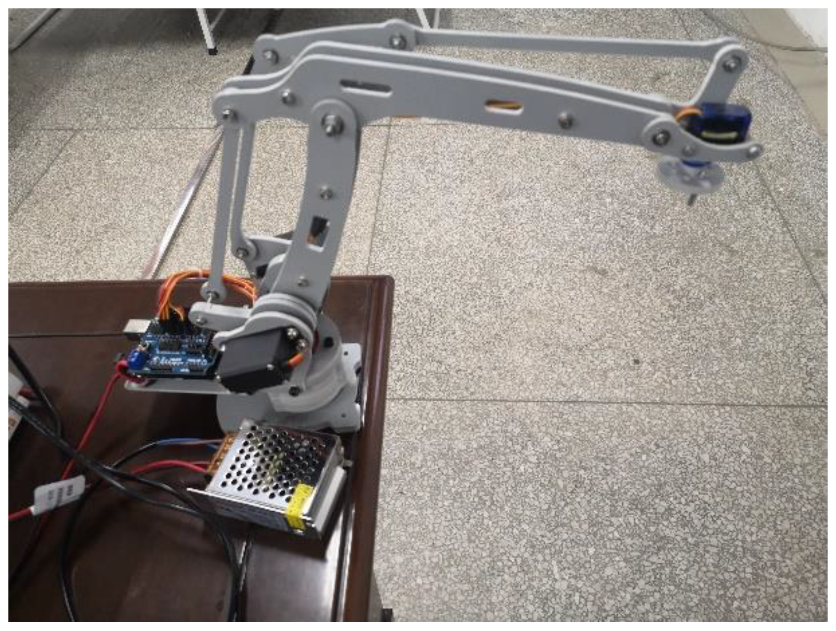
  • Considering the current situation of having no mechanized pollen-picking operation device, a four-degree-of-freedom pollen-picking manipulator has been developed. The manipulator is small, light, and compact. It is verified by a structural stability analysis that the cantilever structure has sufficient strength and bearing capacity.
  • The tree canopy is simplified for pollen picking, and a general optimization method is proposed for the structural parameters of the manipulator for agricultural and forestry operations where the workspace is an arbitrary cube. The MATLAB optimization toolbox is used to optimize the structural parameters, and the optimization results can be used to process the prototype.
  • To verify the rationality of the optimization method, motion-planning experiments were carried out. The results show that the reduced-scale model manipulator can reach eight extreme picking points and seven other arbitrary picking points in the target picking area of camellia pollen. The maximum errors in the x, y, and z directions are 5.1 mm, 5.7 mm, and 5.1 mm, respectively. The manipulator can meet the requirements of the camellia-pollen-picking operation; however, the positioning accuracy can be further improved and lay the foundation for the development of smart agriculture.
  • The camellia-pollen-picking robot proposed in this paper can be further studied in the direction of multi-arm collaborative operation [28,29,30]. If the double-arm collaborative operation can be realized, it can shorten the time of picking a tree and improve the efficiency of pollen picking. If the four-arm collaborative operation can be realized, it may allow the pollen-picking operation of two adjacent camellia trees at the same time which may lead to agricultural robots developing rapidly like industrial robots.

Author Contributions

Conceptualization, L.L. and Q.Z.; methodology, Z.W.; Software, J.L.; validation, X.G.; investigation, Z.W. and X.G.; data curation, J.L.; writing—original draft preparation, Q.Z.; writing—review and editing, L.L. All authors have read and agreed to the published version of the manuscript.

Funding

This research was funded by Scientific Research Fund of Hunan Provincial Education Department (No. 19B596), Natural Science Foundation of Hunan Province (Grant No. 2022JJ40876).

Institutional Review Board Statement

Not applicable.

Informed Consent Statement

Not applicable.

Data Availability Statement

Not applicable.

Acknowledgments

The authors would like to thank the research team members for their contributions to this work.

Conflicts of Interest

The authors declare no conflict of interest.

References

  1. Li, J.K.; Chen, J.; Zhang, Z.H.; Pan, Y. Proteome Analysis of Tea Pollen(Camellia Sinensis ) under Different Storage Conditions. J. Agric. Food Chem. 2008, 56, 7535–7544. [Google Scholar] [CrossRef] [PubMed]
  2. Gao, C.; Yuan, D.; Yang, Y.; Wang, B.; Liu, D.; Zou, F. Pollen Tube Growth and Double Fertilization in Camellia Oleifera. J. Am. Soc. Hortic. Sci. 2015, 140, 12–18. [Google Scholar] [CrossRef] [Green Version]
  3. Zou, F.; Tan, X.; Yuan, D.; Xie, P.; Yuan, J. A Study on Camellia Pollen Number and the Vitality Change under 4 °C Storage. Acta Agric. Univ. Jiangxiensis 2009, 31, 892–895. [Google Scholar]
  4. Zhang, P.; Yang, Y.; Xi, R.C.; Huang, R. Pollen Characteristics of Camellia gauchowensis Chang. For. Res. 2019, 32, 90–96. [Google Scholar]
  5. Guo, Y.; Bao, Y.; He, P.; Wang, H. Design and Experiment of Hand-push Lowbush Blueberry Picking Machine. Trans. Chin. Soc. Agric. Mach. 2012, 28, 40–45. [Google Scholar]
  6. Wang, Y.; Yang, Q.; Bao, G.; Xun, Y.; Zhang, L. Optimization Design and Experiment of Fruit and Vegetable Picking Manipulator. Trans. Chin. Soc. Agric. Mach. 2011, 42, 191–195. [Google Scholar]
  7. Van Henten, E.J.; Van’t Slot, D.A.; Hol, C.W.J.; van Willigenburg, L.G. Optimal Manipulator Design for A Cucumber Harvesting Robot. Comput. Electron. Agric. 2009, 65, 247–257. [Google Scholar] [CrossRef]
  8. Wu, Z.C.; Zhao, Q.; Li, L.J. Study on the design of three-claw linkage type camellia flower picking execution terminal. Chin. J. Constr. Mach. 2022, 20, 69–74, 80. [Google Scholar]
  9. Kondo, N.; Ting, K.C. Robotics for plant production. Artif. Intell. Rev. 1998, 12, 227–243. [Google Scholar] [CrossRef]
  10. Yang, W.L. Design and Analysis of Apple Harvesting Robot’s Manipulator; JiangSu University: Zhenjiang, China, 2009. [Google Scholar]
  11. Wang, L.L. Research on Key Technology of Tomato Havesting Robot; Beijing University of Technology: Beijing, China, 2018. [Google Scholar]
  12. Gao, Y.H. Research on Key Techniques of Strawberry Picking and Optimal Design of Manipulator; Shandong Agricultural University: Tai’an, China, 2021. [Google Scholar]
  13. Mao, L.R.; Wang, S.J.; Xue, T. Optimum design of 7-DOF heavy-duty manipulator based on ADAMS. Manuf. Autom. 2020, 42, 4–7. [Google Scholar]
  14. Luo, J.G.; He, M.Y. Research on the Configurations and Singularity of Serial-parallel Mechanism. Adv. Mater. Res. 2011, 393, 265–268. [Google Scholar] [CrossRef]
  15. Zhang, D.D.; Xu, Y.D.; Hou, Z.W.; Yao, J.; Zhao, Y. Optimal Design and Kinematic Analysis of 5-DOF Hybrid Serial-parallel Manipulator. Trans. Chin. Soc. Agric. Eng. 2016, 32, 69–76. [Google Scholar]
  16. Carp-Ciocardia, D.C. Dynamic Analysis of Clavel’s Delta Parallel Robot. In Proceedings of the 2003 IEEE International Conference on Robotics and Automation 2003, Taipei, Taiwan, 14–19 September 2003. [Google Scholar]
  17. Wang, Y.; Zhang, M.; Liu, B.; Liu, S.; He, Y.; Xu, H. Design and Experiment of Clamping Mechanism About End-effector for Citrus Harvesting Robot. J. Agric. Sci. Technol. 2019, 21, 61–69. [Google Scholar]
  18. Wang, Y.; Fu, S.; Zhang, Z.; Ma, J.; Xu, H. Design and Experimentation on End-effector of Citrus Picking Robot. J. Agric. Sci. Technol. 2018, 20, 69–77. [Google Scholar]
  19. Li, J.; Karkee, M.; Zhang, Q.; Xiao, K.; Feng, T. Characterizing Apple Picking Patterns for Robotic Harvesting. Comput. Electron. Agric. 2016, 127, 633–640. [Google Scholar] [CrossRef] [Green Version]
  20. Qin, X.; Shi, M.; Hou, Z.; Li, S.; Li, H.; Liu, H. Analysis of 3-DOF Cutting Stability of Titanium Alloy Helical Milling Based on PKM and Machining Quality Optimization. Machine 2022, 10, 404. [Google Scholar] [CrossRef]
  21. Law, M.; Ihlenfeldt, S.; Wabner, M.; Altintas, Y.; Neugebauer, R. Position-dependent Dynamics and Stability of Serial-parallel Kinematic Machines. CIRP Ann. 2013, 62, 375–378. [Google Scholar] [CrossRef]
  22. Song, Y.; Lian, B.; Sun, T.; Dong, G.; Qi, Y.; Gao, H. A Novel Five-Degree-of-Freedom Parallel Manipulator and Its Kinematic Optimization. J. Mech. Robot. 2014, 6, 041008. [Google Scholar] [CrossRef]
  23. Liu, J.Z.; Li, P.P.; Li, Z.G. Hardware Design of the End-effector for Tomato-harvesting Robot. Trans. Chin. Soc. Agric. Mach. 2008, 39, 109–112. [Google Scholar]
  24. Gasparetto, A.; Zanotto, V. A New Method for Smooth Trajectory Planning of Robot Manipulators. Mech. Mach. Theory 2007, 42, 455–471. [Google Scholar] [CrossRef]
  25. Yao, L.J.; Ding, W.M.; Chen, Y.L.; Zhao, S. Obstacle Avoidance Path Planning of Eggplant Harvesting Robot Manipulator. Trans. Chin. Soc. Agric. Mach. 2008, 39, 94–97. [Google Scholar]
  26. Zhang, D.S.; Xu, Y.D.; Yao, J.T.; Hu, B.; Zhao, Y. Kinematics, dynamics and stiffness analysis of a novel 3-DOF Kinematically/Actuation Redundant Planar Parallel Mechanism. Mech. Mach. Theory 2017, 116, 203–219. [Google Scholar] [CrossRef]
  27. Chai, S.P.; Yao, L.J.; Xu, L.J.; Chen, Q.; Xu, T.; Yang, Y. Research on Greenhouse Agricultural Machinery Path Tracking Based on Dynamic Look Ahead Distance Pure pursuit Model. J. Chin. Agric. Mech. 2021, 42, 58. [Google Scholar]
  28. Zhong, J.W. Vision Fusion Based Trajectory Planning and Control of Dual-Arm Collaborative Robot; Hangzhou Dianzi University: Hangzhou, China, 2021. [Google Scholar]
  29. Buhl, J.F.; Grønhøj, R.; Jørgensen, J.K.; Mateus, G.; Pinto, D.; Sørensen, J.K.; Bøgh, S.; Chrysostomou, D. A Dual-arm Collaborative Robot System for The Smart Factories of The Future. Procedia Manuf. 2019, 38, 333–340. [Google Scholar] [CrossRef]
  30. Quan, L.Z.; Zhang, D.D.; Zha, S.H.; Xi, D.; Wang, H. Kinematics Analysis and Experiment of Multifunctional Agricultural Robot in Greenhouse with Three Arms. Trans. Chin. Soc. Agric. Eng. 2015, 31, 32–38. [Google Scholar]
Figure 1. View of the pollen-picking manipulator.
Applsci 12 08011 g001
Figure 2. Three-dimensional model of the pollen-picking robot.
Applsci 12 08011 g002
Figure 3. View of the pollen-picking robot and the target picking area.
Applsci 12 08011 g003
Figure 4. View of the simplified working space.
Applsci 12 08011 g004
Figure 5. Reachable workspace of main links.
Applsci 12 08011 g005
Figure 6. Manipulator’s big arm and forearm stress contour.
Applsci 12 08011 g006
Figure 7. Cloud diagram of the pollen-picking manipulator workspace. (a) 3D−space cloud diagram: (b) X/Y−plane projection; (c) X/Z−plane projection; (d) Y/Z−plane projection.
Applsci 12 08011 g007aApplsci 12 08011 g007b
Figure 8. Motion-planning experiment of pollen-picking manipulator.
Applsci 12 08011 g008
Table 1. Pollen-picking manipulator parameters.
ParametersSymbolsValues
Multi-functional power platform lengthL1354 mm
Multi-functional power platform widthB900 mm
Multi-functional power platform heightH816 mm
The height of the bench for installing the manipulatorH1500 mm
The big arm length of the manipulator l 1 ?
Forearm length of the manipulator l 2 ?
End effector length of the manipulator l 3 318 mm
The big arm rotation angle φ 1 [−50°, 50°]
The big arm pitch angle θ 1 [60°, 120°]
Forearm pitch angle θ 2 [θ2min, 180°]
End effector pitch angle θ 3 360° − (θ1 + θ2)
Table 2. Measurement results of the end position of the pollen-picking manipulator.
NumberTheoretical ValueMeasured ValueAbsolute Value of Error
PxPyPzPxPyPzExEyEz
1950725340954.4730.1344.84.45.14.8
29507251700947.3721.51695.42.73.54.6
3950−7201700946.2−724.31704..33.84.34.3
4950−720340945.8−723.8344.64.23.84.6
5320725340316.2722.6336.53.82.43.5
63207251700317.5729.41705.12.54.45.1
7320−7201700322.8−717.41695.12.82.64.9
8320−720340325.1−724.9343.55.14.93.5
9400−600400403.5−604.6403.53.54.63.5
10480−300650483.7−294.3647.13.75.72.9
11640−200900636.8−202.9895.44.62.94.6
126502401040654.1243.51044.94.12.94.9
136803001300678.1302.51304.21.92.54.2
147003401530704.6344.21526.33.54.23.7
157506001650746.4604.61646.53.64.63.5
Publisher’s Note: MDPI stays neutral with regard to jurisdictional claims in published maps and institutional affiliations.

