Abstract
In this paper, the design of an ultra-wideband polarizer based on a metasurface with high-performance is reported and demonstrated. The polarizer is composed of a dielectric substrate with double semicircular gap patches and a metal film. Multiple strong resonance points enable the design to convert the incident linearly polarized waves into cross-polarized waves in the 14.8–28.0 GHz range, with a fractional bandwidth of 61.7% and a corresponding polarization conversion rate (PCR) above 95%. Further simulated results show that the PCR remains above 87% in the 14.37–24.75 GHz range when the incident angle of the electromagnetic (EM) waves is between 0–30°, and the physical mechanism is explained by the surface current distribution. In addition, the gradient metasurface is designed according to the Pancharatnam–Berry phase principle to achieve anomalous reflection, and the 1-bit metasurface is coded to reduce the Radar Cross Section (RCS). The EM waves reach an anomalous reflection of −23° at 15 GHz normal incidence, and the RCS is reduced by 10 dB in the range of 15.3–28.0 GHz. These findings have potential application value in stealth and antenna design.
1. Introduction
In the past few decades, the development of metamaterials (MMs) [1,2,3] has shifted from three-dimensional (3D) structures to two-dimensional (2D) planar structures. Com-pared with 3D MMs, metasurfaces [4,5,6,7] have attracted extensive attention because of their advantages of low loss and low profile. In recent years, many technologies have been developed, such as metastructures [8], near-zero-index materials [9], plasmonics [10], nanoparticles [11], graphene [12] and multi-functional structures [13]. Due to their powerful ability to manipulate EM waves, the metasurface has been applied in many devices, including absorbers [14,15], polarizers [16,17], holography [18], antennas [19], beam generator, filters and sensors [20].
A gradient metasurface was first proposed by Yu et al. to prove the generalized Snell’s law [21]. At present, the general method to achieve a phase gradient is to rotate the direction or change the geometry of the structure. In particular, the Pancharatnam–Berry phase in space will be generated under the incident circularly polarized waves, and many peculiar physical phenomena have been realized. For example, anomalous reflection/refraction [22,23,24,25], beam focusing [26,27] and vortex beams [28,29,30].
Furthermore, with the development of radio frequency and microwave technologies, effective RCS reduction is one of the most promising methods in stealth technology. The traditional methods to achieve RCS reduction are radar absorption MMs and phase interference cancellation techniques [31]. However, problems such as EM absorption energy being easily captured by the infrared detector and the very narrow bandwidth limit these two methods [32]. Polarization converters and multilayer structures [33] have been proposed to expand the bandwidth, but these methods complicate the structural design and deteriorate the antenna performance. In recent years, the concept of a coding metasurface was proposed by Cui et al. They designed the “0” and “π” phase cells to simulate a digitally encoded “0” and “1” and combined these with optimization algorithms to accurately control the EM waves. This approach also provides possibilities for the design of RCS reduction. According to this principle, RCS reduction from 1-bit [34] to multi-bit [35] encoded metasurfaces has been demonstrated. A multi-static radar stealth metasurface based on a particle swarm optimization algorithm was proposed by Su et al. [36]. However, design challenges remain in achieving excellent RCS reduction characteristics for greater bandwidth and ultra-thin structures.
In this paper, we report the design of an ultra-thin and ultra-wideband linear polarizer. The simulated results show that the conversion from linearly polarized waves to cross-polarized waves is realized in the 14.8–28.0 GHz range, and the corresponding PCR is more than 95%. In addition, a gradient metasurface is simulated at 15 GHz, achieving an anomalous reflection of −23°. The coded metasurface is composed of anisotropic units derived by rotating the double semicircular gap patch structure by 90° to meet the phase difference requirements. The meta-unit is composed of 4 × 4 identical meta-atom classes. The simulated results show that a 10 dB RCS reduction can be attained in the 15.3–28.0 GHz range. The RCS reduction is more significant than in the checkerboard pattern.
2. Structural Design and Principles
Herein, we propose an ultra-thin and ultra-wideband linear polarizer, and the unit cell is shown in Figure 1a. It consists of three layers. The top layer comprises the double semicircular gap patches. The intermediate layer is FR-4 with a dielectric constant of 4.3 and loss tangent of 0.025. The bottom layer is copper with a conductivity of 5.8 × 10⁷ S/m and a thickness of 0.035 mm. The detailed structural parameters are as follows: p = 6 mm, a = b = c = 1 mm and t = 1.5 mm.
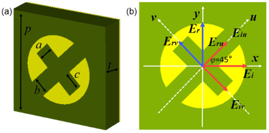
Figure 1.
(a) Schematic diagram of unit structure parameters. (b) Diagram of the working principle of polarization conversion.
In order to clearly understand the principle of polarization conversion, we used CST Microwave Studio for the simulation analysis. The principle of the polarization converter is shown in Figure 1b. The u–v axis is obtained by rotating the x–y axis 45° counterclockwise. Since the structures have symmetry along the u–v axis, they have the same polarization conversion capability regardless of whether the electric field of the incident wave is in the x or y direction. Assume that the incident and reflected electric fields are along the x and y axes, respectively. Eiv (Eiu) and Erv (Eru) represent the electric field components of the incident and reflected waves on the v (u) axis, respectively. Because of the anisotropy of the structure, if ruu = rvv, Δφ = φuu − φvv = π, then the electric field along the x axis will be reversed, and the synthetic reflection of Erv and Eru will propagate along the y axis. Herein, ruu(rvv) and φuu(φvv) represent the amplitude and phase along the u, v axes, respectively. The incident x-polarized wave is decomposed to the u, v axes, and the simulated amplitude and phase difference are shown in Figure 2. Obviously, the amplitudes of ruu and rvv are almost coincident and the phase difference is about 180° ± 37° at 14.8–28.0 GHz, and the phase difference at 15.45 GHz, 20.82 GHz and 26.94 GHz is equal to 180°, which means that it has an efficient conversion capability in the ultra-wideband range.
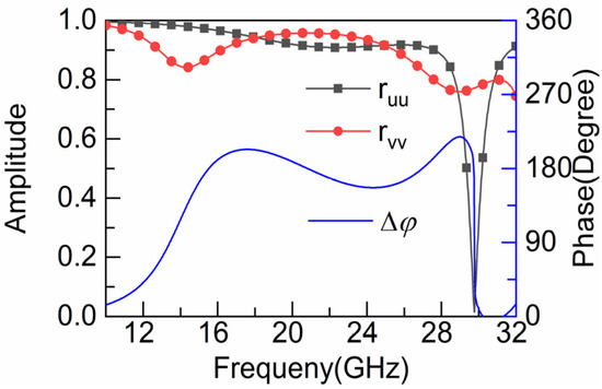
Figure 2.
The amplitude and phase difference of u and v axes.
We also give the equivalent circuit models based on transmission line theory to analyze the behavior of the proposed structure, as depicted in Figure 3. The top metal structure can be equivalent to R1, L1 and C1 in series. The spacing between the double semicircular gap patches exhibits capacitance and can be equated to Cd. The length of h transmission line represents the dielectric substrate. Z0 and Z1 are the equivalent characteristic impedance of the free space and dielectric substrate, respectively. The equivalent admittance and impedance of the top structures are as follows:
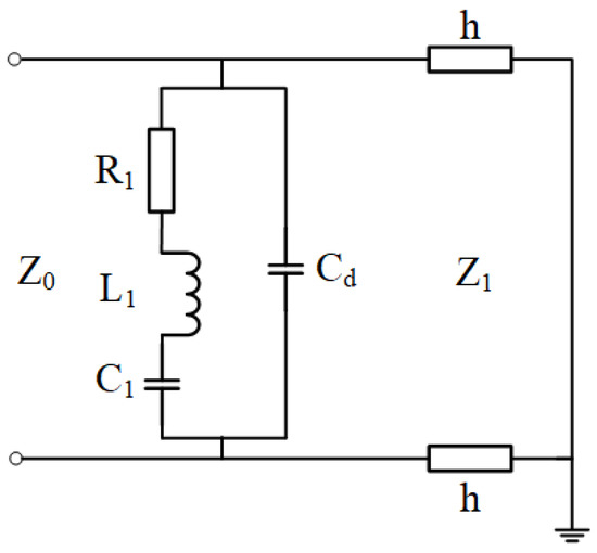
Figure 3.
The equivalent circuit model.
The equivalent impedance of the dielectric substrate is as follows:
β, h are the phase constant and thickness of the dielectric substrate, respectively.
The equivalent impedance of the polarizer is expressed as follows:
The equivalent impedance of the polarizer can be determined by tuning the structure period, thickness, double semicircular gap patch parameters, etc.
3. Simulation, Experiment and Discussion
In order to investigate the polarization conversion characteristics of the metasurface, we define rxx = |Exr|/|Eyi| and ryx = |Eyr|/|Exi| as the reflection amplitudes of the co-polarization and cross-polarization of x-polarized waves, respectively. Meanwhile, PCR = |ryx|2/(|rxx|2 + |ryx|2) is defined to describe the polarization conversion efficiency. Figure 4a,b shows the corresponding simulated results. The summarized performances of the polarizer are presented in Table 1. Moreover, the PCR is above 87% at 14.37–24.75 GHz when the oblique incidence angle is 0–30°, indicating that the vertically incident x-polarized waves are effectively reflected as y-polarized waves.
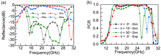
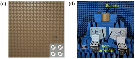
Figure 4.
Simulated and experimental results for (a) reflectance, and (b) PCR, and images of (c) sample and (d) test environment and system.

Table 1.
The performances of the polarizer.
To further validate our design, a sample of the reflective polarizer was fabricated and measured in a microwave anechoic chamber. The polarizer contains 40 × 40 cells with a total size of 240 × 240 mm2. Figure 4c presents a partial photograph of the sample. The polarizer was placed on a test bed and normalized using metal plates of the same size. Two horn antennas were connected to the vector network analyzer (R&S ZNB40), one as the transmitting antenna and the other as the receiving antenna, as illustrated in Figure 4d. Figure 4a,b shows the test results. As can be seen from Figure 4a, the co-polarized and cross-polarized reflectivities coincide with the simulated results, but the drops at 20.82 GHz and 26.94 GHz are almost merged, which may be due to fabrication or experimental errors. The corresponding PCR stays above 95% at 15.3–27.5 GHz, proving that the polarizer designed in this paper has an excellent linear polarization capability.
The surface current distributions at the resonance points of 15.45 GHz, 20.82 GHz and 26.94 GHz were monitored to explain the physical mechanism of the polarizer. The direction of the arrow in the figure indicates the direction of the surface current distribution. Figure 5a,b show the current distributions in the upper and lower layers at resonant frequencies of 15.45 GHz and 20.82 GHz, respectively. We can observe that the surface currents in the top and bottom layers are inversely parallel, which means that the magnetic resonance is generated at 15.4 GHz and 20.82 GHz. In contrast, the surface currents shown in Figure 5c are parallel to the same direction, indicating an electrical resonance at 26.94 GHz. Due to the presence of multiple resonances, an efficient linear polarization conversion is achieved in the ultra-wideband range.
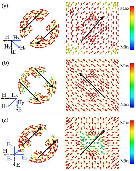
Figure 5.
Surface current distributions at three resonance points: (a) 15.45 GHz, (b) 20.82 GHz and (c) 26.94 GHz.
4. Design and Simulation of Gradient and Code Metasurface
The Pancharatnam–Berry phase theory plays a vital role in manipulating circularly polarized waves. According to the Pancharatnam–Berry phase theory, when the top structure of the polarizer rotates Ψ, the co-polarized reflectance of the circularly polarized waves remains unchanged and the phase difference is 2Ψ, which generates a phase gradient in the polarizer, denoted as follows:
where L = NP, N is the number of sub-units of the polarizer. According to the generalized Snell’s law, the co-polarized reflected waves will be redirected, and the abnormal reflection angle is defined as follows:
where k0 represents the wave vector in free space. If θi = 0, k0 = 2π/λ, the anomalous reflection angle of the EM waves under normal incidence can be calculated theoretically by Equation (5).
Figure 6a,b shows the relationship between the rotation angle Ψ and the reflection magnitude and phase of the polarizer, respectively. It can be noticed that, as the rotation angle increases in steps of 22.5°, the reflection amplitude of the left-handed circularly polarized waves under normal incidence remains stable, and the corresponding reflection phase increases linearly in steps of 45° over a range of 360°, which implies the existence of a phase gradient of the reflected waves.
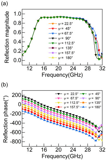
Figure 6.
The relationship between the rotation angle of the top structure of the polarizer and (a) the reflection magnitude and (b) the reflection phase.
In the following, we describe the designed one-dimensional gradient metasurface, as depicted in Figure 7a. The gradient metasurface consists of 8 sub-units, each with the same structural parameters as those shown in Figure 1. In order to study the characteristics of the gradient metasurface, numerical simulations were carried out in CST, and the simulated results are displayed in Figure 7b. In Figure 7b, the anomalous reflection angle decreases with increasing frequency under the incident left-hand circularly polarized waves. The anomalous reflection angles at 15 GHz, 18 GHz, 21 GHz, 24 GHz and 27 GHz are −23.0°, −20.0°, −17.0°, −15.0° and −12.0°, respectively, which are basically consistent with the theoretical calculation results (−24.58°, 20.3°, 17.27°, 15.07°, 13.35°). The simulated results show that the maximum error between the anomalous reflection angle of the gradient metasurface and the theoretical calculation is 1.58°, suggesting that the proposed gradient metasurface has satisfactory performance in anomalous reflection. From the electric field distribution of the reflected waves in Figure 7c,d, we can find that the angle of the reflected waves varies at different frequencies, demonstrating the correctness of the above design.
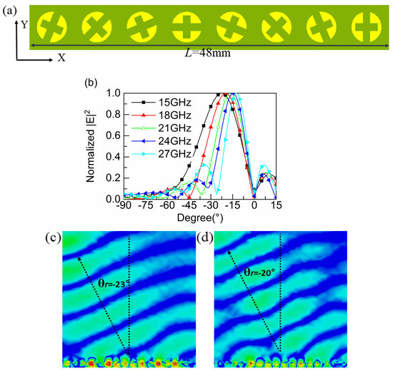
Figure 7.
(a) One dimensional periodic gradient metasurface. (b) Normalized electric field power distribution. (c,d) E-field distribution at different frequencies. (f = 15 GHz, f = 17 GHz).
Moreover, we designed a 1-bit coded metasurface to reduce the RCS. When the reflection phase is 0° and 180°, the metasurface is defined as “0” and “1” in the digitally encoding state. To achieve a 10 dB reduction in RCS, the phase difference between adjacent units should meet 180° ± 37°. On this basis, we built the basic unit and performed the simulation as shown in Figure 8a,b. From Figure 8b, it can be observed that the reflection phase difference between two cells is 180° ± 37° in the range of 15.3–28.0 GHz, which implies that a 10 dB RCS reduction can be realized in this frequency band. We randomly generate a 1-bit coding sequence to achieve a 10 dB RCS reduction. The overall coding layout is shown in Figure 9.
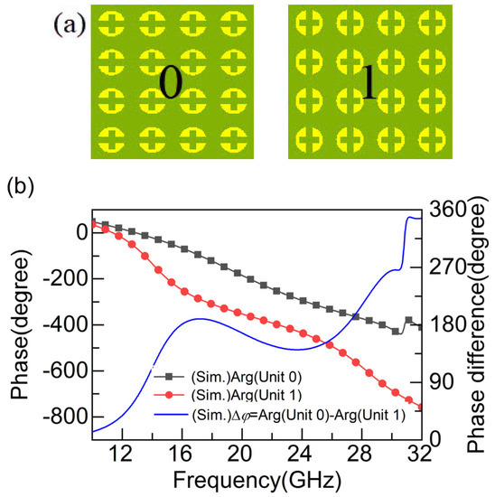
Figure 8.
(a) Coded metasurface elementary particles. (b) Phase.
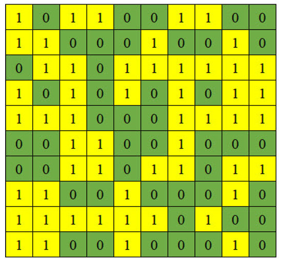
Figure 9.
Coded metasurface layout schematic.
To verify the RCS reduction characteristics of the coded metasurface, a full-wave simulation was performed in CST using the time-domain solution method. As shown in Figure 10, compared with the same size PEC, the monostatic RCS is reduced by more than 10 dB in the range of 15.3–28.0 GHz at normal incidence of both TE and TM EM waves with a relative bandwidth of 65%, which indicates that the encoded metasurface is insensitive to polarization. It is worth noting that the simulated results coincide with the bandwidth in Figure 8b, where the phase difference satisfies 180° ± 37°. In addition, we note that the RCS reduction of the coded metasurface is less than the PEC reduction below 13 GHz because the phase difference of the elementary unit cell does not strictly satisfy 180°, so it cannot be eliminated entirely. This phenomenon can be further improved by adjusting the size. More importantly, the structure proposed in this paper is compared with the conventional checkerboard design, and simulated results show that the encoded metasurface has a more significant RCS reduction.
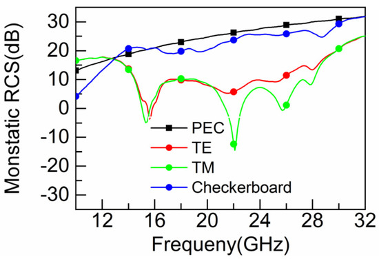
Figure 10.
Comparison of monostatic RCS of coded metasurface and checkerboard under vertical incidence of TE and TM waves.
To more clearly describe the RCS reduction characteristics between the encoded metasurface and PEC, Figure 11 shows the radiation patterns of the E-plane and H-plane at 16.0 GHz, 18.5 GHz and 27.0 GHz. The phase difference at these three frequencies is 180° so they are selected. We can notice that the encoded metasurface at normal incidence is reduced by more than 10 dB compared with the far-field energy of the PEC surface in the range of ±15°, so the designed structure has a good RCS reduction capability.
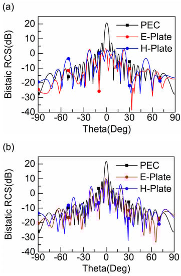
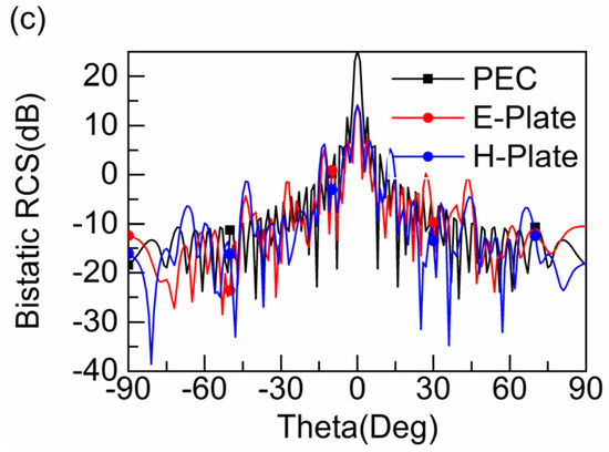
Figure 11.
Two-dimensional scattering patterns at (a) 16.0 GHz, (b) 18.5 GHz and (c) 27.0 GHz.
Coded metamaterials are simple in design structure, easily available and conformal, and can be well integrated with equipment to reduce its RCS while keeping their own performance parameters basically unchanged. Therefore, it has broad application prospects in stealth.
5. Conclusions
To sum up, we have proposed an ultra-broadband linear polarizer. The experimental results show that the conversion from linear polarization to cross-polarization can be achieved in the range of 14.8–28.0 GHz with a relative bandwidth of 61.7% and a corresponding PCR greater than 95%. The working principles and physical mechanisms are analyzed by the electric field decomposition and surface currents. Moreover, based on the Pancharatnam–Berry phase theory, a one-dimensional gradient metasurface and 1-bit coded metasurface are proposed. The simulated results show that −23° anomalous reflection can be realized at 15–27 GHz under normal incident left-handed circularly polarized waves. In addition, the polarizer achieves a 10 dB RCS reduction at 15.3–28.0 GHz with a relative bandwidth of 65%. The EM wave scattering characteristics of the 1-bit coded metasurface are more diverse than those of the PEC and checkerboard structures. The design presented in this paper has potential applications in stealth and antenna design, and other areas.
Author Contributions
Conceptualization, X.L.; methodology, X.L.; software, Y.W.; validation, Y.W.; formal analysis, X.L.; investigation, J.F.; data curation, J.F.; writing—original draft preparation, J.H.; writing—review and editing, X.H.; supervision, X.H. All authors have read and agreed to the published version of the manuscript.
Funding
This work was partially supported by the Project of Science and Technology of Shaanxi (2021JM-395).
Data Availability Statement
All data are contained within the article.
Conflicts of Interest
The authors declare no conflict of interest.
References
- Schurig, D.; Mock, J.J.; Justice, B.J.; Cummer, S.A.; Pendry, J.B.; Starr, A.F.; Smith, D.R. Metamaterial electromagnetic cloak at microwave frequencies. Science 2006, 314, 977–980. [Google Scholar] [CrossRef] [Green Version]
- Smith, D.R.; Padilla, W.J.; VIER, D.C. Composite medium with simultaneously negative permeability and permittivity. Phys. Rev. Lett. 2000, 84, 4184–4187. [Google Scholar] [CrossRef] [Green Version]
- Plum, E.; Zhou, J.; Dong, J.; Fedotov, V.A.; Koschny, T.; Soukoulis, C.M.; Zheludev, N.I. Metamaterial with negative index due to chirality. Phys. Rev. B 2009, 79, 035407. [Google Scholar] [CrossRef] [Green Version]
- Yu, N.; Capasso, F. Flat optics with designer metasurfaces. Nat. Mater. 2014, 13, 139–150. [Google Scholar] [CrossRef]
- Monticone, F.; Estakhri, N.M.; Alù, A. Full control of nanoscale optical transmission with a composite metascreen. Phys. Rev. Lett. 2013, 110, 203903. [Google Scholar] [CrossRef]
- Li, P.C.; Zhao, Y.; Alú, A.; Yu, E.T. Experimental realization and modeling of a subwavelength frequency-selective plasmonic metasurface. Appl. Phys. Lett. 2011, 99, 2011–2014. [Google Scholar] [CrossRef] [Green Version]
- Sun, S.; He, Q.; Xiao, S.; Xu, Q.; Li, X.; Zhou, L. Gradient-index meta-surfaces as a bridge linking propagating waves and surface waves. Nat. Mater. 2012, 11, 426–431. [Google Scholar] [CrossRef]
- Estakhri, N.M.; Edwards, B.; Engheta, N. Inverse-designed metastructures that solve equations. Science 2019, 363, 6433. [Google Scholar]
- La Spada, L.; Vegni, L. Near-zero-index wires. Opt. Express 2017, 25, 23699–23708. [Google Scholar] [CrossRef] [PubMed] [Green Version]
- Greybush, N.J.; Pacheco-Penã, V.; Engheta, N.; Murray, C.B.; Kagan, C.R. Plasmonic optical and chiroptical response of self-assembled Au nanorod equilateral trimers. ACS Nano 2019, 13, 1617–1624. [Google Scholar] [CrossRef]
- Lalegani, Z.; Seyyed Ebrahimi, S.A.; Hamawandi, B.; La Spada, L.; Batili, H.; Toprak, M.S. Targeted dielectric coating of silver nanoparticles with silica to manipulate optical properties for metasurface applications. Mater. Chem. Phys. 2022, 287, 126250. [Google Scholar] [CrossRef]
- Akbari, M.; Shahbazzadeh, M.J.; La Spada, L.; Khajehzadeh, A. The graphene field effect transistor modeling based on an optimized ambipolar virtual source model for DNA detection. Appl. Sci. 2021, 11, 8114. [Google Scholar] [CrossRef]
- Donnelly, E.; Spada, L. La Electromagnetic and thermal nanostructures: From waves to circuits. Eng. Res. Express 2020, 2, 015045. [Google Scholar] [CrossRef]
- Landy, N.I.; Sajuyigbe, S.; Mock, J.J.; Smith, D.R.; Padilla, W.J. Perfect metamaterial absorber. Phys. Rev. Lett. 2008, 100, 207402. [Google Scholar] [CrossRef] [PubMed]
- Stephen, L.; Yogesh, N.; Subramanian, V. Realization of bidirectional, bandwidth-enhanced metamaterial absorber for microwave applications. Sci. Rep. 2019, 9, 10058. [Google Scholar] [CrossRef]
- Wang, H.B.; Cheng, Y.J.; Member, S.; Chen, Z.N. Wideband and wide-angle single-layered-substrate linear-to-circular polarization metasurface converter. IEEE Trans. Antennas Propag. 2019, 68, 1186–1191. [Google Scholar] [CrossRef]
- Gao, X.; Han, X.; Cao, W.P.; Li, H.O.; Ma, H.F.; Cui, T.J. Ultrawideband and high-efficiency linear polarization converter based on double v-shaped metasurface. IEEE Trans. Antennas Propag. 2015, 63, 3522–3530. [Google Scholar] [CrossRef]
- Chen, K.; Feng, Y.; Monticone, F.; Zhao, J.; Zhu, B.; Jiang, T.; Zhang, L.; Kim, Y.; Ding, X.; Zhang, S.; et al. A reconfigurable active Huygens’ metalens. Adv. Mater. 2017, 29, 1606422. [Google Scholar] [CrossRef] [Green Version]
- Fan, Y.; Wang, J.; Li, Y.; Zhang, J.; Han, Y.; Qu, S. Low-RCS and high-gain circularly polarized metasurface. IEEE Trans. Antennas Propag. 2019, 67, 7197–7203. [Google Scholar] [CrossRef]
- Hao, W.; Deng, M.; Chen, S.; Chen, L. High-efficiency generation of airy beams with huygens’ metasurface. Phys. Rev. Appl. 2019, 11, 054012. [Google Scholar] [CrossRef]
- Yu, N.; Genevet, P.; Kats, M.A.; Aieta, F.; Capasso, F.; Gaburro, Z.; Capasso, F.; Gaburro, Z. Light propagation with phase discontinuities: Generalized laws of reflection and refraction. Science 2011, 334, 333–337. [Google Scholar] [CrossRef] [Green Version]
- Chen, Z.; Deng, H.; Xiong, Q.; Liu, C. Phase gradient metasurface with broadband anomalous reflection based on cross-shaped units. Appl. Phys. A 2018, 124, 281. [Google Scholar] [CrossRef]
- Suzuki, T.; Kondoh, S. Negative refractive index metasurface in the 2.0-THz band. Opt. Mater. Express 2018, 8, 1916–1925. [Google Scholar] [CrossRef]
- Kazemi, H.; Albooyeh, M.; Capolino, F. Simultaneous perfect bending and polarization rotation of electromagnetic wavefront using chiral gradient metasurfaces. Phys. Rev. Appl. 2020, 13, 024078. [Google Scholar] [CrossRef] [Green Version]
- Zhang, J.; Yang, L.; Li, L.; Zhang, T.; Li, H.; Wang, Q.; Hao, Y.; Lei, M.; Bi, K. High-efficiency polarization conversion phase gradient metasurface for wideband anomalous reflection. J. Appl. Phys. 2017, 122, 014501. [Google Scholar] [CrossRef]
- Ma, W.; Jia, D.; Yu, X.; Feng, Y.; Zhao, Y. Reflective gradient metasurfaces for polarization-independent light focusing at normal or oblique incidence. Appl. Phys. Lett. 2016, 108, 071111. [Google Scholar] [CrossRef]
- Yue, H.; Chen, L.; Yang, Y.; He, L.; Shi, X. Design and implementation of a dual frequency and bidirectional phase gradient metasurface for beam convergence. IEEE Antennas Wirel. Propag. Lett. 2019, 18, 54–58. [Google Scholar] [CrossRef]
- Xu, B.; Wu, C.; Wei, Z.; Fan, Y.; Li, H. Generating an orbital-angular-momentum beam with a metasurface of gradient reflective phase. Opt. Mater. Express 2016, 6, 3940. [Google Scholar] [CrossRef]
- Tang, S.; Cai, T.; Liang, J.-G.; Xiao, Y.; Zhang, C.-W.; Zhang, Q.; Hu, Z.; Jiang, T. High-efficiency transparent vortex beam generator based on ultrathin Pancharatnam–Berry metasurfaces. Opt. Express 2019, 27, 1816. [Google Scholar] [CrossRef]
- Xu, H.X.; Liu, H.; Ling, X.; Sun, Y.; Yuan, F. Broadband vortex beam generation using multimode Pancharatnam-Berry metasurface. IEEE Trans. Antennas Propag. 2017, 65, 7378–7382. [Google Scholar] [CrossRef]
- Li, Y.; Zhang, J.; Qu, S.; Wang, J.; Chen, H.; Xu, Z.; Zhang, A. Wideband radar cross section reduction using two-dimensional phase gradient metasurfaces. Appl. Phys. Lett. 2014, 104, 1473–1476. [Google Scholar] [CrossRef]
- Yoo, M.; Kim, H.K.; Lim, S. Angular- and polarization-insensitive metamaterial absorber using subwavelength unit cell in multilayer technology. IEEE Antennas Wirel. Propag. Lett. 2016, 15, 414–417. [Google Scholar] [CrossRef]
- Liu, S.; Chen, H.; Cui, T.J. A broadband terahertz absorber using multi-layer stacked bars. Appl. Phys. Lett. 2015, 106, 151601. [Google Scholar] [CrossRef]
- Fu, C.; Han, L.; Liu, C.; Lu, X.; Sun, Z. Reflection-type 1-Bit coding metasurface for RCS reduction combined diffusion and reflection. J. Phys. D Appl. Phys. 2020, 53, 124575. [Google Scholar] [CrossRef]
- Kong, X.; Wang, Q.; Jiang, S.; Kong, L.; Yuan, J.; Yan, X.; Wang, X.; Zhao, X. A metasurface composed of 3-bit coding linear polarization conversion elements and Its application to RCS reduction of patch antenna. Sci. Rep. 2020, 10, 17843. [Google Scholar] [CrossRef]
- Su, J.; Lu, Y.; Zheng, Z.; Li, Z.; Yang, Y.; Che, Y.; Qi, K. Fast analysis and optimal design of metasurface for wideband monostatic and multistatic radar stealth. J. Appl. Phys. 2016, 120, 205107. [Google Scholar] [CrossRef]
Publisher’s Note: MDPI stays neutral with regard to jurisdictional claims in published maps and institutional affiliations. |
© 2022 by the authors. Licensee MDPI, Basel, Switzerland. This article is an open access article distributed under the terms and conditions of the Creative Commons Attribution (CC BY) license (https://creativecommons.org/licenses/by/4.0/).