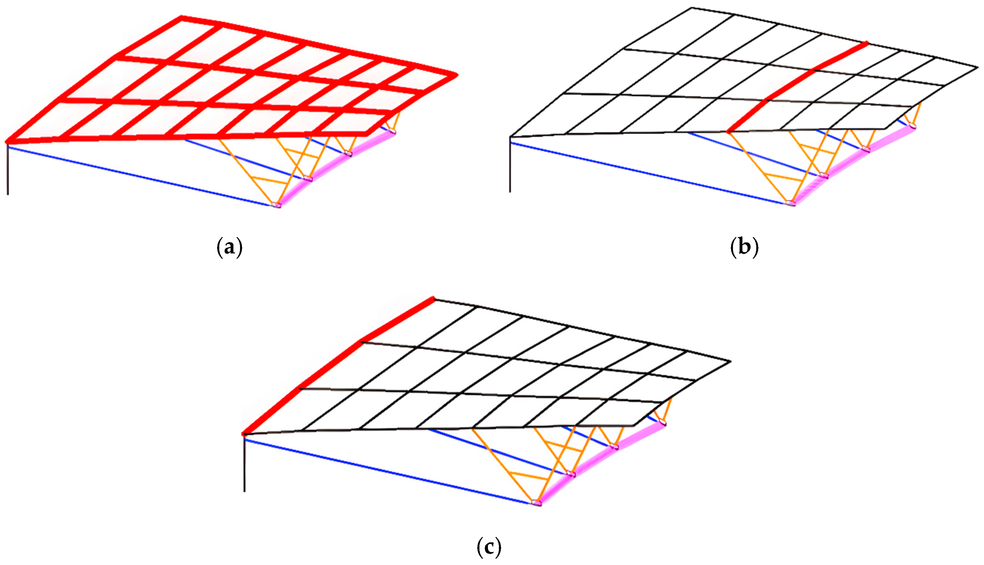
Figure 1.
Types of cable supported grid structures: (a) upper reticulated shell, (b) outer compression ring, and (c) inner compression ring balancing radial cable force.
Figure 1.
Types of cable supported grid structures: (a) upper reticulated shell, (b) outer compression ring, and (c) inner compression ring balancing radial cable force.
Figure 2.
Integral 3D axonometric drawing.
Figure 2.
Integral 3D axonometric drawing.
Figure 3.
Detailed 3D axonometric drawings: (a) upper main steel members (radial main beams, braces, etc.), (b) roof purlins, (c) outer compression ring, (d) cable net system (radial cables + tension rings), (e) structural columns and crossing braces between columns, (f) partial overall structure.
Figure 3.
Detailed 3D axonometric drawings: (a) upper main steel members (radial main beams, braces, etc.), (b) roof purlins, (c) outer compression ring, (d) cable net system (radial cables + tension rings), (e) structural columns and crossing braces between columns, (f) partial overall structure.
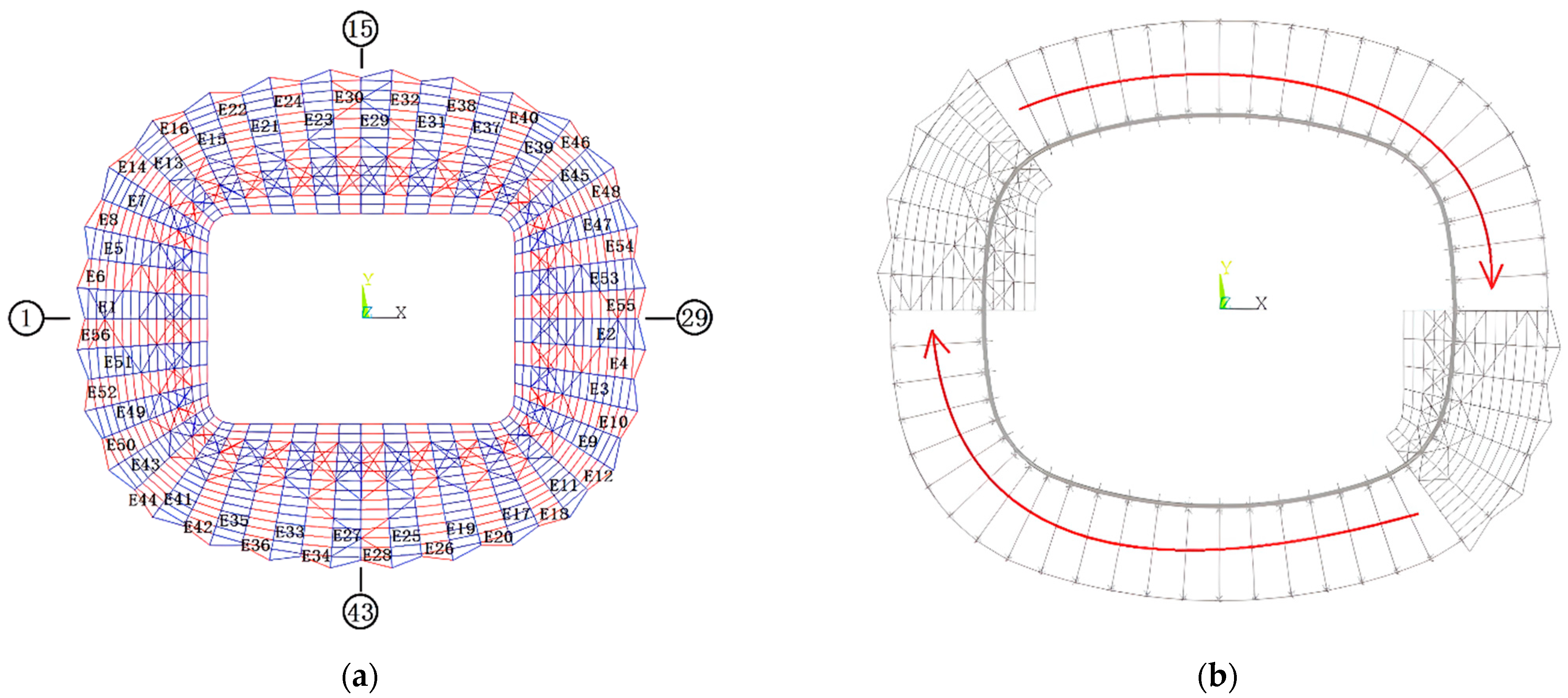
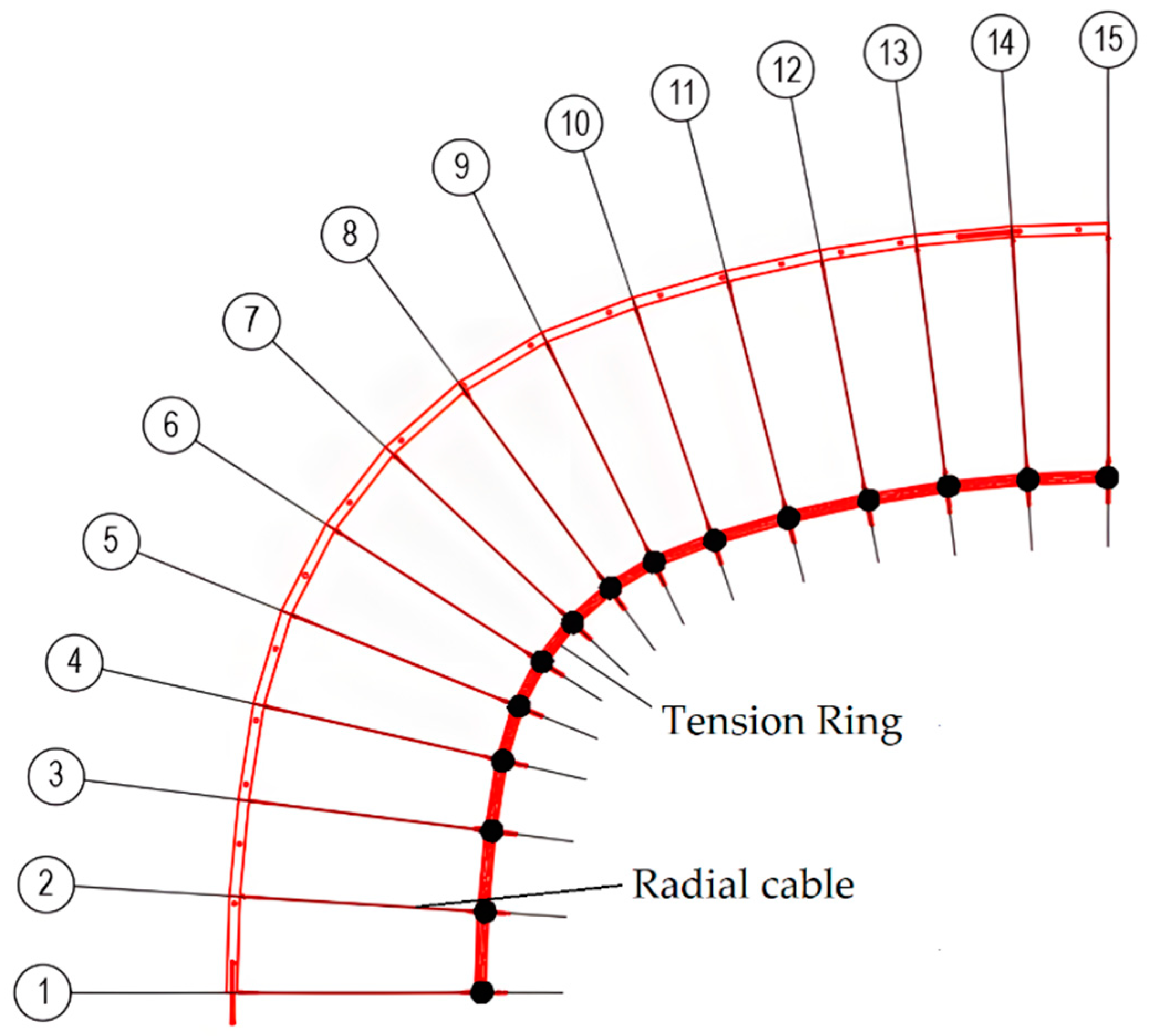
Figure 4.
Layout of cable net.
Figure 4.
Layout of cable net.
Figure 5.
Prestress flow control process.
Figure 5.
Prestress flow control process.
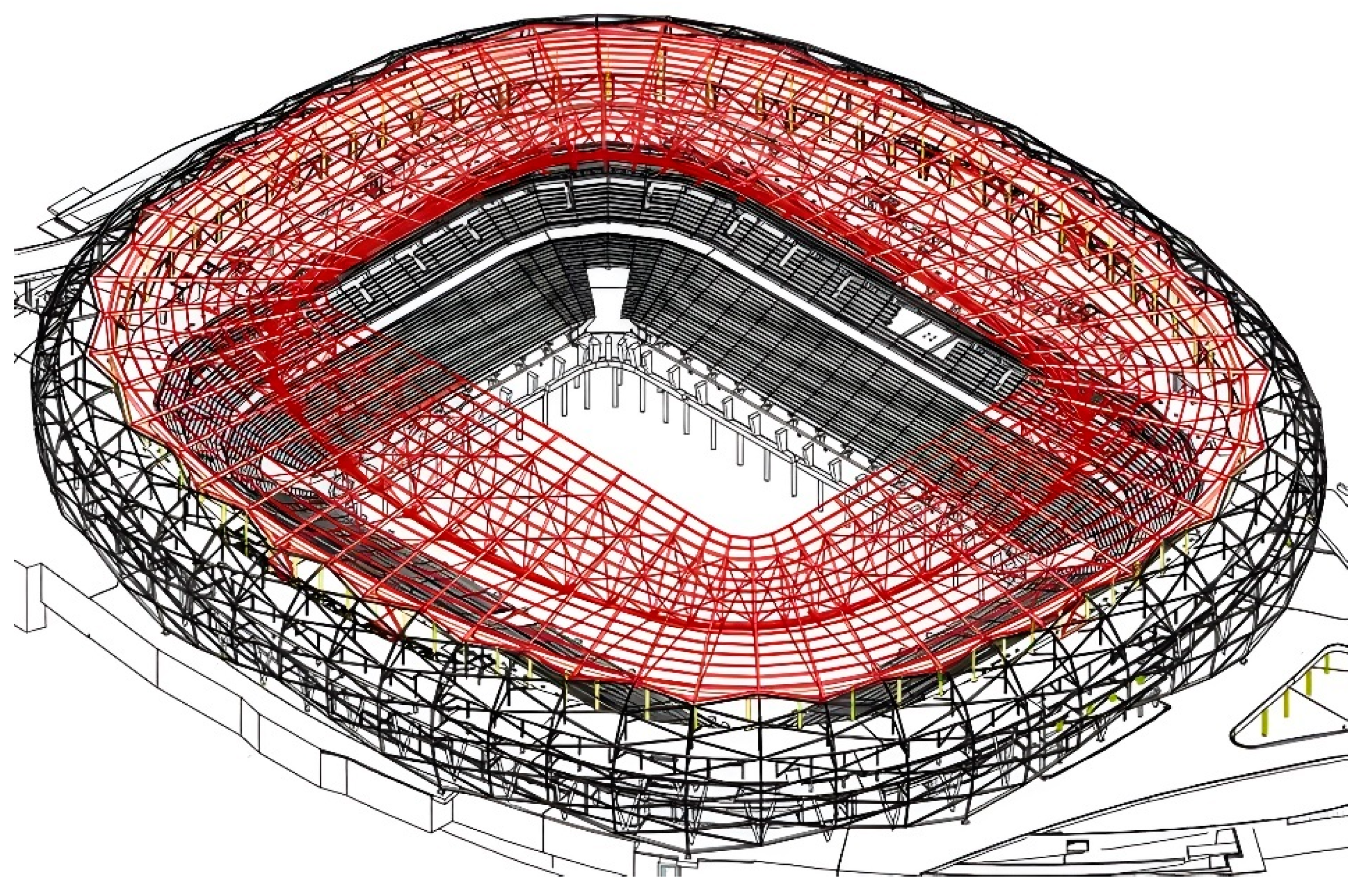
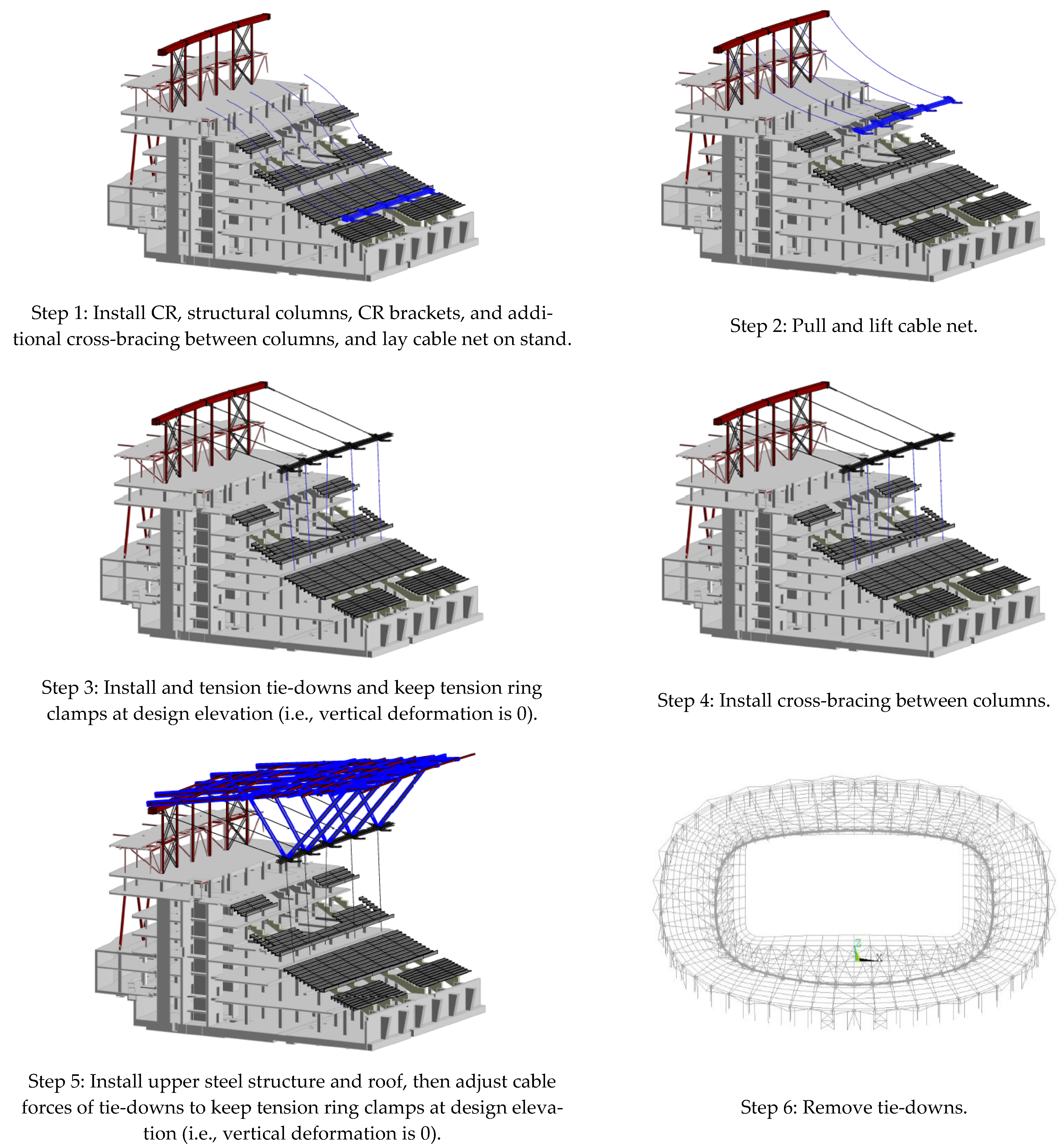
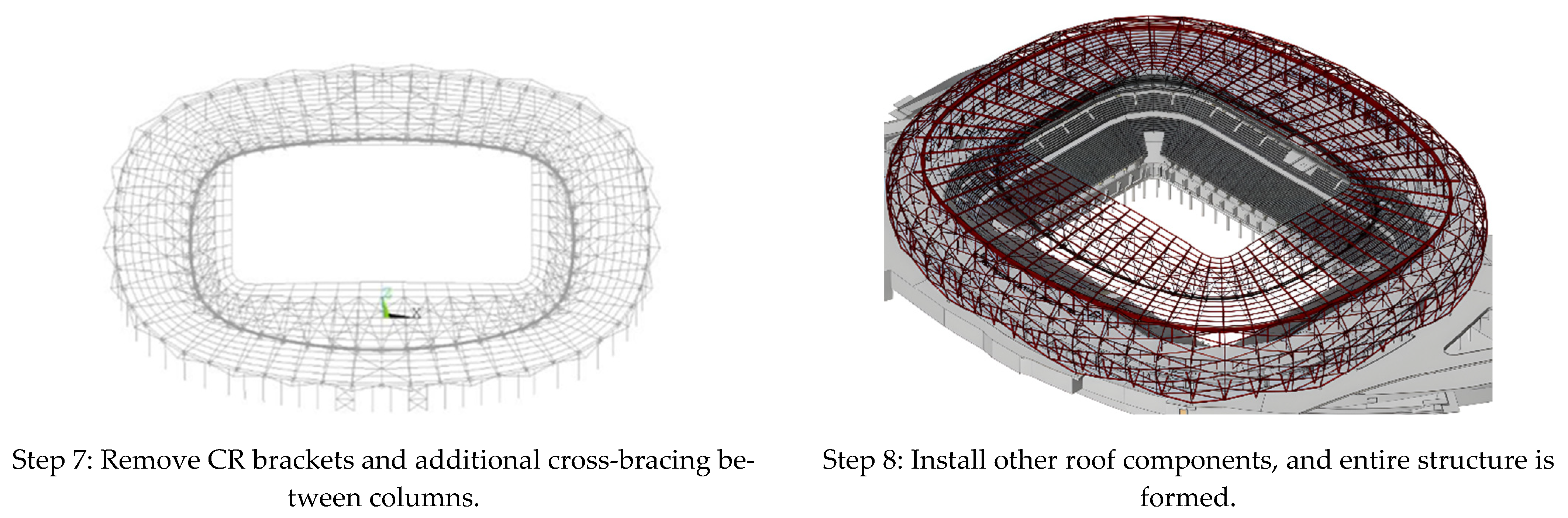
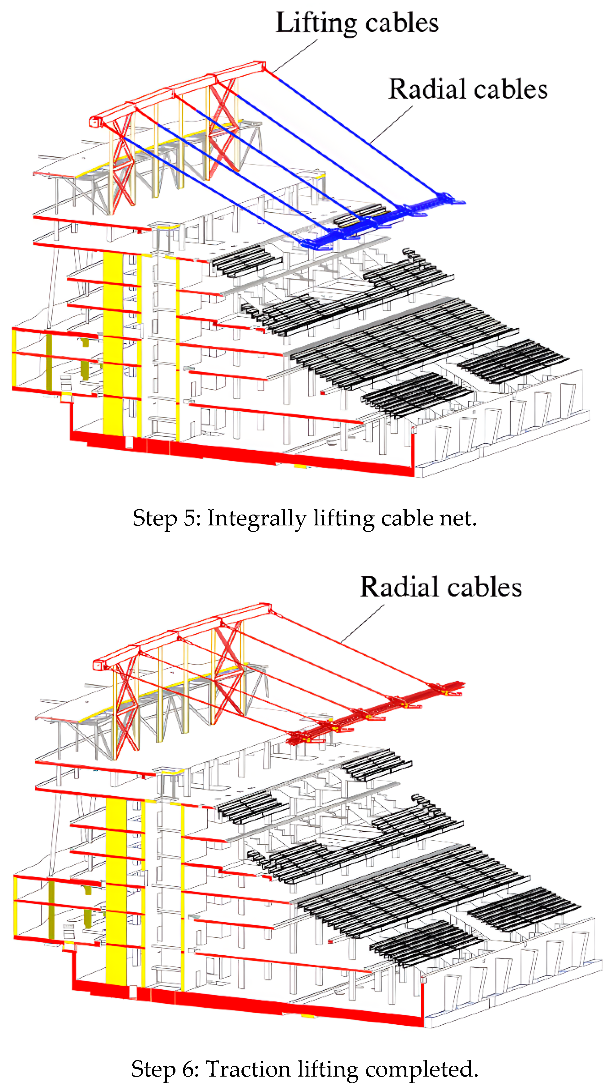
Figure 6.
Schematic diagram of detailed construction steps for roof of Education City Stadium in Qatar.
Figure 6.
Schematic diagram of detailed construction steps for roof of Education City Stadium in Qatar.
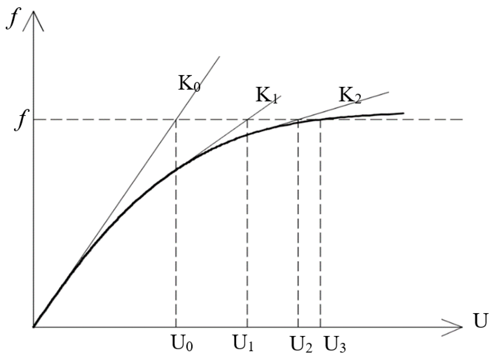
Figure 7.
Nonlinear response of single degree of freedom system [
35].
Figure 7.
Nonlinear response of single degree of freedom system [
35].
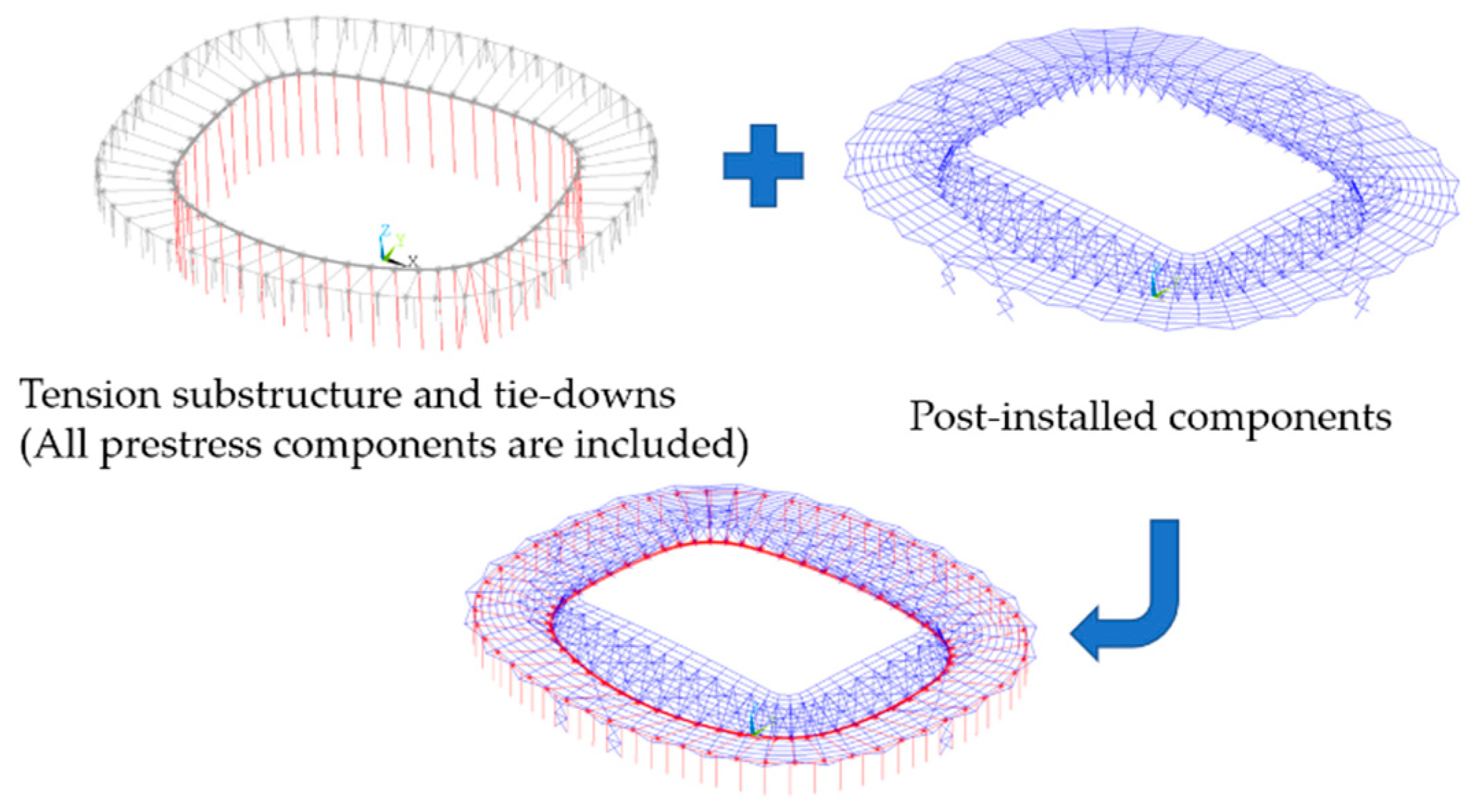
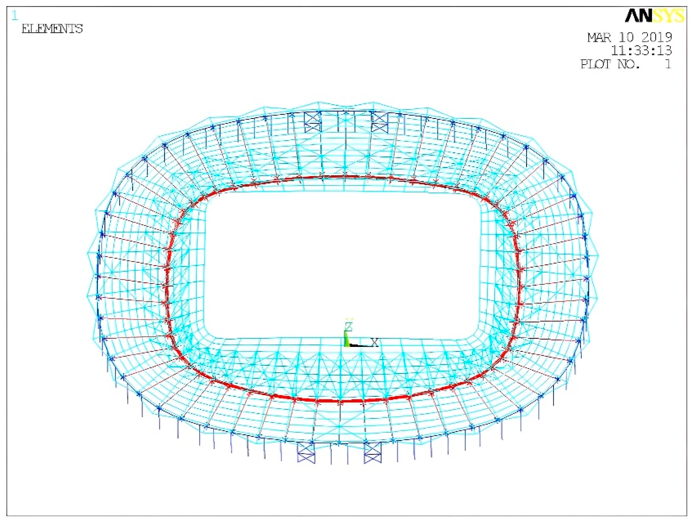
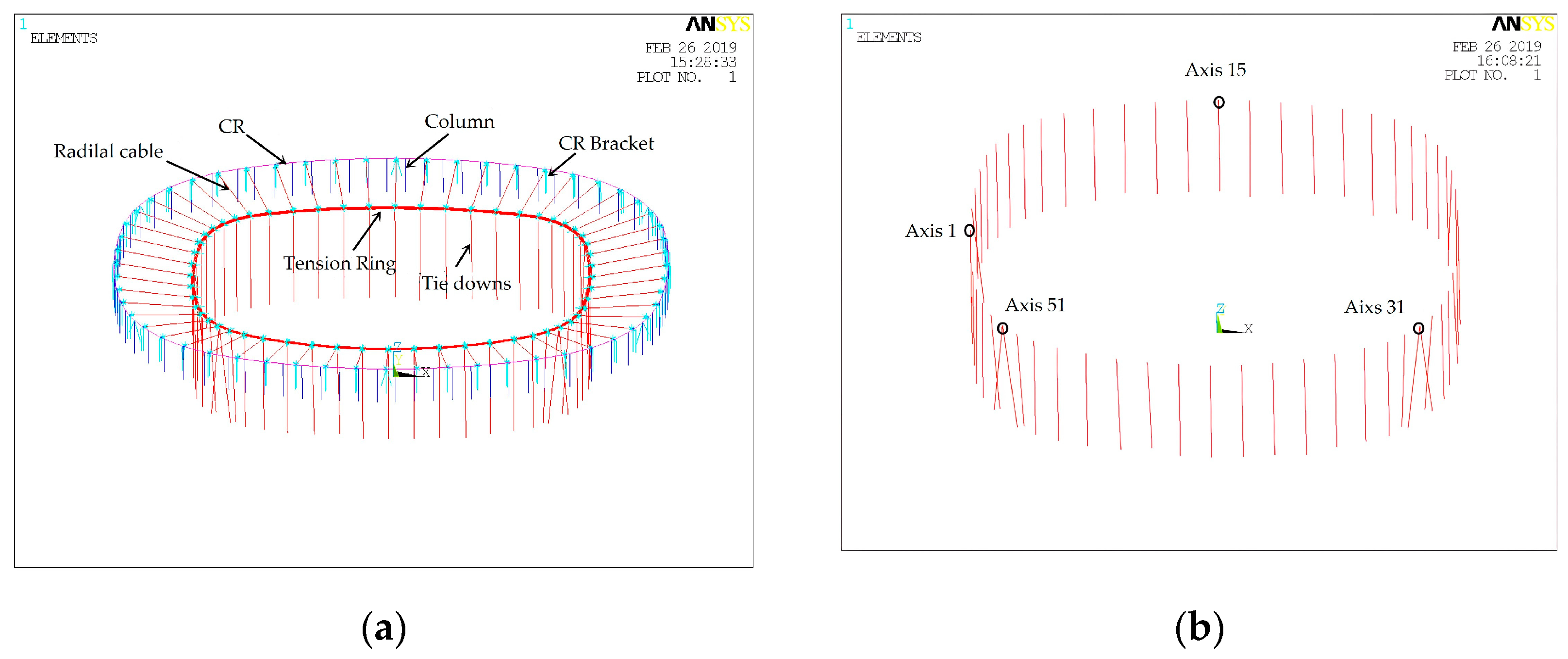
Figure 8.
Finite element model of whole structure.
Figure 8.
Finite element model of whole structure.
Figure 9.
ANSYS calculation results: (a) radial displacement of CR (m); (b) radial displacement of tension ring (m); (c) vertical displacement of tension ring (m); (d) equivalent stress of CR (Pa); (e) radial cable forces (N); (f) tension ring cable forces (N).
Figure 9.
ANSYS calculation results: (a) radial displacement of CR (m); (b) radial displacement of tension ring (m); (c) vertical displacement of tension ring (m); (d) equivalent stress of CR (Pa); (e) radial cable forces (N); (f) tension ring cable forces (N).
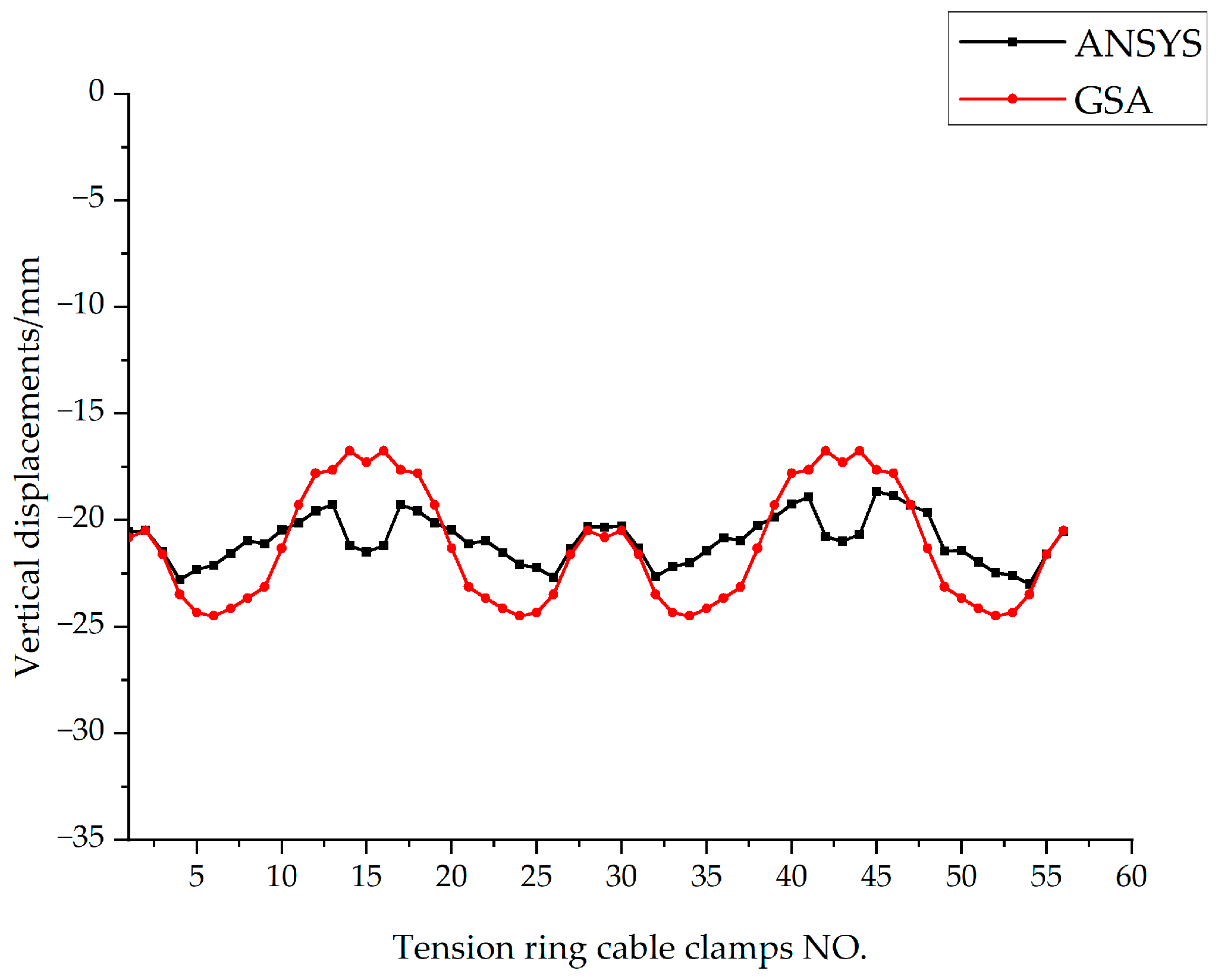
Figure 10.
Comparison curve of vertical displacement of typical tension ring nodes (mm).
Figure 10.
Comparison curve of vertical displacement of typical tension ring nodes (mm).
Figure 11.
Radial beam cantilever ends’ vertical displacements comparison curve (mm).
Figure 11.
Radial beam cantilever ends’ vertical displacements comparison curve (mm).
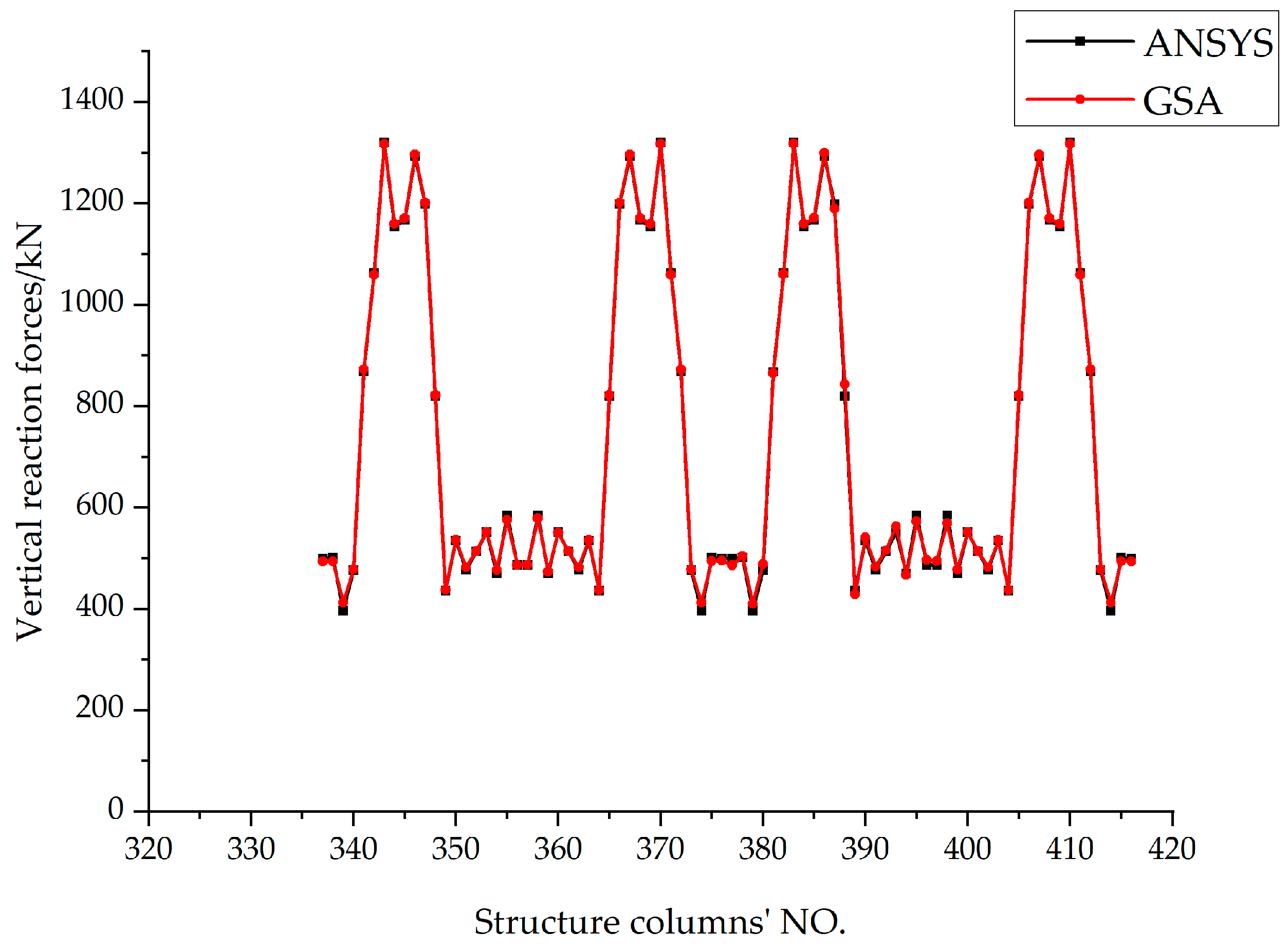
Figure 12.
Comparison curve of vertical reaction forces of structural columns (kN).
Figure 12.
Comparison curve of vertical reaction forces of structural columns (kN).
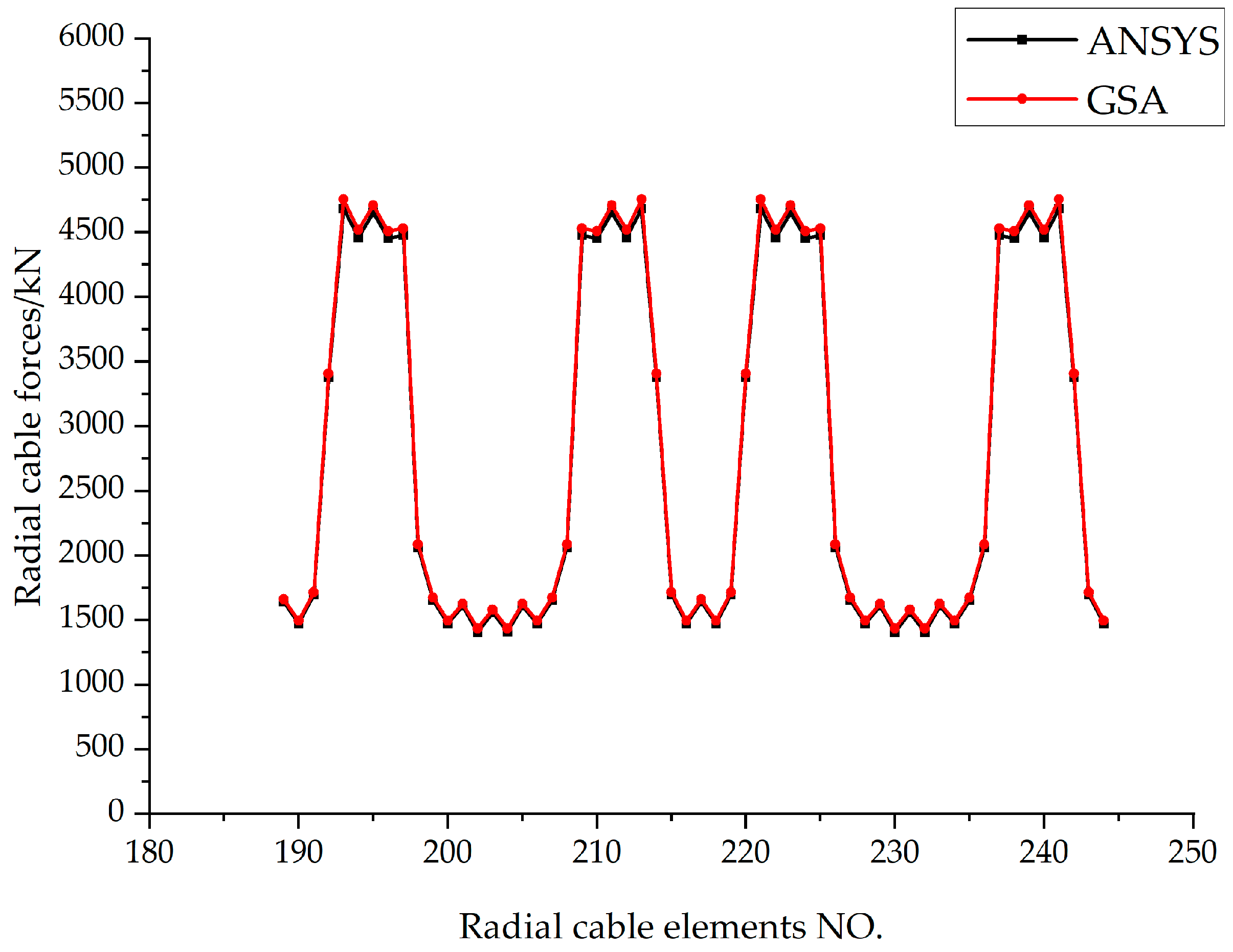
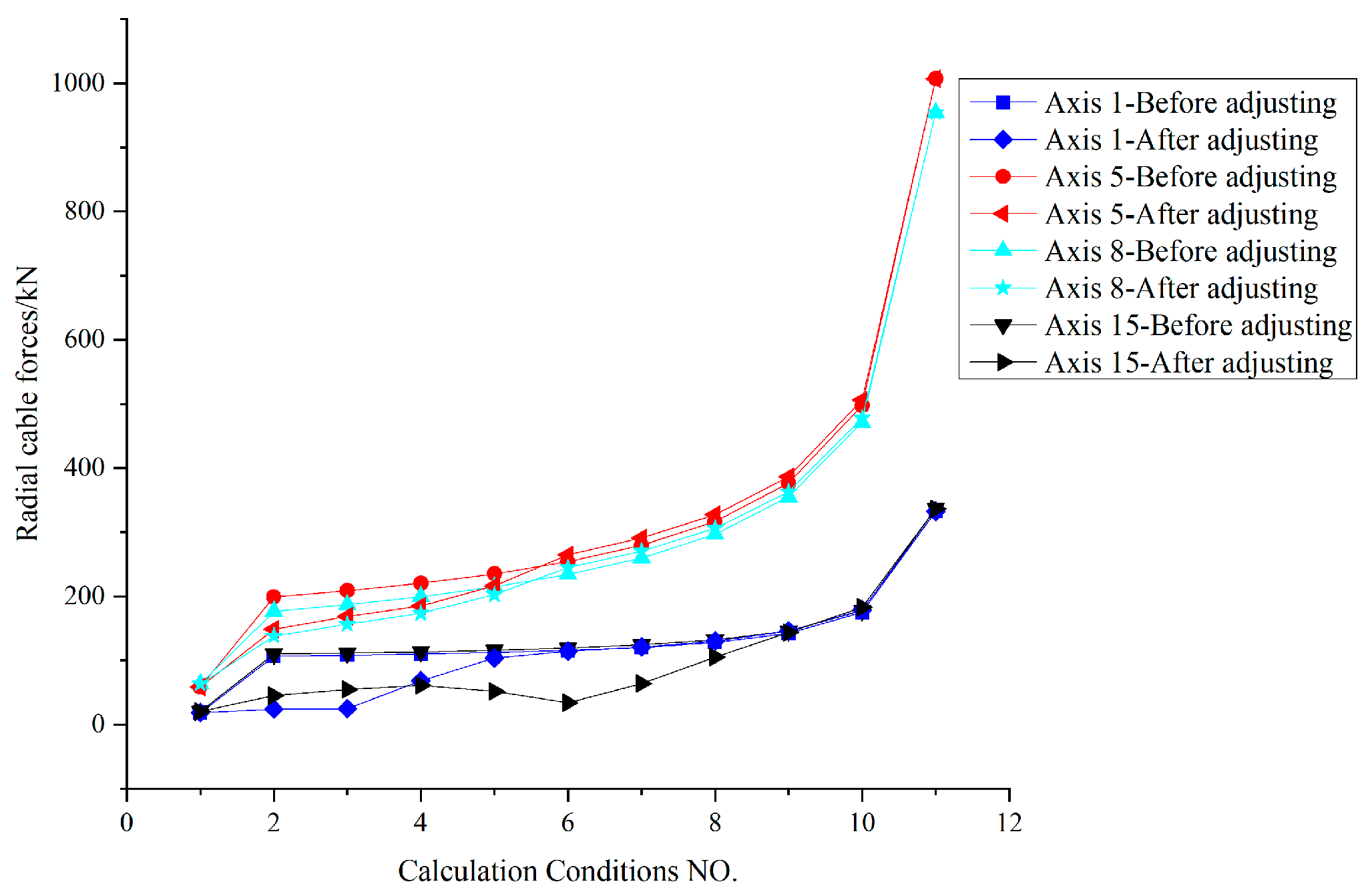
Figure 13.
Comparison curve of radial cable force (kN).
Figure 13.
Comparison curve of radial cable force (kN).
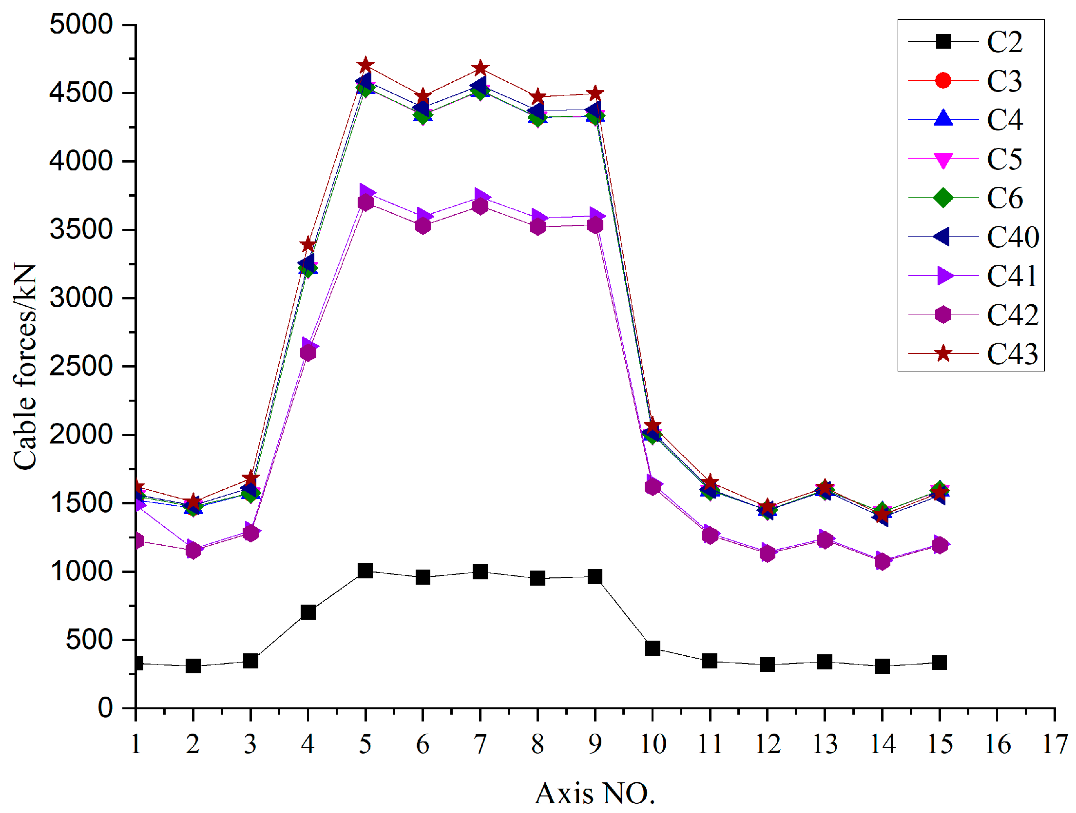
Figure 14.
Comparison curves of tension ring cable forces (kN).
Figure 14.
Comparison curves of tension ring cable forces (kN).
Figure 15.
Traction lifting model (red lines indicate traction cables).
Figure 15.
Traction lifting model (red lines indicate traction cables).
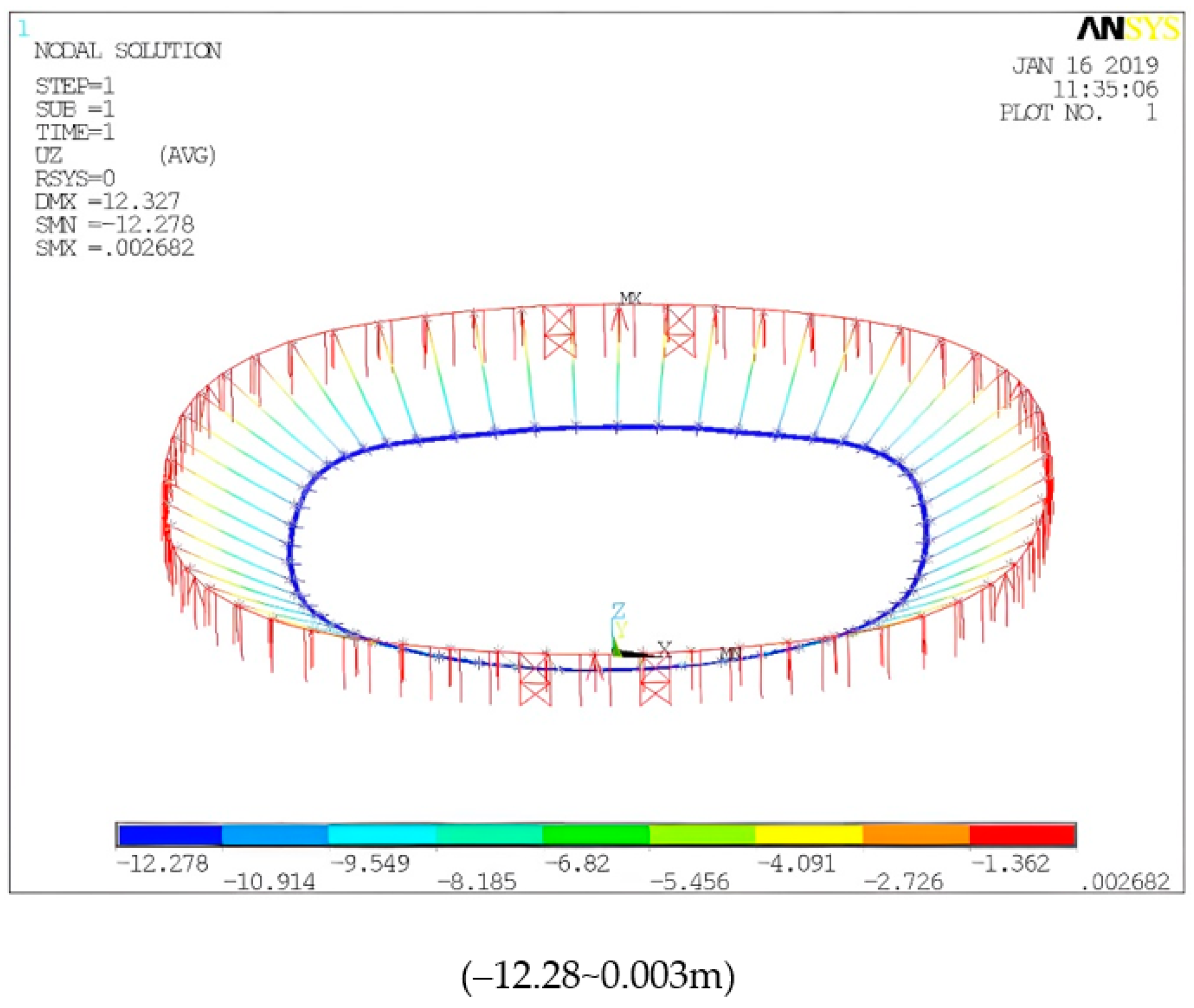
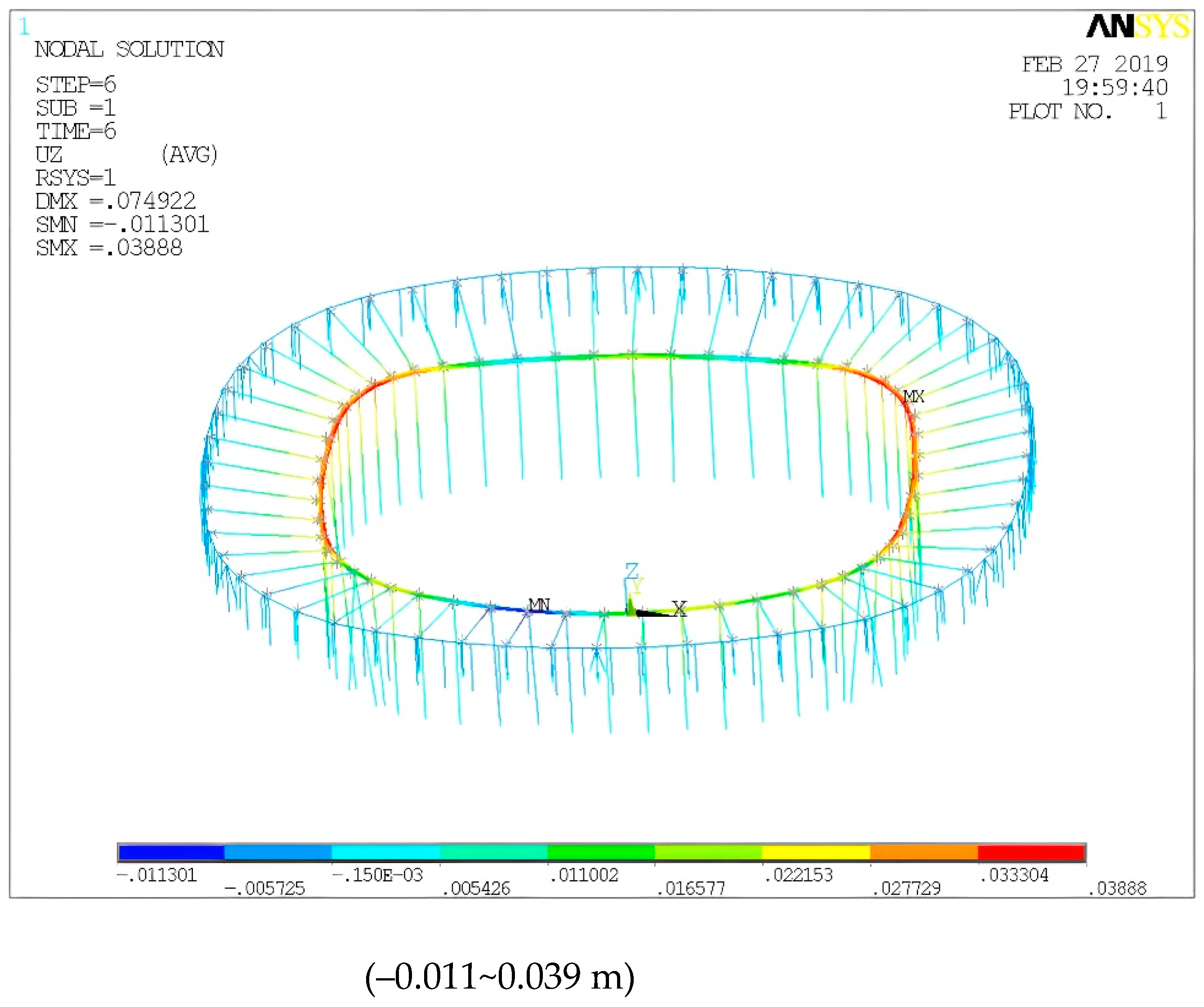
Figure 16.
Typical Uz configuration (m).
Figure 16.
Typical Uz configuration (m).
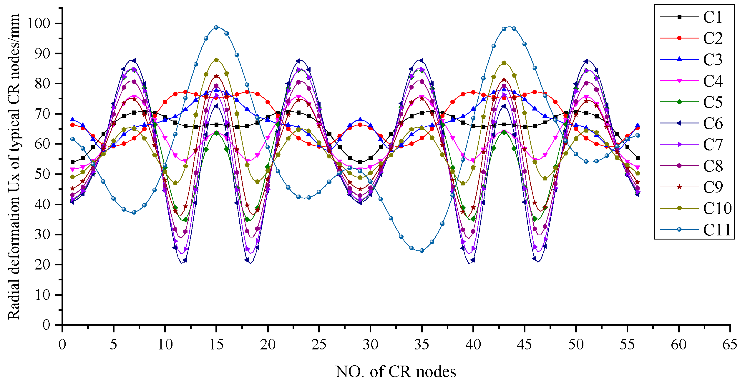
Figure 17.
Radial deformation Ux of CR under local coordinate system at each step.
Figure 17.
Radial deformation Ux of CR under local coordinate system at each step.
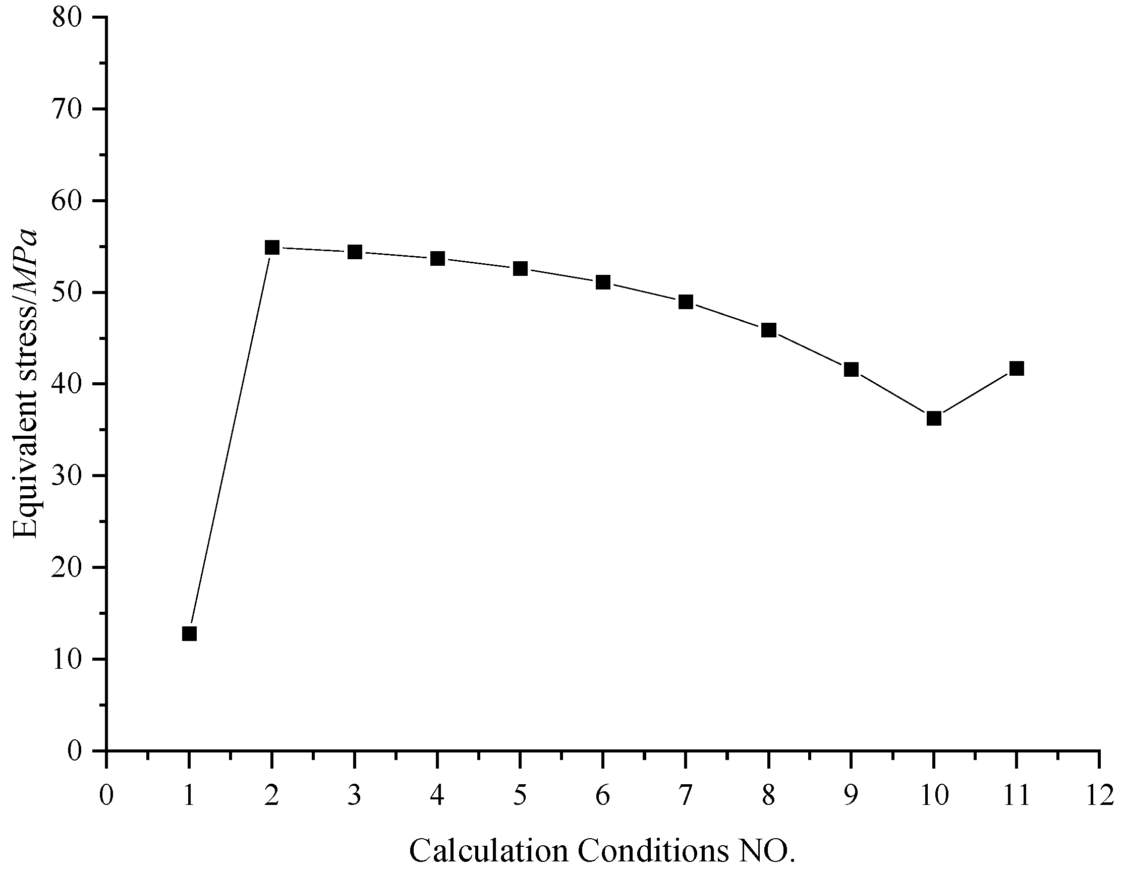
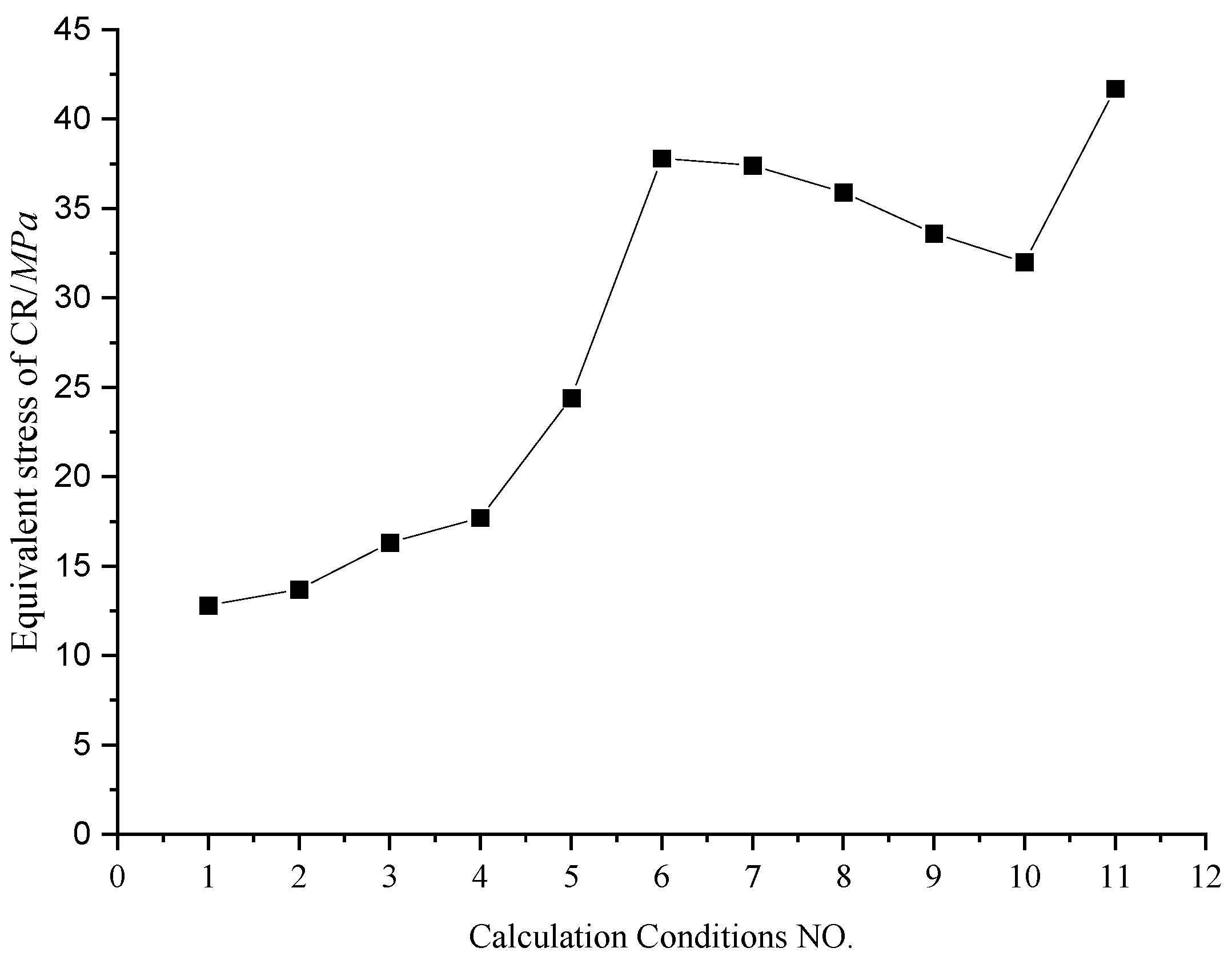
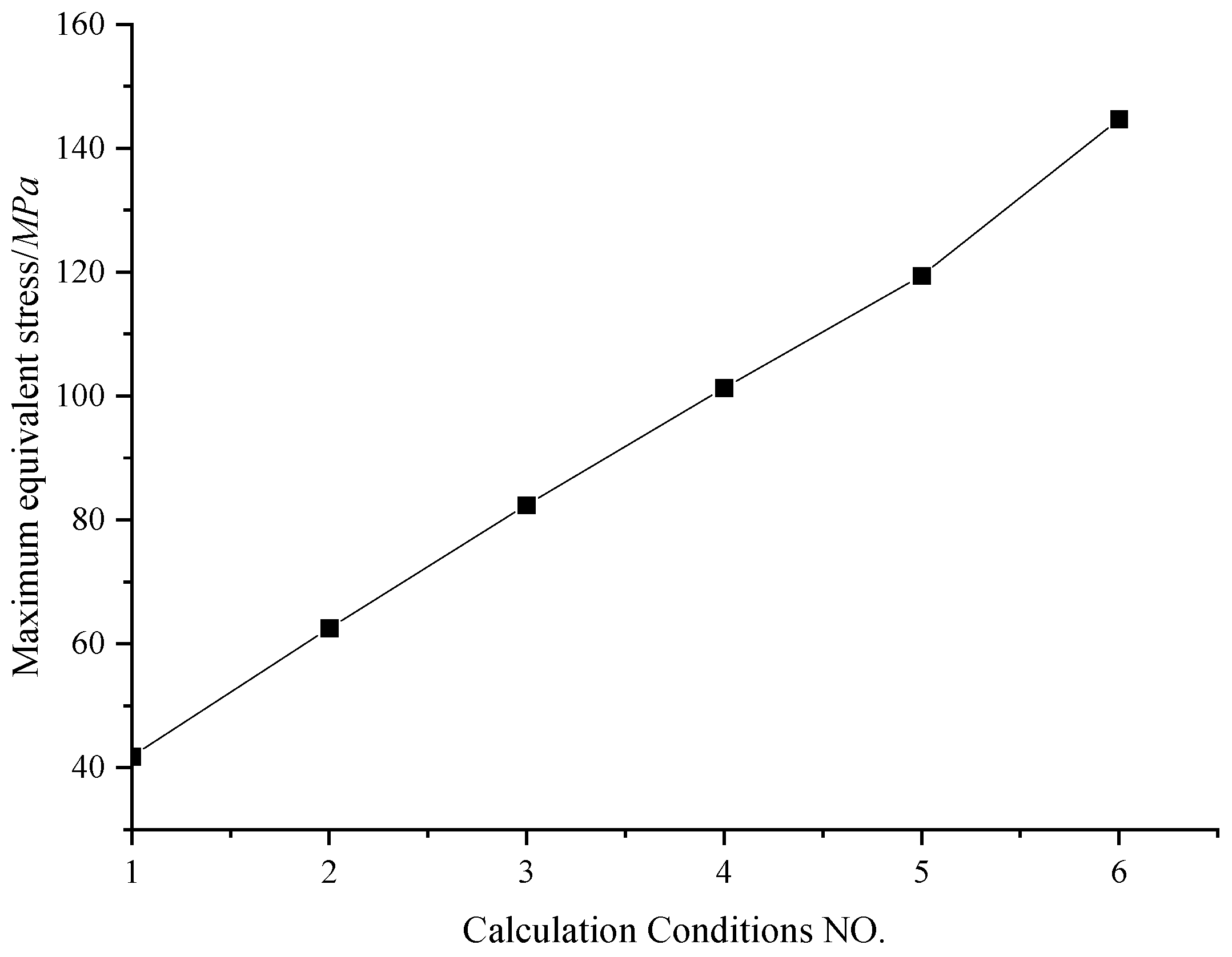
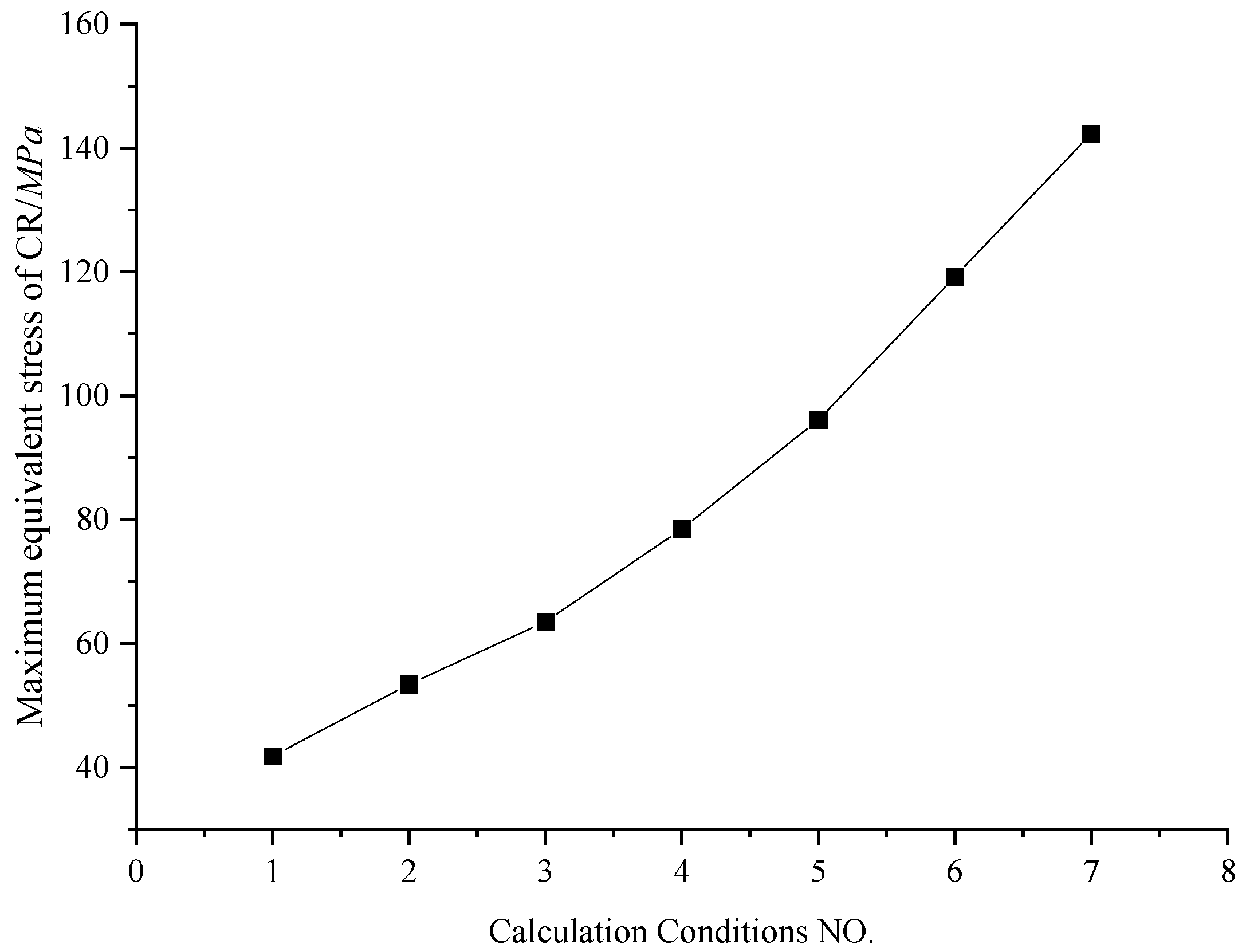
Figure 18.
Maximum equivalent stress curve of CR.
Figure 18.
Maximum equivalent stress curve of CR.
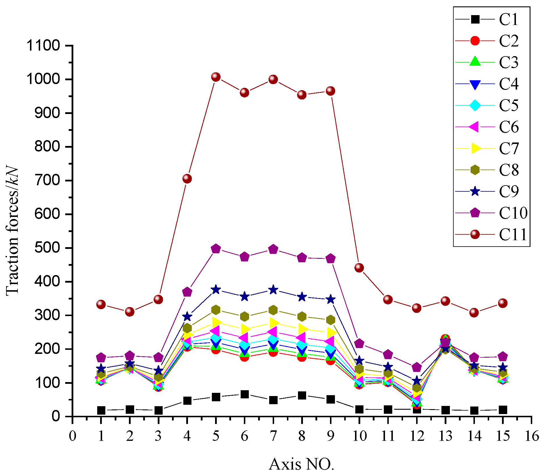
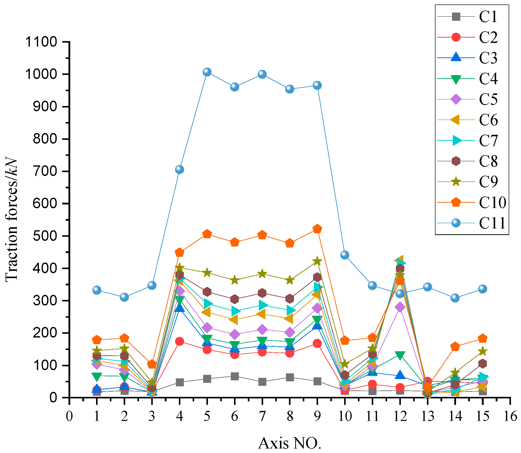
Figure 19.
Variation curve of traction force.
Figure 19.
Variation curve of traction force.
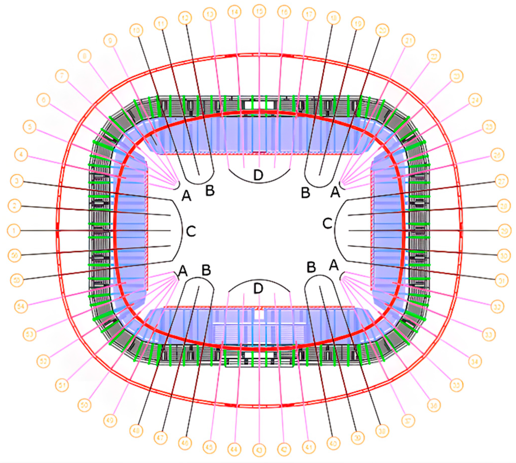
Figure 20.
Schematic diagram of four groups of typical CR brackets.
Figure 20.
Schematic diagram of four groups of typical CR brackets.
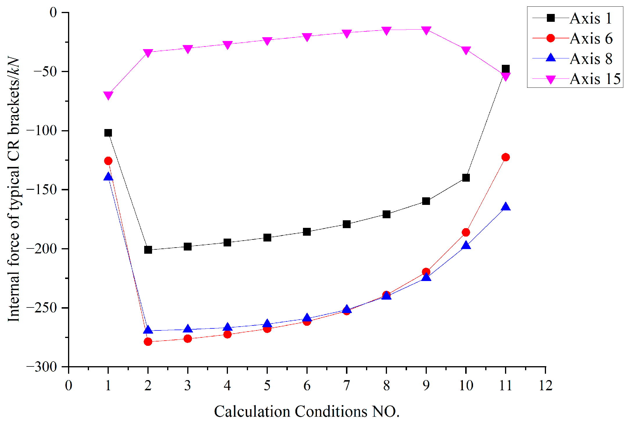
Figure 21.
Variation curve of internal force of typical inner CR brackets.
Figure 21.
Variation curve of internal force of typical inner CR brackets.
Figure 22.
Variation curve of internal force of typical external CR brackets.
Figure 22.
Variation curve of internal force of typical external CR brackets.
Figure 23.
Section division of cable net.
Figure 23.
Section division of cable net.
Figure 24.
Schematic diagram of cumulative sectional traction lifting.
Figure 24.
Schematic diagram of cumulative sectional traction lifting.
Figure 25.
Radial deformation Ux of CR nodes under local coordinate system.
Figure 25.
Radial deformation Ux of CR nodes under local coordinate system.
Figure 26.
Maximum equivalent stress curve of CR.
Figure 26.
Maximum equivalent stress curve of CR.
Figure 27.
Variation curve of traction force during traction lifting.
Figure 27.
Variation curve of traction force during traction lifting.
Figure 28.
Internal force variation curves of four groups of typical inner CR brackets.
Figure 28.
Internal force variation curves of four groups of typical inner CR brackets.
Figure 29.
Internal force variation curves of four groups of typical external CR brackets.
Figure 29.
Internal force variation curves of four groups of typical external CR brackets.
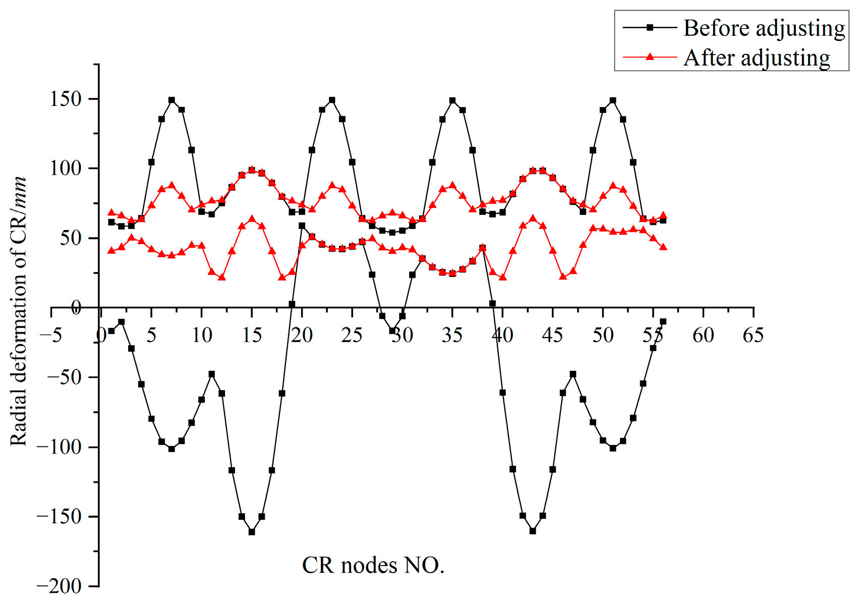
Figure 30.
Envelope diagram of radial deformation of CR before and after adjusting.
Figure 30.
Envelope diagram of radial deformation of CR before and after adjusting.
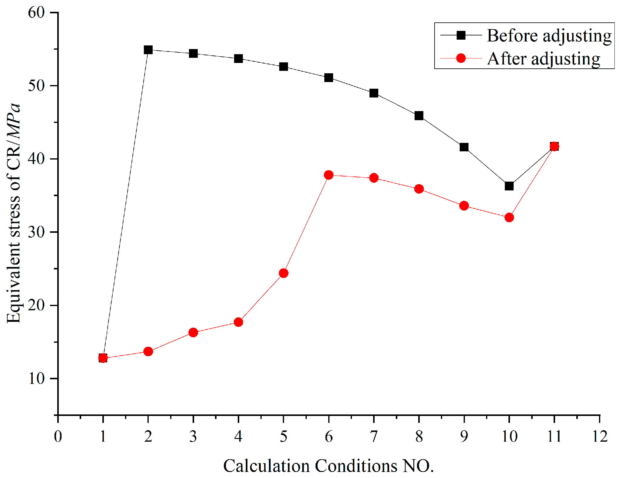
Figure 31.
Maximum equivalent stress of CR before and after adjusting.
Figure 31.
Maximum equivalent stress of CR before and after adjusting.
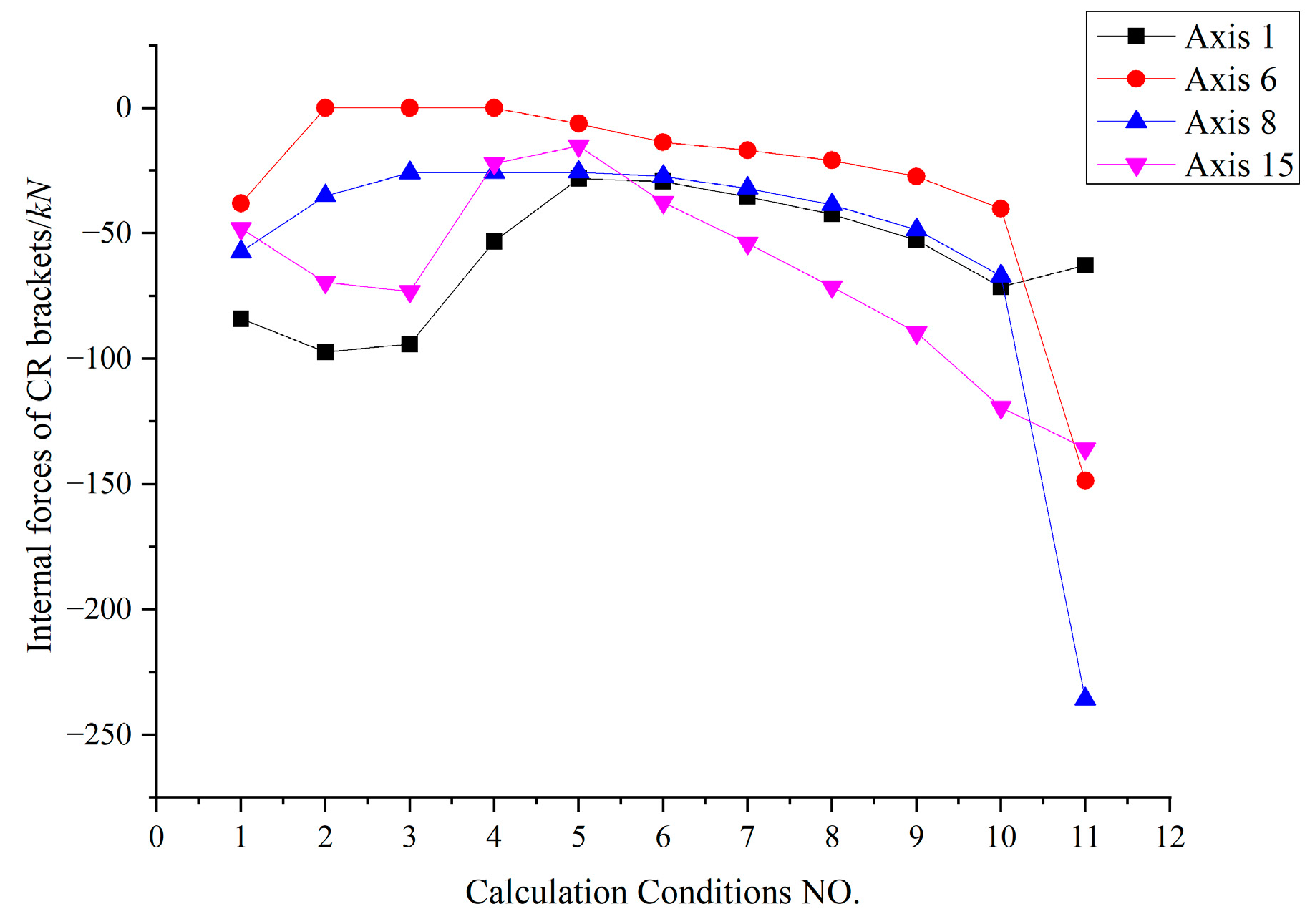
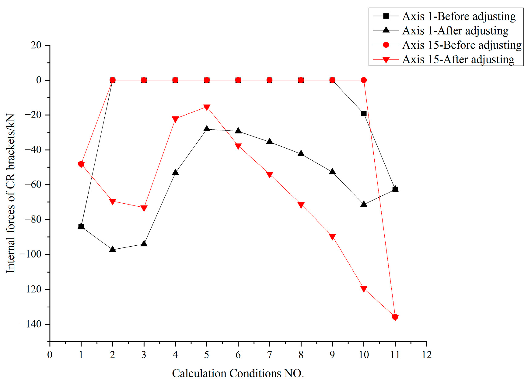
Figure 32.
Internal forces of axis 1 and axis 15 CR external supports before and after adjusting.
Figure 32.
Internal forces of axis 1 and axis 15 CR external supports before and after adjusting.
Figure 33.
Traction cable forces are almost the same before and after adjusting.
Figure 33.
Traction cable forces are almost the same before and after adjusting.
Figure 34.
Tie-down tension analysis model. (a) Whole model; (b) Tie-downs.
Figure 34.
Tie-down tension analysis model. (a) Whole model; (b) Tie-downs.
Figure 35.
Vertical deformation Uz (m) of C6.
Figure 35.
Vertical deformation Uz (m) of C6.
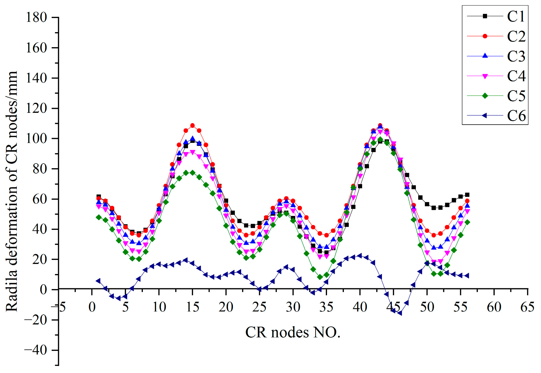
Figure 36.
Radial deformation Ux of CR under various calculation conditions in local coordinate system.
Figure 36.
Radial deformation Ux of CR under various calculation conditions in local coordinate system.
Figure 37.
Maximum equivalent stress curve of CR.
Figure 37.
Maximum equivalent stress curve of CR.
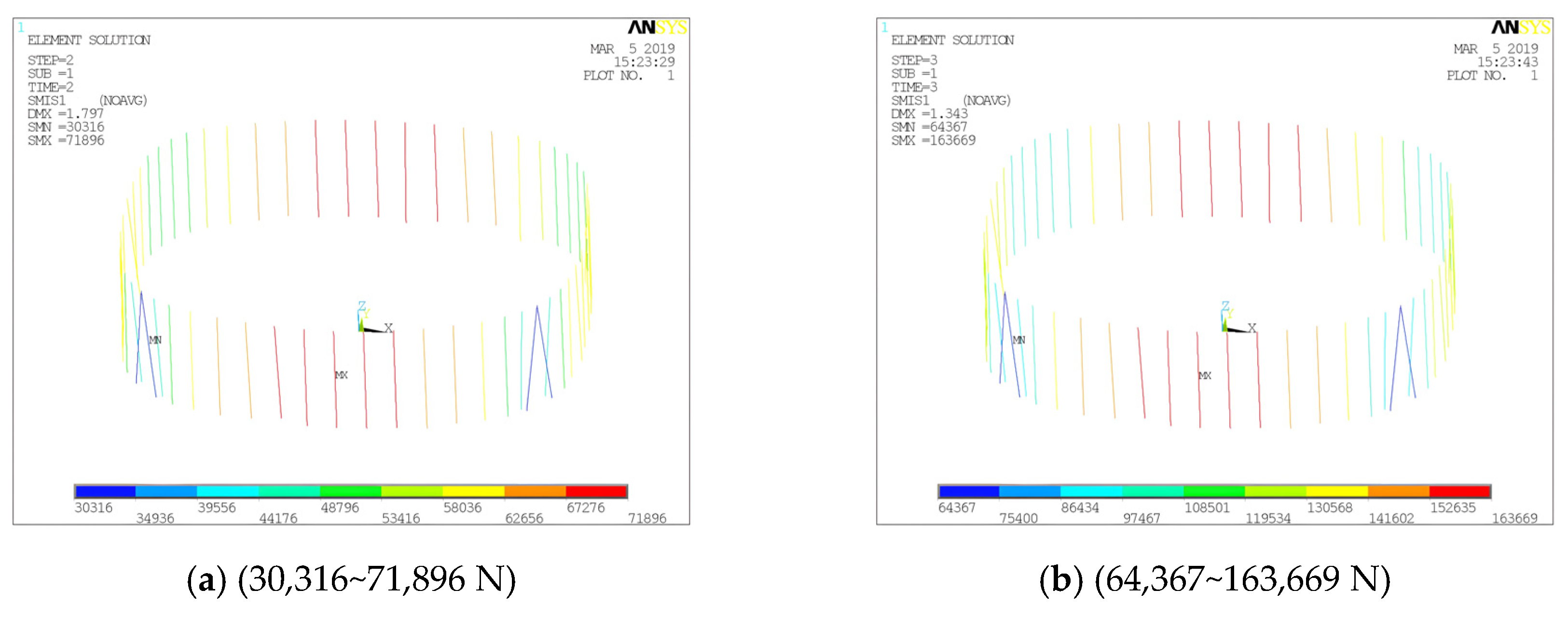
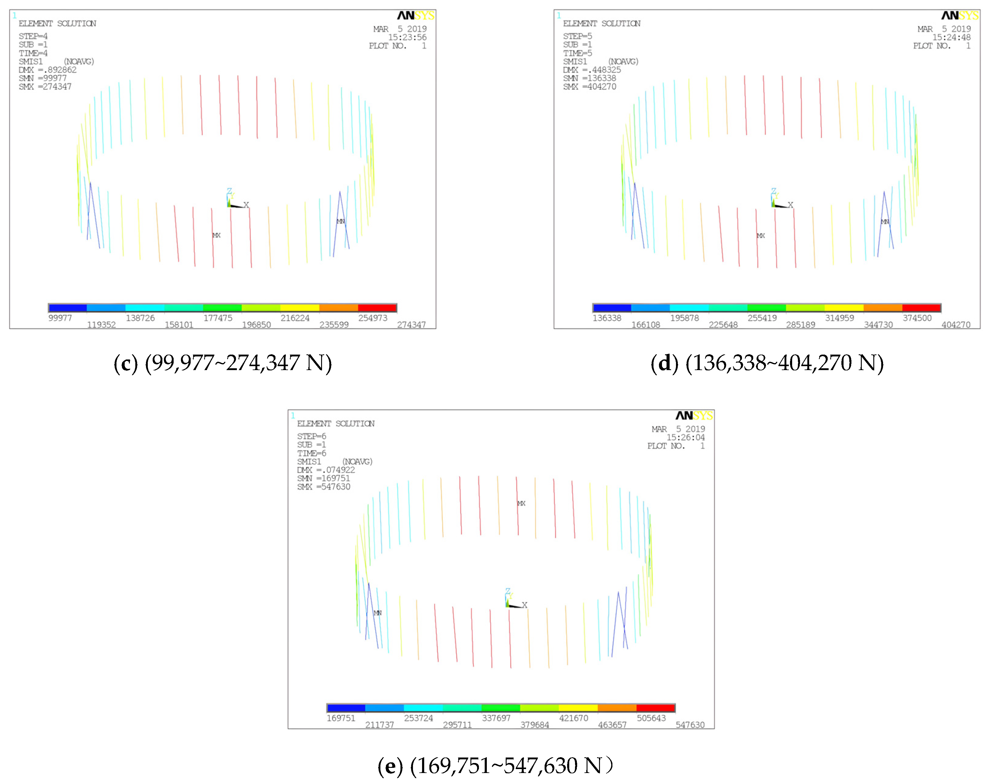
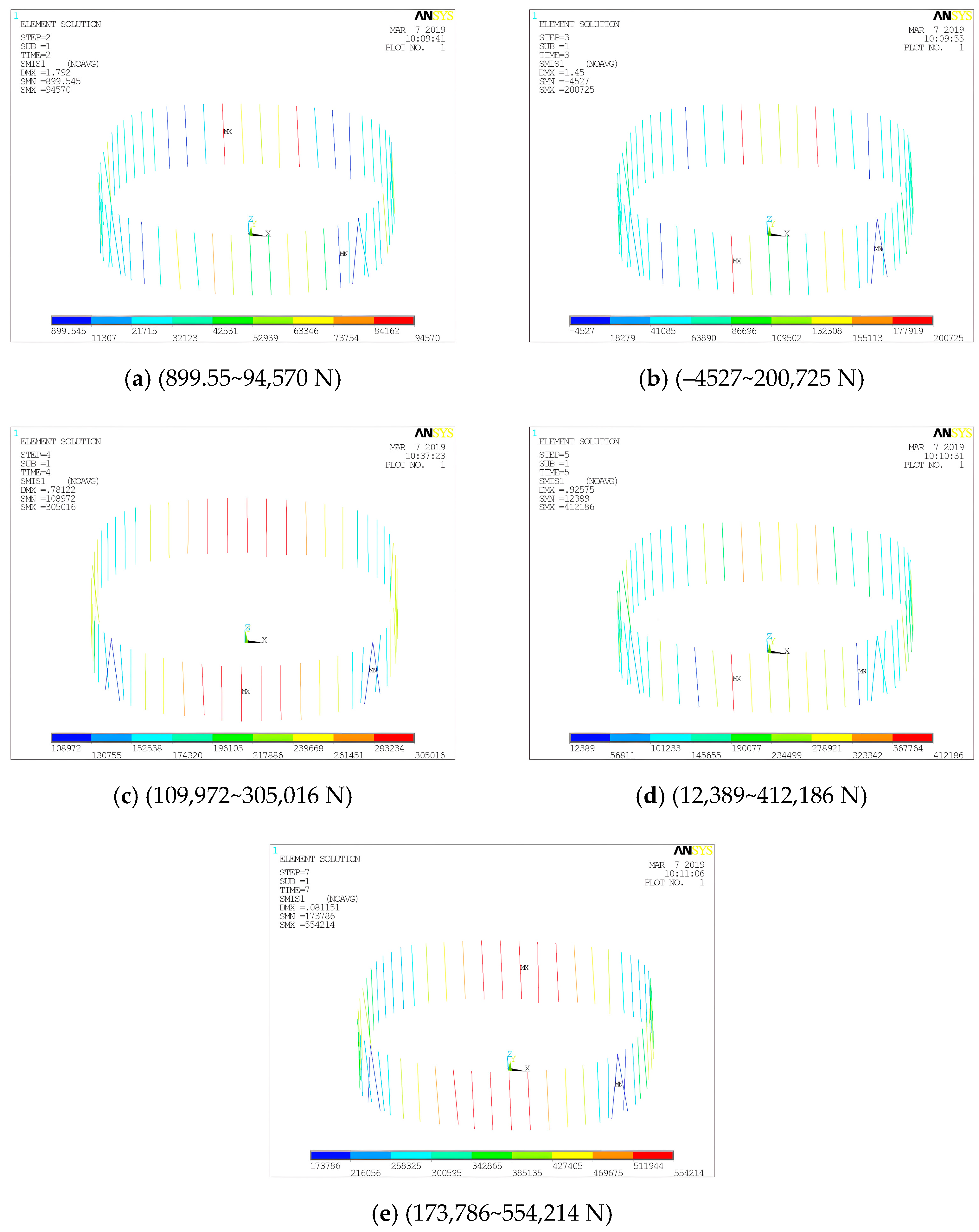
Figure 38.
Tie-down force nephograms (N): (a) C2, (b) C3 (c) C4, (d) C5, (e) C6.
Figure 38.
Tie-down force nephograms (N): (a) C2, (b) C3 (c) C4, (d) C5, (e) C6.
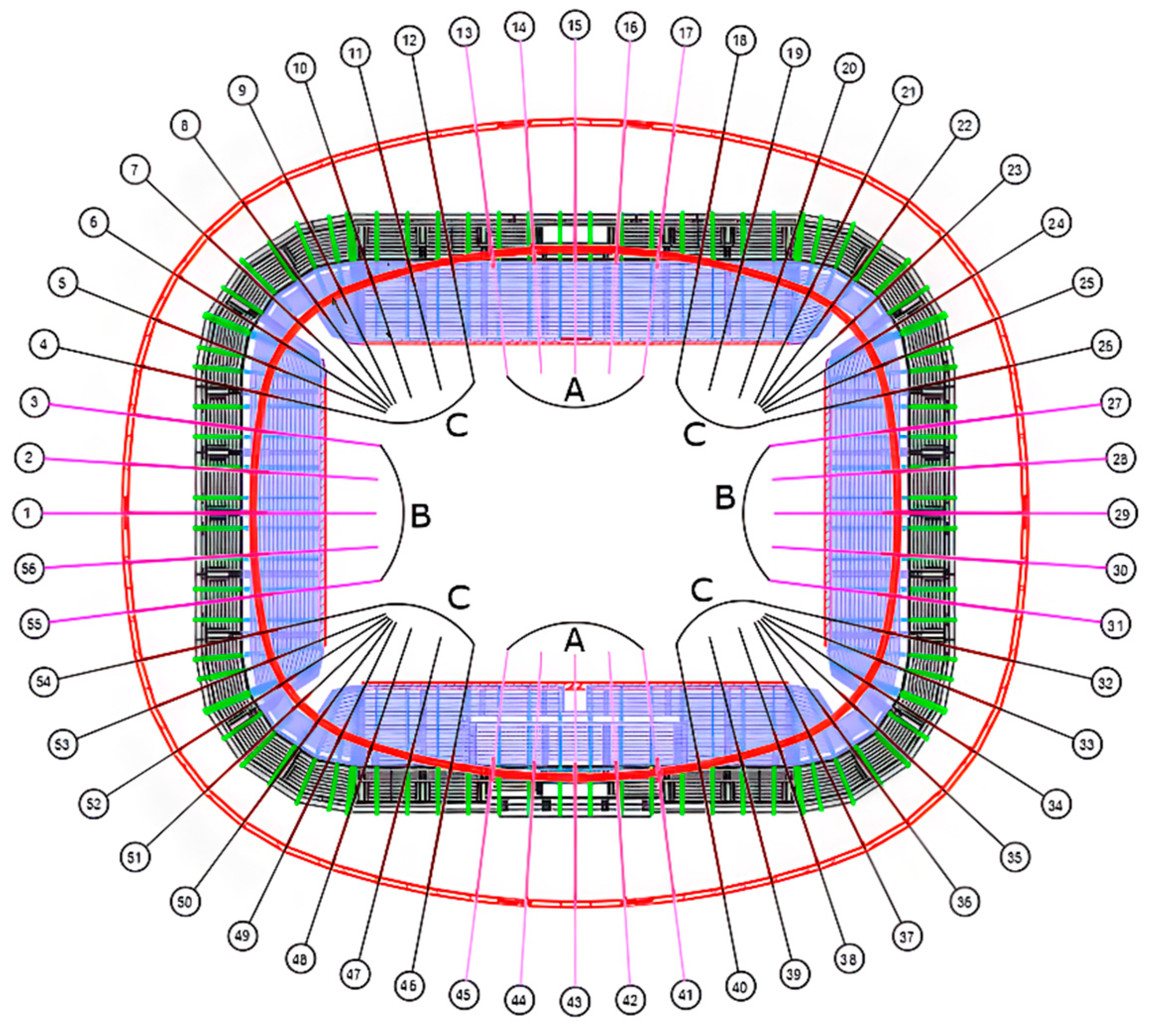
Figure 39.
Division of tie-downs. (1~56 represent the NO. of radial cables corresponding to Axis NO.)
Figure 39.
Division of tie-downs. (1~56 represent the NO. of radial cables corresponding to Axis NO.)
Figure 40.
Radial deformation Ux of CR under various calculation conditions in local coordinate system.
Figure 40.
Radial deformation Ux of CR under various calculation conditions in local coordinate system.
Figure 41.
Maximum equivalent stress curve of CR.
Figure 41.
Maximum equivalent stress curve of CR.
Figure 42.
Tie-down force nephograms (N): (a) C2, (b) C3 (c) C4, (d) C5, (e) C6.
Figure 42.
Tie-down force nephograms (N): (a) C2, (b) C3 (c) C4, (d) C5, (e) C6.
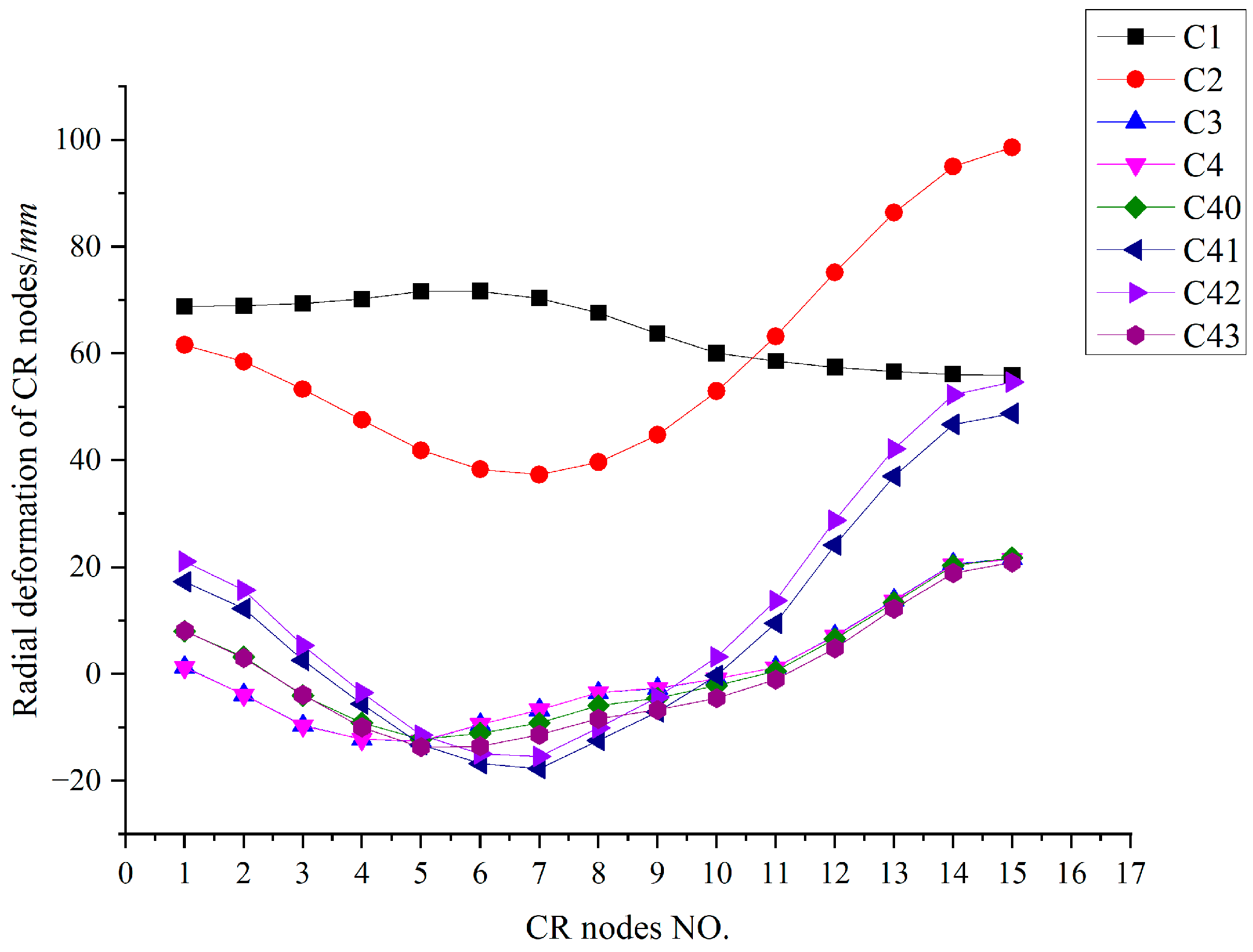
Figure 43.
Envelope diagram of CR radial deformation before and after adjusting.
Figure 43.
Envelope diagram of CR radial deformation before and after adjusting.
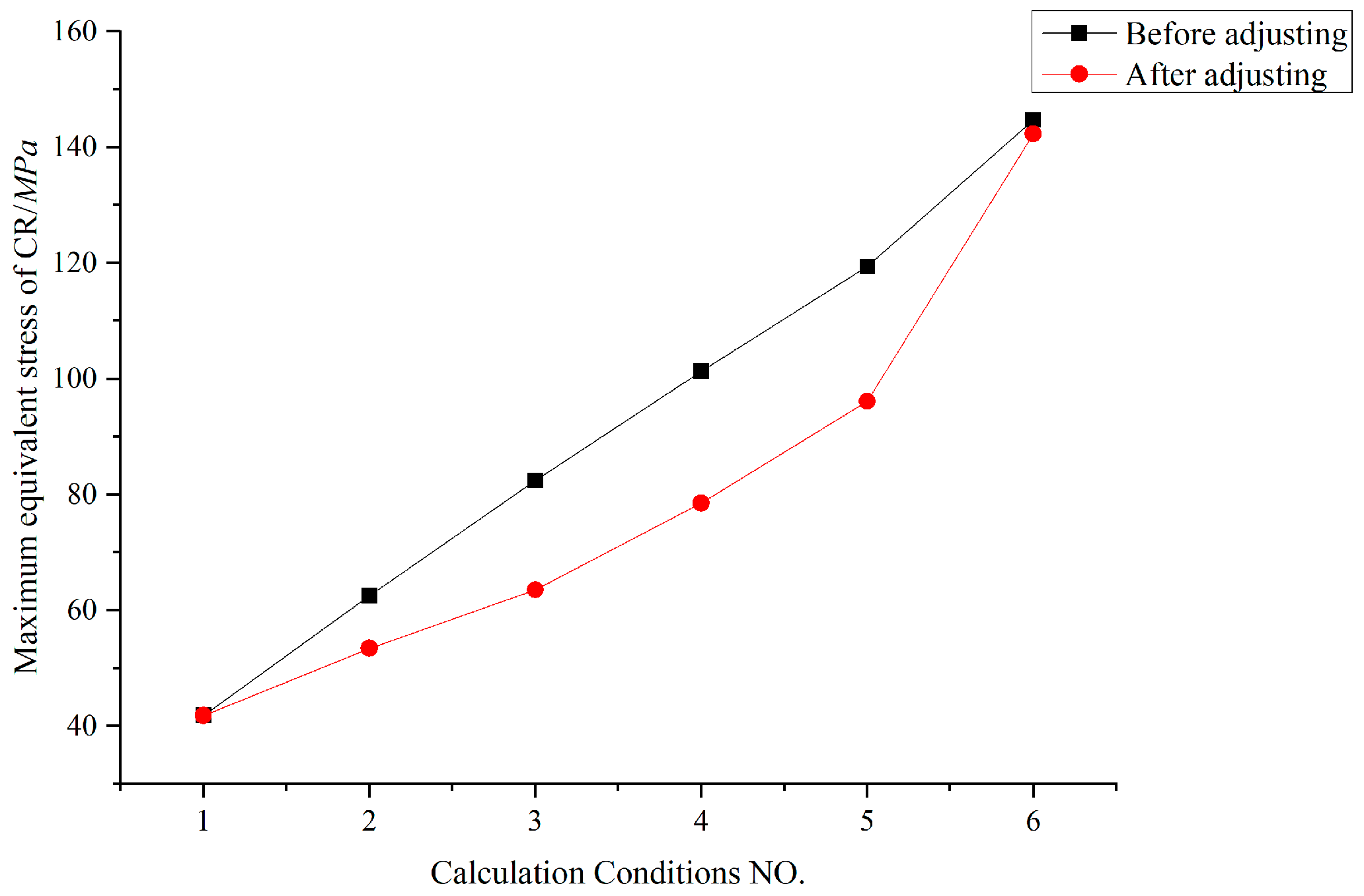
Figure 44.
Maximum equivalent stress of CR before and after adjusting.
Figure 44.
Maximum equivalent stress of CR before and after adjusting.
Figure 45.
Four selected groups of tie-down forces before and after adjusting.
Figure 45.
Four selected groups of tie-down forces before and after adjusting.
Figure 47.
CR radial deformation curve (mm).
Figure 47.
CR radial deformation curve (mm).
Figure 48.
Radial deformation curve of central nodes of tension ring clamps (mm).
Figure 48.
Radial deformation curve of central nodes of tension ring clamps (mm).
Figure 49.
Vertical deformation Uz curve of typical nodes of tension ring (mm).
Figure 49.
Vertical deformation Uz curve of typical nodes of tension ring (mm).
Figure 50.
Tension ring clamp nodes. (1~15 represent the tension ring cable clamps’ nodes NO. corresponding to the axis.)
Figure 50.
Tension ring clamp nodes. (1~15 represent the tension ring cable clamps’ nodes NO. corresponding to the axis.)
Figure 51.
Maximum stress variation curve of four types of components under various calculation conditions (MPa).
Figure 51.
Maximum stress variation curve of four types of components under various calculation conditions (MPa).
Figure 52.
Cable force variation curve of three typical radial cables under various calculation conditions (kN).
Figure 52.
Cable force variation curve of three typical radial cables under various calculation conditions (kN).
Figure 53.
Radial cables. (1~15 represent the radial cables’ NO. corresponding to the axis.)
Figure 53.
Radial cables. (1~15 represent the radial cables’ NO. corresponding to the axis.)
Figure 54.
Variation curve of maximum internal force of each CR bracket (kN).
Figure 54.
Variation curve of maximum internal force of each CR bracket (kN).
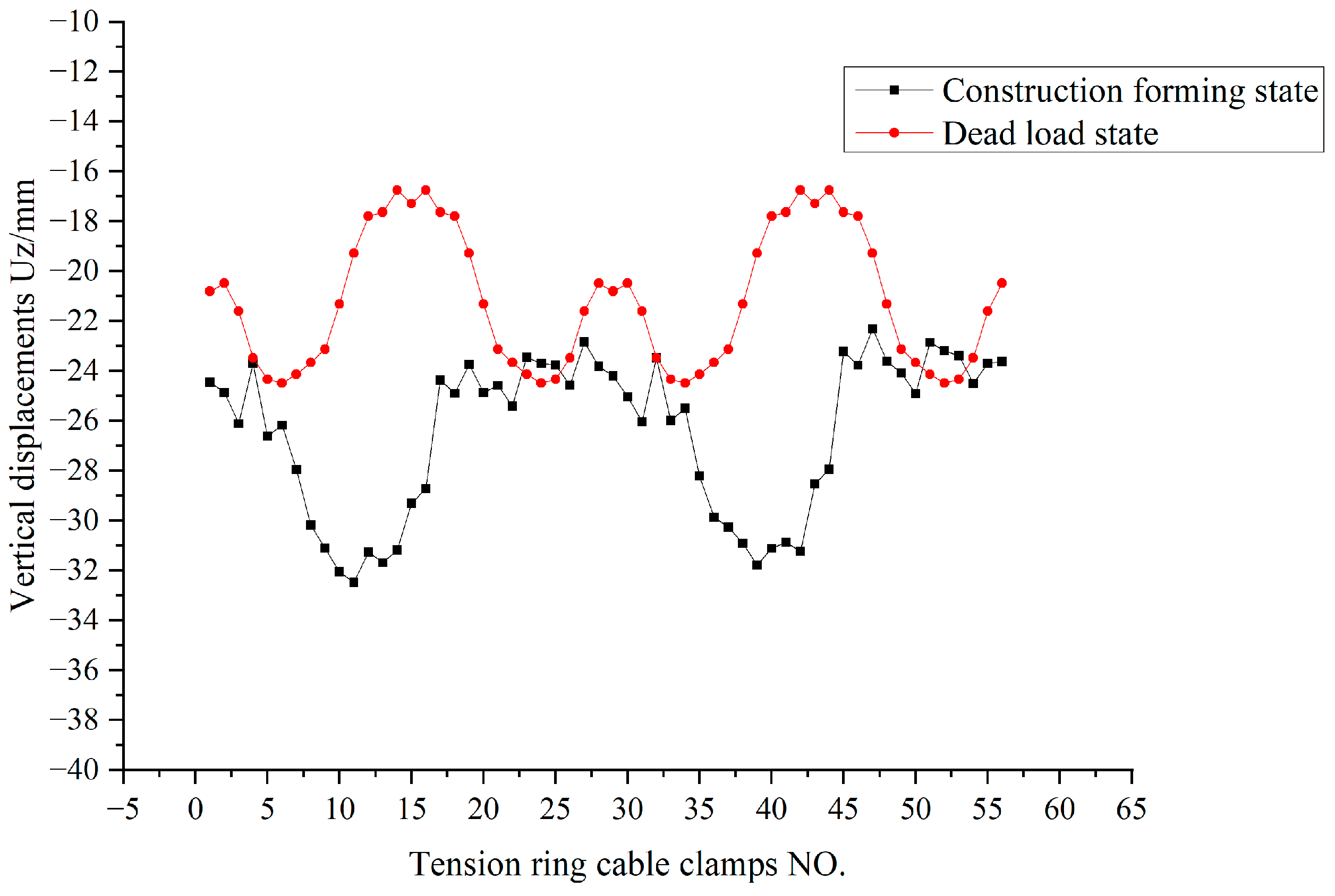
Figure 55.
Comparison curve of vertical deformation of tension ring in two states (mm).
Figure 55.
Comparison curve of vertical deformation of tension ring in two states (mm).
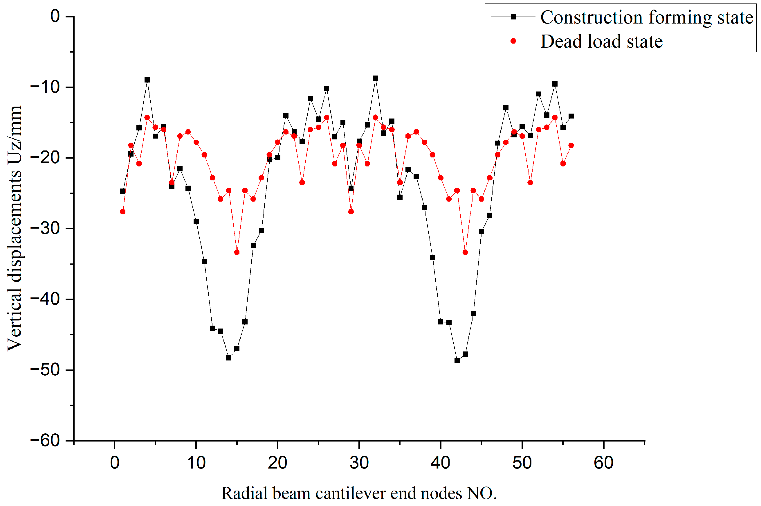
Figure 56.
Comparison curve of vertical deformation of cantilever ends in two states (mm).
Figure 56.
Comparison curve of vertical deformation of cantilever ends in two states (mm).
Figure 57.
Comparison curve of vertical reaction force of structure in two states (kN).
Figure 57.
Comparison curve of vertical reaction force of structure in two states (kN).
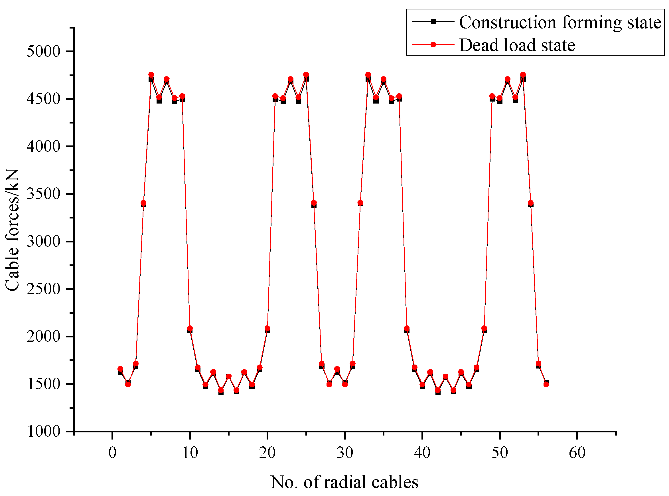
Figure 58.
Comparison curve of radial cable force in two states (kN).
Figure 58.
Comparison curve of radial cable force in two states (kN).
Figure 59.
Comparison curve of tension ring force in two states (kN).
Figure 59.
Comparison curve of tension ring force in two states (kN).
Table 1.
Cable materials and specifications.
Table 1.
Cable materials and specifications.
| | Specification | Cable Section (mm2) | Cable Weight (kg·m−1) |
|---|
| Tension rings | 8D110 | 67,680 | 544 |
| Radial cables | D75 | 3890 | 31.3 |
| D80 | 4420 | 35.5 |
| D90 | 5600 | 45 |
| D115 | 9280 | 74.5 |
| D135 | 12,920 | 104 |
Table 2.
Element types.
| Component | Element Type |
|---|
| Out compression ring | Link8/Beam188 |
| Structure column | Beam188 + Beam44 |
| Cross-braces between structure columns | Link8 |
| Top chord steel grids | Beam188 + Beam44 |
| Cables | Link10 |
| Cable clamps | Beam188 |
| Cable end ear plates | Mass21 |
Table 3.
Statistical table of material characteristics.
Table 3.
Statistical table of material characteristics.
| Parameter | Steel | Cable |
|---|
| E (GPa) | 210 | 165 |
| G (GPa) | 80.8 | | |
| | |
| ρ (kg/m3) | 7850 | 8050 |
| α (1/°C) | 11.7 × 10⁻⁶ | 12.0 × 10⁻⁶ |
Table 4.
Equivalent temperature difference of 1/4 CR.
Table 4.
Equivalent temperature difference of 1/4 CR.
| CR Element | PCR (kN) | | E | A (m2) | ΔT (°C) |
|---|
| 1 | −24,001 | 1.20 × 10⁻⁵ | 2.10 × 10¹¹ | 0.1604 | 59.378 |
| 2 | −24,001 | 1.20 × 10⁻⁵ | 2.10 × 10¹¹ | 0.1604 | 59.378 |
| 3 | −24,001 | 1.20 × 10⁻⁵ | 2.10 × 10¹¹ | 0.1604 | 59.378 |
| 4 | −24,025 | 1.20 × 10⁻⁵ | 2.10 × 10¹¹ | 0.1604 | 59.437 |
| 5 | −24,025 | 1.20 × 10⁻⁵ | 2.10 × 10¹¹ | 0.1604 | 59.437 |
| 6 | −24,015 | 1.20 × 10⁻⁵ | 2.10 × 10¹¹ | 0.1866 | 51.071 |
| 7 | −24,015 | 1.20 × 10⁻⁵ | 2.10 × 10¹¹ | 0.1866 | 51.071 |
| 8 | −24,015 | 1.20 × 10⁻⁵ | 2.10 × 10¹¹ | 0.1866 | 51.071 |
| 9 | −23,964 | 1.20 × 10⁻⁵ | 2.10 × 10¹¹ | 0.25 | 38.038 |
| 10 | −23,964 | 1.20 × 10⁻⁵ | 2.10 × 10¹¹ | 0.25 | 38.038 |
| 11 | −24,014 | 1.20 × 10⁻⁵ | 2.10 × 10¹¹ | 0.25 | 38.117 |
| 12 | −24,014 | 1.20 × 10⁻⁵ | 2.10 × 10¹¹ | 0.25 | 38.117 |
| 13 | −23,972 | 1.20 × 10⁻⁵ | 2.10 × 10¹¹ | 0.25 | 38.051 |
| 14 | −23,972 | 1.20 × 10⁻⁵ | 2.10 × 10¹¹ | 0.25 | 38.051 |
| 15 | −24,013 | 1.20 × 10⁻⁵ | 2.10 × 10¹¹ | 0.25 | 38.116 |
| 16 | −24,013 | 1.20 × 10⁻⁵ | 2.10 × 10¹¹ | 0.25 | 38.116 |
| 17 | −23,971 | 1.20 × 10⁻⁵ | 2.10 × 10¹¹ | 0.25 | 38.049 |
| 18 | −23,971 | 1.20 × 10⁻⁵ | 2.10 × 10¹¹ | 0.25 | 38.049 |
| 19 | −24,012 | 1.20 × 10⁻⁵ | 2.10 × 10¹¹ | 0.2128 | 44.777 |
| 20 | −24,012 | 1.20 × 10⁻⁵ | 2.10 × 10¹¹ | 0.2128 | 44.777 |
| 21 | −23,966 | 1.20 × 10⁻⁵ | 2.10 × 10¹¹ | 0.1604 | 59.291 |
| 22 | −23,966 | 1.20 × 10⁻⁵ | 2.10 × 10¹¹ | 0.1604 | 59.291 |
| 23 | −23,966 | 1.20 × 10⁻⁵ | 2.10 × 10¹¹ | 0.1604 | 59.291 |
| 24 | −24,011 | 1.20 × 10⁻⁵ | 2.10 × 10¹¹ | 0.1604 | 59.403 |
| 25 | −24,011 | 1.20 × 10⁻⁵ | 2.10 × 10¹¹ | 0.1604 | 59.403 |
| 26 | −23,964 | 1.20 × 10⁻⁵ | 2.10 × 10¹¹ | 0.1604 | 59.286 |
| 27 | −23,964 | 1.20 × 10⁻⁵ | 2.10 × 10¹¹ | 0.1604 | 59.286 |
| 28 | −23,964 | 1.20 × 10⁻⁵ | 2.10 × 10¹¹ | 0.1604 | 59.286 |
| 29 | −24,011 | 1.20 × 10⁻⁵ | 2.10 × 10¹¹ | 0.1604 | 59.403 |
| 30 | −24,011 | 1.20 × 10⁻⁵ | 2.10 × 10¹¹ | 0.1604 | 59.403 |
| 31 | −23,979 | 1.20 × 10⁻⁵ | 2.10 × 10¹¹ | 0.1604 | 59.323 |
| 32 | −23,979 | 1.20 × 10⁻⁵ | 2.10 × 10¹¹ | 0.1604 | 59.323 |
| 33 | −23,979 | 1.20 × 10⁻⁵ | 2.10 × 10¹¹ | 0.1604 | 59.323 |
| 34 | −23,979 | 1.20 × 10⁻⁵ | 2.10 × 10¹¹ | 0.1604 | 59.323 |
Table 5.
Equivalent temperature difference of 1/4 radial cables.
Table 5.
Equivalent temperature difference of 1/4 radial cables.
| Radial Cable Axis | Pr/kN | | E | A/mm2 | ΔT/°C |
|---|
| 1 | 1648 | 1.20 × 10⁻⁵ | 2.00 × 10¹¹ | 3671.7 | −187.02 |
| 2 | 1476 | 1.20 × 10⁻⁵ | 2.00 × 10¹¹ | 3200.5 | −192.16 |
| 3 | 1698 | 1.20 × 10⁻⁵ | 2.00 × 10¹¹ | 3671.7 | −192.69 |
| 4 | 3381 | 1.20 × 10⁻⁵ | 2.00 × 10¹¹ | 7559.5 | −186.35 |
| 5 | 4715 | 1.20 × 10⁻⁵ | 2.00 × 10¹¹ | 10,198.4 | −192.64 |
| 6 | 4481 | 1.20 × 10⁻⁵ | 2.00 × 10¹¹ | 10,198.4 | −183.08 |
| 7 | 4668 | 1.20 × 10⁻⁵ | 2.00 × 10¹¹ | 10,198.4 | −190.72 |
| 8 | 4466 | 1.20 × 10⁻⁵ | 2.00 × 10¹¹ | 10,198.4 | −182.46 |
| 9 | 4494 | 1.20 × 10⁻⁵ | 2.00 × 10¹¹ | 10,198.4 | −183.61 |
| 10 | 2069 | 1.20 × 10⁻⁵ | 2.00 × 10¹¹ | 4614.2 | −186.83 |
| 11 | 1659 | 1.20 × 10⁻⁵ | 2.00 × 10¹¹ | 3671.7 | −188.26 |
| 12 | 1478 | 1.20 × 10⁻⁵ | 2.00 × 10¹¹ | 3200.5 | −192.42 |
| 13 | 1615 | 1.20 × 10⁻⁵ | 2.00 × 10¹¹ | 3671.7 | −183.27 |
| 14 | 1418 | 1.20 × 10⁻⁵ | 2.00 × 10¹¹ | 3200.5 | −184.61 |
| 15 | 1570 | 1.20 × 10⁻⁵ | 2.00 × 10¹¹ | 3671.7 | −178.16 |
Table 6.
Calculation conditions during synchronous equal proportion integral lifting.
Table 6.
Calculation conditions during synchronous equal proportion integral lifting.
| Calculation Condition | State |
|---|
| C1 | Table net laid on stand |
| C2 | Traction cable length reduced by 10% |
| C3 | Traction cable length reduced by 20% |
| C4 | Traction cable length reduced by 30% |
| C5 | Traction cable length reduced by 40% |
| C6 | Traction cable length reduced by 50% |
| C7 | Traction cable length reduced by 60% |
| C8 | Traction cable length reduced by 70% |
| C9 | Traction cable length reduced by 80% |
| C10 | Traction cable length reduced by 90% |
| C11 | Traction lifting completed (100%) |
Table 7.
Length of traction cable under various calculation conditions (m).
Table 7.
Length of traction cable under various calculation conditions (m).
| Axis | C1 | C2 | C3 | C4 | C5 | C6 | C7 | C8 | C9 | C10 | C11 |
|---|
| 1 | 13.85 | 12.47 | 11.08 | 9.70 | 8.31 | 6.93 | 5.54 | 4.16 | 2.77 | 1.39 | 0 |
| 2 | 13.82 | 12.44 | 11.06 | 9.67 | 8.29 | 6.91 | 5.53 | 4.15 | 2.76 | 1.38 | 0 |
| 3 | 14.47 | 13.02 | 11.58 | 10.13 | 8.68 | 7.24 | 5.79 | 4.34 | 2.89 | 1.45 | 0 |
| 4 | 14.73 | 13.26 | 11.78 | 10.31 | 8.84 | 7.37 | 5.89 | 4.42 | 2.95 | 1.47 | 0 |
| 5 | 15.42 | 13.88 | 12.34 | 10.79 | 9.25 | 7.71 | 6.17 | 4.63 | 3.08 | 1.54 | 0 |
| 6 | 15.89 | 14.30 | 12.71 | 11.12 | 9.53 | 7.95 | 6.36 | 4.77 | 3.18 | 1.59 | 0 |
| 7 | 16.06 | 14.45 | 12.85 | 11.24 | 9.64 | 8.03 | 6.42 | 4.82 | 3.21 | 1.61 | 0 |
| 8 | 16.05 | 14.45 | 12.84 | 11.24 | 9.63 | 8.03 | 6.42 | 4.82 | 3.21 | 1.61 | 0 |
| 9 | 15.77 | 14.19 | 12.62 | 11.04 | 9.46 | 7.89 | 6.31 | 4.73 | 3.15 | 1.58 | 0 |
| 10 | 15.08 | 13.57 | 12.06 | 10.56 | 9.05 | 7.54 | 6.03 | 4.52 | 3.02 | 1.51 | 0 |
| 11 | 14.00 | 12.60 | 11.20 | 9.80 | 8.40 | 7.00 | 5.60 | 4.20 | 2.80 | 1.40 | 0 |
| 12 | 12.93 | 11.64 | 10.34 | 9.05 | 7.76 | 6.47 | 5.17 | 3.88 | 2.59 | 1.29 | 0 |
| 13 | 10.64 | 9.58 | 8.51 | 7.45 | 6.38 | 5.32 | 4.26 | 3.19 | 2.13 | 1.06 | 0 |
| 14 | 10.16 | 9.14 | 8.13 | 7.11 | 6.10 | 5.08 | 4.06 | 3.05 | 2.03 | 1.02 | 0 |
| 15 | 10.17 | 9.15 | 8.14 | 7.12 | 6.10 | 5.09 | 4.07 | 3.05 | 2.03 | 1.02 | 0 |
Table 8.
Vertical deformation of lifted structure.
Table 8.
Vertical deformation of lifted structure.
| Calculation Condition | Vertical Deformation |
|---|
| −Uz Min (m) | +Uz Max (m) |
|---|
| C1 | −28.44 | 0 |
| C2 | −26.37 | 0 |
| C3 | −24.20 | 0 |
| C4 | −22.03 | 0 |
| C5 | −19.92 | 0 |
| C6 | −17.66 | 0 |
| C7 | −15.14 | 0 |
| C8 | −12.28 | 0 |
| C9 | −8.91 | 0 |
| C10 | −4.97 | 0.32 |
| C11 | −0.002 | 2.047 |
Table 9.
Traction cable force (kN).
Table 9.
Traction cable force (kN).
| Axis | C1 | C2 | C3 | C4 | C5 | C6 | C7 | C8 | C9 | C10 | C11 |
|---|
| 1 | 18.54 | 106.76 | 108.17 | 109.95 | 112.31 | 115.57 | 120.37 | 128.09 | 142.24 | 174.69 | 332.54 |
| 2 | 21.54 | 146.63 | 145.39 | 144.40 | 143.83 | 143.96 | 145.31 | 148.91 | 157.37 | 180.36 | 310.53 |
| 3 | 18.64 | 87.72 | 90.18 | 93.17 | 96.90 | 101.77 | 108.50 | 118.74 | 136.67 | 175.17 | 347.06 |
| 4 | 47.56 | 206.77 | 210.15 | 214.73 | 221.02 | 229.83 | 242.66 | 262.44 | 296.13 | 369.25 | 705.32 |
| 5 | 58.66 | 198.90 | 208.58 | 220.35 | 235.01 | 253.93 | 279.49 | 316.50 | 376.38 | 497.38 | 1006.90 |
| 6 | 66.51 | 176.75 | 186.91 | 199.16 | 214.31 | 233.67 | 259.53 | 296.54 | 355.85 | 473.84 | 960.40 |
| 7 | 49.51 | 191.54 | 202.28 | 215.16 | 231.01 | 251.13 | 277.86 | 315.84 | 376.13 | 496.19 | 999.79 |
| 8 | 63.26 | 176.62 | 186.91 | 199.30 | 214.56 | 233.99 | 259.84 | 296.61 | 354.96 | 470.96 | 954.06 |
| 9 | 51.29 | 166.46 | 176.36 | 188.39 | 203.41 | 222.80 | 248.99 | 286.75 | 347.46 | 468.45 | 965.38 |
| 10 | 21.70 | 94.78 | 98.55 | 103.15 | 108.90 | 116.37 | 126.54 | 141.44 | 165.84 | 216.27 | 440.92 |
| 11 | 21.29 | 101.84 | 104.13 | 106.83 | 110.11 | 114.37 | 120.42 | 130.16 | 147.33 | 183.84 | 346.69 |
| 12 | 22.22 | 36.23 | 40.35 | 45.43 | 51.97 | 60.52 | 71.97 | 86.46 | 106.44 | 145.94 | 321.44 |
| 13 | 19.94 | 230.72 | 225.82 | 220.67 | 215.16 | 209.36 | 203.55 | 199.96 | 202.56 | 219.90 | 342.30 |
| 14 | 18.48 | 138.89 | 138.13 | 137.65 | 137.60 | 138.25 | 140.01 | 143.73 | 152.05 | 175.05 | 308.26 |
| 15 | 20.16 | 109.90 | 111.35 | 113.21 | 115.69 | 119.13 | 124.14 | 131.98 | 145.92 | 177.82 | 336.30 |
Table 10.
Calculation conditions during cumulative sectional traction lifting.
Table 10.
Calculation conditions during cumulative sectional traction lifting.
| Step | Calculation Condition | State |
|---|
| 1 | C1 | Cable net laid on stand |
| 2 | C2 | Traction cable length reduced 10% in section A |
| 3 | C3 | Traction cable length reduced 10% in sections A and B |
| 4 | C4 | Traction cable length reduced 10% in sections A, B, and C |
| C5 | Traction cable length reduced 20% in sections A, B, and C |
| C6 | Traction cable length reduced 25% in sections A, B, and C |
| 5 | C7 | Entire length of traction cable reduced 20% |
| C8 | Entire length of traction cable reduced 40% |
| C9 | Entire length of traction cable reduced 60% |
| C10 | Entire length of traction cable reduced 80% |
| 6 | C11 | Traction lifting completed |
Table 11.
Length of traction cables under various calculation conditions (m).
Table 11.
Length of traction cables under various calculation conditions (m).
| Axis | C1 | C2 | C3 | C4 | C5 | C6 | C7 | C8 | C9 | C10 | C11 |
|---|
| 1 | 13.85 | 13.85 | 13.85 | 12.47 | 9.97 | 7.48 | 5.98 | 4.49 | 2.99 | 1.50 | 0.00 |
| 2 | 13.82 | 13.82 | 13.82 | 12.44 | 9.95 | 7.46 | 5.97 | 4.48 | 2.99 | 1.49 | 0.00 |
| 3 | 14.47 | 14.47 | 14.47 | 13.02 | 10.42 | 7.81 | 6.25 | 4.69 | 3.13 | 1.56 | 0.00 |
| 4 | 14.73 | 13.26 | 11.93 | 10.74 | 8.59 | 6.44 | 5.15 | 3.87 | 2.58 | 1.29 | 0.00 |
| 5 | 15.42 | 13.88 | 12.49 | 11.24 | 8.99 | 6.74 | 5.40 | 4.05 | 2.70 | 1.35 | 0.00 |
| 6 | 15.89 | 14.30 | 12.87 | 11.58 | 9.27 | 6.95 | 5.56 | 4.17 | 2.78 | 1.39 | 0.00 |
| 7 | 16.06 | 14.45 | 13.01 | 11.71 | 9.37 | 7.02 | 5.62 | 4.21 | 2.81 | 1.40 | 0.00 |
| 8 | 16.05 | 14.45 | 13.00 | 11.70 | 9.36 | 7.02 | 5.62 | 4.21 | 2.81 | 1.40 | 0.00 |
| 9 | 15.77 | 14.19 | 12.77 | 11.50 | 9.20 | 6.90 | 5.52 | 4.14 | 2.76 | 1.38 | 0.00 |
| 10 | 15.08 | 15.08 | 13.57 | 12.21 | 9.77 | 7.33 | 5.86 | 4.40 | 2.93 | 1.47 | 0.00 |
| 11 | 14.00 | 14.00 | 12.60 | 11.34 | 9.07 | 6.80 | 5.44 | 4.08 | 2.72 | 1.36 | 0.00 |
| 12 | 12.93 | 12.93 | 11.64 | 10.47 | 8.38 | 6.28 | 5.03 | 3.77 | 2.51 | 1.26 | 0.00 |
| 13 | 10.64 | 10.64 | 10.64 | 10.64 | 10.64 | 10.64 | 8.51 | 6.38 | 4.26 | 2.13 | 0.00 |
| 14 | 10.16 | 10.16 | 10.16 | 10.16 | 10.16 | 10.16 | 8.13 | 6.10 | 4.06 | 2.03 | 0.00 |
| 15 | 10.17 | 10.17 | 10.17 | 10.17 | 10.17 | 10.17 | 8.14 | 6.10 | 4.07 | 2.03 | 0.00 |
Table 12.
Vertical deformation of cable net.
Table 12.
Vertical deformation of cable net.
| Calculation Condition | Vertical Deformation |
|---|
| −Uz Min (m) | +Uz Max (m) |
|---|
| C1 | −28.443 | 0 |
| C2 | −27.924 | 0 |
| C3 | −25.862 | 0 |
| C4 | −25.424 | 0 |
| C5 | −22.093 | 0 |
| C6 | −18.502 | 0 |
| C7 | −15.692 | 0 |
| C8 | −12.944 | 0 |
| C9 | −9.631 | 0 |
| C10 | −5.011 | 0.22 |
| C11 | −0.001 | 2.05 |
Table 13.
Traction cable force in process of traction and lifting.
Table 13.
Traction cable force in process of traction and lifting.
| Axis | C1 | C2 | C3 | C4 | C5 | C6 | C7 | C8 | C9 | C10 | C11 |
|---|
| 1 | 18.54 | 24.309 | 25.053 | 67.994 | 103.62 | 114.49 | 121.04 | 130.39 | 145.88 | 178.73 | 332.54 |
| 2 | 21.54 | 33.757 | 33.489 | 67.057 | 86.278 | 100.3 | 112.93 | 129.45 | 151.84 | 183.53 | 310.53 |
| 3 | 18.64 | 17.778 | 16.456 | 17.777 | 19.185 | 21.269 | 24.73 | 31.125 | 47.241 | 103.48 | 347.06 |
| 4 | 47.56 | 173.84 | 275.35 | 304.78 | 329.98 | 362.96 | 369.3 | 380.11 | 401.95 | 448.89 | 705.32 |
| 5 | 58.66 | 148.7 | 168.78 | 184.83 | 216.55 | 264.51 | 290.89 | 327.46 | 386.46 | 505.93 | 1006.90 |
| 6 | 66.51 | 133.45 | 149.97 | 165.51 | 195.79 | 241.45 | 268.09 | 304.8 | 363.39 | 480.32 | 960.40 |
| 7 | 49.51 | 141.24 | 160.39 | 178.25 | 211.05 | 259.07 | 286.21 | 323.61 | 383.21 | 502.55 | 999.79 |
| 8 | 63.26 | 137.95 | 156.45 | 173.38 | 202.46 | 244.71 | 270.57 | 306.3 | 363.19 | 477.59 | 954.06 |
| 9 | 51.29 | 167.79 | 221.4 | 243.53 | 277.24 | 319.14 | 341.67 | 372.57 | 421.65 | 521.54 | 965.38 |
| 10 | 21.70 | 23.299 | 37.581 | 38.506 | 37.683 | 42.018 | 51.905 | 69.922 | 104.42 | 176.51 | 440.92 |
| 11 | 21.29 | 41.687 | 77.758 | 87.148 | 98.792 | 111.02 | 122.04 | 135.14 | 152.44 | 185.52 | 346.69 |
| 12 | 22.22 | 31.647 | 67.478 | 133.69 | 279.99 | 424.65 | 416.01 | 399.15 | 378.98 | 361.19 | 321.44 |
| 13 | 19.94 | 50.635 | 37.108 | 28.227 | 16.72 | 11.989 | 13.012 | 14.732 | 18.467 | 33.415 | 342.30 |
| 14 | 18.48 | 48.979 | 56.25 | 54.945 | 31.335 | 18.301 | 25.772 | 40.415 | 77.783 | 157.85 | 308.26 |
| 15 | 20.16 | 45.181 | 54.813 | 61.304 | 51.607 | 34.076 | 64.017 | 105.37 | 143.48 | 182.94 | 336.30 |
Table 14.
Material characteristics of tie-downs.
Table 14.
Material characteristics of tie-downs.
| Material Characteristics | Parameter Value |
|---|
| E (GPa) | 190 |
| A (m2) | 0.00084 |
| Ρ (kg/m3) | 7850 |
| α (1/°C) | 12.0 × 10⁻⁶ |
Table 15.
Calculation conditions during synchronous proportional tension tension.
Table 15.
Calculation conditions during synchronous proportional tension tension.
| Calculation Condition | State |
|---|
| C1 | Traction lifting completed |
| C2 | Tie-down tension 20% |
| C3 | Tie-down tension 40% |
| C4 | Tie-down tension 60% |
| C5 | Tie-down tension 80% |
| C6 | Tie-down tension 100% (pull down tension ring to design elevation, i.e., pull-down is completed) |
Table 16.
Calculation conditions during proportional section tension.
Table 16.
Calculation conditions during proportional section tension.
| Calculation Condition | State |
|---|
| C1 | Traction lifting completed |
| C2 | Tie-downs tensioned by 20% in A, 10% in B, and 5% in C |
| C3 | Tie-downs tensioned 35% in A, 20% in B, and 15% in C |
| C4 | Tie-downs tensioned 50% in A, 40% in B, and 30% in C |
| C5 | Tie-downs tensioned 65% in A, 60% in B, and 50% in C |
| C6 | All tie-downs tensioned 100% (tension ring pulled down to design elevation, i.e., pull-down is completed) |
Table 17.
Vertical displacement of tension ring.
Table 17.
Vertical displacement of tension ring.
| Calculation Condition | Vertical Displacement of Tension Ring (m) |
|---|
| G1 | 1.031–2.047 |
| G2 | 0.789–1.773 |
| G3 | 0.699–1.575 |
| G4 | 0.523–1.275 |
| G5 | 0.325–0.981 |
| G6 | −0.011–0.038 |


