Article

Algorithm for Locating the Datum Strand of a Suspension Bridge Considering the Influence of Friction and the Change in Tangent Point of the Cable Saddle

1
School of Highway, Chang’an University, Xi’an 710064, China
2
Research Institute of Highway, Ministry Transport, Beijing 100088, China
3
China-Road Transportation Verification & Inspection Hi-Tech Co., Ltd., Ministry Transport, Beijing 100088, China
4
CCCC Highway Consultants Co., Ltd., Beijing 100088, China
*
Author to whom correspondence should be addressed.
Appl. Sci. 2022, 12(15), 7565; https://doi.org/10.3390/app12157565
Submission received: 23 March 2022 / Revised: 18 July 2022 / Accepted: 25 July 2022 / Published: 27 July 2022

Abstract

:
In order to accurately simulate the position of the saddle in the analysis and calculation of a suspension bridge, and then obtain the accurate shape of the datum strand in the construction site, this paper puts forward a calculation method on the position of the saddle and the geometric shape of the datum strand on the basis of considering the friction between the main cable and the saddle. Firstly, the calculation method of friction between the main cable and cable saddle is proposed and the formula of the deviation between the coordinates of the initial position and that of the equilibrium position of the cable saddle is derived. Then, through theoretical derivation, the calculation program of cable geometric shape considering the change in saddle tangent point is compiled. Combined with the analytical algorithm, the concept of temperature telescopic bar is introduced, and a simulation method of the cable saddle and datum strand is given, which is suitable for the combination of finite element analysis and numerical algorithm. Finally, the reliability of the algorithm is verified by the comparison of a numerical example, and by changing the value of friction, the influence of friction on the saddle position and the datum strand geometric shape is analyzed.

1. Introduction

The main cable is the main load-bearing component of a suspension bridge. Whether the actual main cable shape is consistent with the designed shape after the completion of suspension bridge is an important basis for evaluating the construction quality of a suspension bridge [1,2,3]. As shown in Figure 1, the main cable of a suspension bridge is composed of multiple cable strands. During construction, the first erected cable strand is generally referred to as the datum cable. Figure 2 presents a perspective view of the cable saddle. The cable saddle is a component used to provide support and steering for the main cable. The cable saddle base is generally fixed on the main tower. Pre-deflection of the cable saddle means that due to the different stress forms of the suspension bridge under the conditions of the completed bridge and empty cable, in order to ensure the structural safety of the main tower, it is necessary to set the pre-deflection of the cable saddle during the erection of an empty cable, and gradually push the cable saddle to the design position of the completed bridge with the progress of system transformation.
The cable saddle is an important part of the suspension cable, which is responsible for supporting and steering the main cable. The inaccurate position of the cable saddle will not only affect the datum strand geometric shape of the suspension bridge, but also bring an error that cannot be ignored to the construction control, resulting in the large coordinate deviation of the main cable near the cable saddle, and even the deviation of the bridge tower [4,5,6]. After the erection of the main cable, the geometric shape of the main cable can hardly be adjusted, so accurate calculation of the saddle position is very important. The tangent points between the main cable and the saddle of suspension bridge experience constant change during the construction process, and there are many studies on the determination of the spatial position of the saddle. Pevrot et al. established the calculation model of the main cable of a suspension bridge and obtained the intersection point by extending the catenary clutch point from the mechanical and geometric relationship [7]. Luo Xiheng assumed a pre-deflection of the cable saddle, established the balance equation of the main cable and the cable saddle at the tangent point, obtained the non-stress length of the main cable at the cable saddle, and determined the position of the cable saddle by continuously modifying the tangent point of the main cable on the cable saddle [8]. However, the algorithm proposed in this paper required modifying the pre-deflection of the cable saddle and the tangent point between the main cable and the cable saddle through trial calculation until the convergence of the algorithm was satisfied. Based on the calculation of the separated main cable and cable saddle, Li Chuanxi et al. derived the analytic formula for the position of a composite circular curve cable saddle by using the definition method of intersection point of extended catenary and gave a reasonable initial iterative value. The analytic formula of the saddle position of the composite circular curve was derived, and the reasonable initial iterative value was given. The position of the saddle in the composite circular curve was obtained by using the Newton Raphson algorithm and the approximate algorithm of saddle position was given [9,10]. However, the Jacobian matrix of the proposed exact algorithm is of order 8, and it needs very reasonable constraints and initial values to ensure the convergence of the algorithm. Wang shaorui et al. considered the influence of the initial value of the pre-deflection in the influence matrix of the pre deviation of the cable saddle and considered the influence of the friction on the stress length of the main cable at the position of the cable saddle. According to the fixed point of the saddle, the position equation of the saddle is obtained through the geometry and force relationship between the saddle and the main cable in the state of the empty cable. By using the Newton Raphson method, the Jacobian matrix was calculated and the initial value was modified to meet the requirements of the saddle position [10]. Although the influence of friction on the saddle position was considered, the definition and derivation of the nominal friction coefficient were lacking. Moreover, the Jacobian matrix was of order 11, which is costly to calculate and requires more accurate initial values and constraints to ensure convergence. Cheng et al. studied the requirements of anti-sliding coefficient and bending span ratio in a multi-tower suspension bridge and reached the conclusion that the longitudinal stiffness in the tower must be controlled within a certain range [11]. The paper focuses on the stiffness of the tower but does not make a detailed study on the friction coefficient between the main cable and the saddle. Cheng et al. proposed two mechanical models to analyze the frictional resistance between the cable saddles. On this basis, an analytical formula of the friction resistance of the saddle with a vertical or horizontal friction plate was derived [12]. The friction analysis model of the main cable saddle based on slip compatibility condition was established to accurately evaluate the friction between the main cable and the saddle [13]. The simulation of friction between the cable and the auxiliary cable pipe in the saddle anchorage of a low tower cable-stayed bridge was analyzed [14]. The contact and sliding behaviors between saddles were analyzed, and the mechanical and friction properties of the saddles under different friction coefficients and unbalanced cable forces were studied [15]. The transverse force between the main cable and saddle was studied [16]. The concept of anti-sliding of horizontal friction plate was proposed and an analysis model considering interlayer sliding was established [17]. Zhang et al. presented an analytical model for calculating the frictional resistance between cable saddles. A new saddle was proposed to accommodate two main cables, and the friction resistance was analyzed by mechanical analysis verified by finite element analysis. A simple and effective model is proposed as a tool to analyze the friction resistance between single strand and saddle. They also gave a numerical method for calculating the frictional resistance between the main cable and saddle. The effectiveness of this method was verified by a large-scale cable saddle model test applied to the friction resistance analysis of the multi span suspension bridge [18,19,20,21]. However, there is no discussion about the influence of the change in friction coefficient on the structure. After considering the change in saddle pre-deflection caused by friction, there is less discussion on the influence of the datum strand shape [22].
The control of the datum strand shape of a suspension bridge is the key link of construction control. At present, the commonly used method for calculating the datum strand shape is to use analytical software to calculate the strand shape under the condition of empty cable. Neither the parabola formula nor the catenary formula can consider the change in tangent points of cable saddle. In fact, due to the existence of friction, the position of the tangent points of the cable strand in the saddle groove will also change. Therefore, it is very important to establish the calculation formula of the cable strand based on catenary theory and consider the change in tangent points of the saddle.
Li et al. proposed a nonlinear analysis method of suspension bridge structure considering the influence of the pylon saddle. By determining the expression of the cable attachment point on the saddle, the saddle can be automatically considered in the analysis process [23]. Wang et al. considered the influence of structural parameters on the pre-deflection value and a new method for calculating the pre deflection value of a saddle was proposed [3]. A new iterative method was proposed to accurately predict the main cable shape of suspension bridges [2,24]. Zhang et al. proposed an analytical method to model the temperature sensitivity of the cable configuration of suspension bridges [25,26]. Based on the widely used multi-segment catenary theory, Zhang et al. proposed an analytical calculation method to determine the main cable shape and reasonable range for the central tower stiffness in the three-tower suspension bridge [27,28]. Liang et al. discuss the control method of the datum strand shape but do not consider the effect of friction [29]. There are only a few papers both considering the influence of friction and the change in saddle tangent point on locating the datum strand.
This paper analyzes the friction characteristics of the main cable and saddle in detail, taking into account the influence of the friction on the position of the saddle. With the help of a group of internal variables, the calculation model of the cable saddle is established, which effectively solves the problems of high calculation cost, low calculation efficiency and difficult convergence in the previous research. Aiming at the existing calculation method of strand shape, this paper optimizes its iterative process, which can directly obtain the accurate strand shape.

2. Friction between Main Cable and Saddle

2.1. Determination of Nominal Friction Coefficient

The friction between the saddle and the main cable is mainly composed of the friction f b of the contact surface between the main cable and the bottom of the saddle groove and the friction f s of the contact surface of the side wall of the groove (Figure 3). In case of insufficient safety reserve, some suspension bridges will also adopt the method of adding a diaphragm in the saddle groove to improve the friction. The friction coefficient between the saddle and the main cable is different along the longitudinal direction. In practical engineering design, the friction coefficient μ takes a fixed quantity that combines various factors. The nominal friction coefficient is the comprehensive characteristic value of the above friction.
The contact section of the main cable and cable saddle are shown in Figure 4. In the figure, B and C are respectively, the left and right tangent points of the main cable on the saddle. The tension of the main cable at tangent points B and C are T1 and T2, respectively. The central angle of the circle corresponding to the tangent point is θ.
Taking a micro segment dl, the tension at both ends of the micro segment is T + dT and T, respectively, and the corresponding center angle is dθ. The vertical pressure dN caused by micro section tension is
d N = 2 T sin d θ 2 T sin ( d θ ) T d θ
The friction resistance d f of the micro section is
d f = μ d N = μ T d θ
There is a relationship between the tension difference d T at both ends of the micro segment and the friction d f of the micro segment.
d T = μ T d θ
The following equation can be obtained by integrating Equation (3) along the BC arc length
T 2 T 1 1 T d T = 0 θ μ d θ
The friction coefficient μ is obtained by integrating Equation (4)
μ = ln T 1 / T 2 θ
The friction between the main cable and the bottom of the groove accounts for most of the total friction between the main cable and the saddle. The transverse horizontal pressure on the contact surface between the main cable and the side wall of the groove is not considered in the calculation. When the critical slip state between the main cable and the saddle is reached, the nominal friction coefficient μn = μ. The nominal friction coefficient is determined by the material friction coefficient and saddle structure.

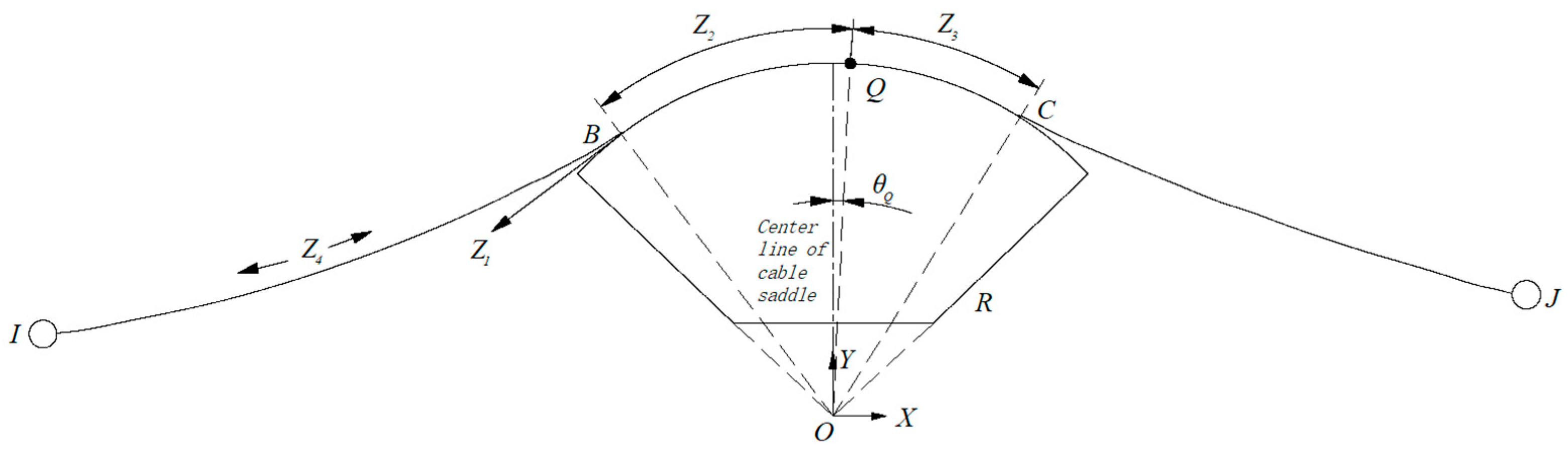
2.2. Determination of Friction

The calculation model of the cable saddle is shown in Figure 5. The coordinate system XOY is established with the center O of the groove in the cable saddle as the origin. In practical engineering, the main cable of the cable saddle section is not allowed to be completely separated from the saddle. Generally, the main cable and the cable saddle are fixed near the center line of the cable saddle. This paper calls it the fixed point of the cable saddle, expressed in Q, as the known point.
For the convenience of calculation, the independent variable vectors as shown in Figure 5 are established, Z = [Z1, Z2, Z3, Z4]. Z1 is the main cable tension T1 of the left main cable at the tangent point (left tangent point B) on the cable saddle. Z2 is the angle of fixed-point Q turns around from the origin O to the left tangent B along the arc anticlockwise. Z3 is the angle of the fixed-point Q turns around from the origin O to the right tangent C along the arc. Z4 is the unstressed length of main cable between point I and B. I and J are the nodes. The coordinates of the left tangent point B can be expressed by the fixed point Q of the cable saddle as
x B = R sin ( Z 2 θ Q )
y B = R cos ( Z 2 θ Q )
Similarly, the coordinates of the right tangent point C are
x C = R sin ( Z 3 + θ Q )
y C = R cos ( Z 3 + θ Q )
The length of the cable segment from the left and right tangent point to the fixed point of the saddle is
s 1 = R ( Z 2 θ Q )
s 2 = R ( Z 3 + θ Q )
According to Hooke’s law, the friction between the cable saddle and main cable is considered. From Equations (3)–(11), the friction f between main cable and saddle is calculated as
f = Z 1 μ ( Z 2 + Z 3 ) [ 1 e μ ( Z 2 + Z 3 ) ]
In the formula, x B and y B are the horizontal and vertical coordinates of the left tangent point B, respectively.   x C and y C are the horizontal and vertical coordinates of the right tangent point C, respectively.   θ Q is the angle between the fixed point Q and the center line of the saddle. R is the arc radius of the cable saddle.

3. Calculation of Cable Saddle Position

3.1. Basic Assumptions

(1)
The main cable is perfectly flexible and can neither be compressed nor bent.
(2)
The material of the main cable conforms to Hooke’s law, and its stress–strain relationship is linear.
(3)
The cross-section area of the main cable changes little under the external load, and the influence of the small change is ignored in the calculation.

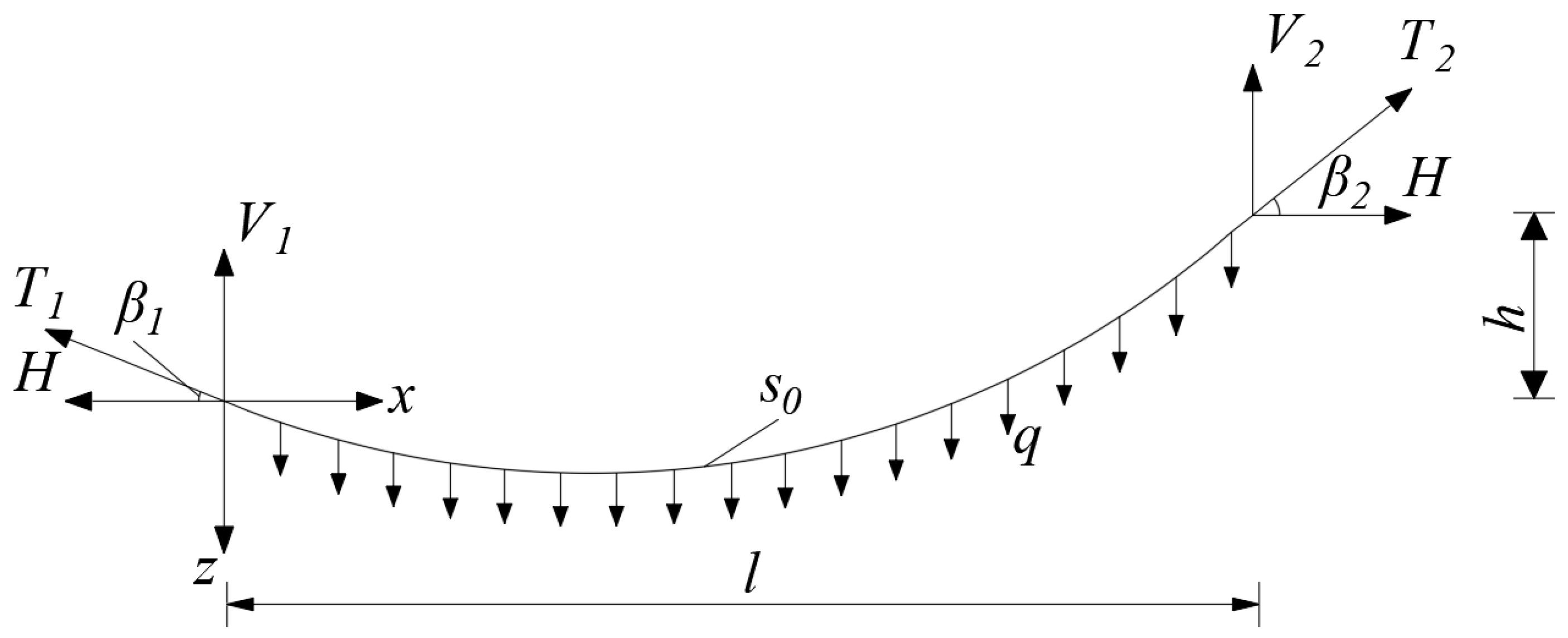
3.2. Basic Formula of Cable Element Expressed by Cable End Force

Based on the basic assumption, the main cable can be simulated by an elastic catenary with uniformly distributed dead load along its unstressed length, as shown in Figure 6. The self-weight uniform load of the cable is q, and the none-stressed length is S 0 , the tensile stiffness is EA, the span between two fulcrum is l, the height difference is h, and the horizontal tension is H. The vertical reaction force at the left end of the strand is V1. The angle between cable force and horizontal direction is β1. The vertical reaction force at the right end of the strand is V2 = qS0V1. The angle between cable force and horizontal direction is β2. Then, the curve expression satisfying the boundary conditions is as follows:
l = H S 0 E A + H q [ ln ( V 1 + H 2 + V 1 2 ) ln ( V 1 q S 0 + ( V 1 q S 0 ) 2 + H 2 ) ]
h = 2 V 1 S 0 q S 0 2 2 E A + 1 q [ H 2 + V 1 2 ( V 1 q S 0 ) 2 + H 2 ]

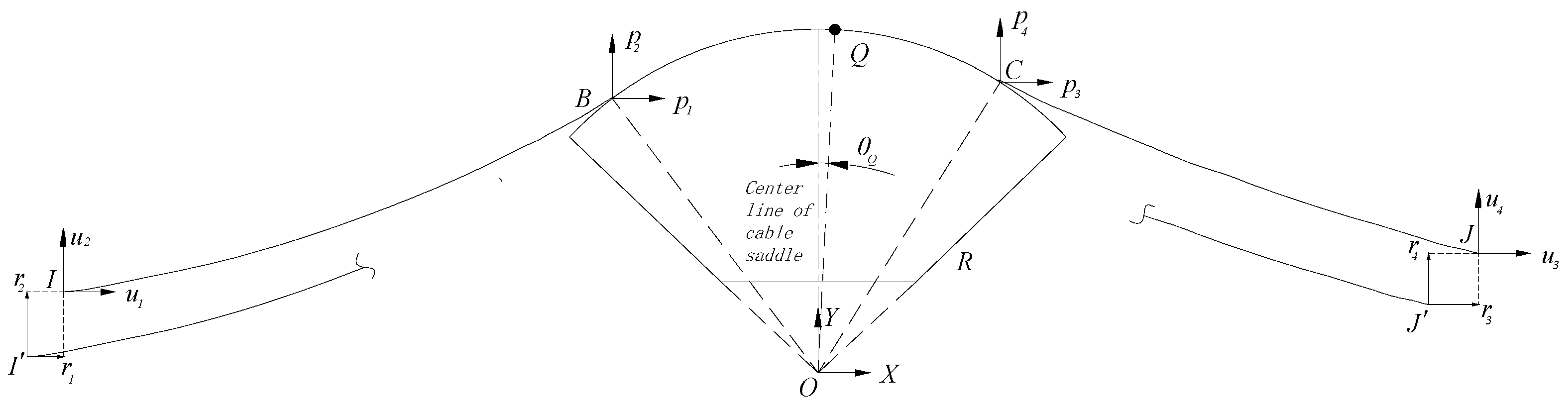
3.3. Determination of Cable Saddle Position

For a section of the main cable unit placed on the cable saddle, when it is in equilibrium, the left node is I and the right node is J. Its position can be uniquely determined by a specific value of fixed-point Q and independent variable Z. When an initial position of the main cable unit is given; that is, an initial independent variable Z is given, the left node is I′, and the right node is J′, as shown in Figure 7. The horizontal and vertical deviations of node I′ and I are r 1 and r 2 , respectively, and the horizontal and vertical deviations of nodes J′ and J are r 3 and r 4 , respectively. In order to facilitate an iterative solution, the deviation r 1 r 4 is composed of deviation vector r.
Since point Q is a fixed point, when the positions of point I and point J change, the tangent points B and C of the suspension cable and cable saddle will also change. According to the tangent point coordinates and friction relations expressed by the fixed point Q of the cable saddle [Equations (6)–(12)] and the analytic formulas of the horizontal and vertical projection length of the elastic catenary [Equations (13) and (14)], the components of the deviation vector r is obtained.
r 1 = x I { R sin ( Z 2 θ Q ) + p 1 . [ 1 q ln ( t B p 2 t I + u 2 ) L 1 E A ] }
r 2 = y I [ R cos ( Z 2 θ Q ) t I t B q . ( t I + t B 2 E A + 1 ) ]
r 3 = x J { R sin ( Z 3 + θ Q ) } + p 3 [ 1 q . ln ( t C p 4 t J + u 4 ) L 2 E A ) ]
r 4 = y J { R cos ( Z 3 + θ Q ) t J ( t C + f ) q . [ t J + ( t C + f ) 2 E A + 1 ] }
From the horizontal force of the main cable and context relation
t B = Z 1
t c = Z 1 cos ( Z 2 θ Q ) cos ( Z 3 + θ Q ) + f
u 1 , u 2 , u 3 and u 4 are the corresponding node forces of node I and J, respectively.   p 1 , p 2 , p 3 and p 4 are the internal forces corresponding to tangent points B and C, respectively.   t B is the main cable tension at the left tangent point B; t c is the main cable tension at the right tangent point C.   x i and y i are the horizontal and vertical coordinates of node I, respectively; x j and y j are the horizontal and vertical coordinates of node J, respectively; L 1 is the unstressed length between I and B of the main cable of the left span (i.e., Z 4 ); L 2 is the unstressed length between C and J of main cable of right span.
According to Newton’s iterative method, a small increment in the independent variable Δ Z produces a small increment in the deviation Δ r , then   Δ r can be approximately expressed by the following formula
Δ r j Δ Z
J is the Jacobian matrix of order 4. The element j i j = r i / Z j , I, J take 1, 2, 3, 4, respectively.
The increment in the independent variable that reduces the deviation can be expressed as
Δ Z j 1 ( r )
Using the Newton iterative method, until the deviation is less than the expected limit, the cable saddle element can be considered to be in equilibrium. The tangent stiffness matrix of the cable saddle element is derived. When the node produces small displacement, in order to maintain the balance, the node will also produce the corresponding small node force. According to Hooke’s law
Δ u k Δ x
k is the tangent stiffness matrix of the fourth order element. The elements k i j = f i / x j , i, j = 1, 2, 3, 4, f i are nodal forces.   Δ x is the node coordinate increment; Δ u is the increment of nodal force to keep balance.
The increment of joint force Δ u can be expressed by the independent variable Z as
u 1 = Z 1 cos ( Z 2 θ Q )
u 2 = q L 1 Z 1 sin ( Z 2 θ Q )
u 3 = [ Z 1 cos ( Z 2 θ Q ) cos ( Z 3 + θ Q ) + f ] cos ( Z 3 + θ Q )
u 4 = q L 2 [ Z 1 cos ( Z 2 θ Q ) cos ( Z 3 + θ Q ) + f ] · sin ( Z 3 + θ Q )
The relationship between node force increment   Δ u and independent variable Z can be expressed as
Δ u = b Δ Z
B is the process variable, and its element b i j = u i / Z j , i and j are 1, 2, 3 and 4, respectively, which can be determined by Equations (24)–(27).
According to Equations (15)–(18), the relationship between Δ r and Δ x is as follows
Δ r = a Δ x
a = diag (1, 1, 1, 1) is the fourth order unit matrix
By substituting Equations (21), (28) and (29) into Equation (23), the tangent stiffness matrix of the cable saddle element can be obtained as:
k = b j 1 a

4. Exact Solution of Catenary Strand Shape Considering Change in Tangent Point

The pre-deflection of the cable saddle is determined according to the principle that the non-stress length between the two control points of cable saddle is invariable. The tangent point position of the cable strand in the saddle groove is iterated to make the force inclination angle of the cable end coincide with the angle of the tangent point of the cable saddle, and then the tangent point position is determined. Then, according to the geometric relationship between the tangent point and the saddle control point and the equilibrium equation of the suspension segment, the height of the strand at any position can be determined.
According to the principle that the non-stress length S 0 between the control points of two saddles is invariable, the strand between two adjacent saddles is divided into three sections. The length of the cable segment between saddle control point m 1 and tangent point TP1 is S 01 , the length of the freely suspended cable segment between tangent point TP1 and tangent point TP2 is S 02 , and the length of the cable segment between tangent point TP2 and saddle control point m 2 is S 03 . Assuming that the stressed length of S 01 and S 03 is equal to the non-stressed length (through calculation, the difference between the empty cable state is very small, and the error can be ignored), then, S 0 = S 01 + S 02 + S 03 . For the freely suspended strand S 02 between the adjacent tangent points, when the horizontal distance l, height difference h and non-stressed cable length S 02 between two end points are determined, the strand shape is unique and satisfies the catenary equations composed of formulae (31) and (32). The sectional calculation diagram of the tangent point of the cable strand is shown in Figure 8. In the figure, α is the included angle between the left cable saddle and the horizontal axis, and θ1 and θ2 are the included angle between the line passing through the arc center and tangent point of the cable saddle and the cable saddle axis, respectively. By iterating the length of S 01 and S 02 the tangent point position is corrected. When the tangent angle at the tangent point of the saddle is consistent with the force inclination angle at the end of the strand, the tangent point position is determined. Then, according to the catenary formula, the elevation of cable strand at any position can be determined.
For the free suspension cable, as shown in Figure 6, the rectangular coordinate system is established with the left end point as the origin. As shown in Figure 8, the equation of the suspension cable is as follows:
z = 1 c c h c x + a + b
c = −q/H, a and b are integral constants, which are related to the boundary conditions of suspension cables.
In the coordinate system shown in Figure 8, x = 0 and z = 0 are introduced into Equation (31) to obtain the following result:
b = 1 c c h a
Taking x = L, z = h into Equation (31), we obtain:
h = 1 c c h ( c l + a ) 1 c c h a
The result of transformation (33) is as follows:
h c = 2 s h ( c l 2 + a ) s h ( c l 2 )
a = s h 1 [ h c 2 s h ( c l 2 ) ] c l 2
So:
1 c c h ( c x + ( s h 1 [ h c 2 s h ( c l 2 ) ] c l 2 ) ) 1 c c h ( s h 1 [ h c 2 s h ( c l 2 ) ] c l 2 )
The specific calculation is as follows: ① Taking the position of tangent point of the completed suspension bridge and S01, S03 as initial values, S02, h, l are calculated; ② S02, h, l and q are introduced into the nonlinear Equations (13) and (14) to iteratively solve the cable end forces H and V1, so as to obtain the angle between the tangent line and the horizontal. Comparing β1 and 90°-α-θ1, β2 and θ2, respectively, if the difference is greater than 10−3, then correct θ1, θ2 and S01, S03. Returning to step 1 and recalculating, until the difference between β1 and 90°-α-θ1, β2 and θ2 is less than 10−3, this time, TP1 and TP2 are the tangent points of the strand and saddle in the current state. After the tangent point position is determined, the coordinates of any point of the datum strand can be determined according to Equation (36).
The calculation process of the accurate solution method for the datum strand geometric shape is shown in Figure 9. According to the calculation flow, MATLAB language can be used to write the program of exact solution of the cable strand line.

5. Example Verification

The Shanxi Juhe bridge is a three-tower self-anchored suspension bridge. The span arrangement is 50 + 80 + 168 + 168 + 80 + 50 = 596 m. The elastic modulus of the main cable is 205 GPa, the cross-sectional area of the main cable is 0.10172 m2, the saddle radius is 3.5 m, and the unit length weight of the main cable is 8.19 kN/m. The coordinates of the left marking point of the main cable are (−240.073, −38.016), the coordinates of the fixed point of the cable saddle are (−168.470, 0.018), and the coordinates of the right marking point of the main cable are (−84.224, −32.435). The middle point elevation of the main cable side span is 472.096 m, and that of the middle span is 464.903 m. The middle point position parameters are shown in Table 1. MIDAS and ABAQUS are also used to compare with the method in this paper, which shows the reliability of the results.
In order to compare with the method in this paper, finite element models are established using MIDAS and ABAQUS.
As shown in Figure 10, MIDAS is used to establish the full bridge finite element model of the self-anchored suspension bridge, in which the main cable and sling are modeled by cable element, the rest are modeled by beam element, and the main cable and the main tower are connected by a rigid arm. As shown in Figure 11, ABAQUS was used to establish the local finite element model of the bridge tower, cable saddle and main cable. The bridge tower and cable saddle are simulated by solid elements, and the main cable is simulated by truss elements. The bottom of the tower root is fixed, and the bottom surface of the cable saddle is bound to the tower. The main cable is equivalent to one and the contact relationship with the arc surface of the cable saddle is established. The normal direction is set as hard contact, and the tangential friction coefficient is taken as 0.24. The actual cable end force of the whole bridge model is extracted to act on the local model, and the tangent point coordinates of the main cable when considering friction are obtained. Then, the tangent coordinates are input into the full bridge model to obtain the main cable shape and mid span vertical coordinates under the consideration of friction. The results with and without friction are shown in Table 1.
In this paper, the example is calculated by MATLAB program, and the results show that it is accurate and reliable and can converge after three or four iterations (the allowable deviation is less than 1.0 × 10⁻⁶ m). Considering the influence of friction, the main cable shape will be slightly affected.

6. Conclusions

(1)
Based on Euler formula and Hooke’s law, the formula for calculating the friction resistance of the main cable and cable saddle, considering the position change in the cable saddle, is derived. Based on the elastic catenary theory, a deviation algorithm considering the friction between the main cable and saddle is proposed by introducing a group of independent variables. The algorithm has fast convergence speed and high calculation accuracy.
(2)
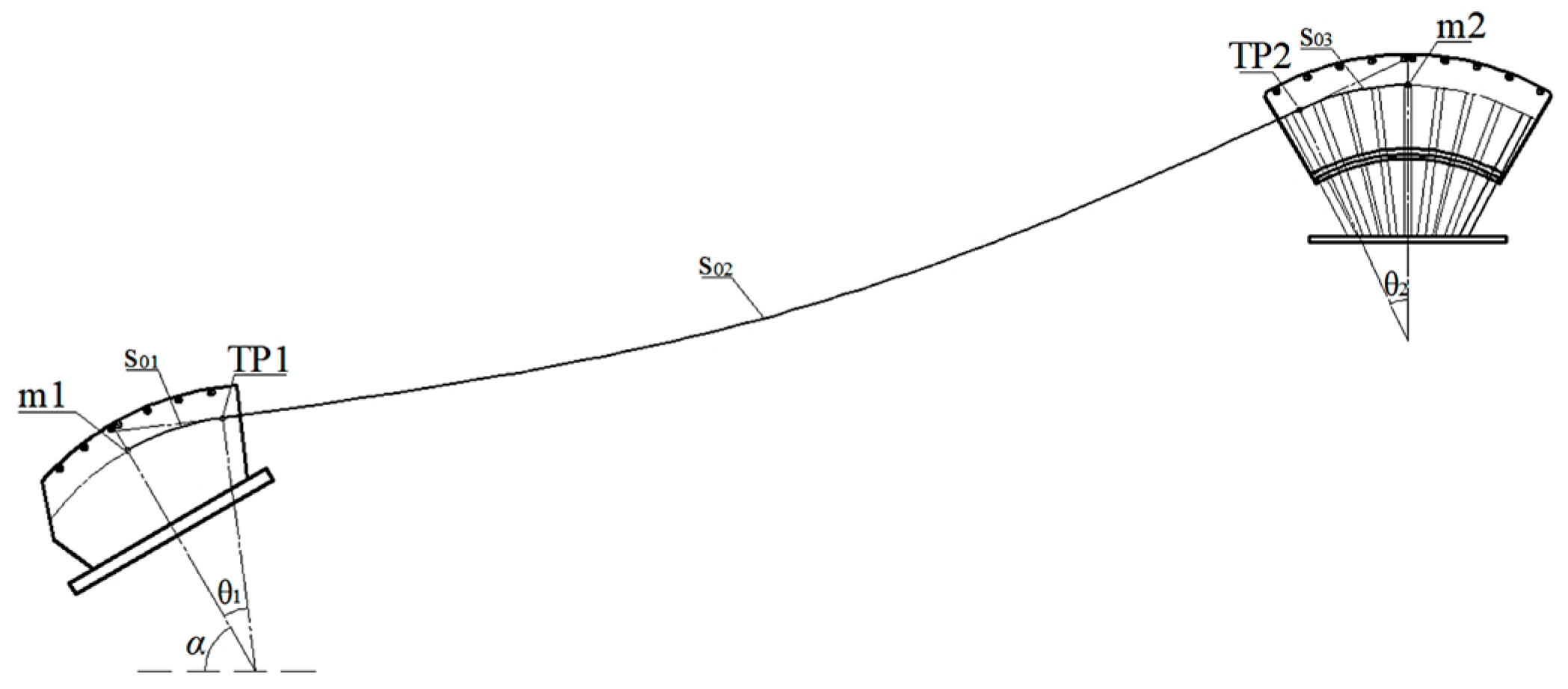
On the condition that the pre-deflection of the cable saddle is determined, the tangent point of the cable strand in the saddle groove is obtained by iterative calculation. Then, according to the calculation model of the catenary strand, the coordinates of any point of strand are determined, and the strand shape, considering the influence of friction, can be obtained.
(3)
The parameter analysis of the cable strand line and friction coefficient shows that the elevation of cable strand changes linearly with the linear change in friction resistance, and the change amount is small (the influence is millimeter level), and the influence of friction resistance can be ignored in a simplified calculation.
(4)
This algorithm is suitable for the accurate calculation of the saddle position of a plane cable plane suspension bridge. The accurate calculation of the saddle position of a space cable plane suspension bridge will be the focus of the next stage.

Author Contributions

Conceptualization, X.Z. (Xiangong Zhou); Funding acquisition, X.Z. (Xiaobo Zheng); Methodology, H.H.; Writing—original draft, X.Z. (Xiangong Zhou); Writing—review & editing, Y.C. and Z.L. All authors have read and agreed to the published version of the manuscript.

Funding

The authors gratefully acknowledge the financial support of the Natural Science Foundation of Shaanxi (No. 2022JQ-415).

Institutional Review Board Statement

Not applicable.

Informed Consent Statement

Not applicable.

Data Availability Statement

The data of this study are available from the corresponding author upon request.

Acknowledgments

The help of engineers and technicians in the Key Laboratory of Bridge Detection Reinforcement Technology Ministry of Communications of Chang’an University is highly appreciated. These supports are gratefully acknowledged.

Conflicts of Interest

The authors declare no conflict of interest.

References

  1. He, S.H. Theory and Calculation Method of Bridge Structures; China Communications Press: Beijing, China, 2017. [Google Scholar]
  2. Zhang, W.M.; Li, T.; Shi, L.Y.; Liu, Z.; Qian, K.R. An iterative calculation method for hanger tensions and the cable shape of a suspension bridge based on the catenary theory and finite element method. Adv. Struct. Eng. 2019, 22, 1566–1578. [Google Scholar] [CrossRef]
  3. Wang, S.R.; Zhou, Z.X.; Wen, D.; Huang, Y.Y. New Method for Calculating the Preoffsetting Value of the Saddle on Suspension Bridges Considering the Influence of More Parameters. J. Bridge Eng. 2016, 21, 9. [Google Scholar] [CrossRef]
  4. Jia, L.J.; Lin, Z.B.; Xiao, R.C.; Jiang, Y. Parameter effects on the mechanical performance of triple-tower four-span suspension bridges. Adv. Struct. Eng. 2018, 21, 256–269. [Google Scholar] [CrossRef]
  5. Jia, L.J.; Zhang, C.; Jiang, Y.; Cheng, J.; Xiao, R.C. Simplified Calculation Methods for Static Behaviors of Triple-Tower Suspension Bridges and Parametric Study. Int. J. Steel Struct. 2018, 18, 685–698. [Google Scholar] [CrossRef]
  6. Ruan, X.; Zhou, J.Y.; Caprani, C.C. Safety Assessment of the Antisliding between the Main Cable and Middle Saddle of a Three-Pylon Suspension Bridge Considering Traffic Load Modeling. J. Bridge Eng. 2016, 21, 10. [Google Scholar] [CrossRef]
  7. Pevrot, A.H.; Goulois, A.M. Analysis of cable structures. Comput. Struct. 1979, 10, 805–813. [Google Scholar] [CrossRef]
  8. Luo, X.H. Effect of saddle on cable shape of suspension bridges. J. Highw. Transp. Res. Dev. 2005, 8, 36–39+48. [Google Scholar]
  9. Li, C.X.; Wang, L.; Liu, G.D.; Chen, M.X.; Xiao, Y.G. Separate calculation method on suspension bridge saddle’s position. China J. Highw. Transp. 2005, 1, 67–72. [Google Scholar]
  10. Wang, S.R.; Zhou, Z.X.; Gao, Y.M.; Xu, J. Newton-Raphson algorithm for pre-offsetting of cable saddle on suspension bridge. China J. Highw. Transp. 2016, 29, 82–88. [Google Scholar]
  11. Cheng, J.; Xu, H.; Xu, M.S. Study on midtower longitudinal stiffness of three-tower four-span suspension bridges with steel truss girders. Struct. Eng. Mech. 2020, 73, 641–649. [Google Scholar]
  12. Cheng, Z.Y.; Zhang, Q.H.; Bao, Y.; Jia, D.L.; Bu, Y.Z.; Li, Q. Analytical Models of Frictional Resistance between Cable and Saddle Equipped with Friction Plates for Multispan Suspension Bridges. J. Bridge Eng. 2018, 23, 13. [Google Scholar] [CrossRef]
  13. Han, S.H.; Zhang, Q.H.; Bao, Y.; Cheng, Z.Y.; Jia, D.L.; Bu, Y.Z. Frictional Resistance Between Main Cable and Saddle for Suspension Bridges. II: Interlayer Slip of Strands. J. Bridge Eng. 2020, 25, 04020043. [Google Scholar] [CrossRef]
  14. Niu, Y.W.; Rong, S.; Qu, X.X.; Zhao, Y.; Huang, P.M. Simulation of Friction Between Cable and Subwire Tube in Saddle Type Anchorage of Low-Tower Cable-Stayed Bridge. J. Balk. Tribol. Assoc. 2015, 21, 1087–1099. [Google Scholar]
  15. Wang, B.J.; Li, Q.B.; Liu, T.Y.; Peng, W.B. Analysis of Cable under Dynamic Contact and Large Deformation. Ksce J. Civ. Eng. 2019, 23, 1626–1635. [Google Scholar] [CrossRef]
  16. Wang, L.; Shen, R.L.; Ma, N.J.; Zhang, S.H.; Gu, L.X.; Wang, R.H. Discrete analytical model for lateral mechanical behavior of cable-saddle system in suspension bridges. Eng. Struct. 2020, 221, 13. [Google Scholar] [CrossRef]
  17. Wang, L.; Shen, R.L.; Wang, C.J.; Zhang, S.H.; Wang, Y. Theoretical and Experimental Studies of the Antislip Capacity between Cable and Saddle Equipped with Horizontal Friction Plates. J. Bridge Eng. 2019, 24, 15. [Google Scholar] [CrossRef]
  18. Zhang, Q.H.; Cheng, Z.Y.; Cui, C.; Bao, Y.; He, J.; Li, Q. Analytical Model for Frictional Resistance between Cable and Saddle of Suspension Bridges Equipped with Vertical Friction Plates. J. Bridge Eng. 2017, 22, 12. [Google Scholar] [CrossRef]
  19. Zhang, Q.H.; Guo, H.L.; Bao, Y.; Cheng, Z.Y.; Jia, D.L. Antislip Safety of Double-Cable Multispan Suspension Bridges with Innovative Saddles. J. Bridge Eng. 2020, 25, 12. [Google Scholar] [CrossRef]
  20. Zhang, Q.H.; Han, S.H.; Bao, Y.; Cheng, Z.Y.; Jia, D.L.; Bu, Y.Z. Frictional Resistance between Main Cable and Saddle for Suspension Bridges. I: Friction Characteristic of Single Strand. J. Bridge Eng. 2020, 25, 04020042. [Google Scholar] [CrossRef]
  21. Zhang, Q.H.; Kang, J.P.; Bao, Y.; Cheng, Z.Y.; Jia, D.L.; Bu, Y.Z. Numerical study on cable-saddle frictional resistance of multispan suspension bridges. J. Constr. Steel. Res. 2018, 150, 51–59. [Google Scholar] [CrossRef]
  22. He, S.H.; Chen, Y.H.; Li, Y. Exact algorithm for cable saddle of suspension bridge influences by frictional resistance. J. Chang. Univ. (Nat. Sci. Ed.) 2019, 39, 57–64. [Google Scholar]
  23. Li, T.; Liu, Z.; Zhang, W. Analysis of suspension bridges in construction and completed status considering the pylon saddles. Eur. J. Environ. Civ. Eng. 2020, 26, 4280–4295. [Google Scholar] [CrossRef]
  24. Zhang, W.M.; Tian, G.M.; Yang, C.Y.; Liu, Z. Analytical methods for determining the cable configuration and construction parameters of a suspension bridge. Struct. Eng. Mech. 2019, 71, 603–625. [Google Scholar]
  25. Zhang, W.M.; Tian, G.M.; Liu, Z. Analytical Study of Uniform Thermal Effects on Cable Configuration of a Suspension Bridge during Construction. J. Bridge Eng. 2019, 24, 18. [Google Scholar] [CrossRef]
  26. Zhang, W.M.; Yang, C.Y.; Tian, G.M.; Liu, Z. Analytical Assessment of Main Cable Shape for Three-Pylon Suspension Bridge with Unequal Main-Span Lengths: Thermal Effect Consideration. J. Bridge Eng. 2020, 25, 14. [Google Scholar] [CrossRef]
  27. Zhang, W.M.; Yang, C.Y.; Chang, J.Q. Cable Shape and Construction Parameters of Triple-Tower Double-Cable Suspension Bridge with Two Asymmetrical Main Spans. J. Bridge Eng. 2021, 26, 20. [Google Scholar] [CrossRef]
  28. Zhang, W.M.; Yang, C.Y.; Wang, Z.W.; Liu, Z. An analytical algorithm for reasonable central tower stiffness in the three-tower suspension bridge with unequal-length main spans. Eng. Struct. 2019, 199, 13. [Google Scholar] [CrossRef]
  29. Liang, Z.L.; Song, Y.F.; Yan, L. Study on positioning and adjusting method of datum strands for suspension bridge. J. Highw. Transp. Res. Dev. 2019, 36, 84–90. [Google Scholar]
Figure 1. Cross-section of datum cable.
Applsci 12 07565 g001
Figure 2. Perspective view of cable saddle.
Applsci 12 07565 g002
Figure 3. Schematic of force on cable-bearing trough.
Applsci 12 07565 g003
Figure 4. Schematic diagram of contact section between main cable and cable saddle.
Applsci 12 07565 g004
Figure 5. Calculation model of cable saddle.
Applsci 12 07565 g005
Figure 6. Catenary cable calculation model diagram.
Applsci 12 07565 g006
Figure 7. Schematic diagram of cable saddle force and deviation.
Applsci 12 07565 g007
Figure 8. Calculation diagram of tangent point segment of cable strand.
Applsci 12 07565 g008
Figure 9. Calculation process of cable strand geometric shape considering the change in tangent point.
Applsci 12 07565 g009
Figure 10. Full bridge finite element model.
Applsci 12 07565 g010
Figure 11. Partial details of main cable and saddle.
Applsci 12 07565 g011
Table 1. Comparison of Calculation Results of Free Cable Shape (Unit: m).
Position of Middle PointFriction Is Not ConsideredFriction Is Considered
The method in this paper464.902 69464.903 43
Calculated by finite element464.900 25464.901 12
Publisher’s Note: MDPI stays neutral with regard to jurisdictional claims in published maps and institutional affiliations.

