
Research on the Decoupling of the Parallel Vehicle Tilting and Steering Mechanism


Abstract
:Featured Application
Abstract
1. Introduction
- A parallel mechanism is proposed. It consists of a spatial steering mechanism and a tilting mechanism in parallel.
- A mathematical model of the parallel mechanism including the wheel alignment parameters has been established. This model is a kinematic model. The decoupling conditions of the parallel mechanism (DCPM) have been solved. A decoupling method is proposed that is based on the model.
- The parameters of the parallel mechanism have been obtained by the use of the mathematical model. These parameters consider both the DCPM and the ASC.
- A prototype has been produced according to the parameters for an experiment. It has been proven by the experiment that the method can reduce the influence of the vehicle’s tilting on the steering angle of the wheels. The prototype is able to ensure that the steering angles of the wheels on both sides satisfy the ASC effectively.
2. Mechanism, Model, and Decoupling Method
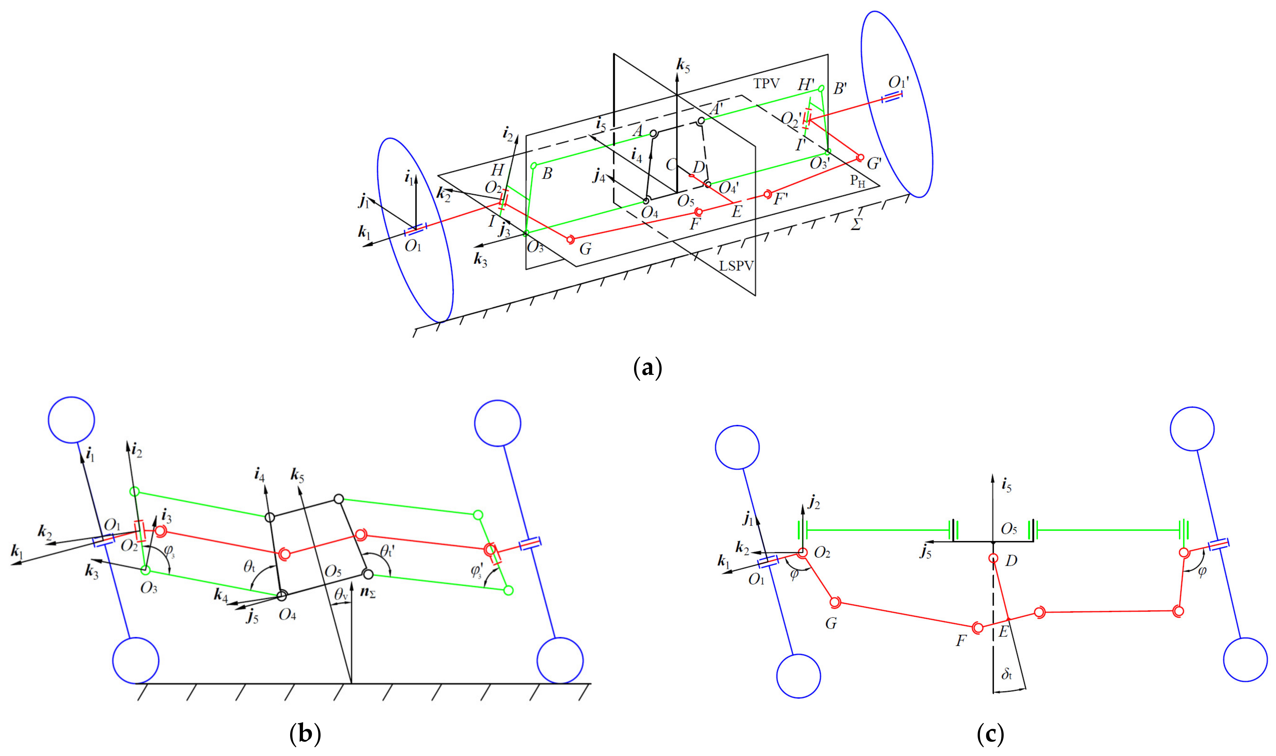
2.1. The Parallel Mechanism
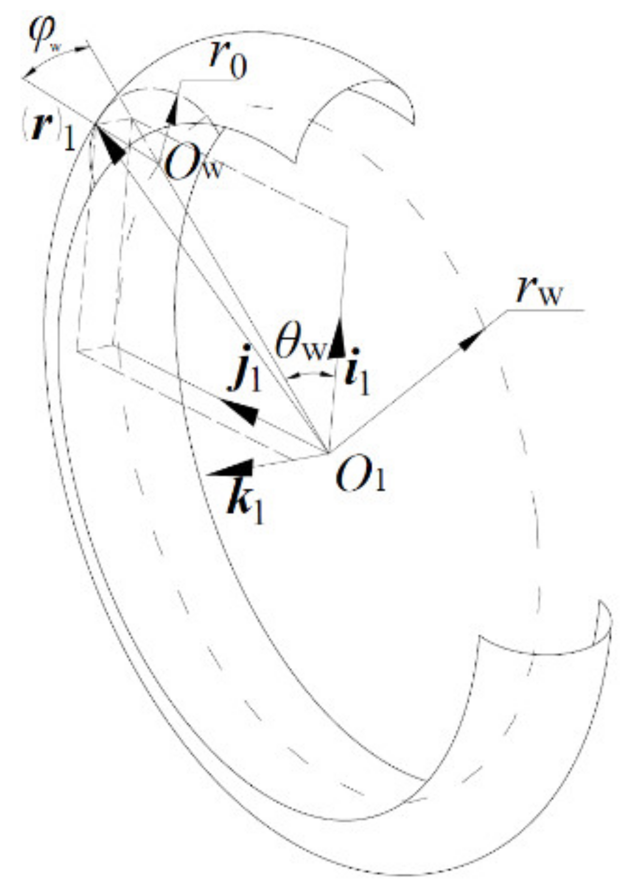
2.2. Mathematical Model
2.3. The DCPM and the ASC
3. Simulation and Experiment
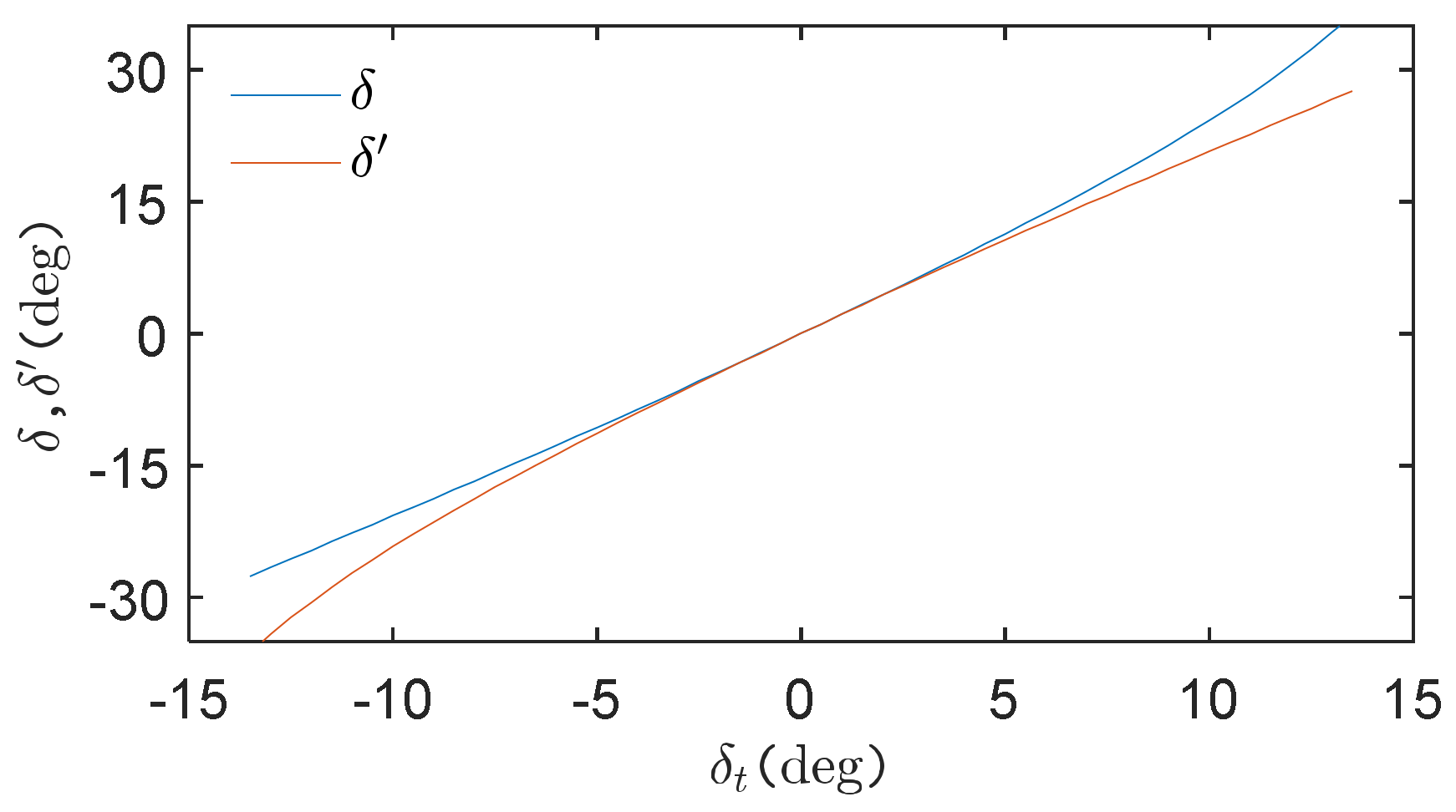
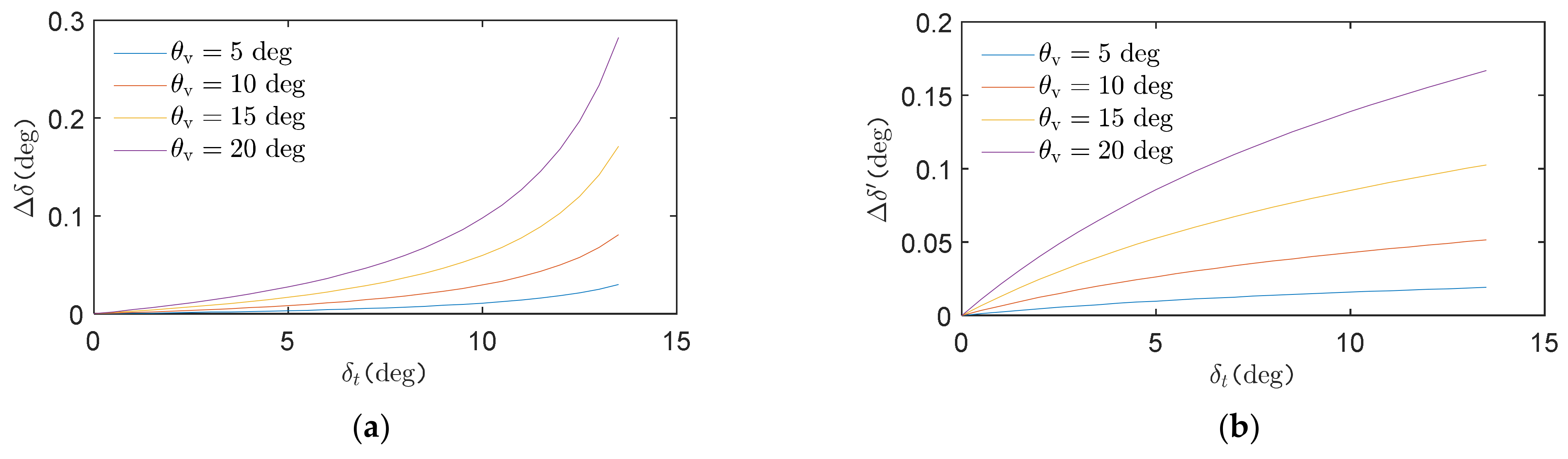
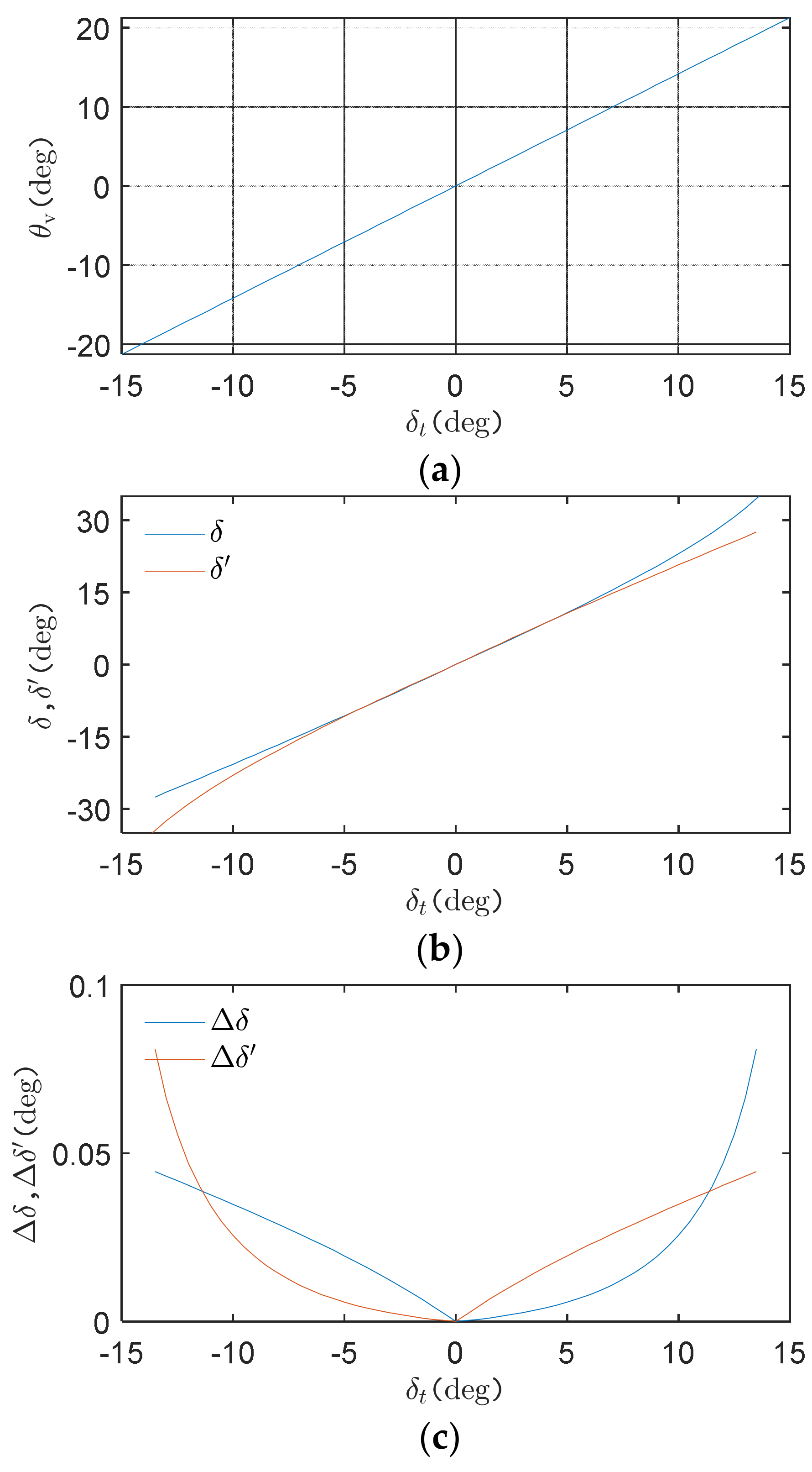
3.1. Simulation
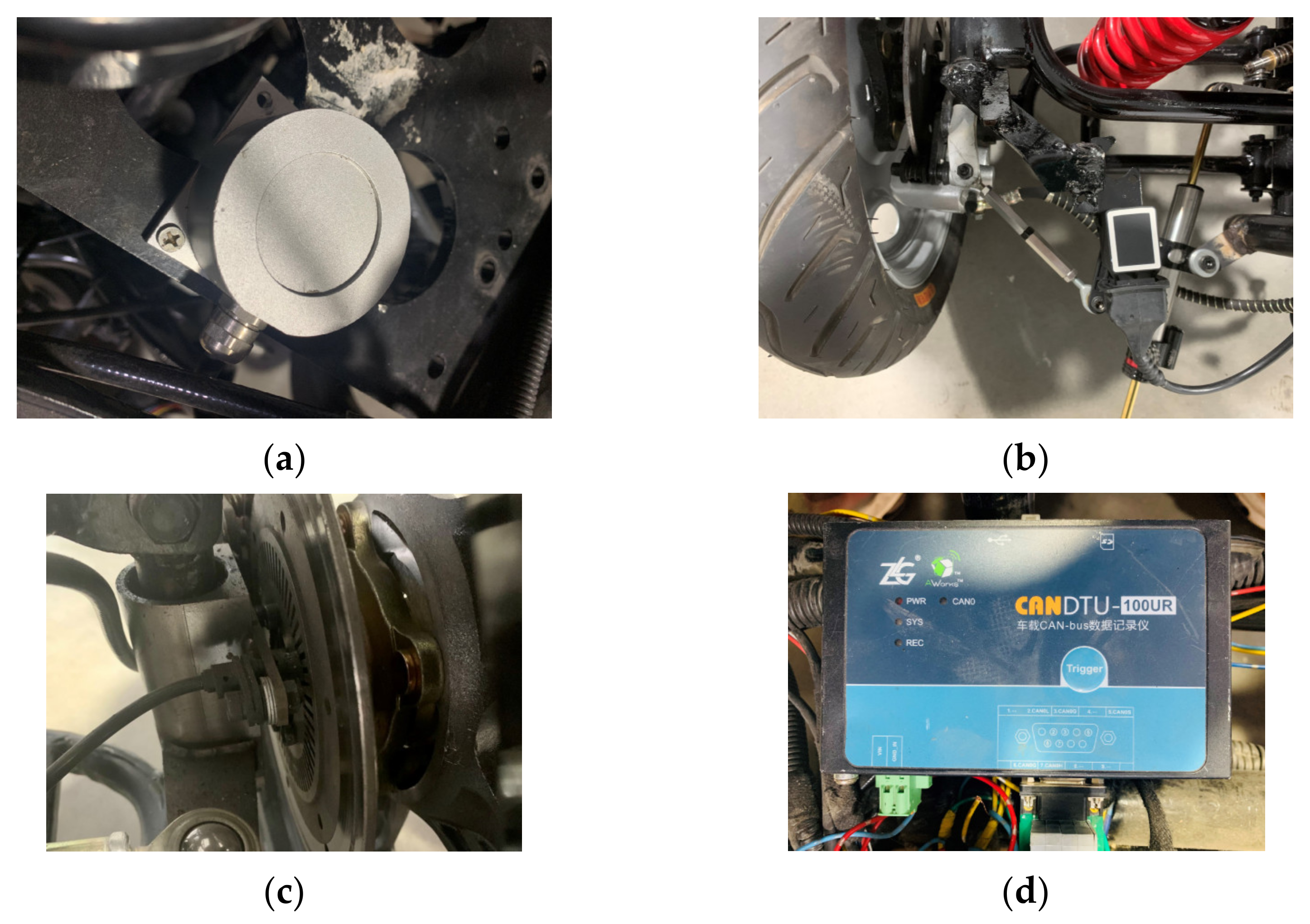
3.2. Experiment
4. Discussion
5. Conclusions
- This paper proposes a tilting and steering parallel mechanism. The proposed parallel mechanism consists of a spatial steering mechanism and a tilting mechanism. The parallel mechanism can be used as the suspension for ATV.
- This study establishes a mathematical model that may be used to analyze the DCPM. The model is infinitely rigid, ignoring the effects of vehicle dynamics. This model is a kinematic model. A decoupling method has been proposed that is based on the model.
- The effectiveness of the decoupling method has been proven by an experiment on a prototype. The low-speed (25 km/h) experiments verified the kinematics of the proposed parallel mechanism. The prototype can reduce the influence of vehicle tilting on the steering angle of the outer and inner wheels by up to 0.64% and 0.78%, respectively. The SGCR of the prototype is between 1.198 and 0.961.
- The proposed parallel mechanism that is based on the proposed decoupling method simultaneously achieves the following purposes: a) ignoring the effects of the nonlinear change of the tires, (b) decoupling the tilting and steering parallel mechanism of the vehicle, and (c) making the wheels on both sides of the vehicle satisfy the ASC.
6. Patents
Author Contributions
Funding
Institutional Review Board Statement
Informed Consent Statement
Data Availability Statement
Acknowledgments
Conflicts of Interest
References
- Navikas, D.; Pitrėnas, A. Determination and Evaluation of a Three-Wheeled Tilting Vehicle Prototype’s Dynamic Characteristics. Appl. Sci. 2022, 12, 5121. [Google Scholar] [CrossRef]
- Haraguchi, T.; Kageyama, I.; Kaneko, T. Study of Personal Mobility Vehicle (PMV) with Active Inward Tilting Mechanism on Obstacle Avoidance and Energy Efficiency. Appl. Sci. 2019, 9, 4737. [Google Scholar] [CrossRef] [Green Version]
- Haraguchi, T.; Kageyama, I.; Kaneko, T. Inner Wheel Lifting Characteristics of Tilting Type Personal Mobility Vehicle by Sudden Steering Input. Jido Sha Gijutsukai Ronbunshu 2019, 50, 96–101. [Google Scholar] [CrossRef]
- Kashem, S.; Saravana, K. Comprehensive study on suspension system and tilting vehicle. Aust. J. Basic Appl. Sci. 2015, 9, 46–53. [Google Scholar]
- Li, H.; Gao, R.; Li, X.; Zhang, J.; Wang, Y.; Wei, W. Vehicle Tilting Control Method. Patent No. CN 111231935 A, 13 January 2020. [Google Scholar]
- Karamuk, M.; Alankus, O.B. Development and Experimental Implementation of Active Tilt Control System Using a Servo Motor Actuator for Narrow Tilting Electric Vehicle. Energies 2022, 15, 1996. [Google Scholar] [CrossRef]
- Liu, P.; Li, X.; Gao, R.; Li, H.; Wei, W.; Wang, Y. Design and experiment of tilt-driving mechanism for the vehicle. J. Jilin Univ. 2022. [Google Scholar] [CrossRef]
- Haraguchi, T.; Kaneko, T.; Kageyama, I. A Study of Steer Characteristics of Personal Mobility Vehicle (PMV) with Inward Tilting Mechanism. Trans. Soc. Automot. Eng. Jpn. 2022, 53, 58–64. [Google Scholar]
- Matsuda, M.; Kageyama, I.; Kuritagawa, Y.; Haraguchi, T.; Kaneko, T.; Kobayashi, M.; Murayama, T. Study on Driving Behavior Considered Vehicle Characteristics of Personal Mobility Vehicle with Lean Mechanism. In Proceedings of the Japan Society of Mechanical Engineers, Transportation and Logistics Conference, Tokyo, Japan, 21 January 2019; pp. 96–101. [Google Scholar]
- Liu, P.; Ke, C.; Gao, R.; Li, H.; Wei, W.; Wang, Y. Design and Test of Active Roll Vehicle. Automot. Eng. 2020, 42, 1552–1557 + 1584. [Google Scholar] [CrossRef]
- Wang, Y.; Wei, W.; Li, H. Vehicle Steering Tilt Combined Mechanism and Active Tilting Vehicle Using the Mechanism. Patent No. CN110386216A, 29 October 2019. [Google Scholar]
- Shino, K. Active Tilting Vehicle. Patent No. CN110386216A, 22 September 2020. [Google Scholar]
- Cho, Y.H.; Kim, J.-H. Design of Optimal Four-Wheel Steering System. Veh. Syst. Dyn. 1995, 24, 661–682. [Google Scholar] [CrossRef]
- Sun, Q.H.; Dong, E.G.; Zhang, L.; Gao, S.R. Parameters analysis and optimal design of four-bar steering mechanism. J. Liaoning Tech. Univ. 2007, 26, 278–280. [Google Scholar]
- Bian, X.L.; Song, B.A.; Becker, W. The optimization design of the McPherson strut and steering mechanism for automobiles. Forsch. Im Ing. 2003, 68, 60–65. [Google Scholar] [CrossRef]
- Zhao, J.-S.; Liu, X.; Feng, Z.-J.; Dai, J.S. Design of an Ackermann-type steering mechanism. Proc. Inst. Mech. Eng. Part C J. Mech. Eng. Sci. 2013, 227, 2549–2562. [Google Scholar] [CrossRef]
- Shen, H.; Wu, C.; Chablat, D.; Wu, G.; Yang, T.-L. Topological design of an asymmetric 3-translational parallel mechanism with zero coupling degree and motion decoupling. In Proceedings of the ASME 2018 International Design Engineering Technical Conferences & Computers and Information in Engineering Conference, Quebec City, QC, Canada, 26–29 August 2018; pp. 7–38. [Google Scholar]
- Shen, H.; Chablat, D.; Zeng, B.; Li, J.; Wu, G.; Yang, T.-L. A Translational Three-Degrees-of-Freedom Parallel Mechanism with Partial Motion Decoupling and Analytic Direct Kinematics. J. Mech. Robot. 2020, 12, 021112–021119. [Google Scholar] [CrossRef] [Green Version]
- Zeng, D.; Wang, H.; Fan, M.; Wang, J.; Hou, Y. Type Synthesis of Three Degrees of Freedom Rotational Generalized Decoupling Parallel Mechanism. J. Mech. Eng. 2017, 53, 17–24. [Google Scholar] [CrossRef]
- General Administration of Quality Supervision, Inspection and Quarantine of the People’s Republic of China. GB/T 2983-2015 Series of Motorcycle Tyres; General Administration of Quality Supervision, Inspection and Quarantine of the People’s Republic of China: Beijing, China, 2015.
- Dong, X.; Li, H.; Wei, W. Theory and Application of Gear Meshing with Double Degrees of Freedom; China Machine Press: Beijing, China, 2011. [Google Scholar]
- Wang, X. Automotive Chassis Design; Tsinghua University Press: Beijing, China, 2014. [Google Scholar]


| AO4, AꞌO4ꞌ, BO3, and BꞌO3ꞌ | AAꞌ and O4O4ꞌ | AB, AꞌBꞌ, O3O4, and O3ꞌO4ꞌ | O1O2 and O1ꞌO2ꞌ |
| 175.0 mm | 150.0 mm | 290.0 mm | 80.0 mm |
| O2I, O2ꞌIꞌ | O5C | O2G, O2ꞌGꞌ | O3I, O3ꞌIꞌ |
| 88.8 mm | 87.5 mm | 10.7 mm | 81.0 mm |
| r0 | rw | ||
| 50.0 mm | 200.0 mm | ||
| φi | φb | φc | φt |
| 7.5 deg | 5.5° | 1.0° | 0.3° |
| Function | Hardware |
|---|---|
| , and fit trajectory. | Inertial measurement unit: VG427C-CAN. |
| Read δt, δ, and δꞌ. | Angle sensor: KD-701. |
| Read v. | Wheel speed sensor: TE-ABS-181. |
| Record the experimental data. | Data logger: CANDTU-100UR. |
| θv = 0 deg | θv = 10 deg | θv = 20 deg | |
|---|---|---|---|
| δꞌ | 0.46% | 0.69% | 0.91% |
| δ | 0.51% | 0.77% | 1.07% |
| δꞌ | δ | Trajectory | ||
|---|---|---|---|---|
| θv = 10 deg | 0.45% | 0.57% | 0.98% | 1.04% |
| θv = 20 deg | 0.64% | 0.78% | 2.49% | 2.09% |
| θv = 0 deg | θv = 10 deg | θv = 20 deg | |
|---|---|---|---|
| Maximum | 1.146 | 1.160 | 1.198 |
| Average | 1.031 | 1.025 | 1.016 |
Publisher’s Note: MDPI stays neutral with regard to jurisdictional claims in published maps and institutional affiliations. |
© 2022 by the authors. Licensee MDPI, Basel, Switzerland. This article is an open access article distributed under the terms and conditions of the Creative Commons Attribution (CC BY) license (https://creativecommons.org/licenses/by/4.0/).
Share and Cite
Gao, R.; Li, H.; Wei, W.; Wang, Y. Research on the Decoupling of the Parallel Vehicle Tilting and Steering Mechanism. Appl. Sci. 2022, 12, 7502. https://doi.org/10.3390/app12157502
Gao R, Li H, Wei W, Wang Y. Research on the Decoupling of the Parallel Vehicle Tilting and Steering Mechanism. Applied Sciences. 2022; 12(15):7502. https://doi.org/10.3390/app12157502
Chicago/Turabian StyleGao, Ruolin, Haitao Li, Wenjun Wei, and Ya Wang. 2022. "Research on the Decoupling of the Parallel Vehicle Tilting and Steering Mechanism" Applied Sciences 12, no. 15: 7502. https://doi.org/10.3390/app12157502
APA StyleGao, R., Li, H., Wei, W., & Wang, Y. (2022). Research on the Decoupling of the Parallel Vehicle Tilting and Steering Mechanism. Applied Sciences, 12(15), 7502. https://doi.org/10.3390/app12157502