Article

Enhanced Adhesion—Efficient Demolding Integration DLP 3D Printing Device

1
College of Mechanical Science and Engineering, Northeast Petroleum University, Daqing 163318, China
2
Ningbo Runyes Medical Instrument Co., Ltd., Ningbo 315300, China
3
Research and Development Center of 3D Printing Material and Technology, Northeast Forestry University, Harbin 150040, China
*
Authors to whom correspondence should be addressed.
Appl. Sci. 2022, 12(15), 7373; https://doi.org/10.3390/app12157373
Submission received: 17 June 2022 / Revised: 11 July 2022 / Accepted: 19 July 2022 / Published: 22 July 2022
(This article belongs to the Section Additive Manufacturing Technologies)

Abstract

:
A novel forming method of enhanced adhesion-efficient demolding integration is proposed to solve the problems of weak adhesion between the initial forming layer and the printing platform as well as the excessive stripping force at the bottom of the liquid tank when the printing platform rises. Therefore, a digital light processing (DLP) 3D printing forming device equipped with a porous replaceable printing platform and a swing mechanism for the liquid tank is manufactured and verified by experiments. The experimental results show that the porous printing platform can enhance the adhesion between the initial forming layer and the printing platform and improve the demolding efficiency of the forming device. In addition, the pull-out design of the printing platform plate reduces the maintenance cost of the forming device. Therefore, the device has a good application prospect.

1. Introduction

Three-dimensional printing, also known as additive manufacturing (AM), is a processing method for creating three-dimensional objects by printing powder layer by layer [1]. Compared with the subtractive manufacturing methods, additive manufacturing technology is a “bottom-up” material accumulation method [2]; its unique processing method has prominent advantages in mass customization and being lightweight. Combined with the data and Internet integration of industry 4.0, it will have higher efficiency, more utility and more eco-friendly production potential [3]. Its principle is the process of slicing the 3D model to obtain the 3D coordinates of the model contour by software and then stacking the slicing layer by layer into the real object [4]. Its molding process can be divided into: Stereo Lithography Apparatus (SLA) [5], Selective Laser Sintering (SLS) [6], Laminated Object Manufacturing (LOM) [7], Fused Deposition Modeling (FDM) [8] and other technologies. Digital light processing (DLP) 3D printing technology belongs to the subdivision of SLA technology [9]. Because DLP 3D printing technology uses a surface light source, compared with other 3D printing technologies, DLP 3D printing technology has the advantages of high efficiency [10], high precision and individualization. Therefore, it is widely used in dentistry [11], jewelry [12] and other precision fields.
DLP 3D printing technology first obtains two-dimensional slice images from a three-dimensional model, and then the projection system is controlled to realize the projection of the images, the mechanical structure is driven to complete printing layer by layer and the model is finally manufactured [13]. Although DLP photocuring formed equipment has been well applied, there are still problems such as weak adhesion of the forming layer and excessive separation force when the printing platform rises [14]. This separation force mainly comes from the adhesion of the cured resin and the vacuum suction caused by the topical negative pressure when the resin is not filled in time as the printing platform rises [15]. In order to reduce the separation force, Huang et al. [16] proposed enhancing the adhesion by means of over-curing, but this would reduce the accuracy and printing speed of the model. The dual-channel method proposed by Pan et al. [17] can also reduce the separation force through the lateral movement of the liquid tank, but it will greatly increase the printing time. A new technology, continuous liquid interface production, was proposed by researchers at the University of North Carolina in 2015 [18]. The technique utilized oxygen polymerization to create a tiny “dead zone” between the solidified layer and the bottom of the tank, significantly reducing the separation force. However, the Teflon film is expensive, limiting the development of the technology. The above methods solved the problems by reducing the separation force; this paper aims to improve the adhesion between the model and the printing platform by changing the mechanical structure and improving the demolding efficiency and success rate of the printing model by combining the structure with the demolding device.
In this work, through the design of the key components of the mechanical movement system, hardware and control system, a DLP 3D printing forming device equipped with a porous printing platform that is easy to be replaced and a swing mechanism for the liquid tank is manufactured. The equipment uses Z-axis slide rail and limit switch as a mechanical motion system, Raspberry PI as the control core, an LED UV light machine as the light source and the expansion board for driving the movement of the stepping motor to achieve the movement and control of DLP 3D printing equipment. The design of the porous printing platform and the swing mechanism can not only enhance the adhesion between the initial forming layer and the printing platform and make forming layer easier to separate from the liquid resin but also can improve the demolding efficiency of the forming device, and reduce the cost of equipment consumption. The stability and printing effect of the device were verified by experiments with tooth models.

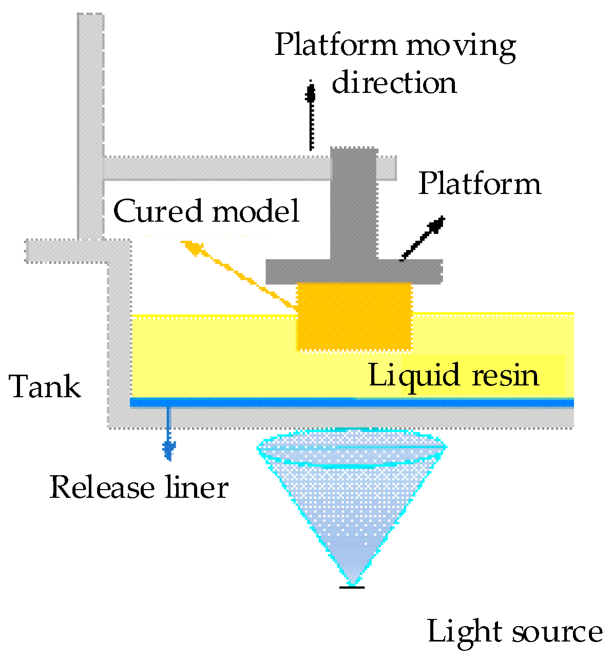
2. DLP 3D Printing Forming Principle

The core component of the DLP 3D printing forming device is the DLP projection system, which can be divided into the upper exposure 3D printing forming device and the lower exposure 3D printing forming device [19] according to the relative position of the projection equipment and the liquid tank. The DLP 3D printing molding device we designed in this work adopts the form of the lower exposure device. Compared with the upper exposure 3D printing forming device, its advantages are that the demand for the photosensitive resin is smaller, the liquid level does not need to maintain a calm level, the scraping mechanism is not required to assist, and the printing rate is faster [20]. The forming principle of DLP 3D printing with a lower exposure type is shown in Figure 1. The liquid photosensitive resin is poured inside the tank, the initial position of the printing platform is only one forming layer away from the bottom of the tank, and the cross-sectional bitmap of the 3D model of the layer is projected onto the transparent window at the bottom of the liquid tank so that the irradiated part of the photosensitive resin is polymerized to form a solid thin layer of the cross-sectional bitmap of the corresponding layer. Then the printing platform moves upward, and the distance between the solid layer and the bottom of the tank is a forming layer that is prepared for the solidification of the next layer. In order to reduce the adhesion between the solidified layer and the bottom of the liquid tank, a release liner is attached to the bottom of the liquid tank. As the next layer starts to print, the 3D model will finally be printed at the bottom of the printing platform layer by layer [21].

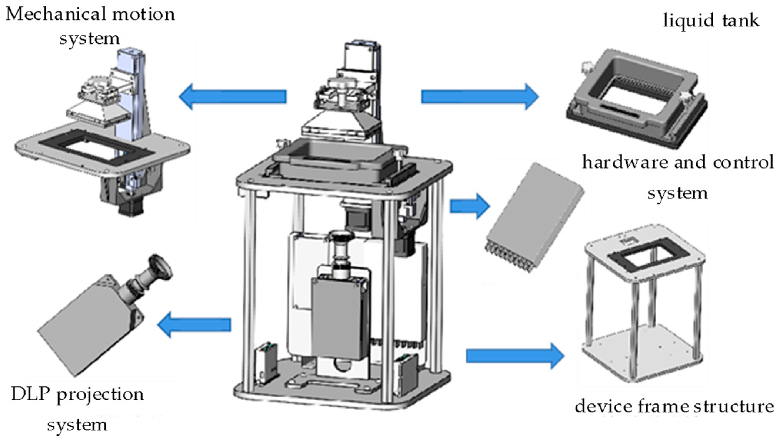
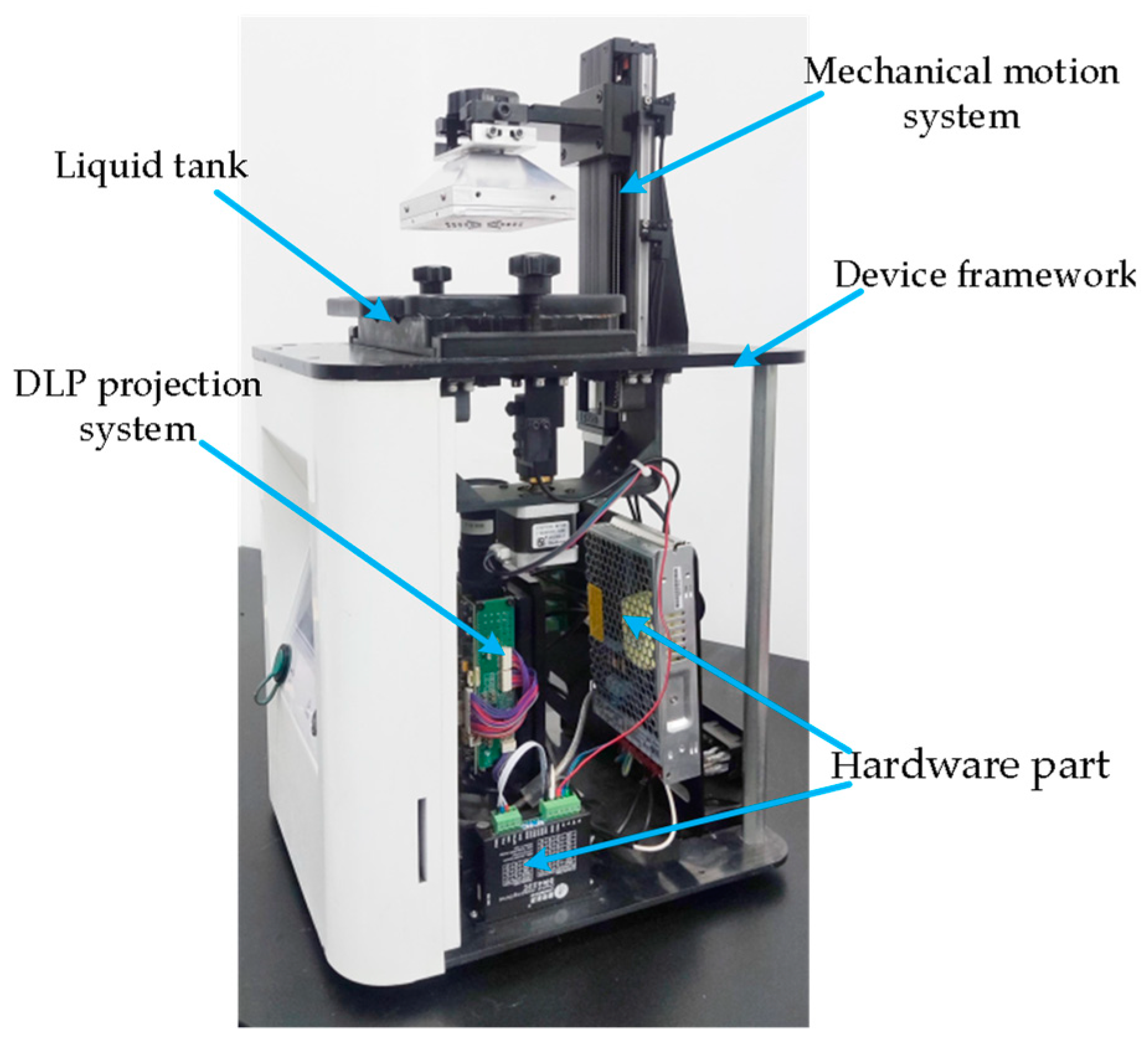
3. Overall Scheme Design

The structure of the DLP 3D printing forming device is shown in Figure 2, which is mainly composed of the DLP projection system, mechanical motion system, hardware and control system, liquid tank and device frame structure. The DLP projection system, as the core component of the 3D printing forming device, is responsible for the projection of the device, which determines the forming precision and speed of the 3D printing forming device. The mechanical motion system is responsible for the movement of the printing platform and resin tank swing, which ensure the success of the curing and bonding of each solidified layer. The core component of the hardware structure and control system is Raspberry PI, which is used to transmit users’ command and image information. The resin tank is used to place photosensitive resin materials; the device frame is to ensure the stability of the overall mechanical structure of the equipment. The DLP projection system, mechanical motion system, hardware structure and control system are the most important parts of the DLP 3D printing forming device. Therefore, this work focuses on the above three systems.

3.1. DLP Projection System

The working principle of the DLP optical projection device and UV optical machine is shown in Figure 3. It uses the light emitted by the light source to be adjusted by the optical lens and optical intensity sensing equipment, and then a clear light source area is projected through the reflection of the Digital Micromirror Device (DMD) and is amplified by the lens. The DMD is arrayed with millions of independently rotating micro-mirrors, each of which can be deflected ±12° in both positive and negative directions. It is used to control the projection angle of light, determine whether the light can reach the projection surface, and complete the optical projection, as shown in Figure 3a. Nowadays, the high-pressure mercury light source has been replaced by an LED light source because of its disadvantages, such as high-energy consumption, serious heating and short life. Based on the advantages of low-energy, small volume, and excellent performance of LED light source [22], the DLP 3D printing forming device adopts an LED UV optical machine as the projection device.
The selection of a UV optical machine should not only consider whether the light source meets the sensitive band of the resin polymerization reaction but also consider the power of the light source [23]. At present, there are three light emitting wavelengths from LED light sources, including 365, 395 and 405 nm; ultraviolet light at 365 and 395 nm can be absorbed by photosensitive resin. However, considering its power is not enough, the light source with a wavelength of 405 nm is selected. In order to meet the requirements of printing accuracy, the UV optical machine (type pro 4500, Beijing Wintech Technology Co., Ltd., Beijing, China) with a resolution of 1080 × 800 is selected. The object’s pictures of the UV optical machine are shown in Figure 3b. The optical machine projection contains 1080 pixels horizontally and 800 pixels vertically. The smaller the projected images are, the higher the resolution of the projected images are, and the better the precision and surface quality of the models are.

3.1.1. Printing Platform

In order to improve the stripping efficiency of the printing model and increase the adhesion between the model and the printing platform, a porous printing platform with easy demolding is designed and manufactured, as shown in Figure 4a. The printing platform is composed of an upper cover, a removable porous printing platform and a demolding device.
As shown in Figure 4b, the demolding device consists of a manual bolt, a disk, cylinders and a spring mechanism. Whether the first layer of the model can be cured and bonded on the printing platform is the key to the success of the whole model printing. Before printing, the cylinders of the demolding device are pushed into the removable porous printing platform, and there is a small distance between the bottom of the cylinder and the surface of the porous printing platform. The purpose of this is to increase the curing area of the first layer of the model and the printing bottom surface after the printing task is started. Thus, the adhesion of the first layer of the model on the printing bottom surface is increased, and it prevents the first layer of the model from falling from the printing platform; this improves the success rate of printing. The removable porous printing platform is positioned by cylinders extending into the small hole to prevent the bottom plate from shaking during the printing process and affecting the printing accuracy. When the printing is completed, the disk with the cylinder can move downward through the rotation of the manual bolt, and the cylinders push on the bottom of the model. Therefore, the model can be easily removed. The demolding device is restored to its original state by the spring elasticity. At the same time, the removable porous printing platform can be pulled out easily from the bottom slot for cleaning and replacement.

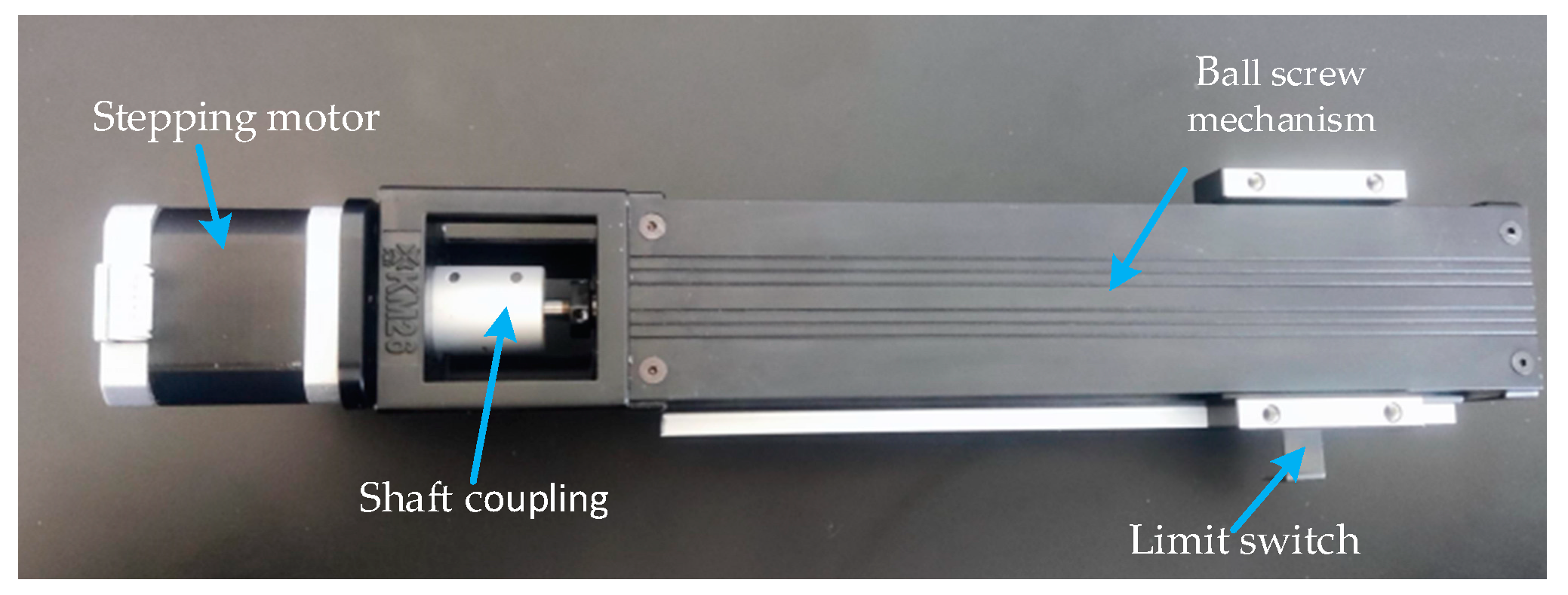
3.1.2. Z-Axis Motion Mechanism

First, the screw is selected. The calculation method of the helical pitch Ph is shown in Equation (1):
P h = V max n max
where Vmax is the maximum moving speed of the screw pair (mm/min), and nmax is the maximum speed of the motor (r/min).
The calculation method of the Dynamic Load Rating is shown in Equation (2):
C a m = 60 n m L h 3 × F m f w 100 f a
where nm is the equivalent speed (r/min), Lh stands for the expected working time (h), Fm is the equivalent load (N), fw is the load coefficient and fa is the precision class.
Screw installation is fixed at both ends, so the calculation method of the bottom diameter of thread d2 is shown in Equation (3):
d 2 0.039 F 0 L 1000 δ m
where F0 is the static friction force of the guide rail (N), L is the maximum distance between the two fixed supports (mm) and δm is the maximum allowable axial deformation (mm).
According to Equations (1)–(3), it can be calculated that the helical pitch Ph is 0.48 mm, the dynamic load rating Cam is 31.241 N and the bottom diameter of thread d2 is equal to or greater than 1.112 mm. Therefore, the specification code 0802-3 for the type of screw is selected. Its helical pitch Ph is 2 mm, dynamic load rating Cam is 1438 N, bottom diameter of thread d2 is 7.1 mm, nominal diameter d1 is 8 mm and all selections meet the transmission requirements. According to the printing size requirements, the stroke of the ball screw is 200 mm, and the stroke of the limit switch is 95 mm.
In order to ensure the accuracy requirements of the experimental printing model, the pre-selected motor model is the 42CM06 stepping motor (Dongguan Stepping motor Co., Ltd., Dongguan, China) its stepping angle is 1.8° and its rated torque is 0.6 N·m. The calculation methods of maximum acceleration torque at no load Teq1 and the maximum working load torque Teq2 of the stepping motor are shown in Equations (4) and (5):
T e q 1 = 2 π J e q n m 60 t a η
T e q 2 = F P h 2 π η i
where Jeq denotes the total moment of inertia of the stepping motor (kg·m2), Nm is rotational speed (r/min), Ta is acceleration time of stepping motor (s), F is the maximum working load on the workbench (N), Ph is the stroke of the screw (m), η is transmission efficiency and i is total transmission ratio.
According to the above calculations, the maximum load torque Teq on the loading stepping motor shaft should be:
T e q = T e q 1 + T e q 2
According to the mechanical structure, the total moment of inertia of loading on the stepping motor shaft is 1.54 × 10⁻⁵ kg.m2. When the stepping motor speed reaches 120 r/min, its acceleration time is 0.2 s, transmission efficiency is 0.85 and helical pitch is 2 mm. The maximum working load of the stepping motor is 4.06 N. According to Equations (4) and (5), Teq1 is 0.0010 N·m, and Teq2 is 0.0015 N·m, and according to Equation (6), Teq is 0.0025 N·m. It can be known that the maximum load torque on the shaft of the loading stepping motor is within the torque range of the 42CM06 stepping motor. Figure 5 shows the selected ball screw slide module.

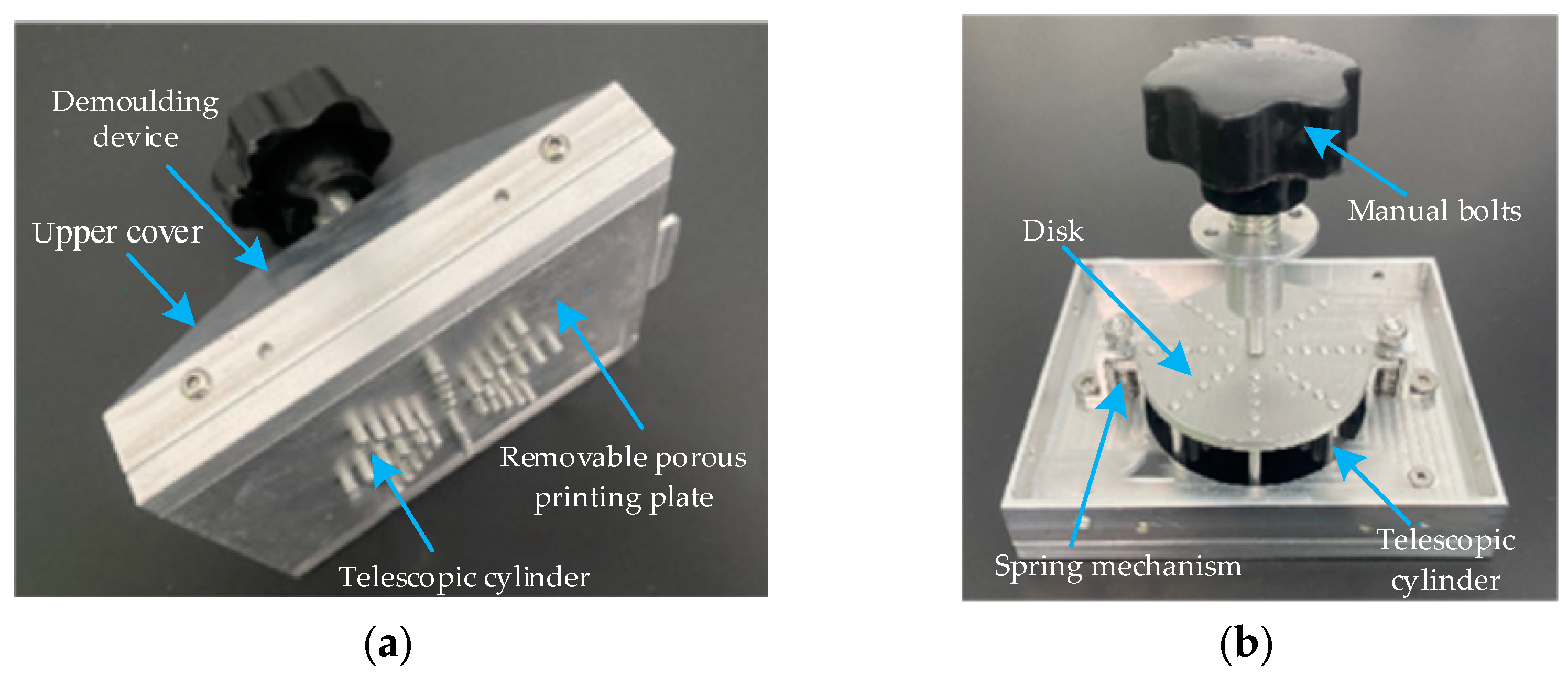
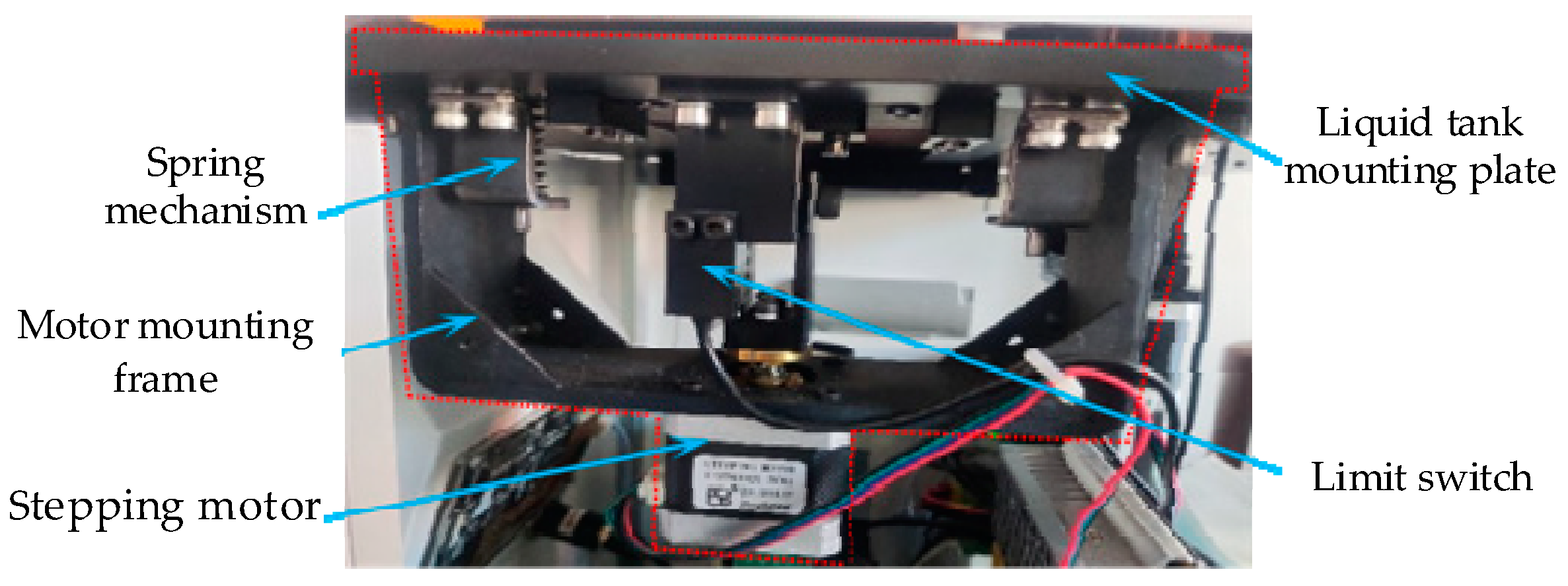
3.1.3. Swing Mechanism

The DLP 3D printing forming device adopts the direct tearing method in the process of separating the molding layer from the bottom of the liquid tank. Although the release liner is used, the forming layer still falls from the platform sometimes, thus increasing the replacement frequency of the release liner and the maintenance cost. In order to further improve the separation efficiency between the model forming layer and the bottom of the liquid tank in the printing process, reduce the replacement frequency of the release liner and the maintenance cost, a swing mechanism was designed. The swing mechanism consists of the stepping motor, limit switch, spring mechanism, motor mounting frame and liquid tank mounting plate. After each layer of the model is printed, the swing mechanism drives the liquid tank downward for a small angle and makes the forming layer easier to peel away from the bottom of the tank. Next, the stepping motor drives the liquid tank up to the horizontal position to prepare for the printing of the next layer of the model. The swing mechanism is shown in Figure 6.

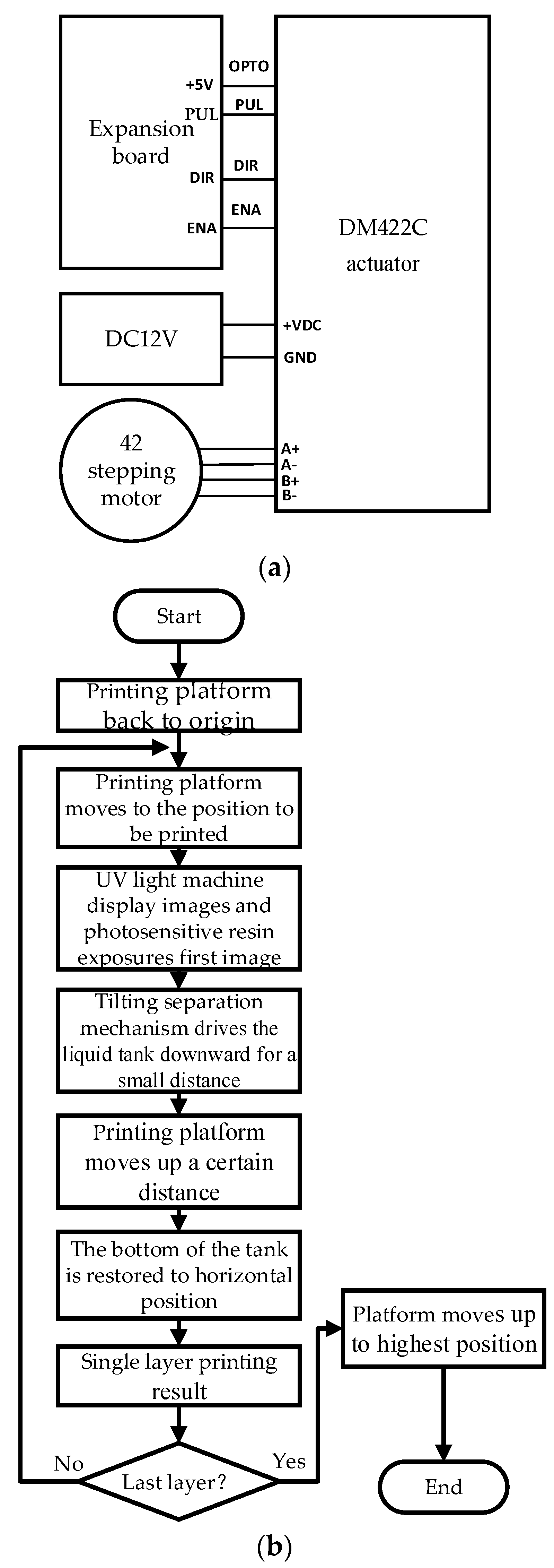
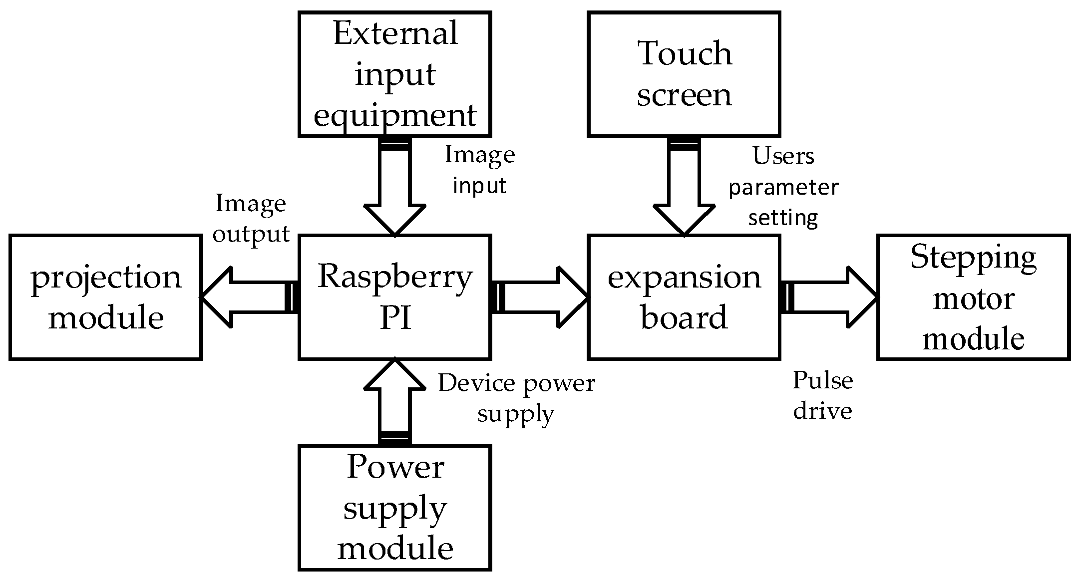
3.2. Hardware and Control System

The DLP 3D printing forming device mainly consists of a hardware system and control system. The hardware system mainly includes Raspberry PI, expansion board, motor driver and IPS touch screen, among which Raspberry PI is the control core. The Raspberry PI connects to the expansion board via its GPIO pin for command transmission. Users input 3D printing parameter commands through the IPS touch screen, and the command information is transmitted to the expansion board, which controls the movement of the stepping motor module to complete the 3D printing. The control system (Ningbo Runyes Medical Instrument Co., Ltd., Ningbo, China) is mainly composed of an image output module, stepping motor module, user control module and power module, and its structural control principle is shown in Figure 7.
Raspberry PI was officially launched by Eben Upton of the University of Cambridge in March 2013. It is a card computer with an open embedded system based on Linux. It can realize powerful functions and has the advantages of low-power consumption, small size and low price by installing the corresponding Linux system and corresponding applications. In particular, Raspberry PI has WIFI, Bluetooth and other functions, which facilitates the realization of the wireless online printing function of the printer and facilitates the detection and evaluation of product quality problems in the printing process [24]. The quality problems caused by the shedding of the model layer are expected to be solved by adding a buffer layer [25].
The HDMI interface of Raspberry PI is used to control the output of images. First, users insert the YXP image set file, which contains the completed slices, into the port of the device. The Raspberry PI image parsing and display program reads the PNG image in the file and transmits the image information to the projection system to control the projection system and complete the projection work. Users determine the printing process of the projection system by inputting the exposure time and other parameters. The printing device will feed back the current printing progress to the user’s control interface. When the projection system receives pause or stop command information from users, the image parsing projection program immediately executes the current command and enters the empty loop. The program flow is shown in Figure 8.
The stepping motor control module is the core of the control system, which directly determines the accuracy of the 3D printing model. The Z-axis motion control and position limit of the 3D printing device are realized by using a digital actuator and a U-slot photoelectric limit switch. The expansion board realizes the driving function of the motor, photoelectric limit switch, touch screen driver and other components. Its interface is simple, and data transmission is convenient. The DM422C stepping motor driver (Shenzhen Leysai Intelligent Control Co., Ltd., Shenzhen, China), with the function of over-voltage and short circuit protection, adopts the connection method of a common anode. The PUL interface transmits the pulse signal, and the stepping motor rotates at an angle into a pulse signal. The DIR interface transmits the direction signal, and it is used to control the motor steering. The OPTO interface is connected to a 5 V power supply, and the ENA interface transmits the enable control signal. The DM422C and 42 stepping motor wiring diagram is shown in Figure 9a. The number and frequency of pulses transmitted by the stepping motor to the driver through the expansion board can accurately control the speed and position of Z-axis movement. The specific control process is shown in Figure 9b. The LRS-150-12 switching power supply is adopted for the device, which can convert the alternating current of the home into 5 and 12 V of direct current to supply power to each module of the device and ensure the normal operation of the DLP 3D printing forming device and completion of the printing work.

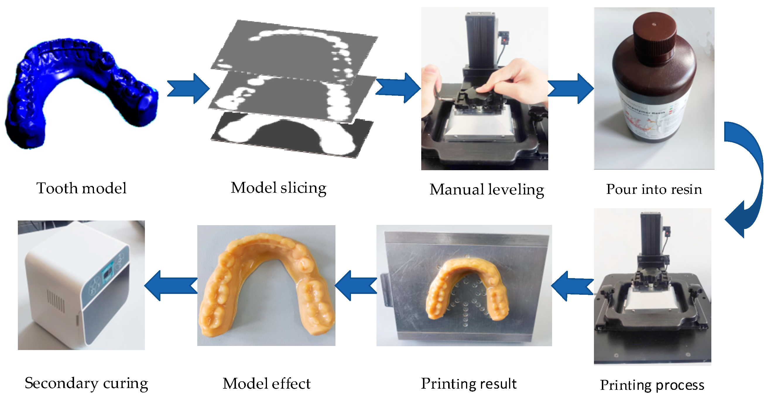
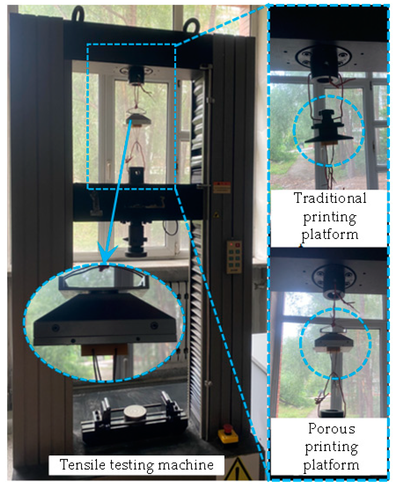
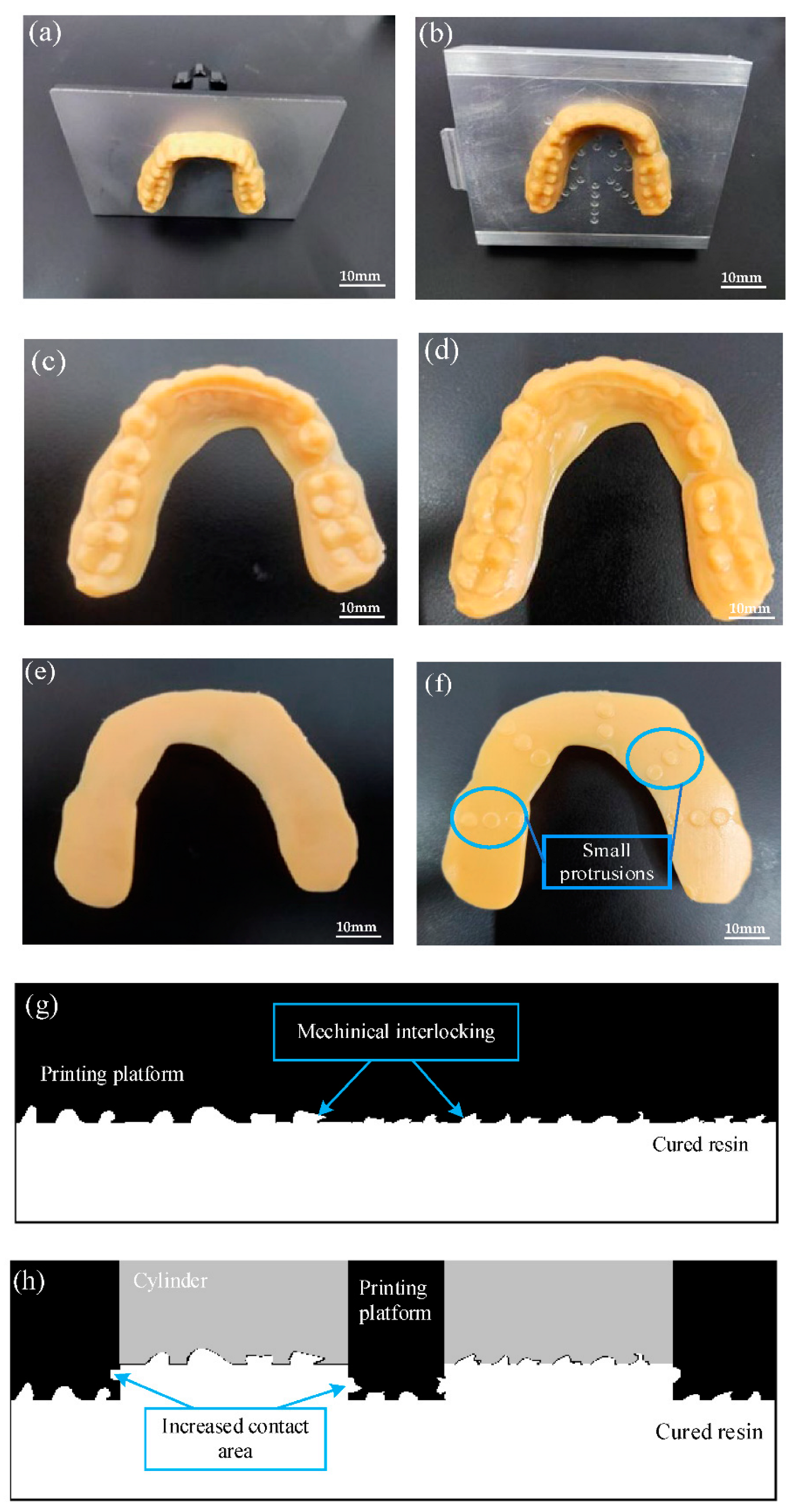
4. Experimental Verification

According to the DLP projection system, a mechanical motion system, hardware and control system, liquid tank and device frame structure were selected in this work, and a DLP 3D printing forming device was built, which met the basic requirements of the experiment. The cost is about 25,000 CNY, which is lower than that of the same performance device in the market, so it has a certain cost advantage. The device is suitable for most photosensitive resins with 405 nm absorption in the market, such as common rigid resins, flexible resins, dental biocompatibility resins and other molding materials. The device is shown in Figure 10, and the device parameters are shown in Table 1. Figure 11 is the adhesion test figure of the DLP 3D printing platform. Blocks with length, width and height of 40 × 40 × 10 mm are printed by this device. The CMT5105 universal testing machine is used to carry out a tensile test at a speed of 1 mm/min. The maximum force of separation from the traditional printing platform is 195.2 N. However, the maximum force of separation from the porous printing platform is 220.7 N, which verifies that the device has enhanced adhesion.
The DLP 3D printing technology is a suitable 3D printing technology for dental applications because the dental models printed by the DLP 3D printing technology have high accuracy, surface hardness and bending strength [26]. Many dental applications can be effectively printed using DLP 3D printing technology, including dental models, dental crowns, custom trays, etc. [27]. In this experiment, the adult tooth model was selected for the comparative printing experiment, and the same adult tooth model was printed and compared by the traditional printing device and the printing device that was designed in this paper. First, a 3D model of an adult tooth was established and sliced, and the slicing file was imported into the device port. Then, the printing platform was leveled, and liquid resin was poured into the liquid tank before printing. After the printing work was completed, the tooth model was removed and cured secondly. The specific process is shown in Figure 12.
Figure 13 is the printing result of the adult tooth model, in which Figure 13a,c,e are the printing results from traditional equipment, and Figure 13b,d,f are the printing results from the equipment studied in this paper. It can be seen that the 3D printed tooth model studied in this paper maintains good surface quality and printing accuracy. As shown in Figure 13f, small protrusions with uniform distribution are distributed at the bottom of the tooth model, indicating that the curing area at the bottom of the printing platform and the bottom of the model has increased. As shown in Figure 13g,h, due to the longer exposure time of the bottom layer, the resin solidifies in the groove of the printing platform and forms a riveted structure. The adhesion area between the bottom resin layer and the printing platform increases. According to the adhesion mechanical connection theory, the adhesion between the resin coating and the printing platform increases to a certain extent. The traditional printing platform needs to scrape the tooth model with a scraper. The printing platform designed by this device only needs to push out the model with a manual bolt, which has high stripping efficiency. At the same time, the design of a detachable printing platform is convenient for cleaning and replacement and reduces the maintenance cost of the traditional printing platform in the later period.

5. Conclusions

(1) A DLP 3D printing forming device with enhanced adhesion and efficient demolding was designed and manufactured. The device solved the problems of model shedding and difficult model stripping in the printing process, and it has a good application prospect and provided an experimental basis for subsequent theoretical research.
(2) By designing the structure of the removable porous printing platform, the efficiency of the 3D printing model was improved, and the damage to the printing platform caused by the traditional demolding method was reduced. In the process of printing the model, the porous structure was used to increase the curing area between the first layer of the model and the printing platform so that the model was easier to adhere to the printing platform and improve the success rate of printing.
(3) Through the design of the swing mechanism, after the printing of each model layer, the stepping motor and limit switch device was used to make the bottom side of the liquid tank tilt down at a small angle, reducing the lifting force of the printing platform, and making the model more easily attached to the bottom of the printing platform.
(4) The designed printing device with Raspberry PI as the control core had the advantages of simple structure, convenient operation, stable operation of each module of the control system, high precision and high speed.

Author Contributions

Data curation, Y.X.; Formal analysis, T.M. and H.W.; Funding acquisition, M.J. and B.X.; Methodology, T.J., Y.Y. and Y.X.; Writing—original draft, T.J. and B.Y.; Writing—review and editing, M.J. and B.X. All authors have read and agreed to the published version of the manuscript.

Funding

Supported by the Guiding Innovation Fund Project of Northeast Petroleum University (2021YDL-13 and 2022YDL-06), Daqing City guiding science and technology project (zd-2021-41), the Scientific Research Start-up Fund Project of Northeast Petroleum University (2021KQ09 and 2019KQ67), National Natural Science Foundation of China (52075090), and Supported by the National Key R&D Program of China (2017YFD0601004).

Institutional Review Board Statement

Not applicable.

Informed Consent Statement

Not applicable.

Data Availability Statement

Not applicable.

Conflicts of Interest

The authors declare no conflict of interest. The funders had no role in the design of the study; in the collection, analyses, or interpretation of data; in the writing of the manuscript, or in the decision to publish the results.

References

  1. Bahnini, I.; Rivette, M.; Rechia, A.; Siadat, A.; Elmesbahi, A. Additive manufacturing technology: The status, applications, and prospects. Int. J. Adv. Manuf. Technol. 2018, 97, 147–161. [Google Scholar] [CrossRef] [Green Version]
  2. Lu, B.; Li, D. Development of the Additive Manufacturing (3D printing) Technology. Mach. Build. Autom. 2013, 42, 1–4. [Google Scholar]
  3. Khorasani, M.; Loy, J.; Ghasemi, A.H.; Sharabian, E.; Leary, M.; Mirafzal, H.; Cochrane, P.; Rolfe, B.; Gibson, I. A review of Industry 4.0 and additive manufacturing synery. Rapid Prototyp. J. 2022. Ahead-of-print. [Google Scholar] [CrossRef]
  4. Zhao, Y.; Liu, C.; Congbo, X.; Wenqiu, L. Development Status of 3D Printing Technology and Equipment. Mech. Res. Appl. 2021, 34, 224–227. [Google Scholar]
  5. Li, Y.; Li, D.; Li, B. Introduction to stereolithography and application. J. Appl. Opt. 1999, 3, 35–37. [Google Scholar]
  6. Bourell, D.L. Sintering in Laser Sintering. JOM 2016, 68, 885–889. [Google Scholar] [CrossRef]
  7. Mueller, B.; Kochan, D. Laminated object manufacturing for rapid tooling and patternmaking in foundry industry. Comput. Ind. 1999, 39, 47–53. [Google Scholar] [CrossRef]
  8. Daminabo, S.; Goel, S.; Grammatikos, S.; Nezhad, H.Y.; Thakur, V.K. FDM-based Additive Manufacturing (3D Printing): Techniques for Polymer Material Systems. Mater. Today 2020, 16, 100248. [Google Scholar] [CrossRef]
  9. Pagac, M.; Hajnys, J.; Ma, Q.P.; Jancar, L.; Jansa, J.; Stefek, P.; Mesicek, J. A Review of Vat Photopolymerization Technology: Materials, Applications, Challenges, and Future Trends of 3D Printing. Polymers 2021, 13, 598. [Google Scholar] [CrossRef] [PubMed]
  10. Anunmana, C.; Ueawitthayasuporn, C.; Kiattavorncharoen, S.; Thanasrisuebwong, P. In Vitro Comparison of Surgical Implant Placement Accuracy Using Guides Fabricated by Three Different Additive Technologies. Appl. Sci. 2020, 10, 7791. [Google Scholar] [CrossRef]
  11. Reich, S.; Berndt, S.; Kühne, C.; Herstell, H. Accuracy of 3D-Printed Occlusal Devices of Different Volumes Using a Digital Light Processing Printer. Appl. Sci. 2022, 12, 1576. [Google Scholar] [CrossRef]
  12. Zarek, M.; Layani, M.; Eliazar, S.; Mansour, N.; Cooperstein, I.; Shukrun, E.; Szlar, A. 4D printing shape memory polymers for dynamic jewellery and fashionwear. Virtual Phys. Prototyp. 2016, 11, 263–270. [Google Scholar] [CrossRef]
  13. Mu, Q.; Wang, L.; Dunn, C.K.; Kuang, X.; Duan, F.; Zhang, Z.; Qi, H.J.; Wang, T. Digital light processing 3D printing of conductive complex structures. Addit. Manuf. 2017, 18, 74–83. [Google Scholar] [CrossRef]
  14. Zhao, G.; Liu, Z.; Li, Y. Stereolithography: Principle, Technologies, Applications and Novel Developments. Mech. Electr. Eng. Technol. 2020, 49, 7. [Google Scholar]
  15. Wang, Q.; Yang, X.; Hui, Z.; Zhao, R.; Yang, Z.; Guo, M.; Li, Y. Influence of Micro-texture Characteristics of Substrate on Separation Force in Constrained-surface Projection Based Stereolithography. J. Mech. Eng. 2021, 57, 196–206. [Google Scholar]
  16. Huang, Y.M.; Jiang, C. On-line force monitoring of platform ascending rapid prototyping system. J. Mater. Processing Technol. 2005, 159, 257–264. [Google Scholar] [CrossRef]
  17. Pan, Y.; Zhou, C.; Chen, Y. A fast mask projection stereolithography process for fabricating digital models in minutes. J. Manuf. Sci. Eng. 2012, 134, 051011. [Google Scholar] [CrossRef]
  18. Tumbleston, J.R.; Shirvanyants, D.; Ermoshkin, N.; Janusziewicz, R.; Johnson, A.R.; Kelly, D.; Chen, K.; Pinschmidt, R.; Rolland, J.P.; Rrmoshkin, A.; et al. Continuous liquid interface production of 3D objects. Science 2015, 347, 1349–1352. [Google Scholar] [CrossRef]
  19. Fang, H.; Chen, J. 3D Printing Based on Digital Light Processing Technology. J. Beijing Univ. Technol. 2015, 41, 1775–1782. [Google Scholar]
  20. Quan, H.; Zhang, T.; Xu, H.; Luo, S.; Nie, J.; Zhu, X. Photo-curing 3D printing technique and its challenges. Bioact. Mater. 2020, 5, 6. [Google Scholar] [CrossRef]
  21. Barone, S.; Neri, P.; Paoli, A.; Razionale, A.; Tamburrino, F. Development of a DLP 3D printer for orthodontic applications. Procedia Manuf. 2019, 38, 1017–1025. [Google Scholar] [CrossRef]
  22. Zhou, X.; Wang, Z. Design and realization of 3D printer based on the principle of DLP. Manuf. Technol. Mach. Tool 2018, 4, 4. [Google Scholar]
  23. Liao, Z.; Deng, J. Technical Analysis of DLP Light Curing Rapid Prototyping Equipment. Mech. Electr. Eng. Technol. 2018, 47, 66–69. [Google Scholar]
  24. Wu, L.; Liu, Z.; Guan, Y.; Cui, K.; Jian, M.; Qin, Y.; Li, Y.; Yang, F.; Yang, T. Visual presentation for monitoring layer-wise curing quality in DLP 3D printing. Rapid Prototyp. J. 2021, 27, 1776–1790. [Google Scholar] [CrossRef]
  25. Dave, H.K.; Karumuri, R.T.; Prajapati, A.R.; Rajpurohit, S.R. Specific energy absorption during compression testing of ABS and FPU parts fabricated using LCD-SLA based 3D printer. Rapid Prototyp. J. 2022. Ahead-of-print. [Google Scholar] [CrossRef]
  26. Kim, H.J.; Lim, S.W.; Lee, M.K.; Ju, S.W.; Park, S.H.; Ahn, J.S.; Hwang, K.G. Which Three-Dimensional Printing Technology Can Replace Conventional Manual Method of Manufacturing Oral Appliance? A Preliminary Comparative Study of Physical and Mechanical Properties. Appl. Sci. 2022, 12, 130. [Google Scholar] [CrossRef]
  27. Alageel, O. Three-dimensional printing technologies for dental prosthesis: A review. Rapid Prototyp. J. 2022. Ahead-of-print. [Google Scholar] [CrossRef]
Figure 1. Lower exposure DLP 3D printing forming schematic diagram.
Applsci 12 07373 g001
Figure 2. Structure of the DLP 3D printing molding device.
Applsci 12 07373 g002
Figure 3. DMD projection schematic diagram and machine. (a) DMD projection schematic diagram; (b) UV light machine.
Applsci 12 07373 g003
Figure 4. Structure diagram of the porous printing platform for easy demolding. (a) The overall structure diagram of the printing platform; (b) Structure diagram of the demolding device.
Applsci 12 07373 g004
Figure 5. Z-axis screw slide module.
Applsci 12 07373 g005
Figure 6. Swing mechanism.
Applsci 12 07373 g006
Figure 7. Hardware control structure diagram.
Applsci 12 07373 g007
Figure 8. Flow chart of projection program for image analysis.
Applsci 12 07373 g008
Figure 9. Schematic diagram and glow diagram of the stepping motor. (a) Schematic diagram of the connection of the 42-stepping motor; (b) Flow diagram of the stepping motor control module.
Applsci 12 07373 g009
Figure 10. DLP 3D printing forming device.
Applsci 12 07373 g010
Figure 11. Adhesion test figure of printing platform.
Applsci 12 07373 g011
Figure 12. Operation flow diagram of DLP 3D printing forming device.
Applsci 12 07373 g012
Figure 13. (af) Contrast diagram of printing model; (g,h) Adhesion mechanism diagram of resin.
Applsci 12 07373 g013
Table 1. Parameters of DLP 3D printing device.
Device ParametersValue
Printer size320 × 300 × 585 mm
Input parametersAC 220 V/50 HZ
Printing accuracy±0.05 mm
Recommended printing thickness0.1 mm
Printing speed40 mm/h
Maximum printing size89.6 × 56 × 95 mm
Power65 W
Net weight20 Kg
Publisher’s Note: MDPI stays neutral with regard to jurisdictional claims in published maps and institutional affiliations.

