1. Introduction
With the excellent performance of continuum robots, soft robots have attracted lots of attention in research. Inspired by creatures in nature such as octopuses and elephants [
1,
2,
3], researchers have developed continuum robots with super-redundant degrees of freedom. Flexibility of the continuum is expected to drive robots to operate adaptively in unstructured environments, especially in the service, rescue, and medical care fields. A flexible manipulator can be considered a continuum robot, which exhibits flexibility, variable stiffness, and high dexterity during motion and has strong versatility and adaptability. Highly dexterous tasks such as human-interactive grasping and exploration in confined regions can be realized with a flexible manipulator. This is one of the reasons for the rapidly growing demand for flexible robotic arms in the industry, robot-assisted surgery, and other fields.
Researchers have made progress in manufacturing soft manipulators with cable-driven systems with the advancements in material technologies thanks to modeling kinematics and dynamics equations, which conveniently translate the rotation of a servo motor into the change in cable length [
4,
5]. Researchers have also developed pneumatic soft manipulators [
6,
7,
8], such as “Octarm” [
9]; this kind of manipulator takes advantage of the expansion and deformation properties of rubber materials and continuously deforms to achieve a certain shape. It has more advantages than its rigid counterpart with a suitable design. The longer the arm of a soft robot, the broader its application scenarios and the more dexterous its movements. An emerging problem is that it also requires more control of the robot arm. Therefore, the multi-section tandem design is a structure commonly used for pneumatic manipulators and the chambers of each segment in the actuators [
10,
11].
1.1. Related Works
A pneumatic flexible manipulator achieves motion mainly through non-linear deformation of the silicone material, which is different from the rotational motion of a rigid robotic arm at the joints. Therefore, chambers become the most common actuators in pneumatic arms, which act like pneumatic artificial muscles and are realized by the expansion or contraction of the chambers [
12,
13,
14]. The structural design of the chamber needs to consider a sufficient deformation capacity, and the structure of the bellows can provide redundant surfaces to ensure that the chamber can elongate and contract. Therefore, three chambers used in parallel to form a section of an arm are widely used in the structural design of pneumatic manipulators. An arm composed of multiple segments connected in series can achieve more flexible movements. It is necessary to fix these chambers with components such as a manifold to connect each section [
15]. The novel flexible connection plate proposed in this paper has fine mechanical properties and can be used as a general design method for multi-segment structures [
16]. A popular approach to modeling continuum robots has been already established to model rigid manipulators: researchers select the key kinematic parameters in a model—the arc, the curvature, and the orientation angle—to establish a transformation equation in the task space and apply it at every segment of the manipulator [
17,
18,
19]. The shape and position of the soft manipulator are hard to describe because of the flexibility of the material. It is usually made up of silicone and shows nonlinear deformation. A robotic arm consisting of rotating or moving joints uses four linkage parameters to describe the mechanism’s motion relationship, called the Denavit–Hartenberg method. However, obtaining accurate kinematic equations for flexible manipulators is usually challenging [
20]. Wei et al. presented a ball joint for a cable-driven soft manipulator considering the blocking effect [
21]. It can be efficient in a cable-driven manipulator but is unsuitable for a structure that expands or contracts. Similarly, establishing a discrete model is essential to illustrating the change in parameters for dynamics modeling [
22,
23]. Stiffness is not a constant factor in the model because of the nonlinear elasticity. The position of the connecting plate in relation to the chambers is relatively stationary, and this fact causes stress to easily accumulate due to actuation pressure from the chambers. Therefore, as the components of a soft manipulator, it could affect the accuracy of the position and shape via the conduction of actuation moment from chambers. Additionally, the connecting plate prevents stress from coupling due to the flexible deformation.
To sum up, the development of soft manipulators originated from bionics, and their feasibility has been proven using kinematic modeling. However, further research is needed due to the limitations of the materials’ characteristics and the structural design. Based on bionics, this paper aims to design a novel connecting plate as a flexible joint to achieve greater flexibility for the manipulator.
1.2. Contribution of the Paper
According to the characteristics of flexible materials in most soft manipulators, nonlinear deformation can significantly affect movement accuracy [
24]. As the main component where axial force concentrates, changes to the soft connecting plate could resolve this issue.
The contributions of this article are summarized as follows:
Section 2 proposes a novel connecting plate based on lightweight and flexible design principles. Different modules of the connecting plate were designed to mimic the muscle function of an octopus arm. The related design includes a joint plate made of rubber and a 3D-printer manifold.
Section 3 illustrates the design concept and modeling for the stress features on a connecting plate. We describe the relationship between infusion pressure and moments of the manipulator.
Section 4 analyzes the multi-section structure via FEM and verifies the feasibility of this novel design. Finally, this paper presents an analysis in the subsection describing the experiments.
Section 5 summarizes the work presented in this paper.
2. Structural Design of Connecting Plate
The bionic mechanism of a soft manipulator was derived from research on the tissue structure of an elephant’s trunk and an octopus arm [
25]. From the anatomy of an octopus arm, the researchers found that the sectional structure of an octopus arm can be divided into three parts, as shown in
Figure 1a. Longitudinal muscle (LM) fibers are distributed to support and maintain the shape of the tentacles; in the middle area, transverse muscle (TM) fibers separate distinct musculature regions and wrap around the axial nerve (AN) cord and innermost blood vessels. The idea behind the structural design of the flexible connecting plate is to map the function and cross-sectional distribution of the octopus muscle tissue to different components in the connecting plate. This paper presents a bionic oblique muscle (BOM) as the middle layer to connect each section, as shown in
Figure 1b. Clemson University’s Bartow designed a typical rigid plate for fixing the chambers [
15]. We adopted a similar design and simplified the LM into three groups of chambers, which make up a connecting plate by bolting it to the chamber fastening (CF). The TM fibers in the design of the cross-sectional structure are replaced with layer fastening (LF). Its function is to constrain the deformation of the central area of the BOM. When the connecting plate deforms with three chambers, the LF can reduce the interaction between different deformation areas of the BOM.
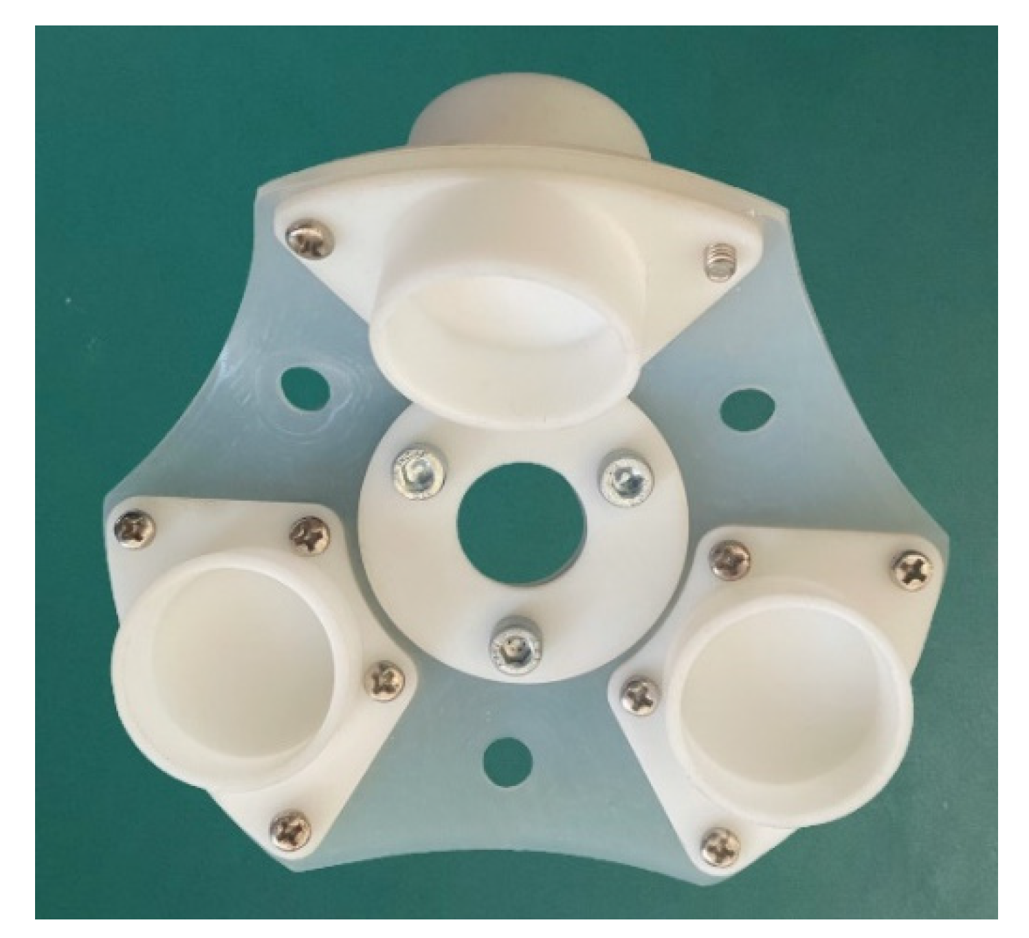
Modules CF and LF were obtained by 3D printing. The middle layer BOM was made of silicone material. The BOM had flexible characteristics, and when the connecting plate was subjected to the force of a single chamber, local deformation occured as shown in
Figure 2. The silicone material used here was fumed silicone rubber NE9530 manufactured by DJSilicone. We substituted the uniaxial tensile test results into the three-parameter Yeoh model, where the material parameters
= 0.13,
= 0.04,
= 0.007, and Young’s modulus was
Pa.
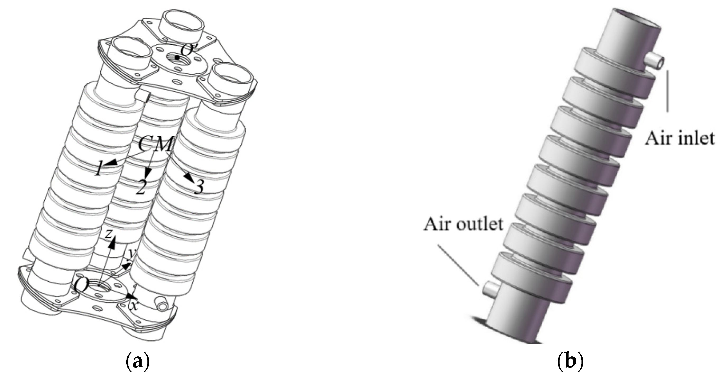
This paper presents a novel soft pneumatic manipulator, which consists of double connecting plates for modularized assembly; the three motion chambers were classified using numbers 1, 2, and 3 and arranged counterclockwise; and the inner diameter of each chamber was 130 mm. Taking a single-section manipulator as an example, the center point O of the connecting plate at the bottom of the manipulator is the origin of the Cartesian space coordinate system, and point O’ represents the end center point of the last segment of the manipulator, as shown in
Figure 3a. These chambers are assembled with the plate as pneumatic artificial muscles (PAMs). The role of the chambers here is similar to PAMs, and we set two air pipe joints in each chamber for pneumatic control. The manipulator’s design aims to achieve modular assembly. The plate is primarily made of silicone. Therefore, the plate is lighter than other products [
26]. All of the components consist of chambers, and BOMs can be produced by molding. This paper’s modeling and analysis have guiding significance for structural improvement in these manipulators.
3. Modeling of the Actuator
To analyze the stress variation in the robot arm during motion, the connecting plate was designed as a structure with a mirror image on both sides and the middle layer BOM bears the main stress. When performing kinematic modeling, researchers need to also consider the nonlinear compressive and shear stresses, which differ from the conditions that only consider expansion. A pneumatic soft manipulator is driven by air pressure, which is balanced with the bending moment during movement.
is the driving moment produced by pressure
of three chambers.
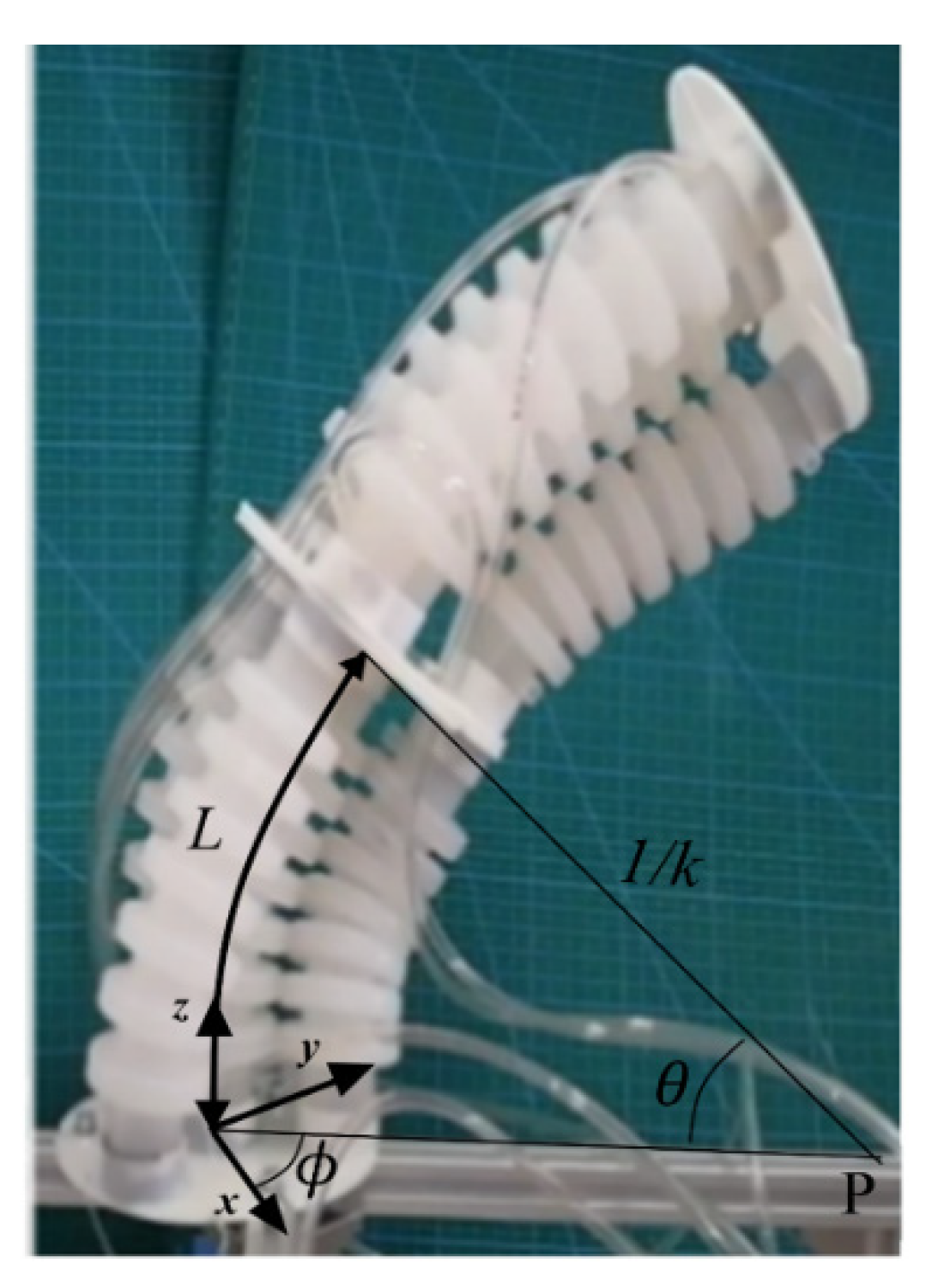
is the elastic moment of the soft manipulator of elasticity. When defining the kinematics of a soft manipulator, deflection angle
, bending angle
, and curvature
k are the main parameters and can be obtained by mapping the length of the manipulator to the task space. There is a simplified constant curvature model of the soft manipulator in
Figure 4. L is the arc length,
P is the center of curvature, and the radius of curvature is
.
3.1. Driving Moment
The chamber is subjected to changing air pressure, which generates a driving torque that allows the robot arm to achieve a bending motion. Considering the principle of virtual work, the flexible plate is an important component that can transfer the actuation moments from the bottom chambers to the next section. Therefore, the driving moment of the soft manipulator can be written as follows:
where
is the driving force of the chamber generated by the infused pressure and
is the vector radius of the soft manipulator. The driving force of the chamber
can be obtained by the following:
where
is the area of the inner circle at the connection of the chamber and
is its radius. Additionally,
is the input air pressure in each chamber.
3.2. Elastic Bending Moment of BOM
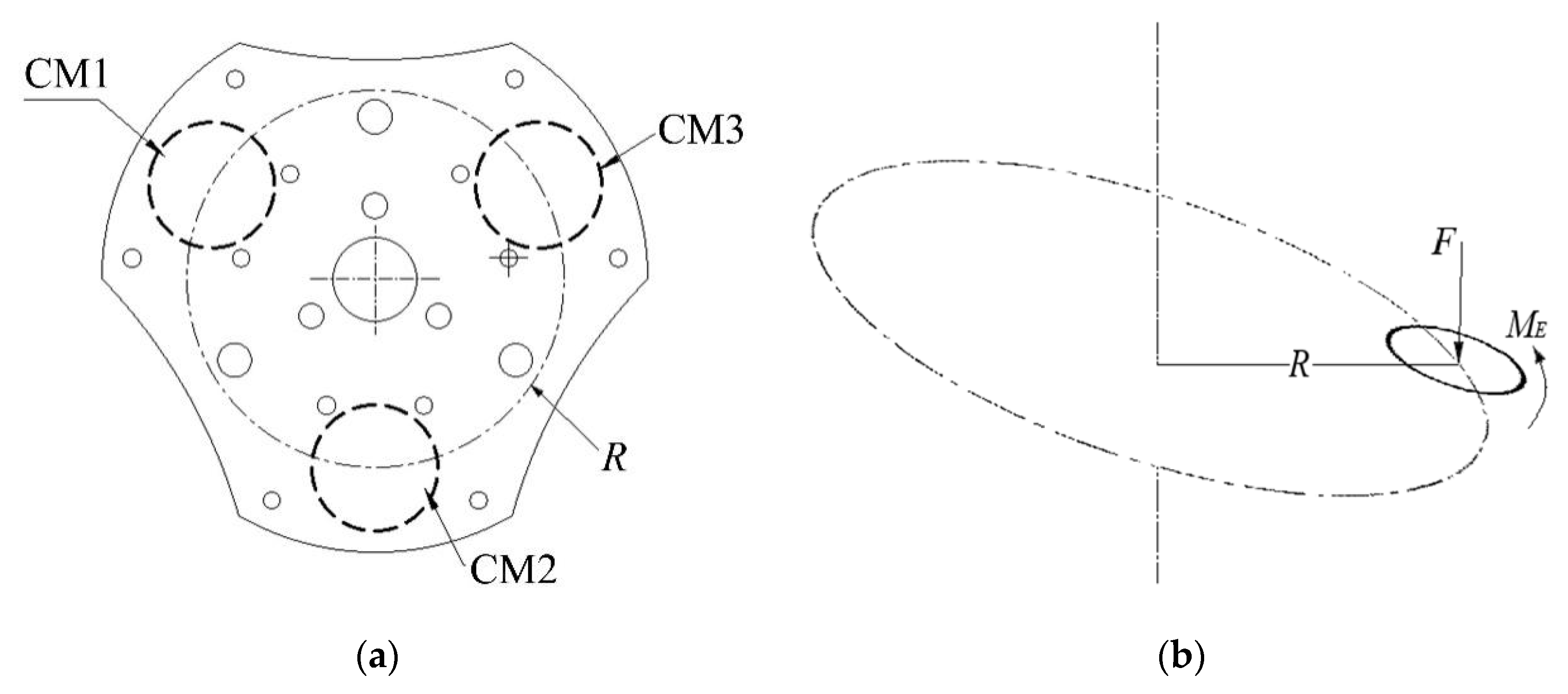
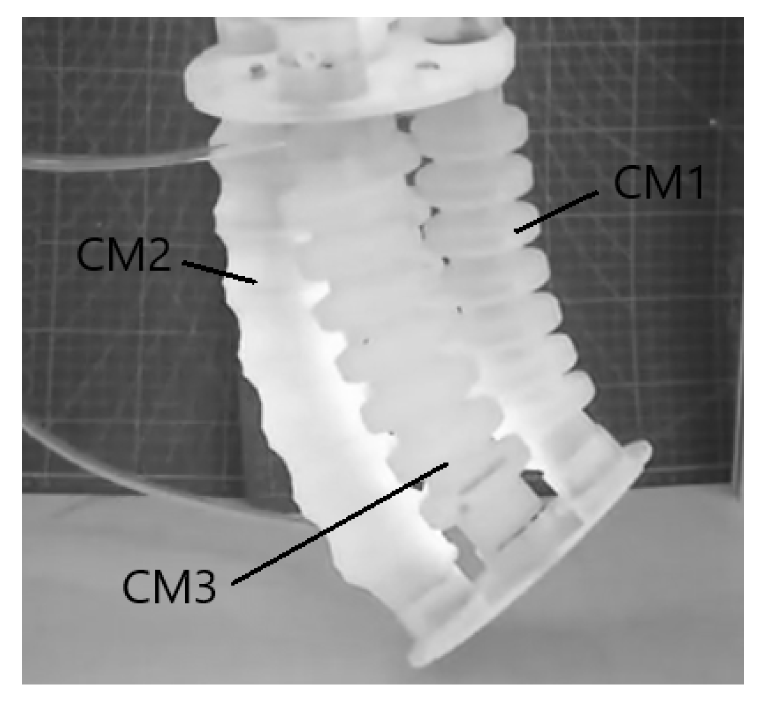
During movement of the manipulator, the connecting plate is subjected to the air pressure of the pneumatic actuators on both sides simultaneously, and the stress values on both sides of the connecting plate are different. Then, the connecting plate bears the bending moment. CM in
Figure 5a represents the area where the connecting plate is subjected to air pressure, and
Figure 5b represents the force balance of the connecting plate at the connection of a chamber in a simplified way. The elastic bending moment
is the sum of the elastic bending moments produced by the three chambers. Considering the stress–strain relationship, the elastic bending moment of the soft manipulator for BOM can be obtained as follows:
where
is the area that CF makes contacts with BOM.
is the actual stress generated by the soft actuator on BOM.
R is the radius that we defined as shown in
Figure 5.
This paper assumes that the chambers only separately produce forces in the z and r axes on the BOM as an axial-symmetric element. The finite element method has been applied to the nonlinear deformation of flexible materials. Some works model the characteristics using the Yeoh model because it can be a simple stretching motion for some manipulators. However, the BOM would be more complicated, especially if we consider compression, which is different from stretching due to its nonlinear characteristics.
Compared with related works, the Navier–Cauchy function was introduced to improve the accuracy of describing stretching and compression on a scale. Based on the Navier–Cauchy equations and illustrated by the Legendre function [
27], we combine the modulus with at least four material coefficients and parameters to fit the elastic modulus of the connecting plate:
In Formula (4), there are two task space influence coefficients: and .
With
as the initial Young’s modulus of the silicone material, it can be tested from the tensile experiment before showing nonlinear characteristics in the first tensile stage [
28]. Additionally,
is Poisson’s ratio. In Equation (6), the material coefficients
and
are as follows:
For further fitting, the nonlinear characteristics of the orientation angle exhibit material coefficients
and
, as follows:
Furthermore, the BOM can be assembled for
n layers in terms of the practical requirement. Additionally, curvature
k as an important factor [
29]:
Therefore, we can derive the stiffness matrix in Equation (8). With
and
as the stress and strain, we can separately determine the direction of axis
z and the radius:
4. Structural Analysis
Taking a manipulator as an example, at any combination of air-pressure values in the two chambers, the manipulator can achieve six bending directions; when the air-pressure values in the three chambers are all different, the manipulator can achieve flexible movement in any direction. Therefore, the manipulator designed in this paper mainly uses the pressure difference in each chamber to change the manipulator’s shape. As shown in
Figure 6, the air pressure in chamber 1 remained constant. The driving device delivered the gas to increase the air pressure in chambers 2 and 3 to bend the manipulator. The air pressure in the chambers of the manipulator comes from the air pump.
Considering the torque balance, the silicone chamber generates a driving torque on the connecting plate through inflation and elongation. Torsion and bending of the chambers cause stress to concentrate on the connecting plate. The plate is also subject to drive torque, making it more difficult to control the manipulator. The rigid connecting plate is made of ABS material, which has high rigidity characteristics and decreases the manipulator’s performance in transmitting the driving torque. The novel flexible connecting plate can reduce the influence of the force coupling generated by the movement of the chamber through the bending deformation of its BOM module. We designed a rigid connecting plate with the same-sized radius and thickness via 3D printing, and the relevant parameters and simulation conditions of the rigid and flexible connection plates required for the test are provided in
Table 1.
Based on the finite element method, we used software to simulate and then to verify the detailed stress effect on the movement [
30,
31].
Figure 7 shows the stress distribution of the two connecting plates. For the RC plate, EF is the base used to connect two connecting plates and to support the basic shape of the soft manipulator. For radial restriction, the position of CF would be the ideal boundary in the motion. HL is the hole used for fixing another rigid plate in place to complete the modular assembly of the manipulator. According to the model and Equations (3) and (9), we can determine the possible air pressures and loads in the simulation. Therefore, the simulation results of two kinds of connection plates under preset conditions are shown in the following figures:
According to the simulation test results in
Figure 7, the stress in the RC tends to be concentrated in the central area. On the same scale, we easily obtain the conclusion that the stress-concentration effect of BOM is significantly smaller than that of RC. Due to the rigidity of RC, it couples the driving torque from the previous robotic arm module into a total driving force and transmits it to the next robotic arm module during the movement, which causes the control system to fail in effectively responding to the driving torques respectively generated from three chambers. The finite element simulation test can summarize the nonlinear relation via the stiffness characteristics in typical pneumatic soft arms. Although it leads to more significant stresses and strains on the BOM than RC, these stresses and strains are less likely to be transferred to other motion components.
The ends of the three chambers are fixed in the same plane by the connecting plate. When the air-pressure values in the three chambers are different, the manipulator extends axially and bends toward the chamber with lower air pressure. When we consider the bending moment on the connecting plate, the air pressure borne by the connecting plate is regarded as a whole. However, considering the flexible material property of the overall flexible manipulator, the soft manipulator is assembled with multi-segment modules bending towards different directions in space: one side of the chamber is driven by air pressure to produce thrust on the connecting plate, and the other side of the chamber produces pressure on the connecting plate. The pressure on both sides of the connection plate is not the same. The relationship between the influence of the deflection angle
and the pressure
P on BOM can be denoted by the Gaussian function as a fitting result.
, and
is the total infusion air pressure in the three chambers.
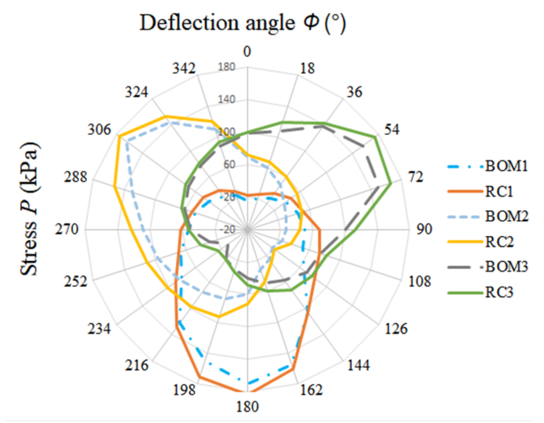
The stresses on the connection plate when the manipulator is bent in different directions are obtained by substituting the air-pressure values in different chambers into Equation (9). In
Figure 8, BOM1 represents the stress value between the flexible connecting plate and the chamber numbered 1, RC1 represents the stress value between the rigid plate and the chamber numbered 1, etc. When the soft arm was deflected in the range of 0–360°, the air pressure in the three chambers constantly changed and was not equal. For each 18° deflection of the manipulator, we recorded the air-pressure parameters of three chambers of a group of manipulators and recorded 20 groups of data in total. The data are shown in
Table A1 (
Appendix A). Based on the results, we considered the influence of stress from the BOM and RC connecting plates under different deflection angles of the manipulator.
When the bending angle was , we determined the change in stress for three CFs of the connecting plate to different deflection angles through some experiments. In the graphic, the connecting plate RC was subjected to a maximum stress of about 180 kPa, while the connecting plate BOM was subjected to a maximum stress of about 170 kPa. Under the same deflection angle, we can see that the stress on BOM is always smaller than the stress on RC. This result means that the stresses is less concentrated on BOM.
For the flexible pneumatic manipulator, the mapping of air pressure to motion space can be obtained by deriving the relationship between the variation in pressure and the curvature. Combined with the moment-balance equation, the bending curvature of the individual module of the manipulator can be derived from the radius of the chamber-bending curvature; then, the relationship between the curvature
k and the air-pressure parameter
P can be known:
where
is the elongation ratio of the chamber along the axial direction. The maximum inflation air pressure of the bending chamber is 170 kPa, and the deflection angle is
. The maximum elongation ratio of the manipulator is known. The total stress in the module is constant, but the stress-concentration-effect coefficient varies with the deflection angle. Using the total air pressure
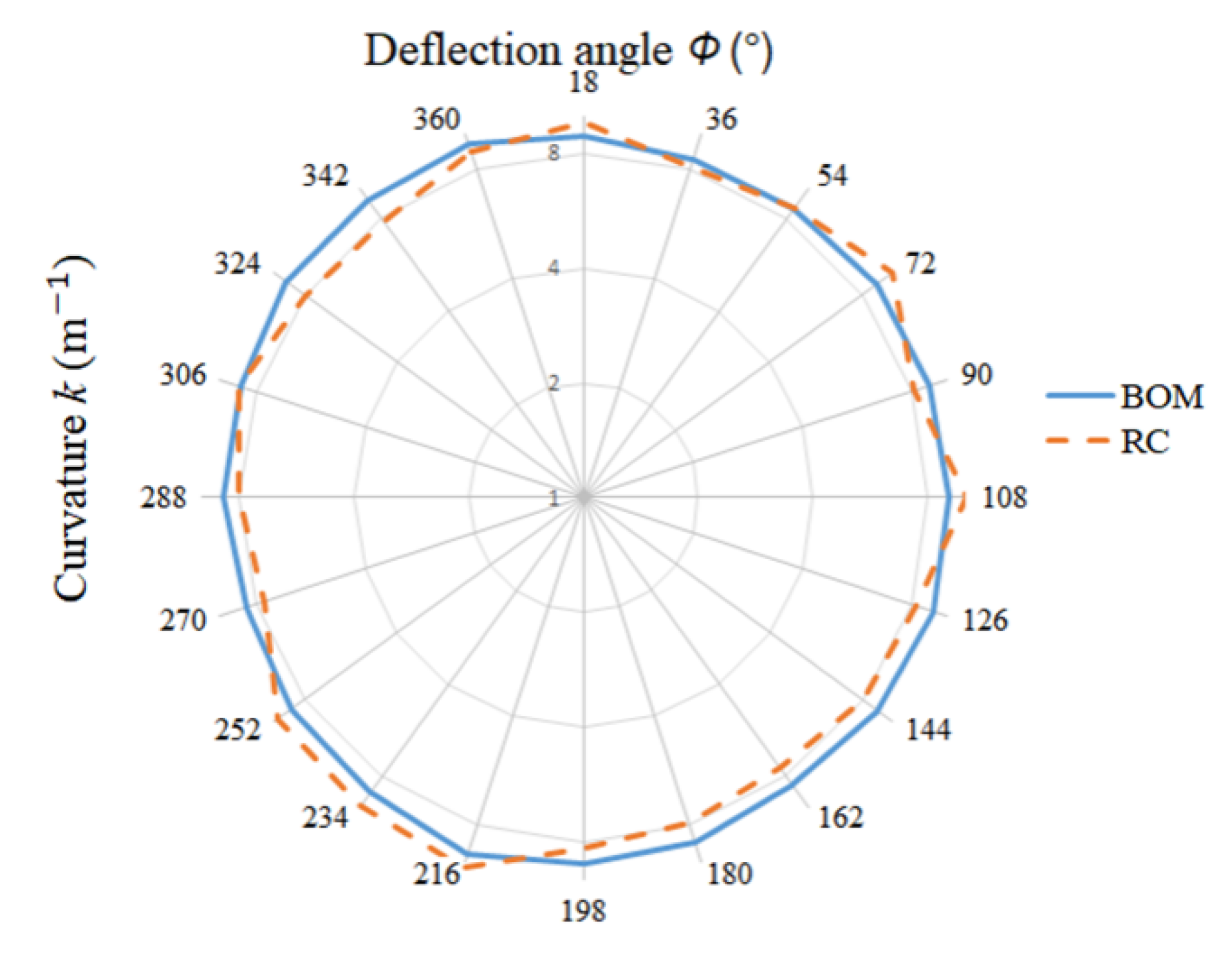
P of the bending chamber as the variable, the bending variation law of the module at each deflection angle is fitted to determine the variation range of the maximum bending curvature. In this paper, 24 angles were selected on average among various deflection angles, and the actual maximum bending curvature of the module was deduced by combining the measurement results. BOM represents the curvature of the module assembled with a flexible connection plate, and RC represents the curvature of the module assembled with a rigid connecting plate. The results are shown in
Figure 9.
It can be seen that, under the same air-pressure input conditions, the bending curvature of the manipulator assembled with the BOM plate changes in the range of 8.5 m−1~9.6 m−1 while the bending curvature of the manipulator assembled with the RC plate changes in the range of 7.5 m−1~10.4 m−1. RC is not as stable as BOM during the movement, which is caused by the poor stress-transfer characteristics of the rigid connection plate.
5. Experiments
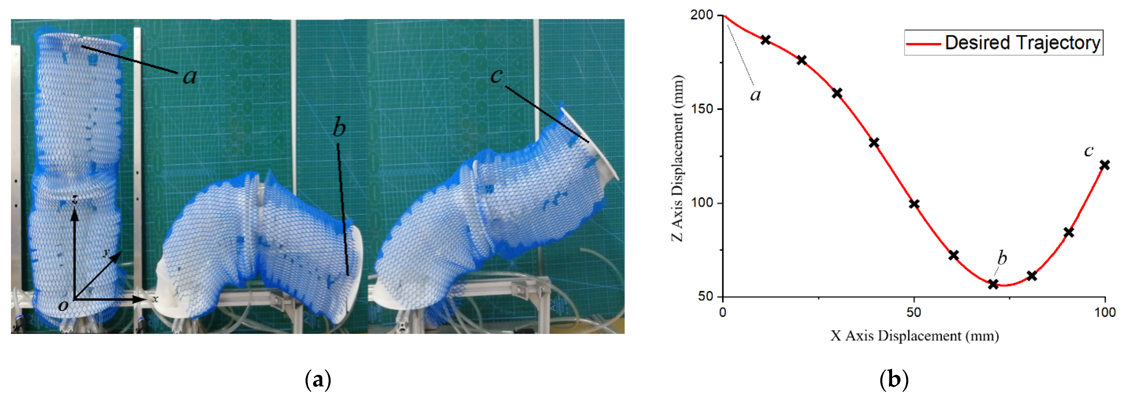
In this paper, a flexible pneumatic manipulator assembled with two modules was used for the bending experiments to analyze the effect of different materials and structures of the connecting plates on the motion performance of the manipulator. To verify the enhancement of the flexible connection plate on the motion control effect of the manipulator, we demonstrated the flexible motion of the robotic arm in a trajectory planning experiment. In our experimental setup, the bottom of the manipulator was fixed on the experimental platform, and the manipulator was vertical along the positive z-axis direction at the initial moment. Given the desired motion trajectory “V” of the flexible manipulator, as shown in
Figure 10b, we selected 10 observation points using a fork in the desired trajectory to analyze the motion error of the manipulator. Points a, b, and c in
Figure 10a represent the position of the manipulator observation point at the initial state, the manipulator moving toward the lowest position, and the manipulator in the most complex position of stress.
Table A2 is the coordinates of the experiment.
We used an experimental platform consisting of a control system, a stopwatch for recording the run time, and a visual device for detecting the position information to verify the motion of the soft manipulator. The method used to obtain the coordinates of the robot arm is as follows: we used a binocular vision camera to obtain the depth information of the center point at the end of the manipulator. The difference between the two viewpoints was first calculated and a distance estimate was established, which was combined with an obstacle detection algorithm to return the coordinates of the object. Then, the coordinates of the observation point O’ in the Cartesian coordinate system were obtained utilizing a positional transformation matrix. During the movement of the manipulator, the air pressure provided through the driver ranged from −80 kPa to 180 kPa. The driver ACU-MMN we used was from Suzhou Rochu Robotics Co., Ltd, Suzhou, China.
First, we analyze the arc length variation during the movement of the manipulator. The manipulator moves to the set node position in a smooth state within 10 s. According to the set conditions, the total arc length of the manipulator at the node in the initial state is
L = 200 mm. The sum of the arc lengths of the manipulator is the main studied object
L = L1 +
L2, and the data displayed by the pressure gauge is recorded in 1 s time steps in the experiment. The actual arc length change and pressure are collected to analyze the effect of different connecting plate devices on the robot drive space and configuration space. In
Figure 11, RC represents the arc length variation during the motion of the manipulator equipped with a rigid connecting plate, while the arc length variation curve of the manipulator equipped with BOM is obtained by fitting the actual data with a three-time polynomial, where the arc length variation in BOM ranges from 175 mm to 205 mm; the arc length variation range of RC is between 166 mm and 209 mm. We also recorded the velocity and acceleration data during the motion of the manipulator and noted that the movement speed of the RC-equipped manipulator is approximately the same as that of the BOM-equipped manipulator. Specifically, we controlled the movement speed of the pneumatic arm by controlling the gas flow rate in the delivery tube, which is achieved by controlling the switching speed of the solenoid valve of the active driver. The velocity
v of the manipulator was kept within the range of 0~25 mm/s, and the acceleration
a was also kept at a low value in the range of ±10 mm/s
2, which indicates that the manipulator moves slowly and smoothly to minimize the impact caused by system disturbances. From the experimental results, it is easy to analyze that the motion curve of the manipulator with the flexible connection plate is relatively smooth, which also means that the system is relatively stable.
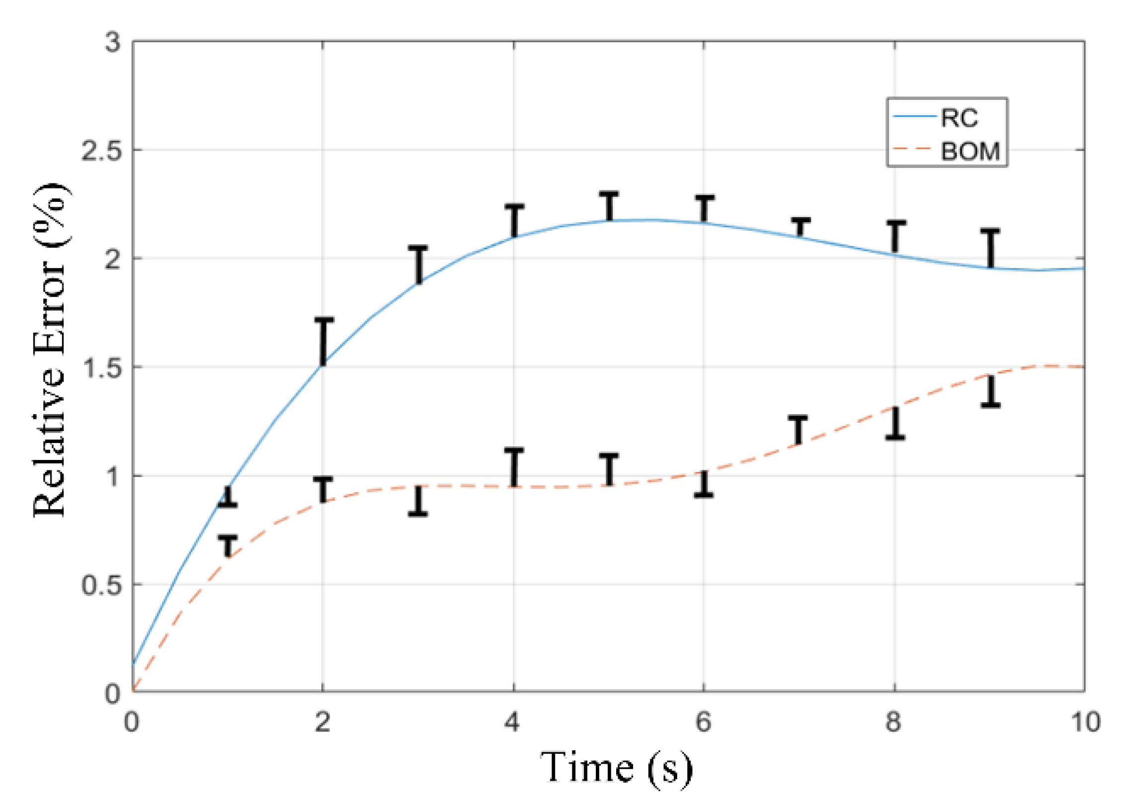
Then, we compare the motion error of the two groups of manipulators. The coordinate information of the desired trajectory is substituted into the inverse kinematic algorithm of the manipulator, and the result was input into the control strategy of the soft manipulator to achieve an intuitive solution for trajectory tracking, which is limited by the computational efficiency of the kinematic algorithm, and the process is not in real time. We tested the soft manipulator with a flexible connection plate and with a rigid connection plate and recorded the coordinate information of each group of manipulators during the experiment to analyze the performances of both. The relative error (
RE) is calculated as follows:
where
is the actual coordinate vector of the observation point and
is the coordinate vector of the set point,
. Note that each group of the BOM and RC experiments was repeated three times separately, and the three groups of relative-error results obtained from the experiment were averaged and plotted in
Figure 12.
Comparing the two group relative-error data, the RC-equipped manipulator exhibited a higher relative error during its motion. In particular, the stress distribution of the connecting plate is the most complicated when the two segments of the manipulator are bent in different directions. Connecting these calculations with a smooth curve, we also mark the differences between the actual coordinates of the observation points and the theoretical values in
Figure 12, and the lengths marked in black represent the degree of deviation.
The experimental results show that, with an increase in time, the motion error of the manipulator with the rigid plate accumulates continuously, while the motion error of the manipulator using a flexible plate is kept at a low level. The results of the control experiments are compatible with the results derived from the theoretical analysis. Thus, the flexible connection plate proposed in this paper is validated for improving the soft manipulator’s motion accuracy.
6. Conclusions
In this paper, a new flexible connection plate was proposed for a pneumatic continuum flexible manipulator, inspired by the soft connection property of the oblique muscle layer of the octopus arm. Compared with the existing rigid connection plate, our design takes into account the driving moment generated by a single chamber on the connection plate. By applying a flexible silicone material instead of the traditional rigid material to make the connection plate, the flexible manipulator can achieve continuous flexibility in tandem form, thus improving the stress concentration phenomenon of the connection plate.
According to the characteristics of the multi-segment module bending motion of the manipulator, we introduced the Naiver and Legendre function models to analyze the influence of the total stress of each bending chamber coupling on the stress concentration of the connection plate in the modeling process.
According to the experimental results, the average stress on the chamber connection module in the flexible connection plate is about 15 kPa smaller than that of the rigid connection plate. During the motion of the flexible robot, the flexible design of the connecting plate can prevent more stresses and strains from being transferred to other components and can reduce the error during motion by about 1%. This helps the flexible pneumatic robot obtain an advanced flexible design, and a multi-segment structure with better motion accuracy and mechanical properties.
In our future work, we will aim to build more accurate kinematic models to describe the state of the flexible robotic arm during its motion and will implement exploration and flexible grasping functions in a constrained environment.


