1. Introduction
Thanks to the development of AI technologies in recent years, simple tasks can be done by computers. As a result, tasks that are too simple and time-consuming for humans are being done by computers. One such task is motion monitoring/surveillance, as it is inappropriate for a human to manage and monitor multiple CCTVs because it requires a long period of concentration. With the advent of automated surveillance systems, several algorithms have appeared in automated detection.
Examples of automated surveillance systems include systems that detect falls [
1] or the gait of passers-by [
2]. Each of these systems is based on its own movement detection algorithm, some of which are based on pose estimation models. The pose estimation model has weaknesses such as natural error and detection error, which can make the false movement of the target user’s joint point regardless of the target user’s actual movement. This weakness does not usually make a problem because the amount of such error is small enough to deal with large movement from some distance. However, it can cause a problem in dealing with a slow-moving target at a near distance.
In this study, to enhance the effectiveness of smart mirrors for the well-being of the elderly, we attached a camera to a smart mirror system that detects the movement of the elderly at a near distance. In this case, the elderly can often make slow motions and motion detection is made at a near distance. Therefore, the weakness of the motion detection system made by natural error becomes critical.
As the human lifespan and the population of the elderly are continuously increasing [
3], the detection of slow-motion should not be overlooked. The population of the elderly age group is growing at a faster rate than other age groups [
4]. Our study aims to implement a health management system for the elderly with consideration for their lack of mobility. In [
5,
6,
7], the authors suggest that regular exercise, such as a national exercise program, could have a positive impact on their health, especially for the elderly. However, as their physical ability declines, it is recommended that they should avoid strenuous exercise [
8]. Moreover, as humans age, their mobility and speed tend to decrease. In [
9], the mean gait speed of men aged 40 to 49 years was 143.4 cm/s, whereas, for women aged 80 to 99 years, the mean was 94.3 cm/s. Thus, targeting movements in the proposed system mainly includes walking and a national exercise program and excludes single joint movements such as lifting dumbbells.
By increasing the motion detection threshold, natural errors could be easily resolved, but another problem occurs when detecting slow movements by traditional methods, which use a threshold value to detect movement. If a target user’s speed is too slow, the motion may not be detected. In this study, dealing with such a problem is our goal. The Smart mirror environment will be explained in
Section 3 and the proposed algorithm will be introduced in
Section 4. Experiments on the weaknesses of the previous pose estimation model and the effectiveness of the proposed method will be presented in
Section 5.
2. Related Work
2.1. Use of Smart Mirror
IoT technology is receiving a lot of attention, and many technologies are being developed [
10] and widely used such as UAV [
11]. The Smart Mirror is one of those Internet-of-Things (IoT) devices made by inserting a board such as a mini PC into the basic structure of a mirror. Depending on the purpose, a display and speaker can be used as a visual and audio output device, and various visual, tactile, audio, or other sensors–such as RGB camera, RGB-D camera, touch panel, microphone, or RFID sensor–can be inserted as an input device [
12,
13].
Examples of roles suggested in a thesis that focused on the utility of smart mirrors [
14] include information delivery and entertainment. An example of a smart mirror used as a window for information transmission is a smart mirror that acts as a secretary [
15], such as delivering daily information in a bathroom, and a smart mirror that can be used for academic purposes [
16], in this case, anatomy.
Smart mirrors used to transmit information are also called magic mirrors. In Blum et al. [
16], magic mirrors were used for learning anatomy. By processing visual input of the target user through an RGB-D camera, that system can show estimated 3D models of organs in the user’s abdomen region, text information, and additional reference images about anatomy. Seraku et al. [
15] designed a bathroom smart mirror that estimates the weight of the user and displays simple information such as mail, weather, and calendar in the bathroom.
As mirrors are essential furniture in the home, smart mirrors are easier to access than any other IoT device, and this is no different for elderly households. Considering that it is a fixed mirror, a smart mirror with an RGB camera can play the role of a surveillance system similar to a CCTV surveillance camera. In this case, a system that detects the safety of the elderly or a slow-motion detection system that allows one to exercise while watching is more appropriate than a CCTV system that detects pedestrian movement or monitors the presence of a suspicious wanderer.
2.2. Movement Recognition and Pose Estimation
In [
1], the authors introduced an algorithm for quickly judging elderly falls using an algorithm that extracts the target’s skeleton with OpenPose, measures the speed of the center of the hip joint, and calculates the angle with the ground.
The content introduced in [
2] is the skeleton-based gait detection algorithm, an algorithm that determines through image input whether a target’s gait is abnormal. In this algorithm, the skeleton information for the target is extracted using a depth sensor such as Kinect, and seven angles of skeleton coordinates, excluding the upper body, are feature-extracted. The extracted vectors are converted into codewords using a clustering technique. During detection, if the gait cycle is less than a threshold, it is judged as an anomaly.
In [
17], the authors introduced a pedestrian detection algorithm that uses two consecutive frames to determine the direction of pedestrian movement. It calculates displacement in five directions through comparison with the previous frame, learns the detector based on pattern recognition using Adaboost, and then performs an experiment to detect the motion and appearance of pedestrians.
In addition, there is a simple method for distinguishing whether the target in the current frame is moving/stopped. It is called the “frame subtraction method” [
18] and “two-frame difference method” [
19]. In this paper, it will be called the adjacent frame subtraction method (AFSM) as well. The AFSM simply calculates the difference between two adjacent frames and checks if the difference value is above/below the movement threshold. Those papers used AFSM with their own pre-processing method.
In [
19], the authors performed gray variation as pre-processing and subtracted odd-even frames or background-current frames with the AFSM. In [
18], the authors used AFSM as a fundamental detection method, but their objective was to find a better threshold value by using canny-edge detection and the Otsu method [
20]. The AFSM itself was not their main point; however, our point is to understand the weakness of the AFSM and to find a better method.
In [
21], an algorithm for crime prevention that quickly detects with a small error the presence and movement of a person were introduced. It stores the static background that CCTV captures continuously and identifies the existence of a specific object when the difference between the static background and the current image frame is less than 95%. The skeleton information of the identified entity is calculated, and when the displacement of the skeleton coordinates in the previous frame is greater than the absolute value of the threshold, the movement and direction are determined. It uses fixed CCTV cameras and skeleton information, and it detects the displacement of the skeleton relative to the previous frame.
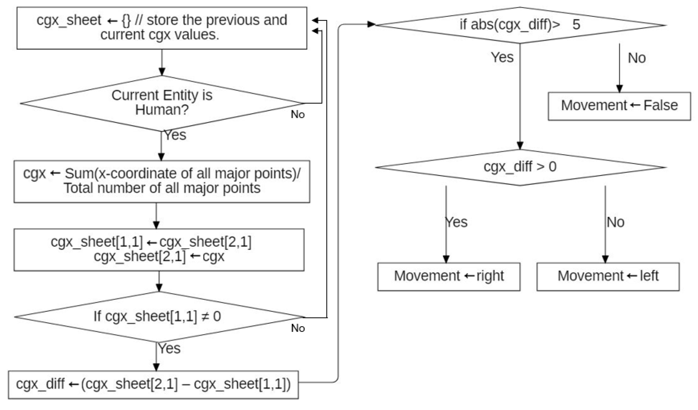
The center gravity method (CGM) is an algorithm proposed [
21] for judging whether the movement is less than a threshold using skeleton information. The center gravity coordinates obtained by averaging the coordinates of all skeleton points are calculated, the displacement between previous/current frames of the center coordinates is calculated, and the result of whether the displacement is less than or greater than the threshold is obtained. In that study, the original background removal work and the method for measuring change in the x-coordinate is much faster. We will use only the motion detection method in the experimental section.
Figure 1 shows a flowchart of the algorithm.
3. Environment for Smart Mirror
Movement detection algorithm for a surveillance system generally targets for the fixed camera, but general CCTV with a high stand is not good enough for small movement detection because of its special viewing angle and limitations of the skeleton-based pose estimation model. For small movement detection, it is more suitable to use a fixed camera installed height of eye level and having a similar viewing angle to the general human eye’s field of view. Smart mirrors can meet this condition.
A smart mirror has good expandability and can include a module on the basic mirror foundation. A display can be inserted under the glass to give visual feedback, or a voice module can be mounted to give voice feedback. In addition, input sensors such as a touch panel, general RGB camera, RGB-D camera, and RFID sensor can be inserted to perform various functions. In this study, it is assumed that an RGB camera (webcam) is used as the input device for the smart mirror.
In an algorithm that detects motion based on the coordinates of the previous frame, it is unlikely that the displacement per frame of the moving object is less than the natural error unless the object is too slow or the natural error is too large. However, if the object is an elderly person with limited mobility, the movement of the object is unstable and slow, and if the pose estimation model used by the algorithm is unstable, a large tolerance value must be used. In such an environment, the method presented in this paper is advantageous.
4. Movement Detection Algorithm for the Elderly in Smart Mirror
4.1. Overall Structure of Movement Detection System
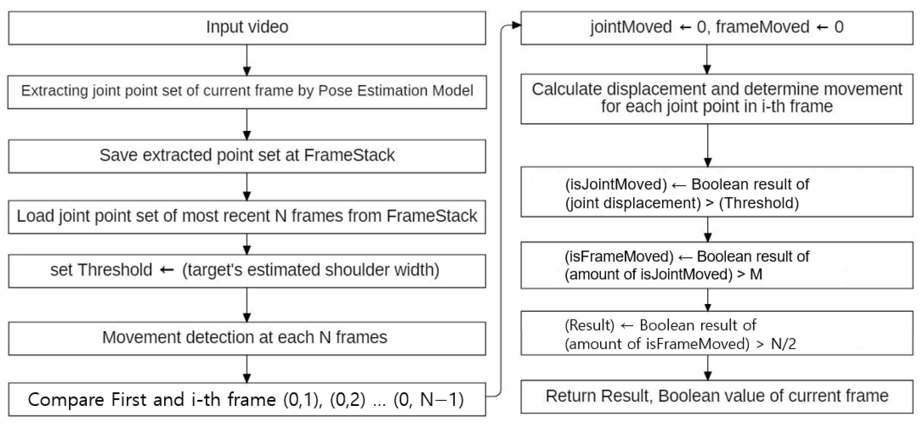
The motion detection method in this study uses the displacement of the joint coordinates. Calculating the displacement is not limited to two adjacent frames but uses more previous frames (frame depth, ‘RecentFrame’). If the corresponding displacements are greater than 0 (which is the threshold value), it may be determined that the corresponding frame is in a moving state; otherwise, it may be determined that they are in a non-moving state. However, due to the existence of natural error, which will be described later, the threshold value cannot be set to 0. And due to the existence of detection error, which will be described later, movement detection should be determined not by single frame result but by the majority result of recent frames. In
Figure 2, overall structure of movement detection system in the proposed study is described.
The algorithm that used a fixed threshold value might have a potential weakness for movement with varying distances, like the movement towards the camera. So, as the threshold value must vary with distance, the shoulder width of the current target is set as a threshold value. Different threshold standards may be selected according to the purpose of the system. In this system, detecting the presence of minor movement in a smart mirror is the purpose.
The pose estimation model has some limitations. The limitations of the pose estimation model hinder movement detection. The limitations will be discussed in the next session. The system in this study aims to overcome the pose estimation model’s limitations for movement detection.
4.2. Pose Estimation Model and Its Limitation
As shown in
Table 1, There are two general limitations of a skeleton-based pose estimation model and another limitation in movement detection that uses the pose estimation model.
- (1)
Natural error is a small error that occurs in a stopped situation. When a target is static, all of the target’s joint points are moving a little. This is a basic limitation of the pose estimation model; in this study, non-intentional movement will be included as a natural error. Non-intentional movement is negligible physiological movement, such as breathing action.
- (2)
Detection errors are divided into two types, (2-1) whole point error and (2-2) partial point error. A whole point error is an error in which all the point’s coordinates are wrong, whereas a partial point error is an error in which the coordinates of a single or a couple of points are wrong.
- (3)
Slow movement can be detected as a movement if the threshold is set very low, but then the system may miss ignoring the natural error and detect movement in a stopped situation. We manage these errors in this session.
The problem with the current model is that the points move even when a person is in a stationary state and there are several types of detection errors. There are several reasons why a point moves even if the subject stands still. First, it is difficult to specify a single joint coordinate in that joint area. For example, it is not possible to accurately specify the wrist coordinate in the wrist area. Because the image changes slightly with every frame, the coordinates of the representative joints are not fixed, but they are definitely present in the joint area. Second, it is a dilemma in a human motion detection system. Consider a robotic police officer saying “freeze” to a suspect who is raising both hands in surrender. Should the system detect the unintended micro-movement of an arm tremor as a movement even if the target keeps freezing? Humans may try to stay motionless but cannot stay strictly motionless as they breathe.
Pose estimation has another problem in detecting targets. It is an accuracy performance issue for the pose estimation model. Detection error can be divided into two types, as shown in
Figure 3: whole point error and partial point error. A whole point error is an error in which all the point’s coordinates go wrong. A partial point error is an error in which the coordinates of a single point, or a couple of points are wrong, while the other points are in a tolerable place. Whole point error does not appear sequentially or frequently, while point error appears in almost every frame of a video with a high error rate.
In the current system, Movenet [
22] is used as a pose estimation model. Its detection error rate was below 15% per frame for the whole point error and less than four joint points per frame for partial point error. Movement detection in the proposed system includes walking and basic freehand exercise for the elderly. As we excluded such actions, which were only single-joint moves, the following method will not encounter such a problem. In addition, using the majority result of recent frames may be a solution for managing whole point error.
4.3. Traditional Movement Detection Method and Its Limitation: Slow Movements
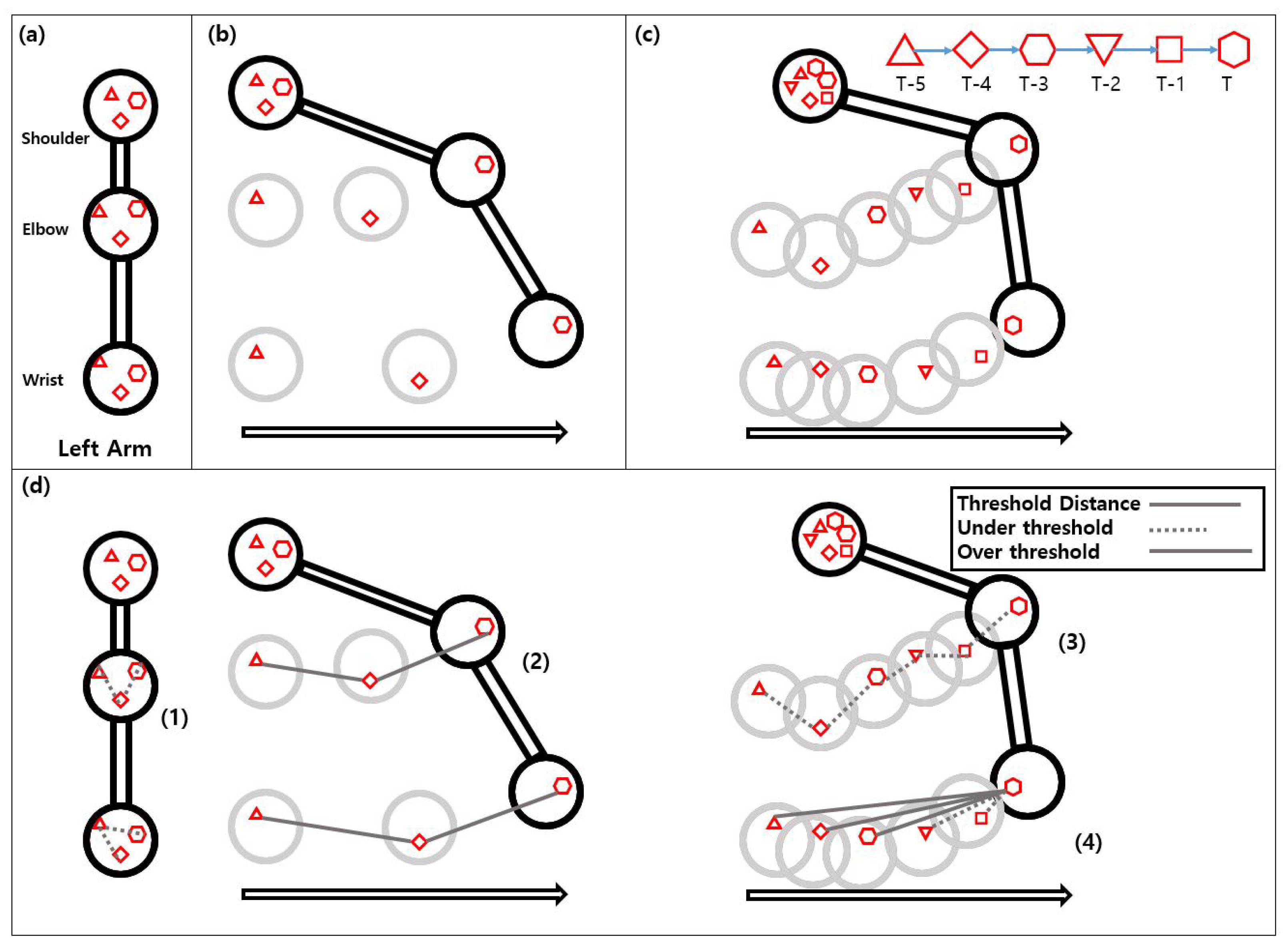
Figure 4 shows skeleton point of arm, natural error in stationary state (a), normal movement (b), slow movement (c), and movement detection methods (d). The moved distance in (b) and (c) is the same, but the speed is different. In
Figure 4d, the threshold value for the movement detection algorithm is shown in the upper right box. Each shape represents a locus of each point through a 3 and 6-frame trajectory. Each line represents joint displacement. Displacement greater than the threshold is shown in solid line while displacement less than the threshold is shown dotted.
The traditional method of distinguishing circumstances between
Figure 4a,b is simple. Using AFSM, we compare the amount of movement and determine whether it is less/greater than the threshold. In
Figure 4a, the points generated from standing still have very small displacements. On the other hand, in
Figure 4b, the displacement of each moving point is very large. That is, if the movement distance (displacement) of each point is smaller than the threshold, it can be determined that the subject is in a stopping state, and if it is larger, it can be determined that the subject is in a moving state. In many studies, even if the goal of the algorithm is different (movement detection, fall detection), adjacent frames are compared.
Scenarios and formulas are given below in
Figure 5. This simple method has often been used in combination with other pre-processing methods, such as in [
18,
19,
21]. Displacement of joint at each frame (
) is compared with threshold to return boolean value whether it is less or more, through frame depth. As we use the majority result of recent frames for handling detection error, the variable ‘Moved’ and ‘Stopped’ is counted based on the method’s return value.
We can use the maximum of the natural error extracted from the ideal stationary video as the threshold value of the equation (Equation (
3)). An ideal stationary video is a video in which the posture of the target is clearly fixed and there is no detection error (Equation (4)). Examples of detection errors include the presence of a single point in an abnormal location or the detection of another object in the background as a human. Under these conditions, the natural error is a set that have elements as the size of all
in the stationary video. However, calculating the threshold in this way is inappropriate, as detection may occur for every target. Furthermore, simply increasing the threshold could be a solution for dealing with natural error. However, this would cause another problem for slow motions. We will explain such a case next.
Unlike the circumstances shown in
Figure 4a,b, the amount of movement is not large in
Figure 4c. As the subject moves very carefully or very slowly, it is definitely moving to the right in general, but the movement distance between frames is often smaller than the threshold. As a result, in this case, AFSM would not work correctly. If the threshold is set lower, it may detect the target’s slow movement as true, but the static target may also detect false movement too, as the natural error would also be greater than the threshold. On the other hand, if the threshold is set higher, it may not detect the static target as a false movement but may miss the target’s slow movement. Moreover, if the natural error is large or the movement is slow, distinguishing between the slowly moving target and the static target will become more difficult.
4.4. Vector Sum Method for Solving Limitations
Looking at
Figure 4c and
Figure 6, the amount of movement is insignificant even when the hexagon and the inverted triangle (
in
Figure 6) in the shoulder area are compared, but the distance between the hexagon and the triangle (
) is very large, even though the distance between the triangle-rhombus and the rhombus-hexagon is small in the wrist figure. Therefore, if one compares the magnitude of the vector sum moved several frames in a row instead of making a one-to-one comparison with the previous frame, it would be acceptable to set the threshold somewhat higher. This method is called the Vector Sum Method (VSM). Formulas are given below
Figure 6.
In expression (
5), sum of displacement of joint at each frame (
) is compared with threshold to return boolean value whether it is less or more, through frame depth. In expression (6), as we use the majority result of recent frames for handling detection error, variable ‘Moved’ and ‘Stopped’ is counted based on the method’s return value.
Even if vector sum is used for displacement, using VSM is different from just downsampling all the frames because the downsampling method is faulty in the case of periodic motion.
Figure 7 shows 5 coordinates moving to the right and coming back. This case is detected as a movement by the vector sum method, as
,
is greater than the threshold. However, if downsampling occurs by calculating only the initial-final coordinates (
), the final displacement will be smaller than the threshold, as shown in the figure (
< Threshold).
The rationale for using this method is that negligible movements—natural error, changes according to physiological movements—have no direction, so there is no difference between the change between frame t = 1 and t = 600, whereas if there is a movement, even if the difference is insignificant, difference continues to increase, as shown in
Figure 8. Even if the movement is slow, the size of the sum of vector through N frames increases maximally N times, so if the movement is intentional, the threshold can be amplified.
However, the VSM also has limitations. Because the information of past frames has to be compared, the memory will be increased. Additionally, compared with the ASFM, where only the previous coordinates were compared and calculated, the computation will be increased as well. In addition, there is a possibility that the slower the object, the larger the value of frame depth is needed.
In addition, there is another limitation to this detection method. This algorithm cannot increase the threshold and frame depth too much. This is an issue of periodic motion. Intentional movement assumes that there is a direction for a very short time, no matter how irregular, as long as the person intends it. For example, if we specify case 1 (frame depth of 0.3 s, a threshold value of shoulder width) and case 2 (frame depth of 1 s, a threshold value of about twice the width of the subject’s shoulders) in a scenario where the subject shakes their arm rapidly, the motion of randomly shaking the arm will be classified as a movement in case 1, but will be misclassified as a natural error in case 2.
5. Experimental Results
5.1. Experimental Setup
5.1.1. Overall Setup
We prepared three types of experimental data. The threshold value used for the experiment was equal to the user’s shoulder width and the previous frame to be compared (frame depth) was 10 frames. The camera was fixed and the distance between target and camera was 2 m. In each scenario, the user was looking at the camera consistently. The movement range is limited to the camera’s viewing angle. The experimental environment was indoors. The frame rate was 30 frame/s. The resolution was 640 × 480 and the camera used was a Logitech C922 Pro Stream 1080p.
Motion is detected using the prepared data in a method based on three algorithms for each frame. (1) The first algorithm is a center gravity method (CGM) that compares only the previous center point coordinates, as shown in
Figure 1. (2) The second algorithm is an adjacent two-frame method (AFSM) in Equations (
1) and (2) and
Figure 5, a movement comparison method that compares only the previous frame. (3) And the last algorithm is a vector sum method (VSM), a method for comparing each of the coordinates of the several previous frames, in Equations (
5) and (6) and
Figure 2.
The data are classified as fast-moving vector scenarios (FMV Scenario), not moving vector scenarios (NMV Scenario), and slow-moving vector scenarios (SMV Scenario). If the main target is not moving, the data are classified as the NMV scenario. Else, if the main target’s overall movement is less than the threshold, the data are classified as an SMV scenario. Else, the data are classified as FMV scenarios. In movement scenarios, comparing data only differs in speed.
The purpose of experimenting SMV scenario is to show that the proposed method could handle slow movement issues. By using the newly proposed method (VSM), a movement that previously used methods (AFSM, CGM) could not detect must now be detected successfully. The purpose of experimenting with FMV and NMV scenarios is to show that VSM does not have an over-fitting issue. By using the newly proposed method, a movement that the previously used method could detect must be detected successfully as well.
In Experiment 1, we input three types of data and collected movement detection results at each frame. Each method returns the movement detection result as “moved (1)” or “not moved (0)” at a single frame. In FMV and SMV scenarios, the ground truth of each frame is ‘moved’ while the ground truth of each frame is ‘not moved’ in the NMV scenario.
Furthermore, Experiment 2 is planned to measure the displacement of every point between adjacent two frames and calculate the average. The purpose is to show that although it is easy to distinguish between natural error and fast movement by comparing adjacent two frames, it is difficult to distinguish between slow movement and stationary state by comparing adjacent two frames.
5.1.2. Data: Scenarios for Experiment
Each scenario has 15 video sequences. The scenario between FMV and SMV only differs in speed while others are all the same. Speeds in FMV scenarios are 3∼5 times faster than speeds in SMV scenarios. Speed is set based on the elderly’s physical ability. Speed is controlled by controlling time and fixing distance. The NMV scenario is divided by low/high error, based on their error rates. All ground truth values in the FMV and SMV scenario’s frame are ‘moved(1)’, while all ground-truth value in the NMV scenario’s frame are ‘not moved(0)’. Each scenario is described in
Table 2.
5.2. Result of Experiment 1
The result of all scenarios is represented in
Table 3. In a single video, the detection rate is calculated by (number of frames the method returned as ‘moved’)/(number of total frames). In the FMV and SMV scenarios, as the ground truth value of each frame is “moved (1)”, methods must record a higher detection rate while it must record a lower detection rate in the NMV scenario. Each cell represents the average/standard deviation value of each scenario, which contains 15 video sequences.
In FMV scenarios, the detection rate increased to 10∼30 percentage points between AFSM and VSM. In SMV scenarios, the detection rate increased greatly above 50 percent point between AFSM and VSM. It is presumed that the reason for the low detection rate in the FMV scenario of CGM and AFSM is that we set the threshold value too high. However, even with this high threshold value, the detection rate of VSM was quite successful. In the next experiment, the reason why we cannot set the threshold value lower will be shown.
5.3. Result of Experiment 2
Table 4 reports the average/standard deviation of the mean displacement of whole points and threshold in the video. The purpose is to show that although it is easy to distinguish between a stationary state and fast movement by comparing adjacent two frames, it is difficult to distinguish between a stationary state and slow movement by comparing two adjacent frames. All units of measure in the table are pixels.
Joint point displacement is around 10 pixels in FMV scenarios, around 4 pixels in SMV scenarios and around 1.5 pixels in NMV scenarios. However, in the “Standing-High Error” scenario, its displacement is around 4 pixels. This means the distinction between the target’s slow movement and natural error is difficult in a particular video.
In the current experiment, the threshold is set to the target’s shoulder width and its shown to 7∼9 pixel. With this high threshold and method that only compares threshold and displacement between two adjacent frames (AFSM, CGM), the natural error in the NMV scenario is detected as ‘not moved’ but the target’s slow movement is detected as ‘not moved’ too. If the threshold is set lower (as half of the current threshold), the target’s slow movement will be detected as ‘moved’ but a natural error in the NMV scenario would detect as ‘moved’ too. By using VSM, the threshold is set high, natural error in NMV scenario is detected as ‘not moved’ and target’s slow movement is detected as ‘moved’.
6. Conclusions
This paper presented a skeleton-based motion detection algorithm using MoveNet, which is a TensorFlow AI model, as a pose estimation model. We analyzed and experimented with the limitations of the pose estimation model, MoveNet, and the problems of algorithms that determine something by comparing between two adjacent frames. In addition, we showed that such problems can be solved by comparing the information from the previous frames.
Moreover, to cope with the elderly’s slow movement in a fixed camera environment, it is necessary to distinguish between slow movements and natural errors. The method of distinguishing between slow movements and natural errors is based on the adjustment of threshold values. Reducing the threshold value requires a higher accuracy or more stability of the artificial intelligence model that can make the natural error itself smaller. Increasing the threshold value requires the distinction between slow movement and natural error. In this paper, the latter was chosen as the performance enhancement of the artificial intelligence model requires a high cost.
The limitation of the proposed algorithm is that it requires fine-tuning of the variables. The threshold value, based on shoulder width in the proposed study, must be set differently if the target is not facing the mirror. The frame depth must be set differently if the input video’s frame per second differs. If frame depth is set too large, the problem of periodic motion occurs, and computation time is increased.
For future work, a method by which frame depth variable could be automatically adjusted based on the frame per second of input video or based on target movements is needed.
Author Contributions
Conceptualization, B.-S.Y. and J.-W.J.; methodology, B.-S.Y. and J.-W.J.; software, B.-S.Y. and J.-W.J.; validation, B.-S.Y., T.-W.K., Y.-S.C. and J.-W.J.; formal analysis, B.-S.Y. and J.-W.J.; investigation, B.-S.Y. and J.-W.J.; resources, B.-S.Y., T.-W.K., Y.-S.C. and J.-W.J.; data curation, B.-S.Y., T.-W.K., Y.-S.C. and J.-W.J.; writing—original draft preparation, B.-S.Y. and J.-W.J.; writing—review and editing, B.-S.Y., T.-W.K., Y.-S.C. and J.-W.J.; visualization, B.-S.Y. and J.-W.J.; supervision, J.-W.J.; project administration, J.-W.J.; All authors have read and agreed to the published version of the manuscript.
Funding
This research was partially supported by the MSIT (Ministry of Science and ICT), Korea, under the ITRC (Information Technology Research Center) support program (IITP-2022-2020-0-01789) supervised by the IITP (Institute for Information & Communications Technology Planning & Evaluation), the Ministry of Trade, Industry and Energy (MOTIE) and Korea Institute for Advancement of Technology (KIAT) through the International Cooperative R&D program (Project No. P0016096), the Technology development Program (S3041234) funded by the Ministry of SMEs and Startups (MSS, Korea), the National Research Foundation of Korea (NRF) grant funded by the Korea government (MSIT) (No. 2018R1A5A7023490), and the National Research Foundation of Korea (NRF) grant funded by the Korea government (MSIT) (No. 2020R1F1A1074974).
Institutional Review Board Statement
Not applicable.
Informed Consent Statement
Not applicable.
Data Availability Statement
Not applicable.
Conflicts of Interest
We declare that we have no financial and personal relationships with other people or organizations that could have inappropriately influenced our work, there is no professional or other personal interest of any nature or kind in any product, service, and company that could be construed as influencing the position presented in, or the review of, the manuscript entitled “Error-resistant motion detection algorithm for elderly in Smart Mirror”.
References
- Chen, W.; Jiang, Z.; Guo, H.; Ni, X. Fall detection based on key points of human-skeleton using openpose. Symmetry 2020, 12, 744. [Google Scholar] [CrossRef]
- Nguyen, T.N.; Huynh, H.H.; Meunier, J. Skeleton-based abnormal gait detection. Sensors 2016, 16, 1792. [Google Scholar] [CrossRef] [PubMed] [Green Version]
- He, Z.; Lu, D.; Yang, Y.; Gao, M. An elderly care system based on multiple information fusion. J. Healthc. Eng. 2018, 2018, 4098237. [Google Scholar] [CrossRef] [PubMed] [Green Version]
- Uddin, M.; Khaksar, W.; Torresen, J. Ambient sensors for elderly care and independent living: A survey. Sensors 2018, 18, 2027. [Google Scholar] [CrossRef] [PubMed] [Green Version]
- Sellami, M.; Gasmi, M.; Denham, J.; Hayes, L.D.; Stratton, D.; Padulo, J.; Bragazzi, N. Effects of acute and chronic exercise on immunological parameters in the elderly aged: Can physical activity counteract the effects of aging? Front. Immunol. 2018, 9, 2187. [Google Scholar] [CrossRef] [PubMed] [Green Version]
- Yoon, J.-H.; Kim, C.-H.; Kim, Y.-J. A Comparative Study about Exercise Intensity and energy consumptionin Perfomling National Gymnastics, Gymnastics for Adolescents, Basicand Easy Gymnastics for the New Millenium Health Workout. J. Wellness 2015, 10, 223–231. [Google Scholar]
- Kim, J.-S. Effects of National health gymnastics II(Easy gymnastics) on Elderly People’s Stress, Interpersonal Relationship, Loneliness and Dropout. J. Wellness 2012, 7, 1–12. [Google Scholar]
- Maimoun, L.; Simar, D.; Malatesta, D.; Caillaud, C.; Peruchon, E.; Couret, I.; Rossi, M.; Mariano-Goulart, D. Response of bone metabolism related hormones to a single session of strenuous exercise in active elderly subjects. Br. J. Sport. Med. 2005, 39, 497–502. [Google Scholar] [CrossRef] [PubMed] [Green Version]
- Bohannon, R.W.; Andrews, A.W. Normal walking speed: A descriptive meta-analysis. Physiotherapy 2011, 97, 182–189. [Google Scholar] [CrossRef] [PubMed]
- Forestiero, A.; Papuzzo, G. Agents-Based Algorithm for a Distributed Information System in Internet of Things. IEEE Internet Things J. 2021, 8, 16548–16558. [Google Scholar] [CrossRef]
- Gul, F.; Mir, I.; Abualigah, L.; Sumari, P.; Forestiero, A. A consolidated review of path planning and optimization techniques: Technical perspectives and future directions. Electronics 2021, 10, 2250. [Google Scholar] [CrossRef]
- Athira, S.; Francis, F.; Raphel, R.; Sachin, N.; Porinchu, S.; Francis, S. Smart mirror: A novel framework for interactive display. In Proceedings of the 2016 International Conference on Circuit, Power and Computing Technologies (ICCPCT), Nagercoil, India, 18–19 March 2016; pp. 1–6. [Google Scholar]
- Mittal, D.; Verma, V.; Rastogi, R. A comparative study and new model for smart mirror. Int. J. Sci. Res. Comput. Sci. Eng. 2017, 5, 58–61. [Google Scholar] [CrossRef] [Green Version]
- Besserer, D.; Bäurle, J.; Nikic, A.; Honold, F.; Schüssel, F.; Weber, M. Fitmirror: A smart mirror for positive affect in everyday user morning routines. In Proceedings of the Workshop on Multimodal Analyses Enabling Artificial Agents in Human-Machine Interaction, Tokyo, Japan, 12–16 November 2016; pp. 48–55. [Google Scholar]
- Seraku, C. Smart Washbasin. 2015. Available online: http://smart-washbasin.seraku.co.jp/english/ (accessed on 23 January 2022).
- Blum, T.; Kleeberger, V.; Bichlmeier, C.; Navab, N. Mirracle: An augmented reality magic mirror system for anatomy education. In Proceedings of the 2012 IEEE Virtual Reality Workshops (VRW), Costa Mesa, CA, USA, 4–8 March 2012; pp. 115–116. [Google Scholar]
- Viola, P.; Jones, M.J.; Snow, D. Detecting pedestrians using patterns of motion and appearance. Int. J. Comput. Vis. 2005, 63, 153–161. [Google Scholar] [CrossRef]
- Shi, G.; Suo, J.; Liu, C.; Wan, K.; Lv, X. Moving target detection algorithm in image sequences based on edge detection and frame difference. In Proceedings of the 2017 IEEE 3rd Information Technology and Mechatronics Engineering Conference (ITOEC), Chongqing, China, 3–5 October 2017; pp. 740–744. [Google Scholar]
- Nallasivam, M.; Senniappan, V. Moving human target detection and tracking in video frames. Stud. Inform. Control. 2021, 30, 119–129. [Google Scholar] [CrossRef]
- Otsu, N. A threshold selection method from gray-level histograms. IEEE Trans. Syst. Man Cybern. 1979, 9, 62–66. [Google Scholar] [CrossRef] [Green Version]
- Kundu, M.; Sengupta, D.; Dastidar, J.G. Tracking Direction of Human Movement-An Efficient Implementation using Skeleton. arXiv 2015, arXiv:1506.08815. [Google Scholar] [CrossRef]
- Tensorflow. Movenet. 2021. Available online: https://www.tensorflow.org/hub/tutorials/movenet (accessed on 5 May 2022).
Figure 1.
Center gravity method. Array cgx_sheet is defined to store the previous and current cgx values. Center gravity point, cgx is defined as an average value of all x-coordinate values at a certain frame. The integer variable cgx_diff is defined to calculate differences between adjacent two frames.
Figure 2.
Overall structure of movement detection system in the proposed study. Movenet is used as a skeletal pose-detection model. The Vector Sum Method (VSM), to be discussed in Figure 6, is used as a movement detection algorithm. N represents the parameter RecentFrame in this flowchart. M represents parameters for ignoring single-joint movement, and N/2 represents the majority number of recent frames for detection error.
Figure 3.
Detection errors can be divided into two types. (a): Whole point error is an error in which all point coordinates are wrong. All joint points of the target in (a) are detected in the wrong place. (b): Partial point error is an error in which the coordinates of a single point or a couple of points are wrong. The wrist point of the target in (b) is detected in the wrong place, while the other joint points are detected at a tolerable place.
Figure 4.
Problem with current MoveNet model and representative solution. (a) Natural error in Situation: Stop; (b) Situation: Swing right (moving right in 0.1 s, trajectory of 3 frames); (c) Situation: Swing right slowly (moving right in 0.2 s, trajectory of 6 frames); (d) Comparing solutions: Natural error occurs in (a) and each figure’s shoulder point. Dotted lines and solid lines represent whether the length of line is less/greater than threshold. Shapes(triangle to hexagon) represent locus of each point, as shown in (c).
Figure 5.
Locus of left elbow point (which is represented as a circle). Locus shows as much as before RecentFrame (RF) from the Current Frame. RecentFrame is the frame depth variable, which is 5 in the current figure.
Figure 5.
Locus of left elbow point (which is represented as a circle). Locus shows as much as before RecentFrame (RF) from the Current Frame. RecentFrame is the frame depth variable, which is 5 in the current figure.
Figure 6.
Locus of left elbow point (which is represented as a circle), as much as before RecentFrame (RF) from the Current Frame. RecentFrame is the frame depth variable, which is 5 in the current figure. This figure is from the shoulder area of
Figure 4c.
Figure 6.
Locus of left elbow point (which is represented as a circle), as much as before RecentFrame (RF) from the Current Frame. RecentFrame is the frame depth variable, which is 5 in the current figure. This figure is from the shoulder area of
Figure 4c.
Figure 7.
Locus of returning point (which is represented as a circle).
Figure 7.
Locus of returning point (which is represented as a circle).
Figure 8.
Locus of stopped shoulder and micro-movement of elbow points through 600 frames. Looking at the difference between and , there is little difference in the case of the shoulder, but a very large difference in the case of the elbow. This is general evidence that VSM would detect a natural error in a static target and the actual movements of a target.
Table 1.
Three limitations. Two limitations of the skeleton-based pose estimation model, another limitation in the movement detection system that uses the pose estimation model. Natural error and slow movement are closely related.
Table 1.
Three limitations. Two limitations of the skeleton-based pose estimation model, another limitation in the movement detection system that uses the pose estimation model. Natural error and slow movement are closely related.
| Error Type | Description |
|---|
| Natural error | Small error that occurs in a stopped situation. |
| | Target is static, but all of the target’s joint points are moving slightly. |
| | Non-intentional movement, negligible physiological movement. |
| Whole point error | All points detected at the wrong position. |
| Partial point error | Single/couple of points continuously detected at the wrong position. |
| Slow movements | Target has moved, and its displacement is close to a threshold value. |
Table 2.
Scenario list. Each have 15 video sequences.
Table 2.
Scenario list. Each have 15 video sequences.
| Scenario | Description |
|---|
| (FMV) Walking | Walk towards camera back and forth, 1∼3 m. |
| | Controlled speed to 100∼150 cm/s. |
| (FMV) Freehand Exercise | Squat down and stand up. |
| | Controlled time per action to 2∼3 s. |
| (SMV) Walking | Walk towards camera back and forth, 1∼3 m. |
| | Controlled speed to 33∼50 cm/s. |
| (SMV) Freehand Exercise | Squat down and stand up. |
| | Controlled time per action to 12∼15 s. |
| (NMV) Standing-Low Error | Standing still, no actions. |
| | Detection error rate is less than 3%, Natural error is stable. |
| (NMV) Standing-High Error | Standing still, no actions. |
| | Detection error rate is more than 3%, Natural error is unstable. |
Table 3.
Experiment 1 result for movement scenarios. Each cell represents (average detection rate, standard deviation) through prepared 15 video sequences. Detection rate is calculated by (number of frame which method returned ‘moved’)/(number of total frame) in every single video sequence. Units of measure are percentage.
| Scenario | CGM(%) | AFSM(%) | VSM(%) |
|---|
| AVG | STDEV | AVG | STDEV | AVG | STDEV |
|---|
| (FMV) Walking | 51.15 | 21.05 | 61.27 | 19.92 | 95.31 | 02.82 |
| (FMV) Freehand Exercise | 15.98 | 06.46 | 73.85 | 11.15 | 85.47 | 07.91 |
| (SMV) Walking | 74.83 | 22.05 | 24.13 | 07.51 | 93.43 | 04.24 |
| (SMV) Freehand Exercise | 00.48 | 00.21 | 08.54 | 10.87 | 67.69 | 20.57 |
| (NMV) Standing-Low Error | 01.17 | 02.93 | 00.23 | 00.06 | 01.92 | 03.29 |
| (NMV) Standing-High Error | 40.43 | 38.43 | 06.00 | 08.30 | 04.29 | 02.81 |
Table 4.
Experiment 2 result. Each cell represents (average, standard deviation) of joint displacement and used threshold through prepared 15 video sequences. Each frame has 12 joint points of shoulder, arm, wrist, hip, leg, and ankle. Distance between left shoulder point and right shoulder point is set as a threshold. Each 12 joint displacement is calculated by comparing adjacent two frames. Average joint displacement is the average value of 12 joint displacements and its standard deviation. Units of measure are in pixels.
| Scenario | Joint Displacement (Pixel) | Threshold (Pixel) |
|---|
| AVG | STDEV | AVG | STDEV |
|---|
| (FMV) Walking | 09.55 | 02.93 | 07.79 | 00.67 |
| (FMV) Freehand Exercise | 13.54 | 03.53 | 06.82 | 00.43 |
| (SMV) Walking | 05.14 | 00.71 | 08.29 | 00.29 |
| (SMV) Freehand Exercise | 03.47 | 01.77 | 07.61 | 00.11 |
| (NMV) Standing-Low Error | 01.86 | 00.42 | 09.45 | 00.71 |
| (NMV) Standing-High Error | 04.47 | 01.22 | 07.52 | 02.59 |
| Publisher’s Note: MDPI stays neutral with regard to jurisdictional claims in published maps and institutional affiliations. |
© 2022 by the authors. Licensee MDPI, Basel, Switzerland. This article is an open access article distributed under the terms and conditions of the Creative Commons Attribution (CC BY) license (https://creativecommons.org/licenses/by/4.0/).


