Article

An In Vitro Study of the Reproducibility of the Drilling Access of Digitalized Surgical Guides Generated via Three Different Implant Planning Software Programs

by
Surakit Visuttiwattanakorn
1,* and
Bongkoch Phatthanagowit
2
1
Department of Oral and Maxillofacial Surgery, Faculty of Dentistry, Mahidol University, Bangkok 10400, Thailand
2
Master of Science Program in Implant Dentistry, Faculty of Dentistry, Mahidol University, Bangkok 10400, Thailand
*
Author to whom correspondence should be addressed.
Appl. Sci. 2022, 12(14), 7005; https://doi.org/10.3390/app12147005
Submission received: 16 June 2022 / Revised: 7 July 2022 / Accepted: 8 July 2022 / Published: 11 July 2022

Abstract

:
Several implant planning software programs are widely use in implant treatments, but there has been no evidence of how different software programs affect the accuracy of static surgical guides used for implant placement. Thus, in this in vitro study, we aimed to compare the accuracy of static surgical guides that were prefabricated from three different software programs, including Implant Studio (Program A) (3Shape®, Copenhagen, Denmark), coDiagnostiX® (Program B) (Straumann®, Basal, Switzerland), and Blue Sky Plan (Program C) (Blue Sky Bio®, LLC, Libertyville, IL, USA). A total of 90 drillable polyurethane models were used as samples in this in vitro study; 30 study models were used to plan the same implant positions and design the surgical guides by each software program (n = 30) and then 90 implants were placed in the models using the surgical guides. The outcomes of the surgical guide accuracy were autonomically measured by the evaluation tool in the coDiagnostiX® (Straumann®, Basal, Switzerland) software program. The deviations between the planned and placed implants were automatically evaluated as three-dimensional and angular deviations. The mean three-dimensional implant position deviations from the implant platform of Program A, Program B, and Program C were 0.55 ± 0.25 mm, 0.52 ± 0.31 mm, and 0.56 ± 0.22 mm, respectively. The mean three-dimensional implant position deviations from the implant apex of Program A, Program B, and Program C were 0.72 ± 0.37 mm, 0.73 ± 0.4 mm, and 0.9 ± 0.46 mm, respectively. The mean depth deviations of Program A, Program B, and Program C were 0.19 ± 0.13 mm, 0.31 ± 0.32 mm, and 0.31 ± 0.22 mm, respectively. The mean angulation deviations of Program A, Program B, and Program C were 1.72 ± 0.88 degrees, 2.05 ± 1.24 degrees, and 2.74 ± 1.81 degrees, respectively. The results indicated that there were no significant differences among the three-dimensional positions at the implant platform, the three-dimensional positions at the implant apex, and the depth deviations between all three groups. However, it was found that there was a significant difference in the angular deviation of the implant position between the three groups (p = 0.02). The mean angular deviation of Program C was significantly greater than the Program A group (p = 0.001). In terms of the deviation directions of the implant platform and implant apex for the three groups, most of the deviations of a larger magnitude were toward the mesio-buccal direction. No matter which program was used to plan the implant position, deviations between the placed implant position and the planned position still occurred. Therefore, when planning implant positions with any implant planning software program, one must take into account an implant position deviation.

1. Introduction

An accurate dental implant position is necessary for an implant placement. Conventionally, dental models and radiographic images are used for the diagnostic wax-up, making a radiographic template, planning the implant position, and fabricating a surgical guide. Nowadays, dental implant treatment planning has become more efficient due to the development of digital technology in dentistry, known as computer-assisted implant surgery [1,2].
Computer-assisted surgery for an implant placement, CBCT (cone beam computed tomography) data, and scanning surface data of the overall morphology of the oral cavity are used to generate a virtual three-dimensional structure of the oral anatomical status in implant planning software. This model represents hard tissues, soft tissues, and vital structures that would be advantageous for implant treatment planning. The operators use the acquired data with an implant planning software program to diagnose and plan the implant position following the final restoration or prosthesis to avoid vital structures as well as to generate a surgical guide [3,4,5]. In order to place the fixtures in the correct positions in accordance with the treatment plan, clinicians use a static guidance system, also known as a rigid surgical implant template/guide, to assist them with the procedure [4].
Therefore, it is important to have an accurate implant surgical guide. With the advancement of digital technology in dentistry, implant planning software programs have been developed and play an important role in fabricating these surgical drill guides. Thus, the accuracy of surgical drill guides relies heavily on the implant planning software programs being used. However, no evidence has been found regarding how surgical guides can be affected by the accuracy and reproducibility of different software programs. Hence, we aimed to compare the accuracy of static surgical guides prefabricated by three different software programs.

2. Materials and Methods

2.1. Model Preparation

A total of 30 samples per study group were calculated using the mean values and the standard deviations obtained from a pilot study conducted prior to this experiment. The calculations were performed using the nQuery Advisor software program. Thus, 90 samples were used in this study.
In preparing the study models, a demonstration of a Standard Tessellation Language file (.STL file) of an entire arch with a single-tooth edentulous space at the area of the mandibular left first molar bound by natural dentition was transferred to a three-dimensional software program (Meshmixer™, Autodesk® Inc., San Francisco, CA, USA). The demonstration model was sectioned from the entire arch into a four-tooth area, including the single-tooth edentulous site. The sectioned demonstration model was then merged with a 50 mm diameter and 10 mm high cylinder created in the Meshmixer™ program. In the merging process, the midpoint of the single-tooth edentulous space was placed on the same line at the center of the cylinder. After that, the STL file of the previously designed study model was exported to the laboratory 3D printer (Form 2 SLA 3D printer, Formlabs, MA, USA) for the printing of the model. A total of 90 drillable polyurethane models were then fabricated from the silicone mold duplicated from the previously printed model (Figure 1). All of the qualities of these duplicated study models were controlled by caliper measurements at the cylindrical base of the individual model to confirm the precision of the proportions of the duplicated model.

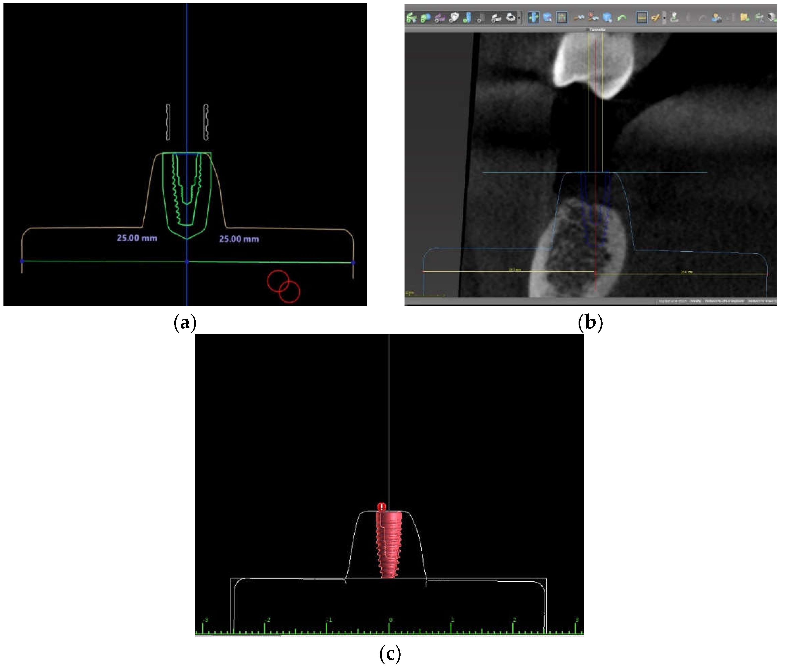
2.2. Implant Position Planning Procedure in Three Different Software Programs

The 90 duplicated models were randomly divided into 3 groups according to the 3 different implant planning software programs. The STL file of each model derived from an extra-oral scanner (D900, three shapes, Copenhagen, Denmark) was transferred into three different implant planning software programs; namely, Implant Studio (3Shape®, Copenhagen, Denmark), coDiagnostiX® (Straumann®, Basal, Switzerland), and Blue Sky Plan (Blue Sky Bio®, LLC, Libertyville, IL, USA). For the remainder of this report, the alphabet is used to represent these implant planning software programs: Program A for Implant Studio, Program B for coDiagnostiX®, and Program C for Blue Sky Plan. In each program, a virtual implant with a diameter of 4.1 mm and length of 10.0 mm of a bone level taper (BLT) Straumann implant system was selected from the existing library. For the determination of the planned implant position, the center axis line of the virtual implant was positioned on the same line of the center axis line of the cylinder-shaped box. Therefore, two-dimensional cross-sectioned images of each study model at 0 degrees (0°) or the mesio-distal aspect and 90 degrees (90°) or the buccolingual aspect adjusted and confirmed the virtual implant axis line and the center axis line of the cylinder-shaped box of the base of the study model that was placed on the same line. With assistance from each implant planning program, a “Ruler tool” or “Measure tool” was used to confirm the virtual implant position and the two-dimensional images at 0 degrees; they also ensured that the distance of the mesial side and the distal side of the virtual implant had equal values (Figure 2). At 90 degrees, the distance of the buccal side and the lingual side of the virtual implant should also have had equal values (Figure 3).

2.3. Surgical Guide Design and Fabrication in Three Different Software Programs

After the implant position planning procedure, a surgical guide was designed in each software program. First, a 2.5 mm thickness three-tooth-supported guide with a 5 mm inner diametric Straumann T-sleeve was selected. The sleeve position was 2 mm (H2) above the bone level. The surgical guide was then designed with two inspection windows at the buccal cusp of the first mandibular premolar and the mesio-buccal cusp of the second mandibular molar. After that, the STL file of the surgical guide was exported to fabricate a surgical guide template with Dental SG Resin material using a 3D printer (Form 2 SLA 3D printer, Formlabs, MA, USA) printed at a 50 µm layer thickness. After the post-curing and post-processing of the surgical template printing for 2 h, a 5 mm inner diametric Straumann T-sleeve was fixed to the surgical template (Figure 4).

2.4. Osteotomy and Implant Placement in the Study Model Process

Before the implant placement procedure, each of the surgical guide templates designed by the three different software programs was placed on its study model and checked for stability via the observation window. The tip of the explorer was not allowed to penetrate through each inspecting window. Each surgical guide was required to be stable and not move on the model. Ill-fitting surgical guides that did not completely sit passively were discarded and replaced.
Once the stability was confirmed by an exploration around the inspection windows, implant bed preparation for each model was performed according to the drilling guidance protocol of the Straumann BLT-guided surgery system via a guided BLT surgical kit (Straumann, institute Straumann AG, Basel, Switzerland). The first drilling used a 2.2 mm diameter medium Pilot BLT Drill with the corresponding drill handle (blue color-coded with a + 3 mm high cylinder) to pre-drill the implant bed. In the second drilling, the implant bed was widened to 2.8 mm diameter via a 2.8 mm diameter medium Guided BLT Drill with the corresponding drill handle (yellow color-coded with a + 3 mm high cylinder). In the final drilling, the implant bed was widened to 3.5 mm diameter via a 3.5 mm diameter medium Guided BLT Drill with the corresponding drill handle (red color-coded with a + 3 mm high cylinder). After that, 1 replica 4.1 × 10 mm Straumann® BLT dummy implant width was placed through the sleeve of the template into each study model at a single edentulous space.

2.5. Implant Position Accuracy Measurement

After the implant placement in each model, the corresponding scan body (CARES® RC Mono Scan Body, Straumann, Basel, Switzerland) was attached and tightened onto each implant using a screwdriver. The adaptability of the implant platform and the scan body was examined. An extra-oral scanner (D900, three shapes, Copenhagen, Denmark) was used to capture each model with the scan body. An STL file of all models with a scan body was then imported into coDiagnostiX® software version 9.7. In the program, the actual implant position was generated from the position of the scan body and superimposed onto the same original planned implant position. The deviation between the planned and placed implants was automatically linearly and angularly evaluated in the “Treatment-Evaluation tool” in the coDiagnostiX® software program. The values of the linear and angular deviations were recorded (Figure 5).
The software automatically calculated the deviation of the placed implant in relation to the planned implant. The outcomes were recorded as follows (Figure 6):
  • Linear deviation from the implant platform: the linear displacement in mm between the planned and placed implants, measured at the center of the implant platform.
  • Linear deviation from the implant apex: the linear displacement in mm between the planned and placed implants as measured at the center of the implant apex.
  • Linear deviation of the implant depth: the depth deviation in mm between the planned and placed implants.
  • Deviation of the implant axis or an angular deviation: the deviation in degrees (°) between the center axis line of the planned and placed implants.
All measuring points were measured at the center of the implant. If the placed implant was shallower than the planned implant, the data were recorded as a negative value. If the implant was placed deeper than the planned implant, the data were recorded as a positive value.

2.6. Statistical Analysis

All measurement data were analyzed by IBM SPSS Statistics software version 18 (SPSS Inc., Chicago, IL, USA). The Shapiro–Wilk was used to test the normal distribution of the data. The data were presented as a mean standard deviation (SD) for the continuous data and a number with a percentage for the categorical data. A one-way ANOVA was used to analyze the differences between the deviations among the three groups and two independent sample t-tests were used to compare the two groups. A chi-squared test or Fisher’s exact test was used to compare the categorical data. The statistical significance was defined as p < 0.05 (Figure 7).

3. Results

3.1. The Deviation of the Placed Implant Related to the Planned Implant

The mean, SD, and p-value of the 3D deviation of the implant platform, implant apex, angulation, and depth between the planned and placed implant position are displayed in Table 1. For the 3D position of the implant platform and the 3D positions of the implant apex and depth, the mean deviations were not statistically significant or different among the three groups. Considering the angular deviation, there was a statistically significant difference between the three groups (p = 0.02). In addition, the mean angular deviation of Program C was significantly greater than the Program A group (p = 0.001).

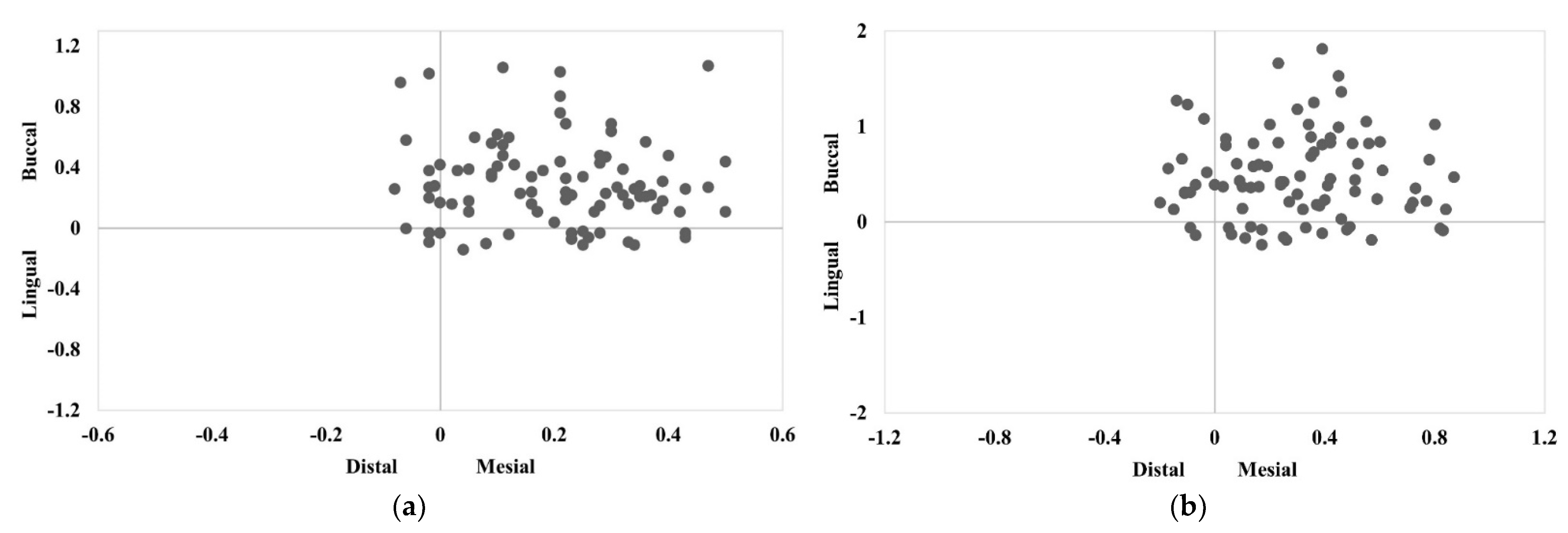
3.2. The Direction of the Buccolingual and Mesio-Distal Deviations of the Implant Position at the Implant Platform and Apex

At the implant platform and apex, the buccal deviation was greater than the lingual deviation; the mesial deviation was greater than the distal deviation for all three groups (Table 2). Figure 8 displays the distribution of the implant platform and apex deviations in the buccolingual and mesio-distal directions. For the three groups, most of the deviations of a larger magnitude were toward the mesio-buccal direction.

4. Discussions

Nowadays, with the development of digital technology for dental implant treatments, implant treatment planning is more precise, reliable, and efficient. The optimal position of implant fixtures can be corrected with assisted devices to improve the accuracy of the implant placement by using a computer-assisted implant system. Several articles have reported that using computer-assisted implant surgery for an implant placement was more accurate than using conventional techniques [6,7,8,9,10]. Currently, there are many software programs used for planning implant positions and designing surgical guides. However, few studies have been undertaken to compare the accuracy of each program. Therefore, in this in vitro study, we aimed to compare the accuracy of these implant planning software programs. We investigated three-dimensional implant positions by using the static surgical guides designed by three different, and widely used, software programs. These were named Program A, Program B, and Program C.
The outcomes of this study were as follows. The implant position planning and the static surgical guide fabrication using all three different implant planning software programs provided three-dimensional implant position deviations at the implant platform, implant apex, and depth. These ranged from 0.38–0.71 mm, 0.44–1.04 mm, and 0.09–0.44 mm, respectively. There were no significant differences between the three-dimensional implant platform, implant apex, and depth deviations between all three groups.
However, an important finding to note from this study was there was a significant difference between the three groups in the angular deviation of the implant placement using the static surgical guides designed by all three implant planning software programs; the mean angular deviations of Program A, Program B, and Program C were 1.72 ± 0.88 degrees, 2.05 ± 1.24 degrees, and 2.74 ± 1.81 degrees, respectively. The mean angular deviation of the Program C group was greater than the Program A and Program B groups. Although the angular deviations between Program C and Program A were statistically significant, these results may not be clinically significant. According to a previous systematic review [11], the accepted clinical research indicated that the mean angular deviation ranged from 1.49 degrees to 8.54 degrees. The angular deviation of the implant axis may be caused by an impression distortion due to a greater strain of the impression material, probably because of the higher forces required for the impression removal [12]. According to the concept of a prosthetic-driven implant treatment, the proper implant position should conform to a definitive prosthesis or restorative position in order to reduce the non-axial occlusal loading force for gaining a proper loading force distribution to the implant and surrounding bone [13]. If the occlusal loading force on the restoration does not distribute to the same vector of the implant axis, a greater and more destructive stress distribution occurs between the implant fixture-supporting bone and the implant fixture abutment. This then causes marginal bone loss and the fracture of the implant abutment connection [14,15]. The angulation of implants is one of the most important factors that influences the distribution of the occlusal loading force to the peri-implant-supported bone. To correct a deviation in the implant angulation to provide a path for a fixed prosthesis insertion, angulated abutments were used [16]. The use of angulated abutments could make the cantilever of the restoration or prosthesis affecting the biomechanics response more fragile due to the increase in stress concentrations on the implants and peri-implant-supported bone [17].
The vertical or depth deviations of the placed implant positions using the surgical guides designed by the three software programs ranged from 0.09–0.44 mm. From this study, most implant positions achieved were more coronal (shallower) than the planned positions. Having a shallower implant position affects the zenith and gingival margin of the final restoration, resulting in a shorter clinical crown appearance when compared with a natural adjacent tooth. For a screw-retained implant, the placement of an implant too coronally may lead to a ridge-lap prosthetic design. This could be corrected by planning a deeper implant position or a deep implant bed preparation. After implant placements, clinicians should also verify that the depth of the implant was at the expecting level. An error in the vertical direction is to be expected (a too superficial implant position). This may be due to the presence of debris in the implant cavity and/or a blockage of the implant holders in the sleeves of the guide during surgery [18,19].
When analyzing the buccolingual and mesio-distal deviation directions of the implant position for all three groups, we observed that most deviations were in buccal and mesial directions. Buccolingual deviations were more numerous than mesio-distal deviations when using the three different implant planning software programs. This was due to surgical guide deformations or bending during the implant bed preparation and the insertion process. Previous studies showed similar results to this study, with the buccolingual direction having a more prominent deviation as it did not have as rigid a structure (e.g., teeth) as the mesio-distal direction [20,21,22]. The accuracy of the implant positioning is important, especially in cases where the implants are placed by computer-guided flapless implant surgery and computer-guided immediate implant placements. Other studies have shown that placing implants too buccally could result in a buccal mucosa recession due to buccal bone resorption. This means that the harmonious gingival course would be significantly disturbed, causing severe esthetic complications. These complications have been frequently observed in immediate implant placement cases [23,24,25]. Buser et al. demonstrated that the presence of a fully intact facial bone wall with a thickness > 1 mm and a thick gingival biotype were the most vital features required for an immediate implant placement [26]. Both of these requirements were taken into consideration for the present study. The present case showed that digital planning software was more advantageous in planning an accurate immediate implant placement in the esthetic zone [27]. Therefore, in cases where static computer-assisted implant placements are used, one must take into account the distance caused by the deviation of the static computer-assisted implant placement, no matter which program is used. Moreover, for immediate implant placement cases where immediate loading is needed, deviations from the implant position may also cause temporary prostheses (prepared beforehand) to not fit properly and to need another clinical adjustment. In a worst case scenario, they may not fit at all and a new impression of the position of the implant fixture would be required to fabricate a new temporary prosthesis.
Many former educational studies often assessed the accuracy of computer-assisted implant surgery by comparing the planned implant position with the actual implant position. Such a comparison technique made by using these methods still results in errors from those digital workflow processes. Many factors have been reported to influence the deviation of implant positions achieved from static computer-assisted implantation systems. These factors include the study design, the quality of the CBCT image and surface scanning data, the file conversion and adaptability of the radiographic data and surface scanning data, the software program, the surgical guide design and fabrication, structures that support the surgical template (mucosa/tooth/bone) or adaptability of the surgical guide on the surgical site, the surgical technique (open flap/flapless), the tolerance between mechanical components related to the fit of the cylindrical sleeve on the surgical guide, implant characteristics, and the experience of the operator [28,29,30,31].
Therefore, in this study, we used various techniques to minimize the overall effect of the confounding factors as much as possible. The same guide design, drill protocol, surgeon, and type of surgical models were used to minimize the confounding factors. To reduce the drilling memorization of the surgeon, different printed guides were used at random for the implant placement. This study was conducted as an in vitro study because in vitro studies allow for more accurate measurements than clinical studies as they provide a better visual field and access for controlling the axis of the drilling instruments and a lack of patient movement as well as the absence of saliva, blood, and soft tissues [32].
According to a prior study, the accuracy of static surgical guides was affected by the stability of the surgical guide during the implant bed preparation and implant insertion processes. According to Giacomo et al., the greatest deviation was found when the stability of the surgical guide could not be achieved [30]. In a study conducted by Pozzi, tooth-supported guides with a single-tooth edentulous space represented the most accurate result [33]. Another study evaluated whether the type and number of teeth supporting the surgical guide could affect the deviation of the static surgical guide or not. It was shown that the accuracy of the surgical guides supported by three posterior teeth was not different to that of full-arch-supported guides [34]. Thus, a single-tooth edentulous space model with a three posterior teeth-supported guide design was used in this study.
Regarding the printing technique, a surgical guide manufactured by the additive technique “3D printing” and the subtractive technique “milling” showed no statistically significant difference between them. Even so, whilst producing comparable accuracy for implant-guided surgery, a surgical guide fabricated by 3D printers could be a substitution. This is due to their ease of production and the diminution of laboratory time and materials; this also increases the cost-effectiveness [35]. Therefore, a printed surgical guide was used for this study.
Implant characteristics are an important factor influencing the accuracy. In this study, bone level taper (BLT) implants were used because past studies have shown that implant design characteristics affected the deviation of the implant position. This was because the different geometry of osteotomy prepared for the different implant macro-designs affected the deviation in the implant position. There are three different main types of implant characteristics (implant macro-designs): soft tissue level (TL), bone level (BL), and bone level taper (BLT). The insertion geometry of BLT implants was tapered whereas the osteotomy of TL and BL was parallel. As a result, the three-dimensional deviation values of the TL and BL implant positions were significantly less accurate than the BLT implants [36].
For the implant insertion step, the guided implant insertion technique was used in this study due to the results of previous studies that reported that a guided implant placement represented a significantly better accuracy than a freehand placement [11,37].
In terms of the experience of the operator, an in vitro study conducted by Rungcharassaeng et al. [27] found no significant differences in the angular and linear deviations at the entry and apical points between the experienced and inexperienced operator groups. However, the depth deviation value of the implant placed by the inexperienced operators had a greater number of errors than the implants placed by the experienced operators. In addition, almost all implants were placed more coronally than the planned position because the depth of the osteotomy and implant was controlled by the contact between the flange of the drill/implant mount and the sleeve of the surgical template. Thus, the inexperienced operators were more careful about the depth of the implant than the experienced group.

5. Conclusions

Within the limitations of this experimental study, it was found that there were no significant differences between the three-dimensional positions at the implant platform, the three-dimensional positions at the implant apex, and the depth deviation between all three groups. It was also found that there was a significant difference in the angular deviation between the three groups. Program A presented the least deviation in all parameters whereas Program C presented the most deviations; however, there was no significant difference between them. Even so, it must be noted that a deviation in all parameters between the placed implant position and the planned implant position still occurred in all three implant planning software programs.

Author Contributions

Conceptualization, B.P. and S.V.; methodology, B.P. and S.V.; software, B.P. and S.V.; validation, B.P. and S.V.; formal analysis, B.P. and S.V.; investigation, B.P. and S.V.; resources, B.P. and S.V.; data curation, B.P.; writing—original draft preparation, B.P.; writing—review and editing, B.P. and S.V.; visualization, B.P. and S.V.; supervision, S.V.; project administration, S.V.; funding acquisition, B.P. and S.V. All authors have read and agreed to the published version of the manuscript.

Funding

This research received no external funding.

Institutional Review Board Statement

Not applicable.

Informed Consent Statement

Not applicable.

Data Availability Statement

Not applicable.

Acknowledgments

The authors gratefully acknowledge the staff at the implant center and the research center of Mahidol University for the use of equipment and facilities.

Conflicts of Interest

The authors declare no conflict of interest.

References

  1. Fortin, T.; Loup Coudert, J.; Champleboux, G.; Sautot, P.; Lavallée, S. Computer-assisted dental implant surgery using computed tomography. Comput. Aided Surg. 1995, 1, 53–58. [Google Scholar] [CrossRef]
  2. Katsoulis, J.; Pazera, P.; Mericske-Stern, R. Prosthetically driven, computer-guided implant planning for the edentulous maxilla: A model study. Clin. Implant. Dent. Relat. Res. 2008, 11, 238–245. [Google Scholar] [CrossRef] [PubMed]
  3. Lee, S.; Betensky, R.; Gianneschi, G.; Gallucci, G. Accuracy of digital versus conventional implant impressions. Clin. Oral Implant. Res. 2014, 26, 715–719. [Google Scholar] [CrossRef] [PubMed]
  4. Somogyi-Ganss, E.; Holmes, H.; Jokstad, A. Accuracy of a novel prototype dynamic computer-assisted surgery system. Clin. Oral Implant. Res. 2015, 26, 882–890. [Google Scholar] [CrossRef]
  5. Widmann, G.; Bale, R. Accuracy in computer-aided implant surgery-A review. Int. J. Oral Maxillofac. Implant. 2006, 21, 305–313. [Google Scholar]
  6. Block, M.; Emery, R.; Lank, K.; Ryan, J. Implant placement accuracy using dynamic navigation. Int. J. Oral Maxillofac. Implant. 2016, 32, 92–99. [Google Scholar] [CrossRef]
  7. Brief, J.; Edinger, D.; Hassfeld, S.; Eggers, G. Accuracy of image-guided implantology. Clin. Oral Implant. Res. 2005, 16, 495–501. [Google Scholar] [CrossRef]
  8. Buser, D.; Janner, S.; Wittneben, J.; Brägger, U.; Ramseier, C.; Salvi, G. 10-year survival and success rates of 511 titanium implants with a sandblasted and acid-etched surface: A retrospective study in 303 partially edentulous patients. Clin. Implant. Dent. Relat. Res. 2012, 14, 839–851. [Google Scholar] [CrossRef]
  9. Buser, D.; Martin, W.; Belser, U.C. Optimizing esthetics for implant restorations in the anterior maxilla: Anatomic and surgical considerations. Int. J. Oral Maxillofac. Implant. 2004, 19, 43–61. [Google Scholar]
  10. Garber, D.A. The esthetic dental implant: Letting restoration be the guide. J. Am. Dent. Assoc. 1995, 126, 319–325. [Google Scholar] [CrossRef]
  11. Tahmaseb, A.; Wismeijer, D.; Coucke, W.; Derksen, W. Computer technology applications in surgical implant dentistry: A systematic review. Int. J. Oral Maxillofac. Implant. 2014, 29 (Suppl. 2014), 25–42. [Google Scholar] [CrossRef] [PubMed] [Green Version]
  12. Sorrentino, R.; Gherlone, E.F.; Calesini, G.; Zarone, F. Effect of implant angulation, connection length, and impression material on the dimensional accuracy of implant impressions: An in vitro comparative study. Clin. Implant. Dent. Relat. Res. 2010, 12 (Suppl. S1), e63–e76. [Google Scholar] [CrossRef] [PubMed]
  13. Canay, S.; Hersek, N.; Akpinar, I.; Aşik, Z. Comparison of stress distribution around vertical and angled implants with finite-element analysis. Quintessence Int. 1996, 27, 591–598. [Google Scholar] [PubMed]
  14. Lin, C.L.; Wang, J.C.; Ramp, L.C.; Liu, P.R. Biomechanical response of implant systems placed in the maxillary posterior region under various conditions of angulation, bone density, and loading. Int. J. Oral. Maxillofac. Implant. 2008, 23, 57–64. [Google Scholar]
  15. Saab, X.E.; Griggs, J.A.; Powers, J.M.; Engelmeier, R.L. Effect of abutment angulation on the strain on the bone around an implant in the anterior maxilla: A finite element study. J. Prosthet. Dent. 2007, 97, 85–92. [Google Scholar] [CrossRef]
  16. Rodrigues, V.; Tribst, J.; Santis, L.; Lima, D.; Nishioka, R. Influence of angulation and vertical misfit in the evaluation of micro-deformations around implants. Braz. Dent. Sci. 2017, 20, 32. [Google Scholar] [CrossRef]
  17. Rodrigues, V.; Tribst, J.; Santis, L.; Borges, A.; Nishioka, R. Biomechanical effect of inclined implants in fixed prosthesis: Strain and stress analysis. Rev. Odontol. UNESP 2018, 47, 237–243. [Google Scholar] [CrossRef]
  18. Tahmaseb, A.; Weijden, J.; Mercelis, P.; De Clerck, R.; Wismeijer, D. Parameters of passive fit using a new technique to mill implant-supported superstructures: An in vitro study of a novel three-dimensional force measurement-misfit method. Int. J. Oral Maxillofac. Implant. 2010, 25, 247–257. [Google Scholar]
  19. Vercruyssen, M.; Laleman, I.; Jacobs, R.; Quirynen, M. Computer-supported implant planning and guided surgery: A narrative review. Clin. Oral Implant. Res. 2015, 26, 69–76. [Google Scholar] [CrossRef]
  20. Bencharit, S.; Staffen, A.; Yeung, M.; Whitley, D., III; Laskin, D.M.; Deeb, G.R. In vivo tooth-supported implant surgical guides fabricated with desktop stereolithographic printers: Fully guided surgery is more accurate than partially guided surgery. J. Oral Maxillofac. Surg. 2018, 76, 1431–1439. [Google Scholar] [CrossRef]
  21. Deeb, G.R.; Allen, R.K.; Hall, V.P.; Whitley, D., III; Laskin, D.M.; Bencharit, S. How accurate are implant surgical guides produced with desktop stereolithographic 3-dimentional printers? J. Oral Maxillofac. Surg. 2017, 75, 2559.e1–2559.e8. [Google Scholar] [CrossRef] [PubMed]
  22. Hinckfuss, S.; Conrad, H.J.; Lin, L.; Lunos, S.; Seong, W.J. Effect of surgical guide design and surgeon’s experience on the accuracy of implant placement. J. Oral Implantol. 2012, 38, 311–323. [Google Scholar] [CrossRef] [PubMed] [Green Version]
  23. Chen, S.T.; Darby, I.B.; Reynolds, E.C.; Clement, J.G. Immediate implant placement postextraction without flap elevation. J. Periodontol. 2009, 80, 163–172. [Google Scholar] [CrossRef] [PubMed]
  24. Evans, C.D.; Chen, S.T. Esthetic outcomes of immediate implant placements. Clin. Oral Implant. Res. 2008, 19, 73–80. [Google Scholar] [CrossRef]
  25. Kan, J.Y.; Rungcharassaeng, K.; Sclar, A.; Lozada, J.L. Effects of the facial osseous defect morphology on gingival dynamics after immediate tooth replacement and guided bone regeneration: 1-year results. J. Oral Maxillofac. Surg. 2007, 65, 13–19. [Google Scholar] [CrossRef]
  26. Buser, D.; Chappuis, V.; Belser, U.C.; Chen, S. Implant placement post extraction in esthetic single tooth sites: When immediate, when early, when late? Periodontology 2017, 73, 84–102. [Google Scholar] [CrossRef]
  27. Rungcharassaeng, K.; Caruso, J.M.; Kan, J.Y.K.; Schutyser, F.; Boumans, T. Accuracy of computer-guided surgery: A comparison of operator experience. J. Prosthet. Dent. 2015, 114, 407–413. [Google Scholar] [CrossRef] [Green Version]
  28. Al Yafi, F.; Camenisch, B.; Al-Sabbagh, M. Is digital guided implant surgery accurate and reliable? Dent. Clin. N. Am. 2019, 63, 381–397. [Google Scholar] [CrossRef]
  29. Behneke, A.; Burwinkel, M.; Behneke, N. Factors influencing transfer accuracy of cone beam CT-derived template-based implant placement. Clin. Oral Implant. Res. 2011, 23, 416–423. [Google Scholar] [CrossRef]
  30. Di Giacomo, G.A.; Cury, P.R.; de Araujo, N.S.; Sendyk, W.R.; Sendyk, C.L. Clinical application of stereolithographic surgical guides for implant placement: Preliminary results. J. Periodontol. 2005, 76, 503–507. [Google Scholar] [CrossRef]
  31. Fokas, G.; Vaughn, V.M.; Scarfe, W.C.; Bornstein, M.M. Accuracy of linear measurements on CBCT images related to presurgical implant treatment planning: A systematic review. Clin. Oral Implant. Res. 2018, 29, 393–415. [Google Scholar] [CrossRef] [PubMed]
  32. Bover-Ramos, F.; Viña-Almunia, J.; Cervera-Ballester, J.; Penarrocha, M.; Mira, B. Accuracy of implant placement with computer-guided surgery: A systematic review and meta-analysis comparing cadaver, clinical, and in vitro studies. Int. J. Oral Maxillofac. Implant. 2017, 33, 101–115. [Google Scholar] [CrossRef] [PubMed]
  33. Pozzi, A.; Polizzi, G.; Moy, P. Guided surgery with tooth-supported templates for single missing teeth: A critical review. Eur. J. Oral Implantol. 2016, 9, 135–153. [Google Scholar]
  34. El Kholy, K.; Lazarin, R.; Janner, S.; Faerber, K.; Buser, R.; Buser, D. Influence of surgical-guide support and implant site location on accuracy of static computer assisted implant surgery. Clin. Oral Implant. Res. 2019, 30, 1067–1075. [Google Scholar] [CrossRef]
  35. Henprasert, P.; Dawson, D.; El-Kerdani, T.; Song, X.; Couso-Queiruga, E.; Holloway, J. Comparison of the accuracy of implant position using surgical guides fabricated by additive and subtractive techniques. J. Prosthodont. 2020, 29, 534–541. [Google Scholar] [CrossRef] [Green Version]
  36. El Kholy, K.; Ebenezer, S.; Wittneben, J.-G.; Lazarin, R.; Rousson, D.; Buser, D. Influence of implant macrodesign and insertion connection technology on the accuracy of static computer-assisted implant surgery. Clin. Implant. Dent. Relat. Res. 2019, 21, 1073–1079. [Google Scholar] [CrossRef]
  37. Park, C.; Raigrodski, A.J.; Rosen, J.; Spiekerman, C.; London, R.M. Accuracy of implant placement using precision surgical guides with varying occlusogingival heights: An in vitro study. J. Prosthet. Dent. 2009, 101, 372–381. [Google Scholar] [CrossRef]
Figure 1. Illustration of the drillable polyurethane study model duplicated from the printed model.
Applsci 12 07005 g001
Figure 2. Illustration of two-dimensional images of the virtual implant position at 0 degrees (0°) or mesio-distal aspect in different programs: (a) Program A; (b) Program B; and (c) Program C.
Applsci 12 07005 g002aApplsci 12 07005 g002b
Figure 3. Illustration of two-dimensional images of the virtual implant position at 90 degrees (90°) or buccolingual aspect in different programs: (a) Program A; (b) Program B; and (c) Program C.
Applsci 12 07005 g003
Figure 4. Illustration of the surgical guide with a 5 mm diameter Straumann T-sleeve.
Applsci 12 07005 g004
Figure 5. The 3D measurement of implant deviation in coDiagnostiX® software. Post-operative implant position (blue) merged with pre-operative implant position (red): (a) buccolingual view; (b) mesio-distal view; and (c) 3D view.
Applsci 12 07005 g005
Figure 6. An illustration of the 3D measurements representing the implant deviation between the planned and the placed implant position.
Applsci 12 07005 g006
Figure 7. Boxplots of mean 3D deviations in implant positions: (a) 3D deviation at implant platform; (b) 3D deviation at implant apex; (c) angular deviation; (d) depth deviation. * Different superscript between 2 groups within the same measurement means that the difference is statistically significant (p < 0.05).
Applsci 12 07005 g007
Figure 8. The distribution of the implant deviations in the buccolingual and mesio-distal directions at: (a) the implant platform; and (b) the implant apex.
Applsci 12 07005 g008
Table 1. The mean three-dimensional deviations and standard deviations of the implant platform, implant apex, angulation, and depth between the planned and placed implant position.
DeviationProgram A
(n = 30)
Program B
(n = 30)
Program C
(n = 30)
p-Value
3D deviation at implant platform
Mean ± SD (mm)
Min–max (mm)
0.55 ± 0.25
(0.39–0.71)
0.52 ± 0.31
(0.38–0.57)
0.56 ± 0.22
(0.43–0.62)
0.84
3D deviation at implant apex
Mean ± SD (mm)
Min–max (mm)
0.72 ± 0.37
(0.44–1.04)
0.73 ± 0.40
(0.51–0.99)
0.9 ± 0.46
(0.57–1)
0.19
Angular deviation
Mean ± SD (degrees)
Min–max (degrees)
1.72 ± 0.88
(1.1–2.4)
2.05 ± 1.24
(1.1–2.8)
2.74 ± 1.81
(1.5–3.5)
0.02
Vertical depth deviation
Mean ± SD (mm)
Min–max (mm)
0.19 ± 0.13
(0.09–0.27)
0.31 ± 0.32
(0.11–0.35)
0.31 ± 0.22
(0.13–0.44)
0.11
Table 2. The amount and percentage of implant platform and implant apex deviations in the buccolingual and mesio-distal directions.
DirectionProgram A
(n = 30)
Program B
(n = 30)
Program C
(n = 30)
The direction of implant platform deviation
Buccolingual deviationBuccal26 (86.67%)25 (83.33%)20 (66.67%)
Lingual4 (13.33%)5 (16.67%)10 (33.33%)
Mesio-distal deviationMesial23 (76.67%)23 (76.67%)29 (96.67%)
Distal7 (23.33%)7 (23.33%)1 (3.33%)
The direction of implant apex deviation
Buccolingual deviationBuccal24 (80.00%)25 (83.33%)20 (66.67%)
Lingual6 (20.00%)5 (16.67%)10 (33.33%)
Mesio-distal deviationMesial23 (76.67%)23 (76.67%)29 (96.67%)
Distal7 (23.33%)7 (23.33%)1 (3.33%)
Publisher’s Note: MDPI stays neutral with regard to jurisdictional claims in published maps and institutional affiliations.

