1. Introduction
A rotary vector (RV) reducer is a high-stiffness precision transmission device widely used in industrial robots, machine tools, medical testing equipment, satellite-receiving systems and other fields [
1]. The PRVT has evolved from the beveloid gear RV reducer. The backlash of the beveloid gear can be adjusted by a high-stiffness disc spring. In theory, it can achieve zero-backlash transmission and high-stiffness transmission, which are essential rotary application prospects.
Scholars have been studying the dynamics of gear systems for a long time. Zheng [
2] developed an analytical-FEM framework to integrate the centrifugal field into mesh stiffness and nonlinear dynamics, focusing on centrifugal force in high-speed working conditions. Shi [
3] proposed a dynamics model for hypoid gears, considering mesh stiffness that is dependent on dynamic mesh force. Based on the accurate 3D model of a logarithmic spiral bevel gear, the operation of spiral cone gear engagement was analyzed and simulated by Xiao [
4]. Xie [
5] presented an improved dynamic model to study the moment rigidity and rotation precision of the BPFRS. The proposed model optimizes the theoretical method for calculating the balls–races contact deflection and contact angle, which can more precisely describe the locus of the inner race groove curvature center. Kahraman [
6] considered factors such as manufacturing and installation errors and time-varying meshing stiffness and established a dynamic analysis model of a single-stage planetary gear system with coupled bending and torsion. Parker [
7] considered tooth flank clearance and variable meshing stiffness established by the nonlinear bending–torsion coupling dynamic model of the planetary transmission system by the lumped parameter method and studied the influence of the flank clearance and gravity on the system dynamics. Kim [
8] considered nonlinear factors such as the time-varying pressure angle and time-varying coincidence degree, established a nonlinear bending–torsion coupling dynamic model of the system, and studied the influence of nonlinear factors on the dynamic response of the system. Ben Marrant [
9] used a planetary gearbox test rig to test and compare the simulation results. The model parameters, time-domain dynamic characteristics, and frequency-domain dynamic characteristics were verified to prove the model’s performance feasibility.
In the field of dynamics, the equivalent torsional stiffness model of reducers for robots based on ANSYS is established in [
10,
11,
12], which focused on the time-varying meshing stiffness of the transmission beveloid gear. In addition, a system dynamic model was presented based on the finite element method, and the inherent characteristics of the beveloid gear were studied. Yang [
13], based on the lumped parameter principle and FE analysis method, comprehensively considered the meshing stiffness of the beveloid gear pinwheel, the pin gear’s supporting stiffness, the torsional stiffness of the crankshaft, the bearing stiffness, etc., and the scientific model and rigid–flexible coupling dynamics analysis model. The research analyzes stiffness, mass, the moment of inertia, and the crankshaft’s eccentricity error on the system’s dynamic characteristics. Rui [
14] established the reducer’s system dynamics analysis model based on FE analysis software, studied and analyzed the parameter’s influence on the system’s dynamic meshing force, and carried out experimental verification and analysis. Hsieh [
15] proposed a series transmission scheme based on the transmission model to establish its system dynamics analysis model and study the new series transmission’s dynamic characteristics. Shan [
16] considered gear meshing stiffness, backlash, transmission error, bearing stiffness, and damping, and established a nonlinear system dynamics analysis model of the reducer based on the lumped parameter method study of the influence of parameters on the dynamic characteristics of the system.
The research on the dynamic characteristics of the RV reducer is mainly focused on the beveloid gears. Xi [
17] established a 5-degree-of-freedom nonlinear torsional dynamic model of the RV reducer and verified it by experiments. Yang [
18] considered the meshing stiffness of the beveloid gear, the torsional stiffness of the crankshaft, and the bearing’s stiffness by establishing a dynamic RV model reducer based on the lumped parameter method and analyzed the free vibration characteristics of the system. Zhao [
19] showed a dynamic RV reducer model with 16 degrees of freedom and analyzed the system’s natural frequency and corresponding vibration mode. Li [
20] established the torsional vibration mechanics model of the involute variable tooth thickness and small tooth difference precision reducer using the transfer matrix method and analyzed the system’s dynamic characteristics. Wen [
21] established a bending–torsion-axis coupling dynamics model of the RV reducer system with two crankshafts with variable tooth thickness. Still, each component in the model only considered one radial DOF and did not consider the disc spring. It is not easy to reflect the system’s dynamic characteristics accurately and completely in the three-crank shaft RV reducer for axial vibration analysis of the beveloid gear. The above article did not study the torsional stiffness of the reducer. In engineering applications, the reducer’s torsional stiffness has attracted a lot of attention in the industrial sector, and it has become more and more urgent to study the torsional stiffness of the PRVT.
This paper considers the transmission principle and structural characteristics of the PRVT. Based on the lumped parameter method, the gear teeth time-varying meshing stiffness, bearing stiffness, disc spring stiffness, damping, and transmission error are considered to establish a dynamics model of the whole machine. Furthermore, the influence of machining errors on dynamic torsional stiffness is studied. This paper provides a theoretical basis for analyzing and optimizing the dynamic torsional stiffness of the PRVT.
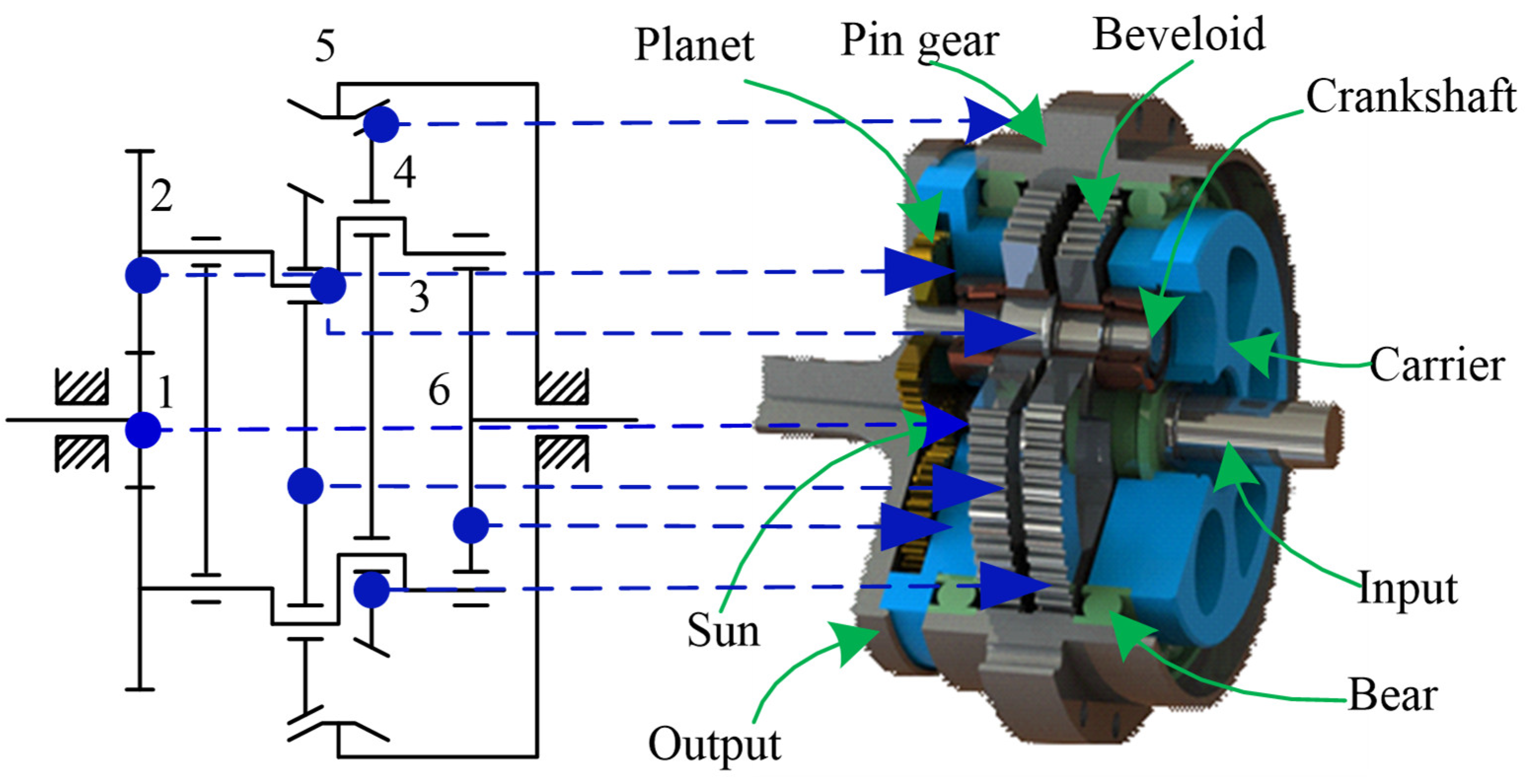
2. Transmission Principle
The transmission principle of the PRVT is shown in
Figure 1. It consists of a one-stage planetary gear transmission and a one-stage variable tooth-thickness gear with small tooth difference transmission. Through gear meshing, the torsional motion is transmitted to gear 2 through pinion 1, further driving crankshaft 3 to rotate; gear 4 is driven by the crankshaft as a plane and meshes with gear 5, and finally outputs a low-speed rotation through support plate 6. The transmission ratio
i can be obtained as:
where
,
,
, and
are the numbers of teeth in the gears of 1, 2, 4, and 5, respectively.
3. Dynamic Modeling
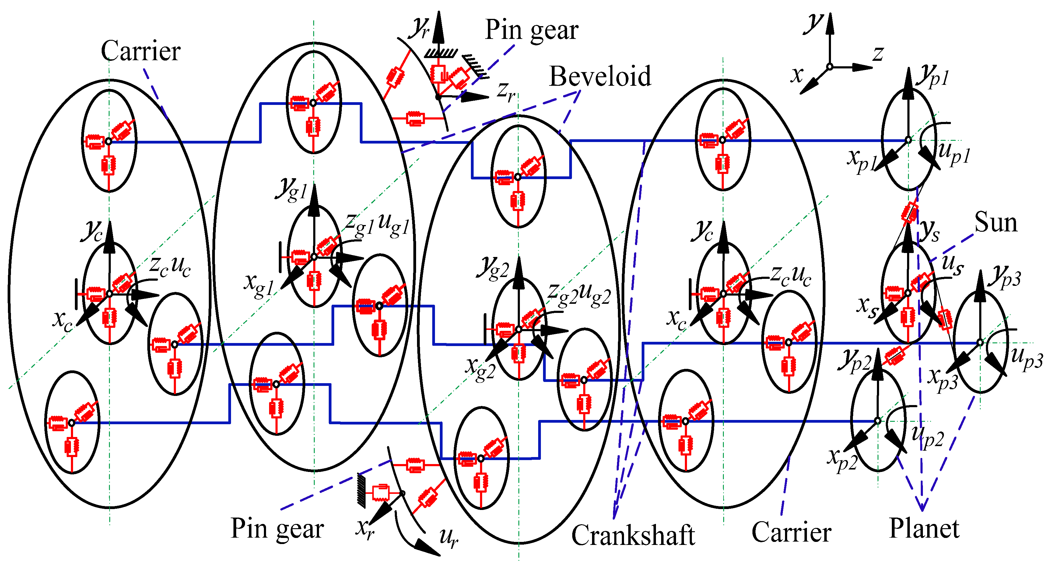
The model considers 11 components: the sun, planet, carrier, crankshaft, pin gear, and beveloid gear in
Figure 2. The coordinate system
is established on the internal gear with variable tooth thickness (fixed during operation) with its geometric center as the origin.
We established a dynamic co-ordinate system on the remaining components with their respective geometric centers as the origins: (i = 1, 2, 3), (j = 1, 2, 3), and (k = 1, 2).
The first-stage planetary transmission has no axial force, so the vibration displacement of the sun along the axis, axis and direction, and the vibration of the planet gear along the axis, axis and direction is considered. The beveloid gear is subjected to radial force, axial force, and torque during meshing, and the beveloid gear and the carrier are adjusted by the elastic deformation of the disc spring axial displacement. Therefore, the vibration displacement (k = 1, 2) of the beveloid gear is considered along the axis, axis, axis and direction (k = 1, 2), where 1 and 2 show carrier and crank, respectively. The shafts are subjected to radial force, axial force, and torque, respectively. Hence, the vibration displacement of the carrier is considered along the axis, axis, axis and direction. Having a look at crankshaft along the axis, axis, it is obvious that the vibration displacements are along the axis and direction (j = 1, 2, 3).
For multi DOF gear dynamic systems, it is more convenient to use Lagrangian equations to establish dynamic models [
22,
23]. The system kinetic energy, potential energy, and dissipation energy of the PRVT are shown in Equations (2)–(4).
System kinetic energy:
where
: the moment of inertia and mass of each component;
: the vibration speed of each component;
;
;
: respectively represent the sun, planet gear, carrier, crankshaft and beveloid gear and pin gear.
System potential energy:
where
: the time-varying meshing stiffness of the sun and planetary gears;
: the tangential meshing stiffness and axial meshing stiffness of the pin gear and beveloid gear;
(i = 1, 2, 3): the bearing between the support plate and the crankshaft, which supports rigidity in the radial and axial directions;
(i = 1, 2, 3): the radial support stiffness of the bearing between the beveloid gear and the crankshaft;
: disc spring stiffness;
(i = s, c): the support bearing of the sun and carrier support rigidity in the radial and axial directions;
: the radial and axial support rigidity of the beveloid gear;
: the relative vibration displacement of the sun and planetary gear along the meshing line;
: the projection of the relative vibration displacement of the beveloid gear and pin gear along the meshing line on the end face and the axial direction;
(i = 1, 2, 3): the radial and axial relative vibration displacement between the carrier and the crankshaft;
(i = 1, 2, 3; j = 1, 2): the relative vibration displacement between the beveloid gear and the crankshaft in the radial direction;
(i = 1, 2): the axial relative vibration displacement between the beveloid gear and the carrier.
System energy dissipation:
where
: the meshing damping of the sun and planetary gears;
: the tangential meshing damping and axial meshing damping of the beveloid gear and pin gear;
(i = 1, 2, 3): the bearing between the support plate and the crankshaft, which supports damping in the radial and axial directions;
(i = 1, 2, 3, j = 1, 2): the bearing of radial support damping between the beveloid gear and the crankshaft;
(i = s, c, sh): the supporting bearing of the sun and carrier support damping in the radial and axial directions;
: the beveloid gear, which supports damping in the radial and axial directions;
: the relative vibration of the sun and planetary gears along the meshing line, the projection of the relative vibration velocity of displacement, and the beveloid gear and pin gear along the meshing line on the end face and the axial direction;
(i = 1, 2, 3): the planetary carrier radial and axial relative vibration velocity between the crankshaft and the crankshaft;
(i = 1, 2, 3; j = 1, 2): the relative vibration speed of the beveloid gear and crankshaft along the radial direction;
(i = 1, 2): the axial relative vibration speed between the beveloid gear and the carrier.
According to the Lagrangian principle,
where
.
Substituting Equations (2)–(4) into Equation (5), the vibration differential equation of the precision reducer system with variable tooth thickness and slight tooth difference can be obtained, as shown in Equation (6).
The system dynamics equation can be sorted into the following matrix form, as shown in Equation (7).
where
: generalized coordinate vector;
: quality matrix;
: support damping and support stiffness matrix of the bearing;
: stiffness matrix of the disc spring;
: support damping and support stiffness matrix of internal gears with variable tooth thickness;
: gear meshing damping and meshing stiffness matrix;
: statically transferred error vector and load vector.
4. Torsional Stiffness Analysis
The dynamic torsional stiffness of the prototype was analyzed using the above dynamics model. The main parameters of the prototype are shown in
Table 1. The bearing stiffness and damping were calculated according to the reference [
23], while the meshing stiffness value of planetary gears was obtained from the same article. The meshing stiffness of the beveloid gear was obtained from [
24] by using FE calculation. The disc spring stiffness is based on literature [
25] by taking
= 4.5 × 10
6 N/m.
The torsional stiffness of the whole machine can be calculated from the output torque, input angle and output angle, as shown in Equation (8).
where
: transmission ration;
: output torque;
: input angle;
: output angle.
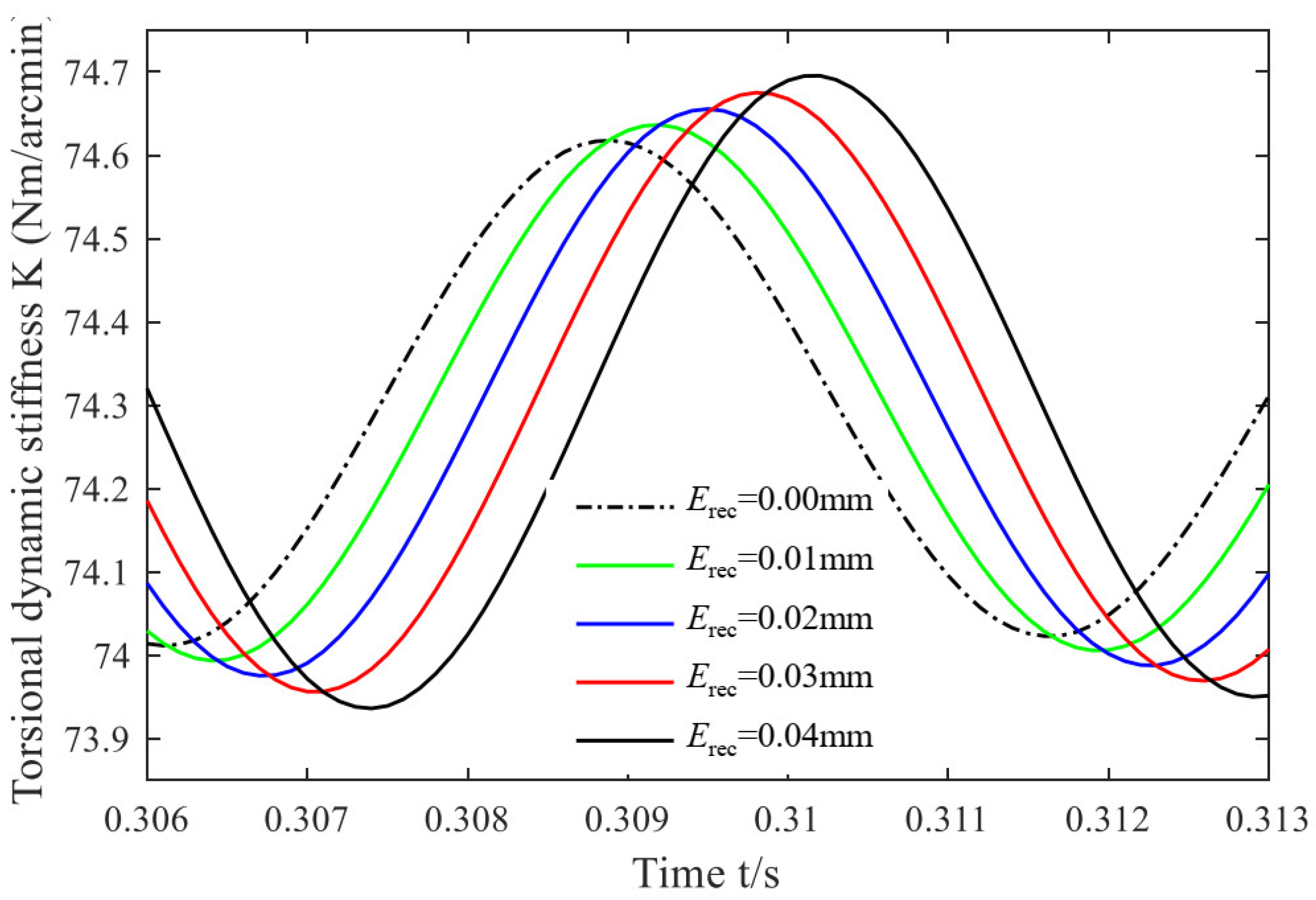
4.1. The Crank Distribution Circle Radius Error of the Crankshaft vs. the Torsional Stiffness
Under other unchanged conditions, the error of the radius of the crank distribution circle of the crankshaft is changed to
= 0.00, 0.01, 0.02, 0.03, 0.04 mm. Through simulation analysis, the corresponding influence curve of the system’s torsional stiffness is obtained in
Figure 3.
Due to damping, the torsional stiffness gradually decays with time and finally stabilizes to near a value. As can be seen from
Figure 3, the dynamic torsional stiffness exhibits an approximately sinusoidal variation with time. The phase difference of different curves does not evidently change (the slope is 1 × 10
−2 s/mm), and the period has changed inconspicuously (the slope is 0 s/mm). The peak-to-peak torsional stiffness of the system under different
is 0.39, 0.40, 0.41, 0.42, and 0.43 Nm/arcmin (the slope is 1000 N/arcmin), while the average values are 74.32, 74.31, 74.33, 74.30, and 74.32 Nm/arcmin (the slope is 0 N/arcmin), respectively. It can be seen from the figure that the peak-to-peak value of torsional stiffness increases with the increase of
. However, its mean value does not change significantly.
4.2. The Distribution Circle Radius Error of the Crankshaft Bearing Hole on the Carrier vs. the Torsional Stiffness
Under other unchanged conditions, the variation in the error of the partial circle radius of the crankshaft bearing hole was investigated for
= 0.00, 0.01, 0.02, 0.03 and 0.04 mm. Through simulation analysis, the corresponding influence curve of the system’s torsional stiffness is obtained in
Figure 4.
It can be seen from
Figure 4 that the dynamic torsional stiffness exhibits approximately sinusoidal fluctuations with time. The phase difference of the different curves increases significantly (the slope is 3 × 10
−2 s/mm), while the period has changed inconspicuously (the slope is 0 s/mm). The peak-to-peak torsional stiffness of the system under different
is 0.57, 0.60, 0.64, 0.68, and 0.71 Nm/arcmin (the slope is 3500 N/arcmin), and the average values are 74.34, 74.35, 74.33, 74.34 and 74.33 Nm/arcmin (the slope is 0 N/arcmin), respectively. It can be seen from the figure that the peak-to-peak value of torsional stiffness increases with the increase of
, but its mean value does not change significantly.
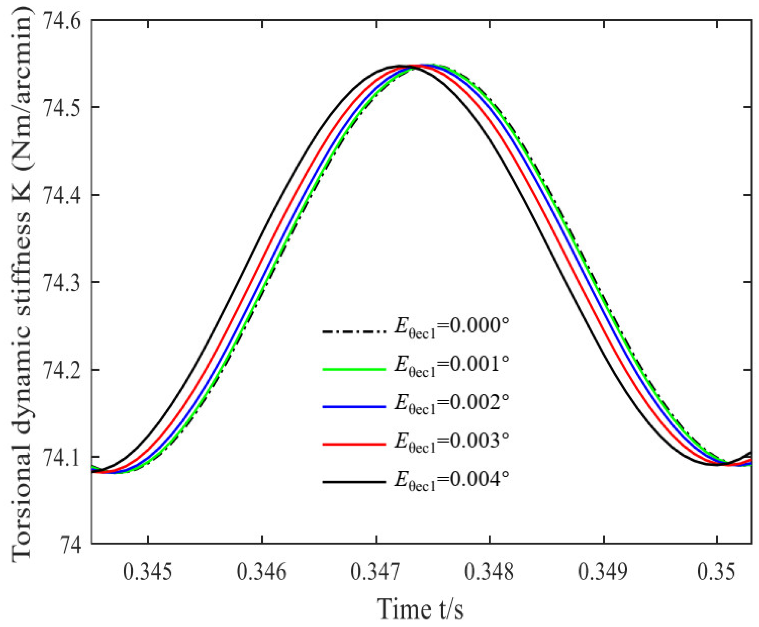
4.3. The Angle Error of the Crankshaft Bearing Hole on the No. 1 Carrier vs. the Torsional Stiffness
Under similar conditions as described in
Section 4.2, here we analyzed the change in the rotation angle error of the crankshaft bearing hole on the No. 1 carrier to
= 0. 000°, 0. 001°, 0. 002°, 0. 003° and 0. 004°. Through simulation analysis, the corresponding influence curve of the system’s torsional stiffness is obtained in
Figure 5.
It can be analyzed from
Figure 5 that the curve of dynamic torsional stiffness with time presents an approximately smooth cosine curve. However, the phase difference of different curves does not evidently change (the slope is 6 × 10
−2 s/°), and the period has not changed obviously (the slope is 0 s/°). The peak-to-peak torsional stiffness of the system under different
are 0.46, 0.47, 0.45, 0.48, and 0.46 Nm/arcmin (the slope is 0 N/arcmin), and the average values are 74.30, 74.32, 74.31, 74.32, and 74.30 Nm/arcmin (the slope is 0 N/arcmin), respectively. It can be seen from the figure that the peak-to-peak value and average value of torsional stiffness have no obvious changes with the increase in
.
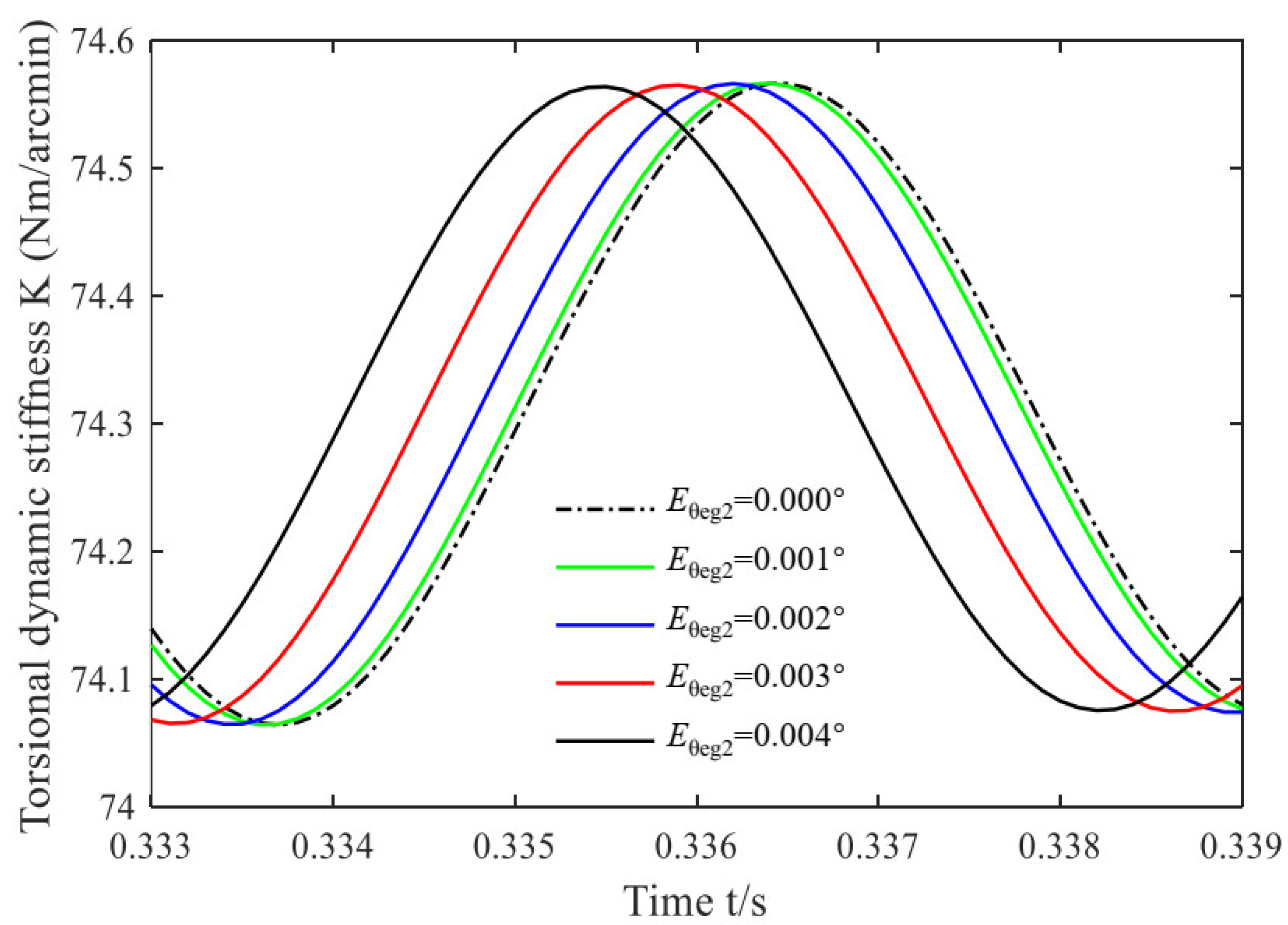
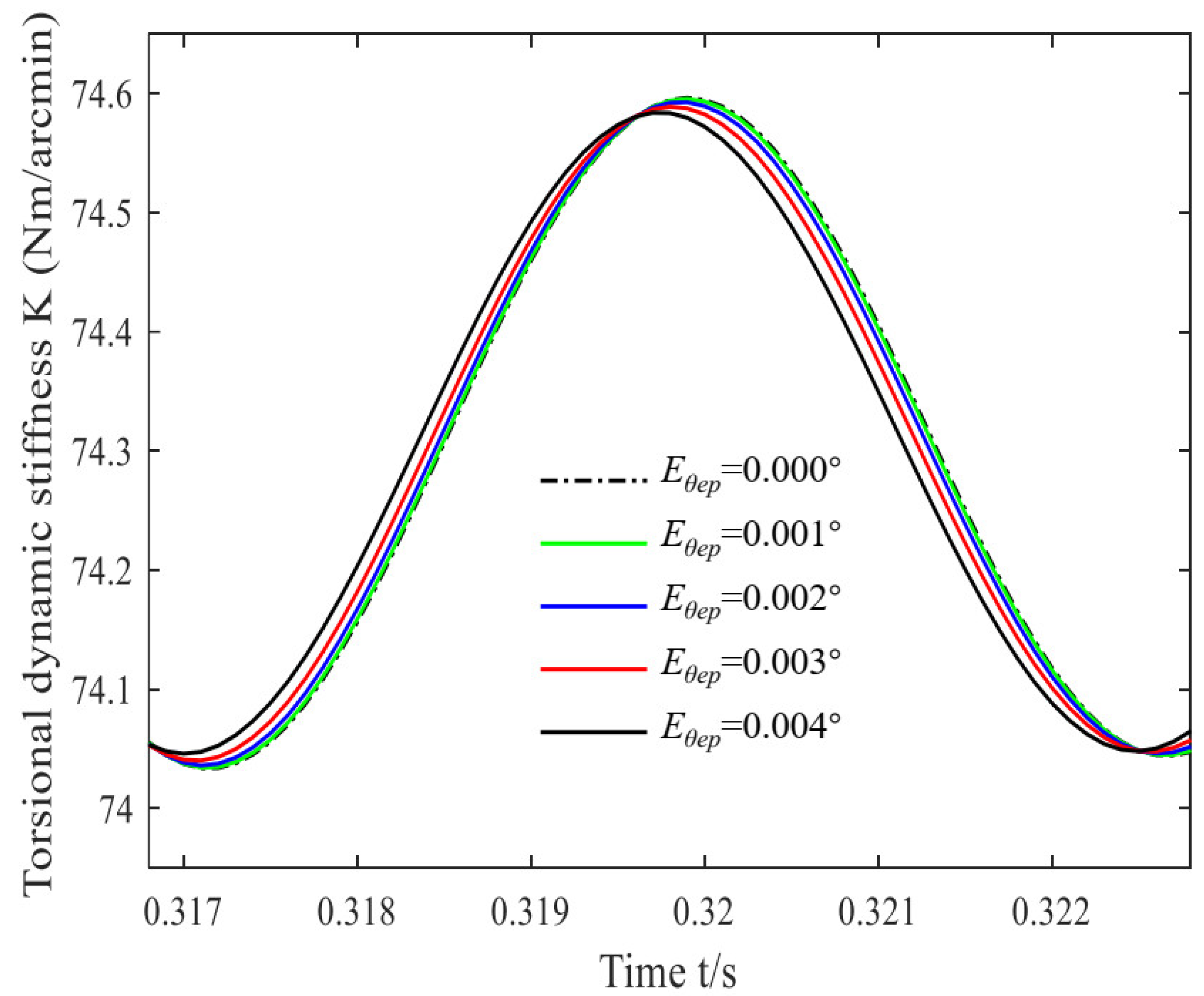
4.4. The Angle Error of the Crankshaft Bearing Hole on the No. 1 Beveloid Gear vs. Torsional Stiffness vs. Torsional Stiffness
Under other unchanged conditions, we changed the angle error to
= 0.000°, 0.001°, 0.002°, 0.003°, and 0.004°. Through simulation analysis, the corresponding influence curve of the system’s torsional stiffness is obtained in
Figure 6.
From
Figure 6, it can be found that the dynamic torsional stiffness exhibits approximately sinusoidal fluctuations with time. The phase difference of the different curves increases relative to
Figure 5 (the slope is 2.5 × 10
−1 s/°); however, the period has not changed obviously (the slope is 0 s/°). The peak-to-peak torsional stiffness of the system under different
are 0.45, 0.46, 0.45, 0.44, 0.45 Nm/arcmin (the slope is 0 N/arcmin), and the average values are 74.30, 74.32, 74.31, 74.32, 74.30 Nm/arcmin (the slope is 0 N/arcmin), respectively. It is obvious from the figure that the peak-to-peak value and average value of torsional stiffness have no obvious change with the increase of
.
4.5. The Crank Angle Error of the Crankshaft vs. the Torsional Stiffness
Following similar conditions as described in previous sections, the impact of change in the crank angle error for the crankshaft was studied by using
= 0.000°, 0.001°, 0.002°, 0.003°, and 0.004°. Through simulation analysis, the corresponding influence curve of the system’s torsional stiffness is obtained in
Figure 7.
It can be analyzed from
Figure 7 that the curve of dynamic torsional stiffness with time presents a smooth sinusoidal curve. However, the phase difference (the slope is 2 × 10
−2 s/°) and period variation of the different curves are relatively small (the slope is 0 s/°). The peak-to-peak torsional stiffness of the system under different
are 0.57, 0.56, 0.55, 0.53, and 0.51 Nm/arcmin (the slope is −3500 N/arcmin), and the average values are 74.30, 74.31, 74.30, 74.32, 74.30 Nm/arcmin (the slope is 0 N/arcmin), respectively. It can be seen from the figure that the peak-to-peak value of torsional stiffness increases with the increase in
, but its mean value does not change significantly.
5. Conclusions
In this study, a dynamics model of the PRVT based on the Lagrangian method was established. The gear meshing stiffness, damping, and the influence of machining errors on dynamic torsional stiffness were considered in this model. Through error impact analysis, the main conclusions are summarized as follows:
(1) By considering parameters such as gear time-varying meshing stiffness, bearing stiffness, disc spring stiffness, damping, and transmission error, a dynamic model of the PRVT coupled with the two-stage transmission is established based on the Lagrangian equation.
(2) Based on the dynamics model, the impact of machining errors on dynamic torsional stiffness was investigated. The results show that the crank distribution circle radius error of the crankshaft (the slope is 1000 N/arcmin) and the distribution circle radius error of the crankshaft bearing hole on the carrier (the slope is 3500 N/arcmin) will cause the peak-to-peak torsional stiffness to increase, and the latter is 3.5 times the former. It can be found that the distribution circle radius error of the crankshaft bearing hole on the carrier has a greater impact on torsional stiffness than the crank distribution circle radius error of the crankshaft. In contrast, the crank angle error of the crankshaft (the slope is −3500 N/arcmin) will cause the peak-to-peak torsional stiffness to decrease. To improve the whole machine’s stability, it is necessary to control the error within a reasonable range.
(3) The rotation angle error of the crankshaft bearing hole on the No. 1 carrier and the crankshaft bearing hole rotation error has no significant effect on the peak-to-peak value of torsional stiffness (the slope is 0 N/arcmin). Therefore, to reduce the whole machine’s processing cost, it is recommended to properly address these machining errors. When the slopes of the torsional stiffness average are 0 N/arcmin, the machining errors researched in the paper have no significant effect on the torsional stiffness.
(4) For different machining errors, the cyclic variation in the curve and its influence on torsional stiffness is small. The impact of the distribution circle radius error of the crankshaft bearing hole on the carrier on dynamic torsional stiffness is 3 times that of the crank distribution circle radius error of the crankshaft. The impact of the rotation angle error of the crankshaft bearing hole on the No. 1 carrier on dynamic torsional stiffness is 4.17 times that of the distribution circle radius error of the crankshaft bearing hole, and 12.5 times that of the crankshaft bearing hole rotation error.
(5) For further research, it is highly recommended to consider the dynamic mesh stiffness and subsurface stress at the same time for gear reducers to further analyze the variational patterns of the torsional stiffness.


