Abstract
The water-lubricated tilting pad thrust bearings (WTTBs) of the reactor coolant main pump and high-power RDT operate at a large linear velocity, heavy load, and low viscosity. On the basis of the performance prediction of WTTBs in the mixing flow pattern, a hypothesis of the regional flow pattern is proposed. To compare the lubrication performance under four kinds of flow pattern modes, a thermo-elasto-hydrodynamic lubrication model of the WTTB considering the flow pattern is established, and a partition iteration algorithm for the mixing flow pattern is provided. Moreover, a method for controlling the flow pattern by changing the pad surface morphology is proposed. A simulation is used to indicate that the bearing performance under the mixing flow pattern calculated by the regional flow pattern mode is between that of the laminar and turbulent flows. The regional mixing flow pattern mode can automatically retrogress to the single flow pattern mode by changing the operation conditions. Both the circumferential bulge and radial concave pad surfaces are beneficial for increasing the turbulent area and thereby improving the load-carrying capacity of the WTTB.
1. Introduction
Water-lubricated thrust bearings (WTBs) are the key support components of reactor coolant main pumps [1] and new marine thrusters [2]. The propeller thrust of a ship’s rim-driven thrusters (RDTs) is borne by the WTBs. As a result of the low viscosity of water, the load-carrying capacity of water-lubricated bearings is weaker than that of oil-lubricated bearings under the same working conditions, leading to lubrication failure and abnormal wear [3]. Moreover, the WTBs of the reactor coolant main pump and high-power RDT (more than 3 MW) operate at a large linear velocity (70~90 m/s), heavy load (≥0.5 MPa), and low viscosity, resulting in a quite different Reynolds number distribution of the pads. In this case, the pad surface is not a single pattern of laminar or turbulent flow but rather a mixed flow pattern. Complex flow characteristics make it difficult to establish the lubrication model and affect the accuracy of bearing performance prediction.
Experiments are important means by which to explore flow patterns and their transformation phenomena. Gardner et al. [4] found that parameters such as the bearing power loss and increase in temperature affect the increase in speed in the bearing test of steam turbine units and speculated that this phenomenon may be related to the transition of the flow pattern. Chu et al. [5] observed the generation and development of laminar flow instability and the Taylor vortex in a sliding bearing through a dyeing test and obtained pictures of the flow pattern transition process. Zhang et al. [6] observed the flow pattern transition process of an oil-lubricated journal bearing using the bubble tracing method and photographed the coexistence of laminar and turbulent flow. These tests provide direct proof of the existence of a mixed flow pattern.
Bearing mixed flow pattern modeling is also a research hotspot, as some scholars have tried to use the three-dimensional N–S equation to explain the relationship of laminar flow to turbulent flow, but the calculation’s accuracy remains to be verified. Improvement of the turbulence model is a feasible method for a mixed flow. The Constantiscu model [7], Ng–Pan model [8], and Elrod–Ng model [9] are the most popular turbulence models presently. Bou Said et al. [10] studied the influence of journal inclination on the static and dynamic characteristics of journal bearings reinforced by low dynamic visibility fluid in laminar and turbulent flow, respectively. Kosasih et al. [11] proposed a new model of Reynolds stresses for transition-turbulent theory and used it to analyze the sector-shaped thrust bearing in the transition region. Bouard et al. [12] studied the effect of turbulence on the thermo-hydrodynamic performance of tilting pad journal bearings and found that the effect of the non-laminar flow on the predicted performance was not negligible at high rotational speeds. Wang et al. [13] established a database of turbulent lubrication parameters. Their simulation results obtained for the bearing performance were closer to the test results than the common turbulence model, but the coexistence of laminar and turbulent flows was not considered. Jean Frêne et al. [14] presented turbulence models for combined Couette–Poiseuille flows, and the effects of the inertia forces on the laminar and turbulent flows were discussed. Shenoy et al. [15] researched the effect of turbulence and misalignment on the steady state characteristics of a centrally loaded single-pad externally adjustable bearing using the Ng–Pan model. Bendaoud et al. [16] investigated the turbulent flow pattern and the elastic effect in a journal bearing subjected to high speeds using ANSYS CFX. Lv et al. [17] thought that turbulence may locally develop in a large bearing and found that turbulence decreased the speed of the transition from a mixed-lubrication regime to a hydrodynamic lubrication regime.
In summary, the theory of full laminar and turbulent flows is relatively mature. However, the mechanism of mixing flows is not clear as no recognized simulation method has been proposed, and the theory of the coexistence and transition of laminar and turbulent flows needs to be improved. Moreover, there have been few reports on the research of an active control method for the sliding bearing flow pattern.
This paper intends to explore the regional characteristics of water-lubricated tilting pad thrust bearings (WTTBs) and optimize the lubrication performance by adjusting the size of the flow pattern region. Section 2 establishes a lubrication model of WTTBs through analyzing the flow patterns and proposes an algorithm for a regional mixing flow pattern. The regional characteristics of the bearing simulation are investigated in Section 3. Section 4 and Section 5 provide a method for controlling the flow pattern by changing the pad surface morphology, and the effectiveness of the method is verified by numerical calculations. Finally, the authors draw their conclusions and outlook in Section 6 and 7.
2. Lubrication Model and Algorithm of the Regional Flow Pattern
The Reynolds number can be defined as in Equation (1), where the choice of a different gap h determines the flow pattern modes: (1) a single flow pattern assumption [7,8,9], where assuming that all parts of the bearing are in the same flow state, h takes a single value, and (2) the node flow mixing pattern assumption, where assuming that the flow patterns of the node are independent, h takes the film thickness value of each node of the bearing interface grid and extracts the Reynolds number at the node of the film distribution as the flow pattern judgment object to establish the mixing flow pattern lubrication model. However, this mode is contrary to the viewpoint that the flow state has macroscopic behavior in fluid mechanics:
where U is the linear velocity and ρ and μ are the density and dynamic viscosity of the lubricant, respectively.
The Reynolds number distribution of the WTTB on the pad’s surface is quite different under a large linear velocity and heavy load. The flow pattern of the lubrication interface may have regional characteristics. As shown in Figure 1, the pad interface is divided into laminar and turbulent flow areas, and the transition boundary of the two regions is taken as a transition line. The laminar and turbulent lubrication models are used for each region, and the bearing performance is obtained after a comprehensive solution.
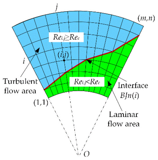
Figure 1.
Partitioning flow pattern of the WTTB.
2.1. Governing Equations
- The Reynolds equation
As shown in Figure 2, the pad surface of the WTTB is fan-shaped, and the pad can be tilted around the fulcrum. R1 and R2 are the inner and outer radii of the pad, respectively. θ0 is the pad sector angle. The Reynolds equation considering the flow pattern and ignoring the inertial force effect according to [18,19] is as follows:
where Gr and Gθ are the flow pattern coefficients. In the laminar flow region, Gr = Gθ = 1/12. In the turbulent region, the coefficients [7] are as follows:
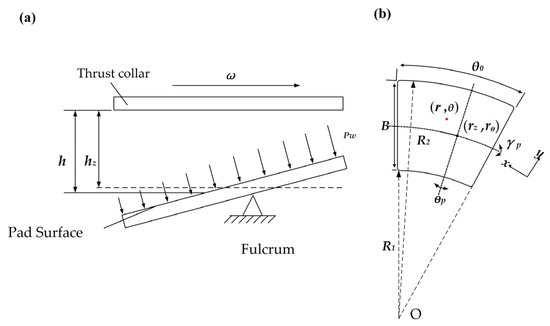
Figure 2.
Structure schematic of the WTTB: (a) tilted state and (b) geometry.
In the turbulent region, h is the average film thickness.
The boundary condition is as follows:
- 2.
- The energy equation
The steady state two-dimensional energy equation considering the flow pattern according to [20] is as follows:
where kτ is the shear turbulence coefficient.
The boundary condition is as follows:
- 3.
- The viscosity–temperature equation
The relationship between the dynamic viscosity and temperature of the water is as follows:
where A, B, and C are constants and equal to 2.16 × 10⁻⁵ Pa·s, 619.29 K, and 141.69 K, respectively.
- 4.
- The film thickness equation
The film thickness equation of the WTTB considering the pad deformation is as follows:
where hz is the film thickness at the fulcrum of the pad, γp is the swing angle of the pad, θp is the position angle of the pitch line, rz and θz are the radial and circumferential positions of the fulcrum, respectively, and δ(r,θ) is the deformation of the pad.
- 5.
- The elastic deformation equation
The Young’s modulus of the pad surface is small, and Boussinesq’s deformation model does not fit it well [21]. The elastic deformation equation of the pad surface can be defined as
where G(r,θ,i,j) is the pad surface’s deformation coefficient produced by the water film pressure acting at the node, Ω is the water film area, and δ(r,θ) is the deformation of the node (i,j). In the three-dimensional model of the bearing, G(r,θ,i,j) can be calculated using the Finite Element Method (FEM) when the element center node (i,j) is subjected to a unit of pressure. When the product of G(r,θ,i,j) and p(i,j) is integrated in Ω, the deformation of the pad surface can be obtained.
- 6.
- Water flow
The water flow drawn into each pad film at the leading edge is calculated as follows:
- 7.
- Power loss
The power loss of each pad is calculated as follows:
- 8.
- Load-carrying capacity
The dimensionless form of each pad’s load-carrying capacity is calculated as follows:
where P is the specific pressure, S is the superficial area of the pad, hmin is the minimum film thickness, and B is the width of the pad.
2.2. Algorithm
As shown in Figure 3, a multiple iterative numerical algorithm for the partitioning flow pattern is used to solve the model. We input the initial film thickness and tilt parameters of the pad and calculated the deformation coefficient G(r,θ,i,j) using the FEM. The Reynolds equation and the energy equation were solved using the Finite Difference Method (FDM) [22]. In order to accelerate the convergence, the over-relaxation iteration method was used. The calculation process included the iteration of the pressure field and temperature field. In addition, the minimum film thickness was corrected in the load-carrying capacity iteration. In the iteration of the pad balance position, the tilt parameter of the pad was modified.
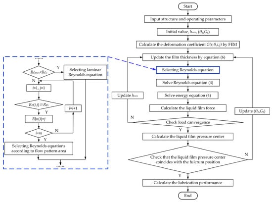
Figure 3.
Flow chart of partitioning flow pattern.
The core of the arithmetic lies in the partitioning of regions and the choice of Reynolds equations. The basic procedures of the algorithm are as follows: (1) divide the pad into m × n grids, where the vertices of each grid represent nodes, (2) compare the nodes’ Reynolds numbers Re(i,j) with the critical Reynolds number Rec to find out the nodes that are approximately equal to each other, defining them as BJn(i), and (3) connect all BJn(i) into a line as the junction line between the laminar and turbulent flow areas.
Rec can be used to define the transition from laminar to turbulent flow as the fluid flow rate increases. It can be found in [23] that Rec equals 1600. Remax is the maximum node Reynolds number. For the turbulent flow pattern (single flow pattern), the average Reynolds number can be calculated using the average film thickness, average viscosity, and average linear velocity. The flow coefficients can be obtained by inputting the average Reynolds number into Equation (3). The bearing performance is obtained by solving the turbulence model. For the node mixing flow pattern, Re(i,j) is compared with Rec. If it is less than Rec, the flow coefficient of the node is taken to be 1/12. Otherwise, the flow coefficient can be calculated through Equation (3). The distribution of the flow pattern coefficient is substituted into the Reynolds equation and energy equation. The bearing lubrication performance is obtained by solving the node lubrication model. For the regional mixing flow pattern, it combines the features of the two above patterns. The pad interface is divided into a laminar and turbulent flow area by comparing Re(i,j) with Rec. The laminar and turbulent lubrication models are used for each region, and the bearing performance is obtained after a comprehensive solution.
3. Simulation of the Regional Characteristics of a Bearing Flow Pattern
The pad surface of the WTTB is made of a polymer composite material. The input parameters are listed in Table 1.

Table 1.
The initial parameters.
3.1. Performance Comparison of Bearings under Different Flow Patterns
When the rotational speed was 300 r/min and the specific pressure was 0.5 MPa, the minimum and maximum Reynolds numbers were 910 and 2660, respectively. The bearing performance obtained under the four flow patterns is shown in Table 2. It can be seen that the bearing performance values varied greatly under different flow modes. Although there was no obvious difference in the maximum film pressure and maximum temperature under the four flow patterns, the minimum film thickness difference between the laminar and turbulent flow patterns was about 6 μm. Therefore, it is very important to explore the flow pattern for the design of a WTTB with a small film thickness.
Table 2.
The lubrication performance obtained under four kinds of flow state modes (300 r/min, 0.5 MPa).
Twenty grids were divided equally along the circumferential and radial directions of the pad, and the flow pattern partition of the pad interface was obtained using the regional mixing flow pattern mode. As shown in Figure 4, the blue and green areas are turbulent and laminar flow areas, respectively. The red line is the boundary between the two areas. The bearing should be in a mixing flow state, and the area ratio of the laminar flow area to the turbulent flow area was about 0.87:1.
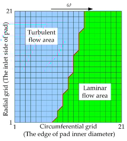
Figure 4.
Zone map of the mixing flow pattern (300 r/min, 0.5 MPa).
3.2. Transition Characteristics of the Flow Pattern Region
The rotational speeds and loads determine the film thickness distribution of the bearing, which in turn affects the Reynolds number of the pad. Figure 4 presents the simulation results obtained for the bearing performance under the four flow patterns at different rotational speeds. As shown in Figure 5a–c, when the rotational speed was less than 260 r/min, the minimum film thickness, power consumption, and inlet flow rate of the regional mixing flow pattern were close to those of the laminar flow pattern. When the rotational speed was greater than 360 r/min, the values almost coincided with those of the turbulent flow pattern.
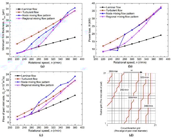
Figure 5.
The lubrication performance obtained under four kinds of flow pattern modes (0.5 MPa, rotational speed changes): (a) minimum film thickness, (b) power loss, (c) flow of pad inlet side, and (d) boundary line of laminar flow and turbulent flow.
As shown in Figure 5d, the laminar and turbulent areas are on the lower right and upper left corners of the figure, respectively. With the increase in the rotational speeds, the laminar flow area gradually decreased, and the turbulent flow area increased. When the rotational speed was 320 r/min, the turbulent area was 57.6 times greater than that at 260 r/min. When the rotational speed was 340 r/min, only a few areas were laminar flow areas. The bearing performance was between that of the laminar and turbulent flows when it was in the regional mixing flow pattern. A single flow pattern cannot reflect the phenomenon of the flow pattern changing with the changing speed. Thus, it is more reasonable to apply the regional mixing flow pattern to the bearing design under variable operating conditions.
Figure 6 presents the simulation results obtained for the bearing performance under the four flow pattern modes at different specific pressures. As shown in Figure 6a–c, the minimum film thickness, power consumption, and inlet flow rate of the regional mixing flow pattern were close at first to those of the turbulent flow and then gradually became more similar to those of the laminar flow with the increase in the specific pressure. There was a fluctuation between specific pressures of 0.6 and 0.7 MPa, as shown in Figure 6b, for the node mixing flow pattern. The Reynolds number of each node was calculated, and each Gθ and Gr of the laminar and turbulence flows were substituted into Equation (2). Since Gθ and Gr were 1/12 in the laminar flow and obtained by Equation (3) in the turbulent flow, the values were not continuous, which led to the discontinuity of h and μ. According to Equation (9), the power loss of the pad is determined by these two important parameters. As a consequence, there is a fluctuation as the specific pressure increases. As shown in Figure 6d, when the specific pressure was between 0.3 and 0.7 MPa, the bearing interface was in the mixing flow, and the bearing performance should be between that of the laminar and turbulent flows. With the increase in the specific pressure, the turbulent flow area decreased gradually; that is to say that although the bearing flow pattern was close to a full turbulent flow under a light load, the heavy load made the flow pattern change to a laminar flow. When the specific pressure reached 0.6 MPa, the average Reynolds number was 1494, and a large part of the laminar flow area appeared on the bearing interface. The regional mixing flow pattern mode was more suitable for analyzing the bearing performance. For the laminar and turbulent flow transition, the actual bearing interface may have a transition zone for flow pattern transition, and there may be a small error if the transition zone is assumed to be a transition line [4,5,6]. From the point of view of approximate design, it should be reasonable to determine the transition zone through a range of critical Reynolds numbers and calculate the bearing performance in this state.
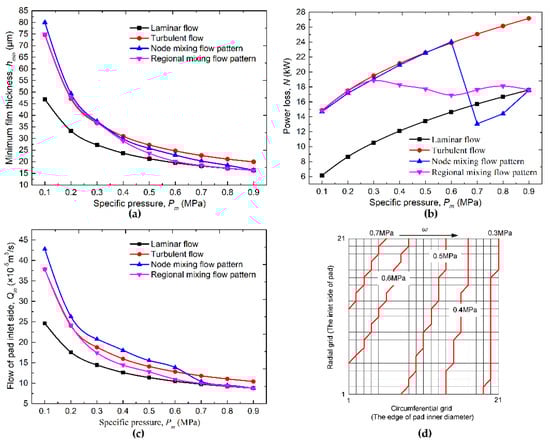
Figure 6.
The lubrication performance obtained under four kinds of flow pattern modes (300 r/min, specific pressure changes): (a) minimum film thickness, (b) power loss, (c) flow of pad inlet side, and (d) boundary line of laminar flow and turbulent flow.
4. Control of the Bearing Flow Pattern Region
This section proposes a method for controlling the flow distribution by changing the film thickness distribution, which is realized by changing the shape of the pad surface. As shown in Figure 7, the shape of the pad surface can be expressed by a quadratic arch surface equation [24]:
where R1 and R2 are the inner and outer radii of the pad, respectively, and r, θ, and z are the radial, angular, and vertical coordinates, respectively.
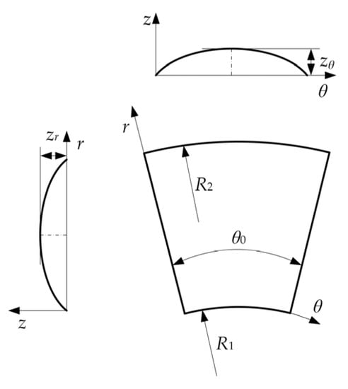
Figure 7.
Characterization of pad surface.
Six surface profiles of the pad based on the combination of the individual crowns zθ and zr are listed in Table 3. Additionally, the geometries of the pads are shown in Figure 8.
Table 3.
Definition and classification of the characteristics of the pad surface profile and crown.
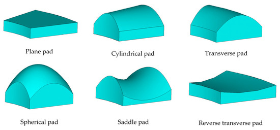
Figure 8.
Geometries of the pads.
Considering the shape of the pad surface, the equation of the bearing film thickness can be written as:
where zz is the axial height of the pad surface at the fulcrum.
5. Discussion
The flow region distribution of four kinds of pads is shown in Figure 9. The values of Δc determine the locations of the transition lines, thereby changing the area of the laminar and turbulence flow regions. As a consequence, the cylindrical pad, saddle pad, and spherical pad increase the turbulent flow area. These three kinds of surface topographies will increase the water film thickness and the flow rate. The effect of the saddle pad on improving the lubrication performance was the most obvious. The turbulent flow area was reduced by the transverse pad, which was disadvantageous to the increase in the film thickness.
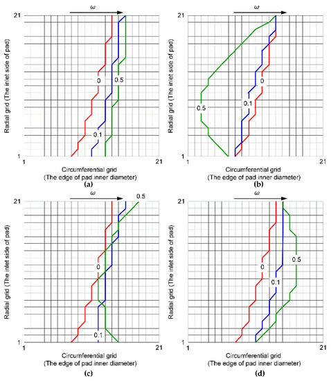
Figure 9.
Boundary line of laminar flow mode and turbulent flow mode (Δc changes): (a) cylindrical pad, (b) transverse pad, (c) spherical pad, and (d) saddle pad.
The lubrication performance of the six pads is shown in Figure 10. It can be seen that the cylindrical pad, saddle pad, and reverse transverse pad could increase the fulcrum film thickness, and the saddle pad had the most significant effect on the increase in the film thickness. The fulcrum film thickness of the transverse pad was obviously reduced, and the load-carrying capacity was weakened. Although the spherical pad was beneficial to increasing the fulcrum film thickness when Δc was small, with the increase in Δc, the fulcrum film thickness decreased to even lower than that of the plane pad. Compared with the other pads, the power loss and maximum film pressure of the spherical pad would be the largest. The power loss and maximum film pressure of the saddle pad were close to those of the plane pad, but the flow increased significantly. The cylindrical pad was found to be mediocre.
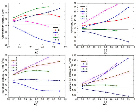
Figure 10.
Effects of crown parameters on the lubrication performance: (a) fulcrum film thickness, (b) frictional power loss, (c) flow of pad inlet side, and (d) maximum film pressure.
The simulation example shows that it is feasible to adjust the flow pattern by changing the pad shape. The circumferential bulge (zθ > 0) and radial concave (zr < 0) of the pad’s surface are beneficial for increasing the turbulent area, which will obviously improve the load-carrying capacity. In addition, the performance of the six pads changed accordingly with the degree of convexity and concavity. The performance seemed to be related to the fluid property of the pad itself. However, the minimum film thickness of the cylindrical pad showed an extreme fluctuation with the change in Δc. When Δc was 0.7, the minimum film thickness was the largest. This means that an excessive value of Δc will hinder the water flow on the pad’s surface, thereby affecting the formation of the water film.
6. Conclusions
Aiming at the mixing flow pattern of a WTTB, a regional mixing flow pattern and an isolated partition iterative algorithm are proposed, the thermoelastic dynamics lubrication performance of the WTTB is analyzed, and a method for the control of flow pattern is created. Our conclusions are as follows:
- The lubrication performances obtained under the four flow pattern modes were quite different, and the values of the mixing flow pattern were between those of the laminar and turbulent flow patterns. This shows that it is very important to choose a suitable flow pattern mode for the design of the WTTB.
- With a change in the speed or load, the area of the laminar and the turbulent flows at the bearing interface will change correspondingly, but the single flow pattern cannot reflect the transition phenomenon. The regional mixing flow pattern can automatically degenerate into a single flow pattern with the change in the operation conditions, which makes it more suitable for the WTTB under variable operation conditions.
- The calculation example shows that both the circumferential bulge and radial concave pad surfaces are beneficial for increasing the turbulent area of the pad and the film thickness, thereby improving the load-carrying capacity. Additionally, it is feasible to adjust the flow pattern by changing the pad shape. The method proposed in this paper can be used as a reference for bearing design procedures.
7. Outlook
The regional flow control method proposed in this paper can predict the performance of a WTTB under all operating conditions. It is of great significance for bearing applications such as marine thrusters and pumps with varying loads. The method proposed in this paper can be used as a reference for bearing design procedures. Regrettably, due to the limitations of the measurements, experiments cannot be carried out to verify the method described above. The regional feature test involves the measurement of the film thickness in different regions of the pad surface. Accurate film thickness measurement has been a hot point of bearing research. In light of the limited installation space of sensors, the ultrasonic method may be a good choice. Ultrasonic sensors are mounted in an array on the back surface of the pad. The echo signals are processed by the ultrasonic reflection coefficient amplitude spectrum to obtain the film thickness information of each point. However, the ultrasonic method also has certain limitations (e.g., the interference of echo signals between multiple sensors and signal attenuation in multilayer materials).
Author Contributions
Conceptualization, W.O. and J.H.; methodology, W.O.; software, W.O. and B.W.; validation, W.O. and B.W.; formal analysis, W.O.; investigation, B.W.; resources, W.O.; data curation, J.H.; writing—original draft preparation, W.O. and B.W.; writing—review and editing, J.H. and B.W. All authors have read and agreed to the published version of the manuscript.
Funding
This research was funded by the National Key Research and Development Project of China (No. 2018YFE0197600), National Natural Science Foundation of China (grant number 52071244), and Self-Determined and Innovative Research Funds of WUT (grant number 2021-IVA-004B).
Institutional Review Board Statement
Not applicable.
Informed Consent Statement
Not applicable.
Data Availability Statement
Some data used during this study are available from the corresponding author upon request.
Conflicts of Interest
The authors declare no conflict of interest.
References
- Yan, X.P.; Liang, X.X.; Ouyang, W.; Liu, Z.L. A review of progress and applications of ship shaft-less rim-driven thrusters. Ocean Eng. 2017, 144, 142–156. [Google Scholar] [CrossRef]
- Wang, Z.; Ying, L.; Wang, Y.; Liu, X.; Wang, Y. Influence of squeezing and interface slippage on the performance of water-lubricated tilting-pad thrust bearing during start-up and shutdown. Lubr. Sci. 2018, 30, 137–148. [Google Scholar] [CrossRef]
- Liang, X.X.; Yan, X.P.; Ouyang, W.; Liu, Z.L. Experimental research on tribological and vibration performance of water-lubricated hydrodynamic thrust bearings used in marine shaft-less rim driven thrusters. Wear 2019, 426, 778–791. [Google Scholar] [CrossRef]
- Gardner, W.W.; Ulschmid, J.G. Turbulence effects in two journal bearing applications. J. Tribol. 1974, 96, 15–20. [Google Scholar] [CrossRef]
- Chu, W.J.; Hu, H.C.; Zhang, Y.Y. An experimental investigation on transition region from laminar to turbulent flow of oil film in journal bearing. J. Xi’an Jiaotong Univ. 1992, 26, 17–24. [Google Scholar]
- Zhang, S.L.; Wei, Y.G.; Li, R.Z.; Hong, G. Visual experimental research on oil flow state of step hydrodynamic bearing. Lubr. Eng. 2014, 39, 31–34. [Google Scholar]
- Constantinescu, V.N. Basic relationships in turbulent lubrication and their extension to include thermal effects. J. Lubr. Technol. 1973, 95, 147–154. [Google Scholar] [CrossRef]
- Ng, C.W.; Pan, C.H.T. A Linearized Turbulent Lubrication Theory. J. Fluid Eng.-T ASME 1965, 87, 675–688. [Google Scholar] [CrossRef]
- Elrod, H.G.; Ng, C.W. A theory for turbulent films and its application to bearings. J. Fluid Eng.-T ASME 1967, 86, 346–362. [Google Scholar] [CrossRef]
- Bou-Said, B.; Nicolas, D. Effects of misalignment on static and dynamic characteristics of hybrid bearings. Tribol. T 1992, 35, 325–331. [Google Scholar] [CrossRef]
- Kosasih, P.B.; Tieu, A.K. An analysis of sector-shaped thrust bearings operating in the transition regime. Wear 1993, 160, 291–299. [Google Scholar] [CrossRef]
- Bouard, L.; Fillon, M.; Frene, J. Comparison between three turbulent models-Application to thermohydrodynamic performances of tilting-pad journal bearings. Tribol. Int. 1996, 29, 11–18. [Google Scholar] [CrossRef]
- Wang, X.J.; Su, H.; Zhang, Z.M. Study on the performce of journal bearing in turbullt regime with the combined Reynolds stress model. Chin. J. Mech. Eng.-EN 2003, 39, 85–89. [Google Scholar] [CrossRef]
- Jean, F.; Arghir, M.; Constantinescu, V. Combined thin-film and Navier-Stokes analysis in high Reynolds number lubrication. Tribol. Int. 2006, 39, 734–747. [Google Scholar]
- Shenoy, S.B.; Pai, R. Theoretical investigations on the performance of an externally adjustable fluid-film bearing including misalignment and turbulence effects. Tribol. Int. 2009, 42, 1088–1100. [Google Scholar] [CrossRef]
- Bendaoud, N.; Kadda, M.; Youcefi, A. Numerical analyses of turbulent flow behavior in plain journal bearing. Ind. Lubr. Tribol. 2016, 68, 76–85. [Google Scholar] [CrossRef]
- Lv, F.R.; Jiao, C.X.; Ta, N.; Rao, Z.S. Mixed-lubrication analysis of misaligned bearing considering turbulence. Tribol. Int. 2017, 119, 19–26. [Google Scholar] [CrossRef]
- Capitao, J.W. Influence of turbulence on performance characteristics of the tilting pad thrust bearing. J. Tribol.-T ASME 1974, 96, 110–117. [Google Scholar] [CrossRef]
- Pap, B.; Fillon, M.; Guillemont, M.; Bauduin, L.; Chocron, J.; Gédin, P.; Biadalla, L. Experimental and numerical analysis on the seizure of a carbon-filled PTFE central groove gournal bearing during start-Up Period. Lubricants 2018, 6, 14. [Google Scholar] [CrossRef] [Green Version]
- Safar, Z.; Szeri, A.Z. Thermohydrodynamic lubrication in laminar and turbulent regimes. J. Tribol.-T ASME 1974, 96, 48–57. [Google Scholar] [CrossRef]
- Gong, J.Y.; Jin, Y.; Liu, Z.L.; Jiang, H.; Xiao, M. Study on influencing factors of lubrication performance of water-lubricated micro-groove bearing. Tribol. Int. 2019, 129, 390–397. [Google Scholar] [CrossRef]
- Katsaros, K.P.; Nikolakopoulos, P.G. On the tilting-pad thrust bearings hydrodynamic lubrication under combined numerical and machine learning techniques. Lubr. Sci. 2021, 33, 153–170. [Google Scholar] [CrossRef]
- Kirillov, P.L.; Ninokata, H. Heat transfer in nuclear thermal hydraulics. In Thermal-Hydraulics of Water Cooled Nuclear Reactors; D’Auria, F., Ed.; Woodhead Publishing: Sawston, UK, 2017; pp. 357–492. [Google Scholar]
- Yuan, X.Y.; Zhu, J.; Chen, Z.L.; Wang, H.L.; Zhang, C. A three-dimensional TEHD model and an optimum surface profile design of pivoted pad thrust bearings with large dimensions. Tribol. T 2003, 46, 153–160. [Google Scholar] [CrossRef]
Publisher’s Note: MDPI stays neutral with regard to jurisdictional claims in published maps and institutional affiliations. |
© 2022 by the authors. Licensee MDPI, Basel, Switzerland. This article is an open access article distributed under the terms and conditions of the Creative Commons Attribution (CC BY) license (https://creativecommons.org/licenses/by/4.0/).