Article

An Experimental Demonstration of MIMO C-OOK Scheme Based on Deep Learning for Optical Camera Communication System

Department of Electronics Engineering, Kookmin University, Seoul 02707, Korea
*
Author to whom correspondence should be addressed.
Appl. Sci. 2022, 12(14), 6935; https://doi.org/10.3390/app12146935
Submission received: 25 May 2022 / Revised: 21 June 2022 / Accepted: 7 July 2022 / Published: 8 July 2022

Abstract

:
Currently, wireless communication systems that use radio frequency are commonly deployed, for example, mobile communication systems, satellite systems, and the Internet of Things (IoT) systems. Based on their easy installation, wireless communication systems have benefits over other wired communication systems. However, using high frequencies to transfer data via wireless communication can hold significant risks for human health. Several researchers have studied this topic using visible light instead of Radio Frequency (RF) waveforms in communication systems. Many potential approaches are relevant in this regard, i.e., visible light communication, light fidelity, free-space optical, and optical camera communication. Artificial intelligence is also influencing the future of industry and people and is used to solve complex problems, create intelligent solutions, and replace human intelligence as the driving force behind emerging technologies such as big data, smart factories, and the IoT. In this paper, we proposed the architecture of the MIMO C-OOK (Multiple-Input Multiple-Output Camera On–Off Keying) scheme, which uses a convolutional neural network for light-emitting diode detection and a deep learning neural network for threshold predictions considering long-distance communication and mobility support. Our suggested method aimed to improve the performance of the traditional camera on–off keying scheme by increasing data rate, communication distance, and low bit error rate. Our suggested technique may achieve a communication distance of up to 22 m with a low error rate when considering the mobility impact (2 m/s, i.e., walking velocity) by controlling the exposure time, focal length, and employing Forward Error Correction code.

1. Introduction

Wireless communication systems have many advantages compared with their wired counterparts, including easy setup, flexibility, and delivering broadcasting information without cables. Wireless systems using radio frequencies (RFs) are broadly used in communication networks. However, RF waves can become exhausted during the formation process of wireless communication technology. To increase the data rate, the communication frequencies must be increased. Many research groups and organizations have investigated ways by which to improve sixth-generation (6G) cellular networks in the sub-THz waveband, which promises a data rate of up to 1–10 Tbps [1]. However, to communicate information, an RF system employs electromagnetic waves that are potentially harmful to human health [2]. This issue must be carefully considered in settings that include the elderly, teenagers, and patients, e.g., nursing homes, schools, and hospitals.
Researchers worldwide are looking for new technologies that can substitute RF techniques in specific applications owing to the potentially detrimental effects of these systems. The use of visible light to transfer data has emerged as a viable alternative to RF methods. Optical Wireless Communication has many candidate solutions, some of which are as follows: Visible Light Communication (VLC), Light Fidelity (LiFi), Free-Space Optical (FSO), Optical Camera Communication (OCC), etc. The advantages of OWC systems over the RF approach are as follows:
  • The human body is unaffected by visible light waves [3]. In addition to the negative impact of RF waves on human health, they can also degrade system performance owing to electromagnetic interference (EMI).
  • Visible light waveforms have a much larger bandwidth compared with RF waves (more than 1000 times that of RF waveforms).
  • Visible light waveforms are safer and more efficient when the line-of-sight transmission is acquired by the optical channel.
  • Based on the following benefits, several organizations have suggested research funding to develop and investigate OWC systems. The OWC approach was introduced with its complexity protocol in the Institute of Electrical and Electronics Engineers (IEEE, 2011) 802.15.7-2011 standard [4]. The IEEE 802.15.7-2018 [5] standard was published in 2018, and it added the following four modes to the previous standard.
  • The IEEE 802.15.7-2011 standard [4] included VLC modes information.
  • Optical Camera Communication: By using image sensors, modulation systems can decode OCC information from a variety of LED sources.
  • High-speed LiFi: Using high-rate photodiode modulation techniques, the data rate can be increased to higher than 1 Mbps.
  • Photodiode identification: Photodiodes are used in communication techniques to transmit data at a low rate (less than 1 Mbps).
Based on innovative manufacturing technologies, light-emitting diodes (LEDs) have several benefits as next-generation light sources with specific potential. These advantages include long life, efficient power consumption, low cost, and a variety of sizes. Additionally, LEDs are compatible and useful with high-rate OWC technologies, which enables ON/OFF status-switching at a high frequency [6,7,8]. For LiFi and VLC, photodiodes have been used as detectors [4], which can receive the intensity values of transmitters in real-time. In the case of OCC, a camera was used as a detector, which captured images and decoded data derived from LEDs. Global and rolling-shutter cameras are two general types that are deployed in OCC technologies. Accordingly, suitably designed OCC modulation schemes can be developed.
RF systems are used in a variety of current applications including communication, monitoring, and mobile communication systems. These systems generate EMI, which can impact human health and especially brain function [9,10]. As noted, OWC technologies have attracted significant research interest worldwide because it is EMI-free and, accordingly, is a good candidate for replacing RF technology [11]. In VLC and LiFi technologies, photodiodes receive information at an intensity that is based on the ON/OFF status of the light sources in the transmitter [12]. In [13,14], a photodiode-based ultra-high-speed pulse-density modulation with exceptionally effective spectrum characteristics was proposed. Multiple-input multiple-output (MIMO) is a technology proposed in [15,16] to enable large data rate transfers using ultra-high-speed multi-channels.
As noted, VLC/LiFi/FSO systems employ photodiodes as detectors. These present some disadvantages. For example, they can only be employed for short-distance applications and are extremely sensitive to the mobility effect. Outdoor environments can also cause problems for an LED signal aimed at receiving signals from photodiodes. Using the OCC technique, however, a longer communication distance (up to 200 m) could be achieved [17] because an image sensor is used rather than photodiodes. In [18], Nguyen et al. considered how image sensor types affected an OCC system. When using a global shutter camera, the frame rate of the camera will affect the data rate of an OCC system according to Nyquist’s law. Therefore, when using a rolling-shutter camera, the frame rate and the rolling-shutter speed of the camera should be considered. In [18], the authors noted the effects of the camera’s focal length and the exposure time on communication distance. Currently, LiFi technology can be deployed at a 10 m communication distance in an outdoor environment using a photodiode lens (2 inches) [19].
Region of interest (RoI) signaling was proposed and standardized [5] in PHY IV (IEEE 802.15.7-2018), which was deployed to detect multiple LEDs in an OCC system. The document [20] introduced the camera on–off keying (C-OOK) scheme, which can sustain a high data rate. This scheme was also standardized in IEEE 802.15.7-2018. However, the C-OOK scheme has some drawbacks, e.g., a high bit error rate (BER) and a short communication distance [21]. A proposed MIMO C-OOK technique that achieve a long distance with a lower BER value was achieved by using a matched filter. In [22], we proposed a rolling-shutter orthogonal frequency-division multiplexing (OFDM) scheme for a high data-rate OCC system. Depending on the rolling-shutter effect of the camera, the OFDM waveform could be received according to the LED intensity values in each image. The 2D OFDM scheme for a screen-to-camera technique was developed by Nguyen et al. [23] with a data rate of more than 50 kbps. This scheme has the following disadvantages: large transmitter size, short communication distance, and an expensive transmitter achieving a high data rate.
“Deep learning” is known as a subset of machine learning techniques based on artificial neural networks that support some notions for resolving OCC problems including accurate object detection, robustness, high data rate, and real-time processing for mobile environments. In [24], version 5 of the You Only Look Once (YOLOv5) algorithm was proposed to optimize the hyperparameters in a real-time process for Underwater Detection. The optical fringe codes (OFC) proposed for OCC, based on a convolution neural network (CNN) with 95% precision, are presented in [25]. However, the mobility effect was not considered.
In the present work, we propose an LED detection method based on deep learning using the YOLOv5 algorithm to achieve high accuracy (detection accuracy of more than 97%) in a real-time process for a C-OOK scheme. Additionally, a deep learning decoder was also proposed to increase the OCC performance compared with the conventional decoder [21] method.
The remainder of this study comprises four sections. In Section 2, we explain the contributions of the study, i.e., using deep learning to improve the OCC performance. Section 3 illustrates the system architecture of the MIMO C-OOK scheme using deep learning. The study’s implementation results are described in Section 4, and the conclusion of this study is discussed on Section 5.

2. The Contribution of the Present Study

In this paper, we proposed a deep learning approach based on LED detection and data decoding for a MIMO C-OOK scheme to improve the data rate and decrease the BER in a harsh environment that considers long-range and mobility effects. Our scheme presents several advantages as outlined below.
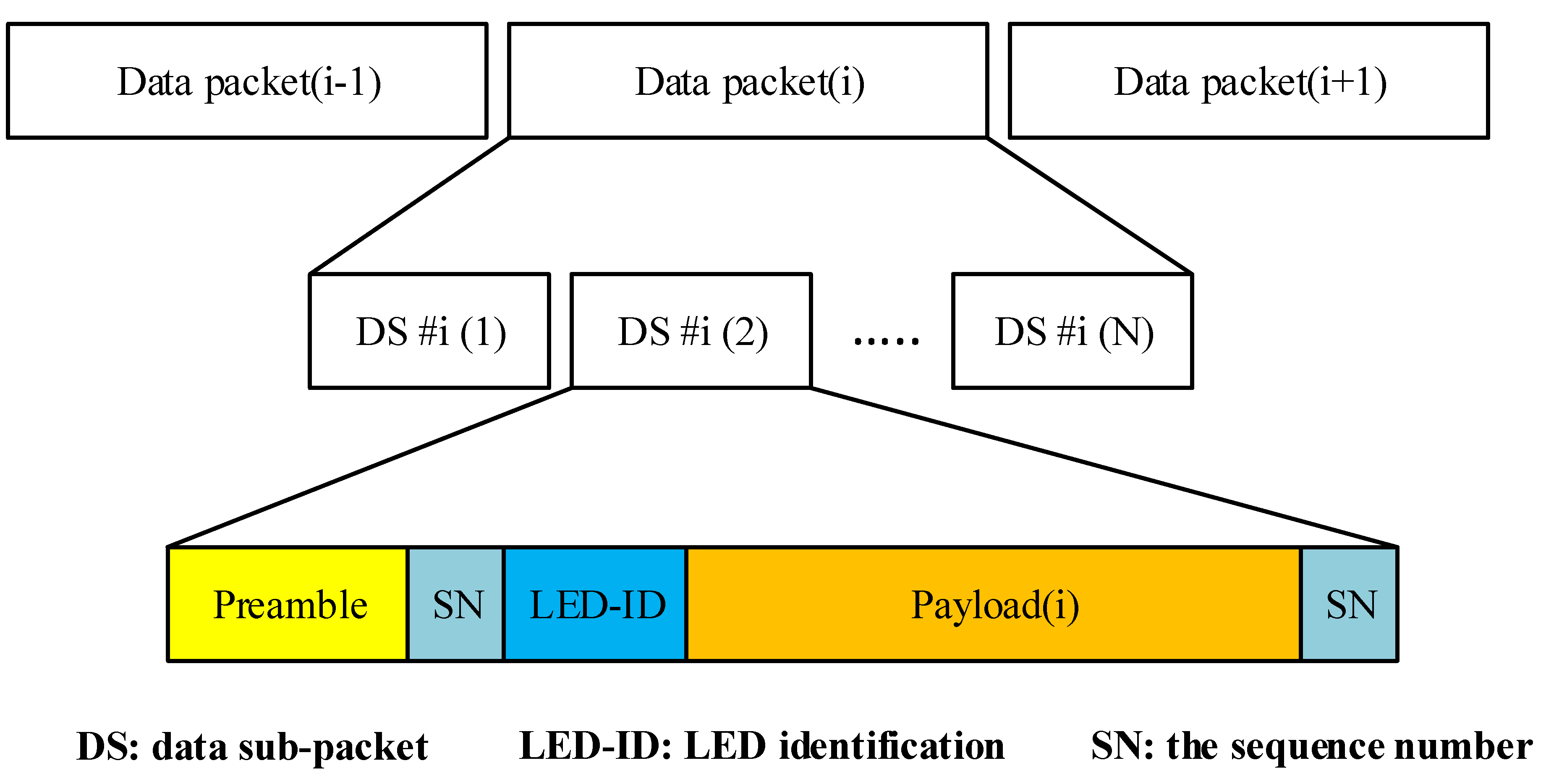
  • Support for frame rate variations: Frame rate variation significantly impacts the OCC system, causing packet losses on the receiver side. Most people tend to ensure that a camera frame rate remains constant regardless of its specifications (e.g., 30 or 1000 fps). Depending on the technological parameters of different cameras, synchronizing transmitters and receivers can be difficult. Then, the sequence number (SN) is used to improve the system’s performance by identifying whether the camera frame rate is higher than the transmitter’s package rate.
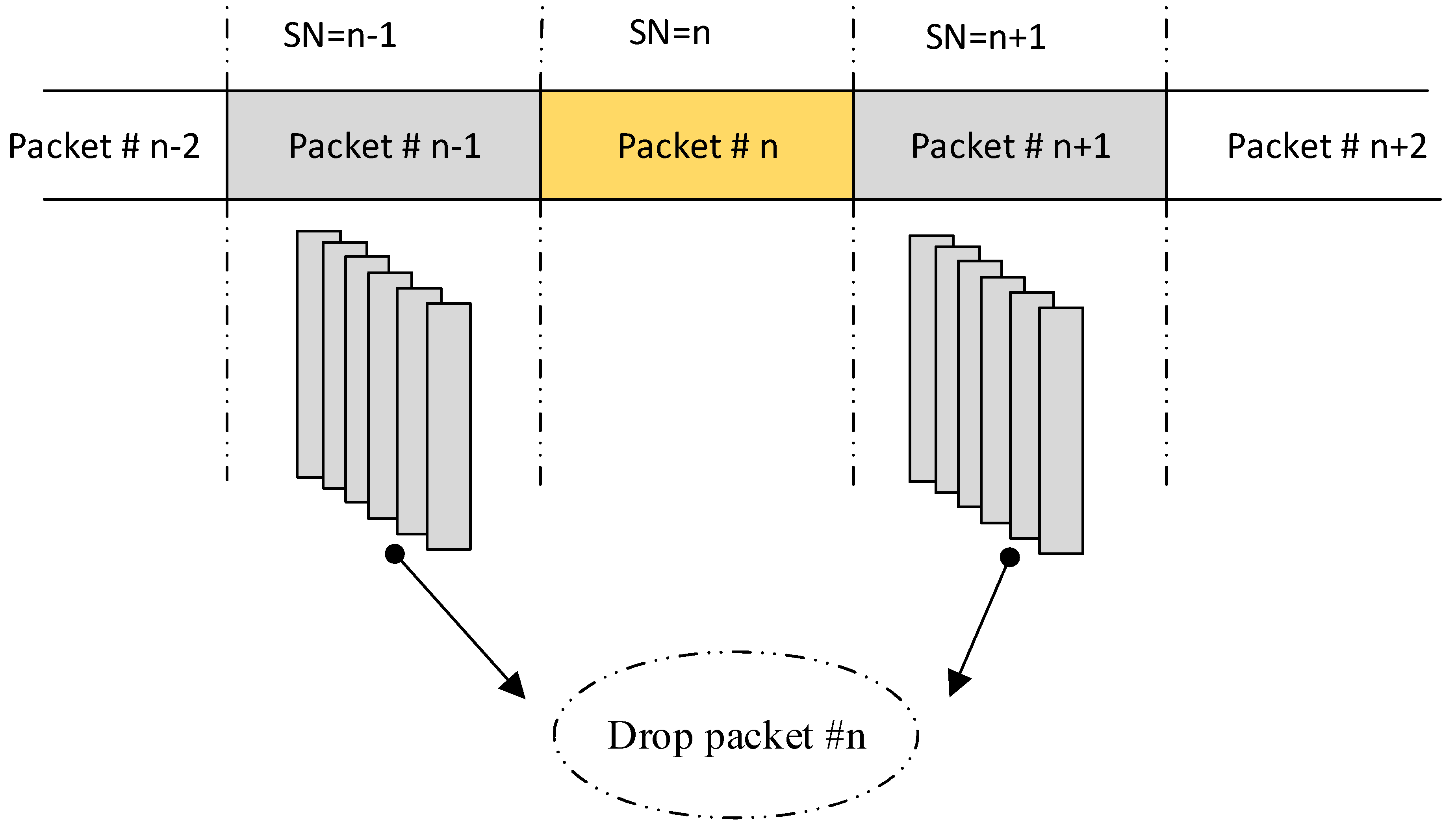
  • The discovery of lost packets: To detect the missing packet, we compared two SNs in two consecutive pictures when the length of the SN exceeded a specified value to discover each missing packet collected by the camera.
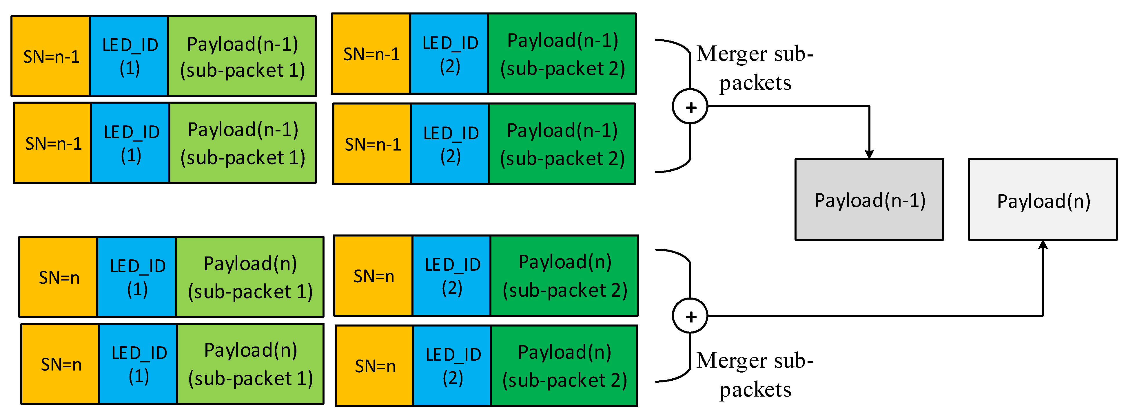
  • Data-merging algorithm: We presented this process for each data sequence in our experiment by deploying the sequence number in each packet to detect the exact sequence of packets.
  • Improved data rate: By applying deep learning, many LEDs could be detected with high accuracy by considering long-range and mobile environments compared with RoI algorithms.
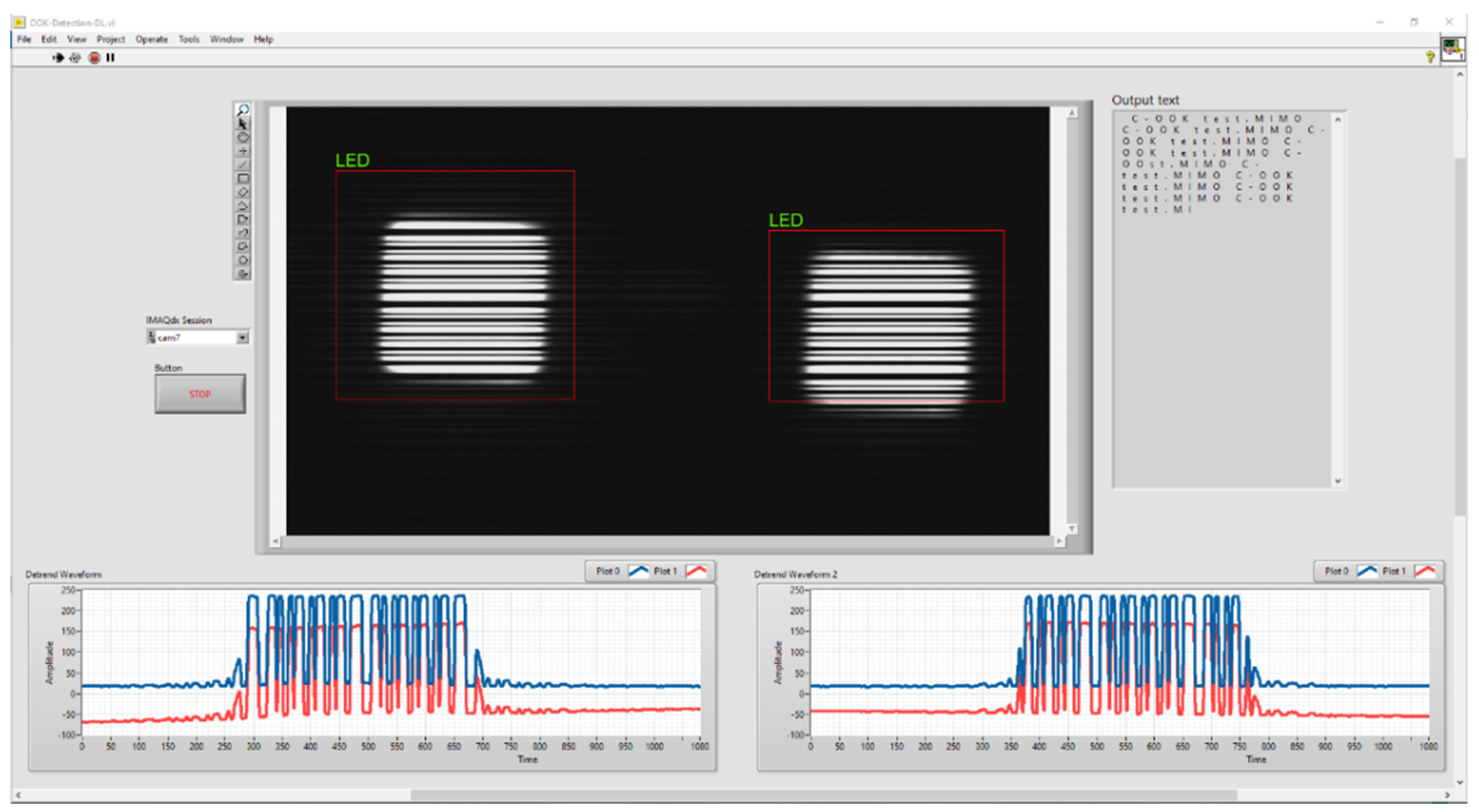
  • Mobility support: The C-OOK scheme based on the rolling-shutter effect, which was more sensitive to the mobility effect than RoI algorithms, highlighted issues for detecting multiple LEDs compared with CNN. When using a rolling-shutter camera, the LEDs were displayed in an image as black and white strips; the number of LEDs could not be clearly detected when using RoI algorithms. Accordingly, we proposed a neural network for improving the performance of the OCC system.
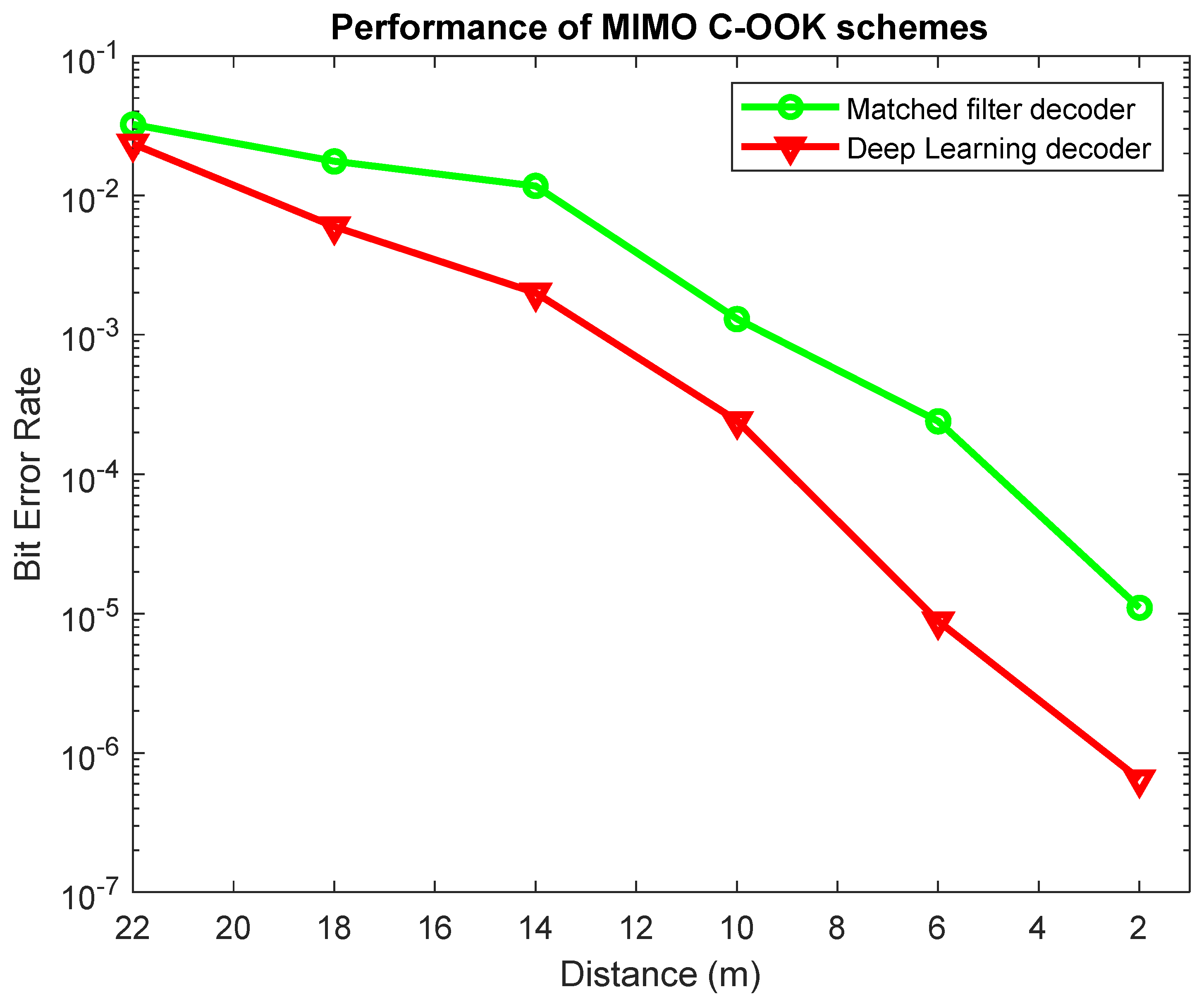
  • The BER was reduced compared with that using the conventional decoder approach. By collecting data from several cases (using different distances, mobility, and from several cameras), the dataset for a deep learning neural network decoder could achieve good performance compared with using the conventional decoder method. A comparison between the conventional decoder method and our proposed technique based on deep learning is shown in Section 4.

3. System Architecture

An OCC system’s fundamental principle is to control the intensity with which optical signals transmit and receive data and improve the system’s communication performance using promising modulation techniques. The simplest and most well-known modulation method for amplitude-shift keying modulation is OOK, which transmits data using two statuses, “on” and “off,” which are signified by “1” and “0” bits, respectively. In this study, we proposed the details for a MIMO C-OOK modulation scheme based on deep learning for data detection and decoding. Using deep learning, the performance of an OCC system was improved compared to that of existing techniques. Figure 1 shows the architecture of the MIMO C-OOK-based deep learning model. On the transmitter side, we used multiple LEDs to transmit data, and only a single camera received data from multiple LEDs based on Deep Learning detection and tracking.

3.1. Deep Learning for Detecting and Tracking LEDs

In the OCC system, RoI algorithms are well-established. In most RoI methods with real-time processing for object detection, both object and feature-based detection approaches are deployed. As previously noted, with the rolling-shutter effect, LEDs are shown in images represented by black and white strips corresponding to “0” and “1” bits. Each image includes many strips, which creates problems for RoI detection, particularly as it concerns the mobility effect. Deep learning neural networks are well-established methods for computer vision applications, e.g., object detection, image classification, localization, and image reconstruction. CNNs have emerged as good candidates for deep learning-based computer vision applications. The CNN-based YOLO algorithm is a state-of-the-art, real-time object detection system. In this paper, we proposed the customization and training of YOLO models for LED detection and tracking considering the rolling-shutter and mobility effects.
The experimental dataset was collected using real traffic scenes to verify the performance of our LED detection and recognition method. We recorded daytime and nighttime video footage with the mobility effect and generated 1000 blurry and clear images at different exposure times. Using this image dataset, we labeled images and trained the YOLOv5 model, which was modified with 5/7 convolution layers. Only one detection class was included. The corresponding number of filters in the final number of convolution layers was 40.

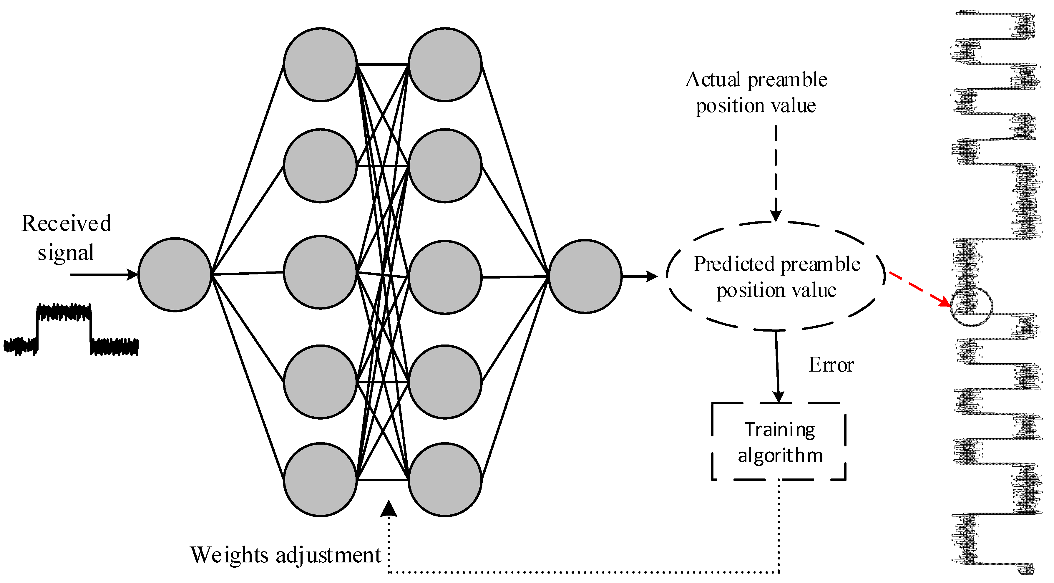
3.2. Decoding Based on Deep Learning

The relationship between signal-to-noise (SNR) and communication distance is described in Section 4. The SNR values are smaller if the communication distance is long. Therefore, the receiver side experiences challenges in terms of defining the threshold between ON and OFF values. In [21], we proposed the matched filter method to optimize the SNR values and increase the communication distance. However, the matched filter did not perform well in a mobile environment, which is discussed in Section 4.
The zero-crossing filter, developed in [21], separates ON/OFF levels at the receiver side using zero as the threshold level. When the system’s SNR is high, this approach performs well, as shown in Figure 2a; however, when this value is low, distinguishing between ON/OFF statuses is difficult as illustrated in Figure 2b. The matched filter is a filter technique that determines the template signal in the real signal by comparing it to a template signal [21]. With additional random noise, the matched filter (a linear filter technology) maximizes the SNR. The matched filter has advantages when the SNR is small but does not work well for mobility channels as shown in Section 4. The blur effect occurs when the transmitter and receiver are move relative to one another. This creates inter-symbol interference for the OCC system, causing a reduction in the system’s performance. A deep learning neural network was applied to detect a preamble and decode data by considering the mobility effect. In this paper, Root mean square error (RMSE) was applied to evaluate the error evaluation metrics for the proposed scheme. With 200 epochs, it can achieve high accuracy for the forecasting value error with low values (<0.1).
After detecting the LEDs, the OCC signal was selected from multiple LEDs in the LED region using the down-sampling algorithm. The C-OOK signal was detected by extracting the central intensity point of the LEDs. The preamble was detected by the neural network as show in Figure 3.
The raw data (10,000 samples) were collected by the rolling shutter camera at different distances (2 m, 6 m, 10 m, 16 m, and 22 m) at different velocity speeds, including the preamble and the payload parts. To avoid overfitting the model, we used a basic deep learning neural network model with two hidden layers. Following preamble detection, we were able to reliably detect the start of frame of C-OOK signals, which improved the OCC system performance compared with the conventional technology in mobility environment. In the case of overfitting, the accuracy of the test dataset is undermined when there are six or more hidden layers.

3.3. Channel Coding

In many digital communication systems, channel coding is a critical component. It is also known as a forward error control approach in digital systems for detecting and reducing bit errors. Channel coding can be employed on both the transmitter and receiver sides to increase system reliability. Channel coding is deployed on the transmitter side to encode raw data by adding additional bits prior to modulation. On the receiver side, however, channel coding is employed to decode data. The bit error can easily be discovered and fixed using channel coding. The relevant channel coding was used in our experiment, based on the length of the MIMO C-OOK sub-packet.

4. Implementation

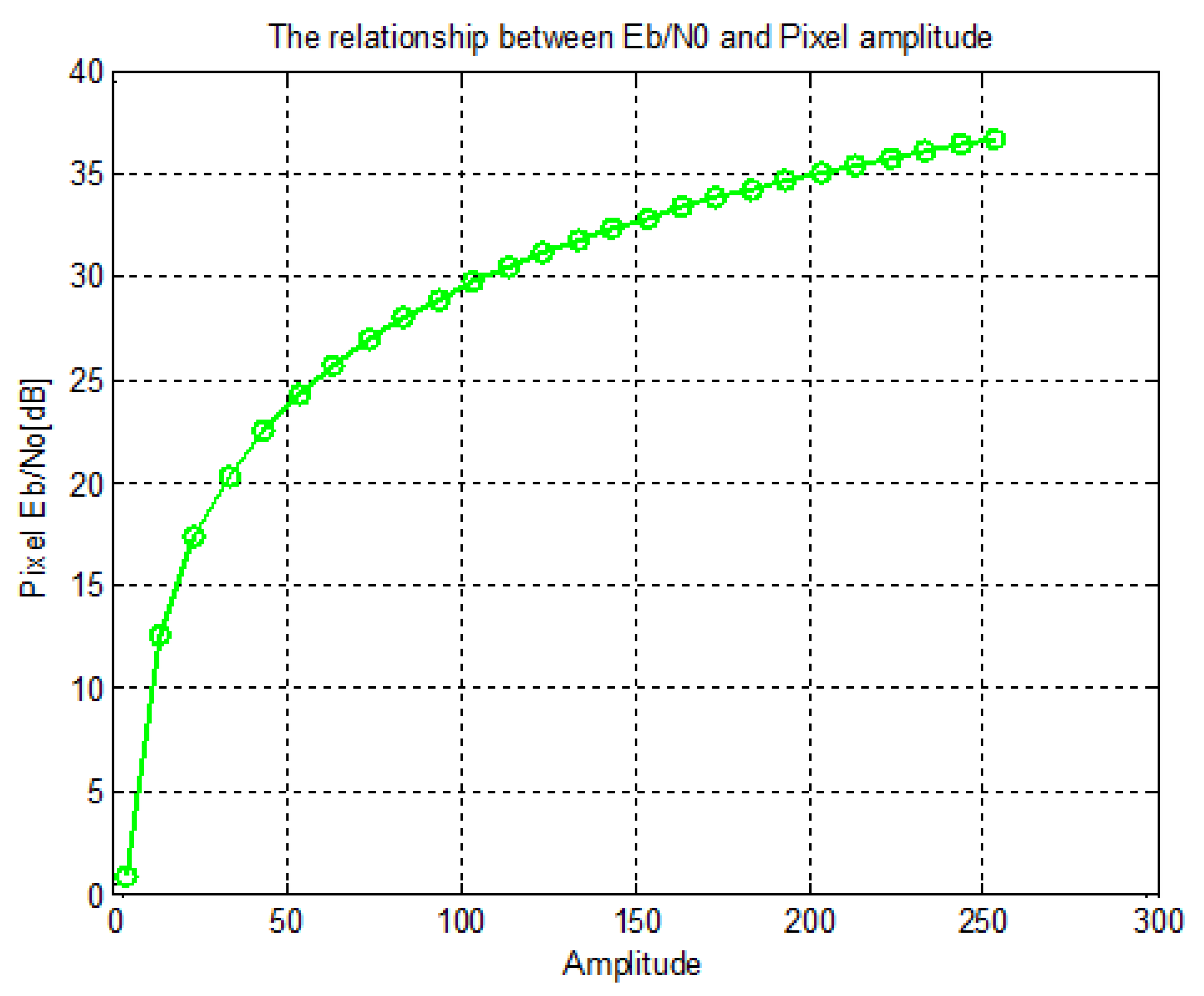
4.1. The Pixel Energy Per Bit to the Spectral Noise Density Ratio Computation and Noise Modeling

The pixel noise in the CCD/CMOS cameras is approximated [22] using Equation (1) as follows:
n ~ N ( 0 , δ ( s ) 2 )
where s is the value of a pixel, δ 2 ( s ) = s a α + β , a is the “1” and “0” amplitude, and α , β specify the fitting factors obtained in the experiments. Model-fitting coefficients were employed in our implementations and could be predicted experimentally [22]. Equation (2) [22] is used to calculate the pixel E b / N 0 on the receiver side, assuming that each symbol comprises one bit as follows:
P i x e l E b N 0 = E s 2 E n 2 a 2 · Δ a · α · Δ + β
where E b is the energy for each bit, N 0 is the noise density, s is the intensity pixel values, Δ = T exp o s u r e / T b i t refers to the camera exposure duration divided by the bit interval, and α , β are the fit parameters. The theoretical relationship between pixel E b / N 0 and image amplitude shown in Figure 4.

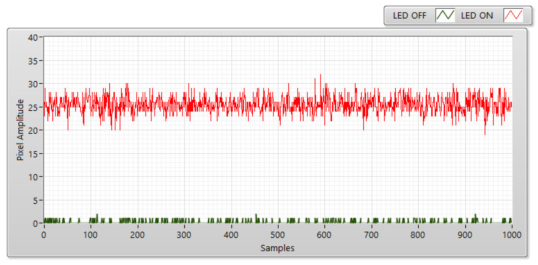
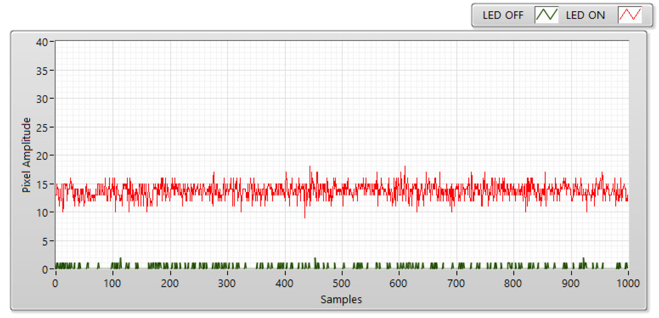
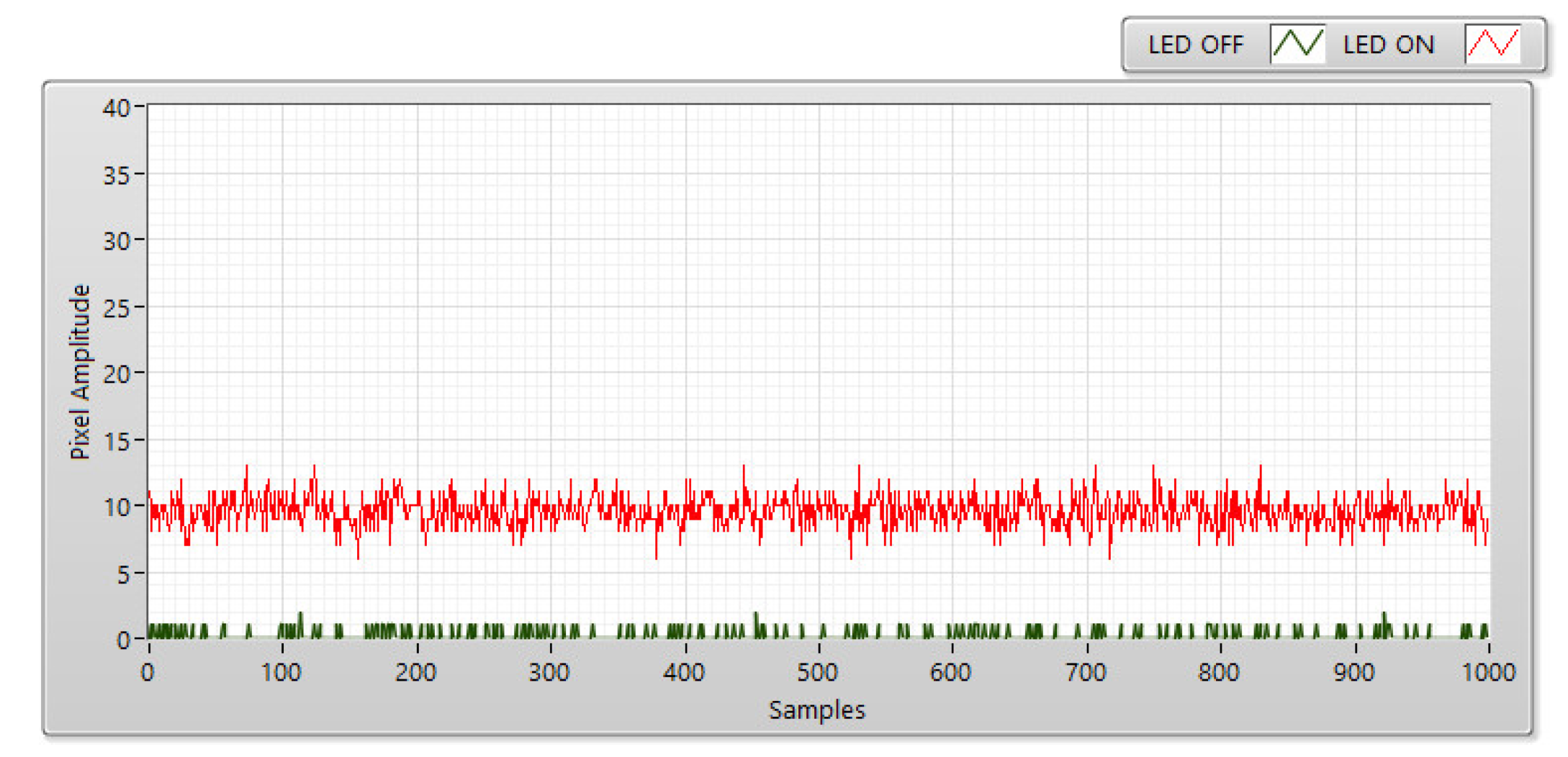
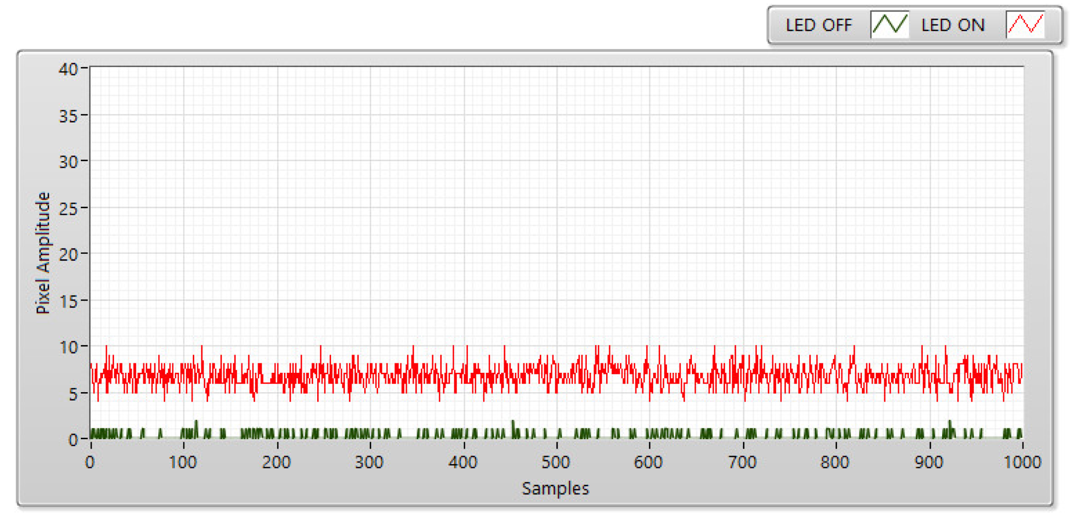
4.2. The Experimental SNR Measurement

The SNR measurements illustrate the link between communication distance, SNR, and exposure times. Additionally, the appropriate exposure period could be changed to obtain the desired BER value, as well as the OCC system’s communication distance. The SNR was measured during the trials using an LED (9 V DC-3W). The devices used in this experiment are shown in Figure 5. A rolling-shutter camera was set to exposure durations of 50–500 μs and communication distances of 5–20 m. In the model of the system, an LED (9 V DC-3W) was employed.
The Signal to Noise (SNR) values were measured at distances of 5, 10, 15, and 20 m for both the ON and OFF states of the LEDs. When LEDs are turned off, it is considered as background noise; the pixel amplitude SNR is shown by the green line in Figure 6, Figure 7, Figure 8 and Figure 9. The background noise depends on the noise of the optical environment, but it does not depend on exposure time or distance. When the LEDs were turned on, their signal power was considered; the SNR is presented as a red line with varying distances. The SNR in decibel (dB) was determined according to the measurement below.
S N R d B = 20 log 1 n i = 0 n 1 A i 2 1 n i = 0 n 1 B i 2
In Equation (3), B is the background noise, and A is the LED signal power. The number of samples measured is denoted by n . The camera’s received pixel intensity is larger when there is a shorter communication distance and lower with an extended communication distance. Furthermore, the SNR calculation was also affected by the exposure time as shown in Figure 10. In this case, the image sensor acted as a low-pass filter, which smoothed out the high-tone signal with longer exposure times. The communication bandwidth decreases as the exposure period increases, resulting in a reduction in the overall noise power dispersed over the bandwidth.
At a short distance, the received pixel intensity values are higher, while at a long distance, they are modest. As revealed in Figure 10, the shutter speed, distance, and camera exposure time also affect the SNR values. Figure 10 depicts the relationship between SNR and pixel intensity at 50, 100, 300, and 400 μs of exposure time.

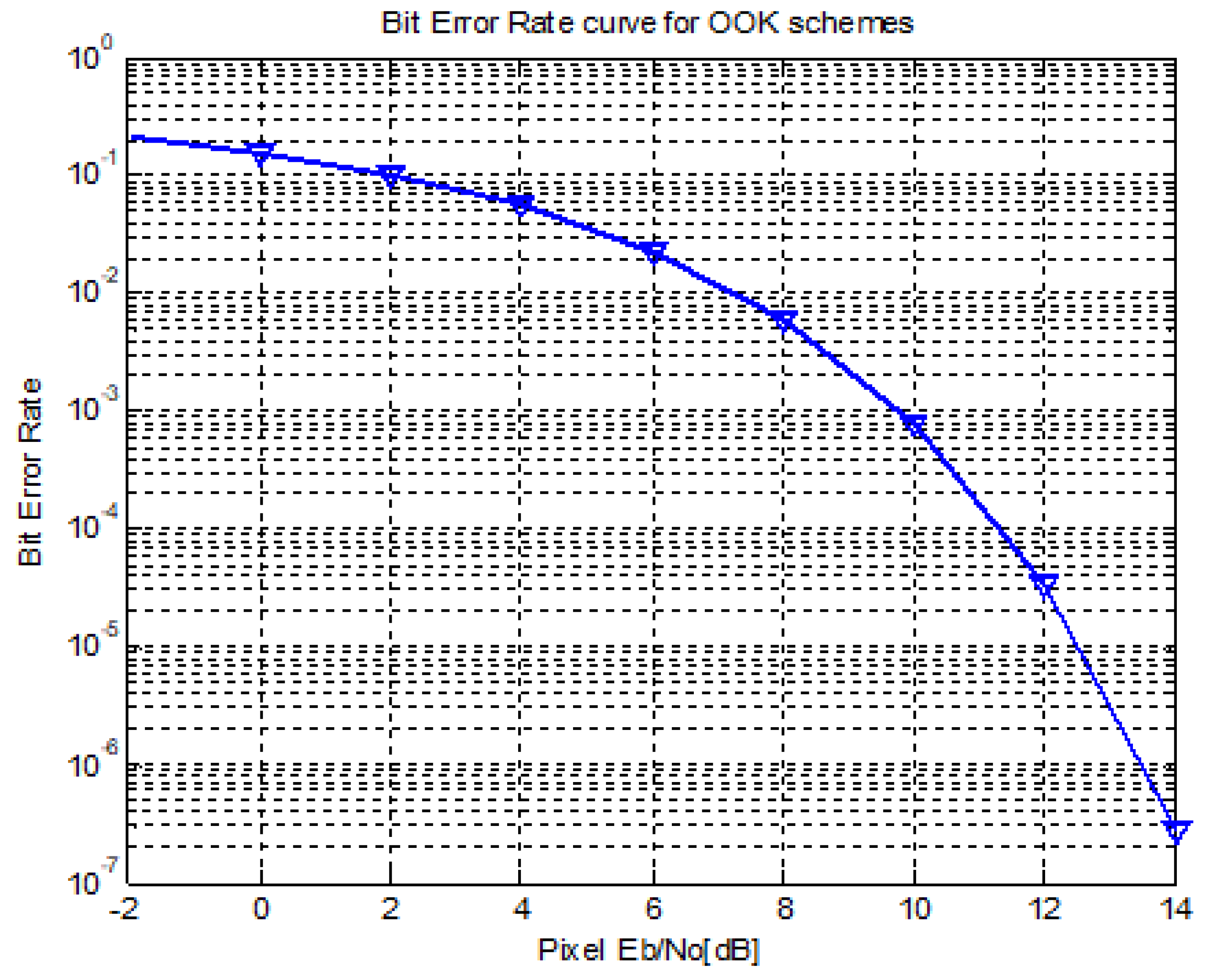
4.3. BER Estimation for the Optical on–off Keying Modulation

At the receiver side of the communication system, the electrical intensity of the signal is given as follows:
r ( t ) = I ( t ) + i = + I ( t ) a i g ( t i T s y m b o l ) + n ( t )
where a i is the level of the i th OOK symbol and a i ∈ {0,1}. We assumed that the probabilities of bits 0 and 1 were P 0 and P 1 , while g ( t ) is the rectangular function, and T s y m b o l represents the symbol duration. Since only AWGN is present in the optica channel model, the BER can be displayed [21] in Equation (5) as shown below.
P e = 1 2 erfc ( E b 2 σ n 2 )
Owing to the presence of only the AWGN channel, the OOK signal for bits 0 and 1 is presented as follows:
r ( t ) = n ( t ) , a i = 0 2 I ( t ) + n ( t ) , a i = 1
Figure 11 shows the bit error probability of the O-OOK modulation versus pixel energy per bit to noise density ratio in the AWGN channel. The figure shows that the optical OOK schemes require a pixel Eb/N0 of at least 11 dB to achieve a BER of 10 4 . By properly controlling the camera’s exposure period, the proposed system was able to obtain a BER of 10 4 at a distance of 20 m as shown in Figure 10. As shown below, we can improve the SNR by increasing the exposure time; however, it reduces the bandwidth of OCC system. As a result, the exposure time setting must be carefully evaluated in order to achieve better results and a suitable modulation scheme [26].

4.4. Implementation Results

Figure 12 shows the architecture adopted for the MIMO C-OOK scheme. Each packet includes the same sub-packets to support the frame rate variation effect. An SN was used to generate the sub-packet’s serial number. The data payload of each sub-packet in a contained packet was the same. In reality, SN is divided and managed according to the combination of the transmitter’s packet rate and the frame rate of the camera. Undersampling occurs if the frame rate is lower than the transmitter packet rate. Oversampling, by contrast, occurs when the frame rate exceeds the transmitter packet rate. The transmitter packet rate is defined as the number of packets that include various payloads and that are continuously transmitted in a given time (e.g., 60 packets/s). Data packet frames with a smaller number of data sub-packets (DSs) were included in the proposed data frame structure, and each DS included payload data and an SN. The SN included the data packet’s sequence information, as well as the payload’s identifier. In practice, payload identification is useful since it allows the camera to detect the new payload in the case of oversampling, as well as missed payloads in the case of undersampling.

4.4.1. Oversampling

When a camera’s frame rate exceeds the transmitter’s packet rate by at least two times, the data packet is sampled multiple times, resulting in the oversampling effect. Additionally, packet merging problems occur at the receiver end. The SN was introduced to the DS to address this issue because it advanced the receiver’s ability to reduce the effect of the camera’s frame rate variation. When the receiver detects an identical SN value in the DS of different packets, the redundant data are deleted. As shown in Figure 13, the receiver discards consecutive packets with the same SN and merge packets with successive SNs (n − 1, n, n + 1). The DSs are then added to the data packet and repeated N-times in our suggested algorithms to decrease the packet loss rate when the camera cannot capture imaged in the time occurring between sub-packets. To improve the OCC system’s reliability by preventing missing packets as a result of a change in the camera’s frame rate, the N value must be calculated using Equation (7) as follows:
N ( T c a m ) max D S _ l e n g t h
where T c a m is the gap-time interval of a camera and DS_length is the interval of a Data Sub-packet frame. As shown in Equation (7), if the N value is more than T c a m D S _ l e n g t h , we can obtain at least one Data sub-packet twice, in which case oversampling occurs.

4.4.2. Undersampling

Undersampling occurs when the frame rate falls below the transmitter’s packet rate. In this instance, the payload is lost (in contrast with oversampling). Figure 14 displays a scenario in which a missing payload is produced, and the SN is used to detect it. The SN was long enough in this situation for the receiver to detect the missing payload. The SN length in each frame was increased according to the payload sequences. The error could be identified by comparing the SN of two consecutive DSs if one payload is missing. The length of the SN determined the number of various states. Using two bits for the SN length, four missing payloads of transmitted packets were be identified. When one of the errors was identified, correcting the remaining errors became easier. This occurred when two successive packets had two non-consecutive SNs (n − 1 and n + 1) as shown in Figure 14.

4.4.3. Implementation

In this paper, we implemented the neural network for a MIMO C-OOK scheme several times using different cameras to verify the effect of frame variation. Additionally, the SN length was carefully selected to optimize the overall process. The results of the MIMO C-OOK scheme with a conventional decoder and deep learning decoder are shown in Figure 11, and the parameters of the proposed scheme are shown in Table 1. Figure 10 shows the experimental setup environment, and Figure 13 shows the MIMO C-OOK waveform at the receiver side. For LED detection, after 7000 training epochs, the average loss for the neural network model was approximately 0.12. We also tested the performance of the trained model for a real environment with different communication distances and the mobility effect. Figure 15 shows the scenario for our implementation using two LEDs, and Figure 16 shows the implementation results of the MIMO C-OOK system using a deep learning neural network for decoding data.
Figure 17 shows the results of the MIMO C-OOK scheme using a conventional decoder and a deep learning neural network with different communication distances and the same exposure times. When using the same distance and environment, the deep learning neural network decoder significantly enhanced the system’s performance, more so than the conventional decoder. Figure 10 shows the modification of the pixel SNR by setting an exposure time to increase the SNR value. This increase in the system performance will, however, increase the likelihood of the fuzzy states of the LEDs reducing the optical bandwidth.
Table 1 displays the parameter characteristics of the proposed scheme with the results after deploying the scheme several times with different optical clock rates (8 kHz and 10 kHz), and the number of LEDs (two and three LEDs). The table displays the implementation results with a high data rate. By increasing the packet length, LED number or optical clock rate, we can improve the performance of the OCC system. However, as we mentioned above, the optical clock rate and the DS length must suit the rolling rate camera, distance and image size. The deep learning neural network can be used for LED detection and can also provide support for decoding the data, which will help to improve the performance for long communication distances and in mobile environments. In our implementation, we applied the proposed scheme using a velocity of 2 m/s (walking speed) to ensure that it would be applicable for indoor applications that consider the mobility effect. We implemented the MIMO C-OOK scheme with a pair of LEDs at a communication distance of 2 m, a visual representation of which is given in the Supplementary Materials section of this paper.

5. Conclusions

This study proposed the MIMO C-OOK scheme for the mobility environment using a Deep Learning network. With deep learning algorithms, we applied a scheme not only for LED detection and tracking but also for decoding data.
Firstly, we employed a deep learning neural network to detect multi-LEDs. With the rolling-shutter effect, the LED displayed images as black and white strips, which complicated the clear detection of LEDs compared with RoI detection. Besides that, the SNR measurement with different distances was measured at different exposure times. Therefore, we were able to analyze the relationship among the following three parameters: communication distance, exposure time, and Signal to Noise values.
Furthermore, a deep learning neural network for data decoding will be helpful for long communication distances, particularly concerning the mobility effect. The measurement of Bit Error Rate of the MIMO C-OOK scheme using a Deep Learning decoder with different distances was proposed compared with the Matched filter decoder. Based on our proposed approach, we found that the BER can be reduced in the mobility environment.

Supplementary Materials

The following supporting information can be downloaded at: https://youtu.be/pJJkRXj2Ulk. The supplementary material video shows the implementation of our proposal scheme at the distance of 2 m.

Author Contributions

All authors contributed to this paper: V.L.N. proposed the idea and implemented the methodology; D.H.T. reviewed and edited the paper; H.N. performed all experiments; Y.M.J. supervised the work and provided funding support. All authors have read and agreed to the published version of the manuscript.

Funding

This research was supported by the MSIT (Ministry of Science and ICT), Korea, under the ITRC (Information Technology Research Center) support program (IITP-2018-0-01396) supervised by the IITP (Institute for Information & communications Technology Promotion) and the National Research Foundation of Korea (NRF) grant funded by the Korea Government (MSIT) (No.2022R1A2C1007884).

Conflicts of Interest

The authors declare no conflict of interest.

References

  1. You, X.; Wang, C.X.; Huang, J.; Gao, X.; Zhang, Z.; Wang, M.; Huang, Y.; Zhang, C.; Jiang, Y.; Wang, J.; et al. Towards 6G wireless communication networks: Vision, enabling technologies, and new paradigm shifts. Sci. China Inf. Sci. 2020, 64, 110301. [Google Scholar] [CrossRef]
  2. Kim, J.H.; Lee, J.K.; Kim, H.G.; Kim, K.B.; Kim, H.R. Possible effects of radiofrequency electromagnetic field exposure on central nerve system. Biomol. Ther. 2019, 27, 265–275. [Google Scholar] [CrossRef] [PubMed]
  3. Sridhar, R.; Richard, D.; Kyu, L.S. IEEE 802.15.7 visible light communication: Modulation and dimming support. IEEE Commun. Mag. 2012, 17, 2047–2077. [Google Scholar]
  4. IEEE std 802.15.7-2011; IEEE Standard for Local and Metropolitan Area Networks—Part 15.7: Short-Range Wireless Optical Communication Using Visible Light. IEEE-SA: Piscataway, NJ, USA, 2011.
  5. IEEE std 802.15.7-2018; IEEE Standard for Local and Metropolitan Area Networks—Part 15.7: Short-Range Optical Wireless Communications. IEEE-SA: Piscataway, NJ, USA, 2018.
  6. Nikola, S.; Volker, J.; Yeong Min, J.; John, L.Q. An Overview on High-Speed Optical Wireless/Light Communications. Available online: https://mentor.ieee.org/802.11/dcn/17/11-17-0962-02-00lc-an-overviewon-high-speed-optical-wireless-light-communications.pdf (accessed on 2 February 2022).
  7. Nguyen, H.; Jang, Y.M. Design of MIMO C-OOK using Matched filter for Optical Camera Communication System. In Proceedings of the 2021 International Conference on Artificial Intelligence in Information and Communication (ICAIIC), Jeju, Korea, 13–16 April 2021. [Google Scholar]
  8. Nagura, T.; Yamazato, T.; Katayama, M.; Yendo, T.; Fujii, T.; Okada, H. Improved decoding methods of visible light communication system for its using LED array and high-speed camera. In Proceedings of the IEEE 71st Vehicular Technology Conferences (VTC), Taipei, Taiwan, 16–19 May 2010; pp. 1–5. [Google Scholar]
  9. Tan, K.S.; Hinberg, I.; Wadhwani, J. Electromagnetic interference in medical devices: Health Canada’s past current perspectives and activities. In Proceedings of the IEEE International Symposium Electromagnetic Compatibility, Montreal, QC, Canada, 13–17 August 2001; pp. 1283–1284. [Google Scholar]
  10. Masao, T.; Soichi, W. Biological and health effects of exposure to electromagnetic field from mobile communi-cations system. IATSS Res. J. 2001, 5, 40–50. [Google Scholar]
  11. Ong, Z.; Rachim, V.P.; Chung, W.Y. Novel electromagnetic-interference-free indoor environment monitoring system by mobile camera-image-sensor-based VLC. IEEE Photonics J. 2017, 9, 1–11. [Google Scholar] [CrossRef]
  12. Haas, H.; Yin, L.; Wang, Y.; Chen, C. What is LiFi? J. Lightwave sTechnol. 2015, 34, 1533–1544. [Google Scholar] [CrossRef]
  13. Ali, A.Y.; Zhang, Z.; Zong, B. Pulse position and shape modulation for visible light communication system. In Proceedings of the International Conferences Electromagnetics Advanced Application, Palm Beach, FL, USA, 3–8 August 2014; pp. 546–549. [Google Scholar]
  14. Videv, S.; Haas, H. Practical space shift keying VLC system. In Proceedings of the IEEE Wireless Communication Networking Conferences, Istanbul, Turkey, 6–9 April 2014; pp. 405–409. [Google Scholar]
  15. Deng, P.; Kavehrad, M. Real-time software-defined single-carrier QAM MIMO visible light communication system. In Proceedings of the Integrated Communications Navigation and Surveillance (ICNS), Herndon, VA, USA, 19–21 April 2016; pp. 5A3-1–5A3-11. [Google Scholar]
  16. Cai, H.B.; Zhang, J.; Zhu, Y.J.; Zhang, J.K.; Yang, X. Optimal constellation design for Indoor MIMO visible light communications. IEEE Commun. Lett. 2016, 20, 264–267. [Google Scholar] [CrossRef]
  17. Thieu, M.D.; Pham, T.L.; Nguyen, T.; Jang, Y.M. Optical-RoI-signaling for vehicular communications. IEEE Access 2019, 7, 69873–69891. [Google Scholar] [CrossRef]
  18. Nguyen, T.; Islam, A.; Hossan, T.; Jang, Y.M. Current status and performance analysis of optical camera communication technologies for 5G Networks. IEEE Access 2017, 5, 4574–4594. [Google Scholar] [CrossRef]
  19. Ayyash, M.; Elgala, H.; Khreishah, A.; Jungnickel, V.; Little, T.; Shao, S.; Rahaim, M.; Schulz, D.; Hilt, J.; Freund, R. Coexistence of WiFi and LiFi toward 5G: Concepts, opportunities, and challenges. IEEE Commun. Mag. 2016, 54, 64–71. [Google Scholar] [CrossRef]
  20. Nguyen, T.; Hossain, M.; Jang, Y. Design and implementation of a novel compatible encoding scheme in the time domain for image sensor communication. Sensors 2016, 16, 736. [Google Scholar] [CrossRef] [PubMed] [Green Version]
  21. Nguyen, V.H.; Thieu, M.D.; Nguyen, H.; Jang, Y.M. Design and Implementation of the MIMO–COOK Scheme Using an Image Sensor for Long-Range Communication. Sensors 2019, 20, 2258. [Google Scholar] [CrossRef]
  22. Nguyen, H.; Thieu, M.D.; Nguyen, T.; Jang, Y.M. Rolling OFDM for Image Sensor Based Optical Wireless Communication. IEEE Photonics J. 2019, 11, 1–17. [Google Scholar] [CrossRef]
  23. Nguyen, T.; Thieu, M.D.; Jang, Y.M. 2D-OFDM for optical camera communication: Principle and implementation. IEEE Access 2019, 7, 29405–29424. [Google Scholar] [CrossRef]
  24. Isa, I.S.; Rosli, M.S.; Yusof, U.K.; Maruzuki, M.I.; Sulaiman, S.N. Optimizing the Hyperparameter Tuning of YOLOv5 for Underwater Detection. IEEE Access 2022, 10, 52818–52831. [Google Scholar] [CrossRef]
  25. Guan, W.; Li, J.; Wen, S.; Zhang, X.; Ye, Y.; Zheng, J. The detection and recognition of RGB-LED-ID based on visible light communication using convolutional neural network. Appl. Sci. 2019, 9, 1400. [Google Scholar] [CrossRef] [Green Version]
  26. Nguyen, H.; Thieu, M.D.; Pham, T.L.; Nguyen, H.; Jang, Y.M. The Impact of Camera Parameters on Optical Camera Communication. In Proceedings of the 2019 International Conference on Artificial Intelligence in Information and Communication (ICAIIC), Okinawa, Japan, 11–13 February 2019. [Google Scholar]
Figure 1. MIMO C-OOK architecture based on a deep learning neural network.
Applsci 12 06935 g001
Figure 2. The C-OOK signal with: (a) High SNR value and (b) Low SNR value.
Applsci 12 06935 g002
Figure 3. The deep learning neural network model for preamble detection.
Applsci 12 06935 g003
Figure 4. The theoretical relationship between pixel energy per E b / N 0 ratio and image amplitude.
Applsci 12 06935 g004
Figure 5. The device for the SNR measurement.
Applsci 12 06935 g005
Figure 6. The SNR measurement using a rolling-shutter camera at 5 m and a 50 μs exposure-time setting.
Applsci 12 06935 g006
Figure 7. The SNR measurement using a rolling-shutter camera at 10 m and a 50 μs exposure-time setting.
Applsci 12 06935 g007
Figure 8. The SNR measurement using a rolling-shutter camera at 15 m and a 50 μs exposure-time setting.
Applsci 12 06935 g008
Figure 9. The SNR measurement using a rolling-shutter camera at 20 m and a 50 μs exposure-time setting.
Applsci 12 06935 g009
Figure 10. The SNR measurements.
Applsci 12 06935 g010
Figure 11. The BER curve for the optical OOK modulation.
Applsci 12 06935 g011
Figure 12. The reference architecture of the MIMO C-OOK data packet.
Applsci 12 06935 g012
Figure 13. An example showing an oversampling case.
Applsci 12 06935 g013
Figure 14. An example of an undersampling case.
Applsci 12 06935 g014
Figure 15. The experiment implementation environment.
Applsci 12 06935 g015
Figure 16. The receiver interface.
Applsci 12 06935 g016
Figure 17. The BER performance of the MIMO C-OOK system with a matched filter and a deep learning neural network decoder with different distances considering a velocity of 2 m/s.
Applsci 12 06935 g017
Table 1. The parameter characteristics of the proposed scheme.
Transmitter
Optical clock rate8 kHz10 kHz
RLL codeManchester code4B6B codeManchester code4B6B code
Forward Error CorrectionReed Solomon code (15,11)
LED type9 V, 3 W
Number of LEDs23
Packet rate (packet/s)30
Receiver
Camera typeRolling Shutter Camera (FL3-U3-132C-CS)
Camera frame rate (fps)60
Data rate of OCC system
Uncode bit rate (kbps)1.82.73.3755.06
Code bit rate (kbps)1.321.982.223.71
Publisher’s Note: MDPI stays neutral with regard to jurisdictional claims in published maps and institutional affiliations.

