Article

Durability Investigation of Fiber-Reinforced Functionally Graded Concretes in Cold Regions

1
Construction Project Office of Wuchang Lalin River Section of Tieke Expressway, Harbin 150001, China
2
College of Civil Engineering, Northeast Forestry University, Harbin 150040, China
*
Author to whom correspondence should be addressed.
Appl. Sci. 2022, 12(13), 6651; https://doi.org/10.3390/app12136651
Submission received: 20 April 2022 / Revised: 20 June 2022 / Accepted: 22 June 2022 / Published: 30 June 2022

Abstract

:
Introducing the differential design concept of functional gradient into mass concrete structures is a feasible design concept that can meet the requirement of crack resistance and internal hydration heat reduction for mass concrete in cold regions. This study analyzed functionally graded concrete’s long-term performance and durability behavior through experimental tests. Based on various concrete mix proportion designs, six concrete groups were selected to test. The shrinkage performance tests were conducted according to the specifications, and early crack resistance tests were also carried out. In addition, the crack development characteristics of concrete with different mix proportions were compared and analyzed, and the impermeability, frost resistance, and carbonation resistance tests were conducted. The test results show that concrete’s long-term performance and durability can be effectively improved by adopting the functional gradient concrete design. The functional gradient concrete adds an anti-freezing polycarboxylate superplasticizer, steel fiber, and polypropylene fiber. Therefore, it can better meet the actual needs of mass concrete structures in cold regions. The drying and autogenous shrinkage rates of mass concrete structures mixed with a composite water reducer were significantly reduced. As a result, this method effectively improved the microporous structure, reduced the loss of dynamic elastic modulus, and improved the anti-freezing performance of concrete of various strength grades. Furthermore, adding steel-like fiber and monofilament polypropylene fiber to the concrete outside the structure can improve the crack resistance of concrete and effectively inhibit the occurrence and development of dry shrinkage and early cracks. Therefore, it can better meet the actual needs of mass concrete structures in cold areas.

1. Introduction

To solve the durability problems of large-volume concrete structures, designers have introduced gradient functional design in concrete structures. The basic idea is to combine different types of concrete in different levels of members and structures to optimize the design of concrete materials and structures so that their performance can be improved to meet the safety, applicability, and durability requirements and achieve sustainability [1,2]. At the same time, according to existing studies, incorporating composite water reducers and various artificial fibers can effectively improve some of the physical properties of concrete structures [3,4,5,6]. Accordingly, in order to adapt to the coupled effect between anti-freezing and anti-cracking in winter construction of large-volume concrete for bridges in cold regions such as Heilongjiang (China), the authors introduced the differentiated design idea of functional gradient concrete in bridge substructures, including high-strength anti-freezing concrete with artificial fibers, expanders, and composite anti-freezing water reducers in the exterior of bridge abutments and piers, along with low-strength anti-freezing concrete with a large amount of mineral admixture and heat-of-hydration reducer of low-heat micro-expansion concrete. In addition, the design method can give full play to the large dose of mineral admixture and heat-of-hydration reducing agent in the internal temperature control of the concrete. On the other hand, it can give full play to the imitation steel fiber, polypropylene fiber, and expansion agent in the early stress concentration on the upper surface and outside of the concrete to improve the role of the anti-freezing agent in the frost resistance of the concrete [7,8]. It can also meet the need for early anti-freezing and anti-cracking of external concrete, while effectively reducing the heat of hydration and avoiding excessive temperature stresses leading to cracking of the cast body. Naghibdehi et al. [9] evaluated the performance of the functionally graded reinforced-concrete beams exposed to cyclic loading. The reinforced concrete increased the dissipated energy due to the applied cyclic loading. Palaniappan et al. [10] investigated functionally graded concrete using red mud and fly ash. The test results indicated that 10% red mud and fly ash is the optimal value for concrete beams, based on a load–deflection curve. Herrmann et al. [11] used numerical design methods to develop the gradation layout, and described tests performed on functionally graded beams. Numerical simulations subsequently replicated the test results and calibration based on the principle of topology optimization. Torelli et al. [12] introduced stepwise layered and continuously graded concrete systems, and investigated concrete mix combinations. The graded concrete’s durability, fracture resistance, strength, ductility, cost-effectiveness, weight reduction, and lower embodied energy improvements were discussed. Finally, Mastali et al. [13] investigated the impact resistance of functionally graded reinforced concrete (FGRC) without conventional reinforcement under drop weight and projectile impact. The test results revealed that employing functionally graded reinforced concrete reduces the penetration depth and destroys the front and back areas. The anti-freezing performance of the polycarboxylate superplasticizer was better than that of the naphthalene superplasticizer [14]. Wang [15] studied the effect of fly ash content on the freeze–thaw cycles and frost resistance of steel–polypropylene fiber concrete. Zhang [16] discussed the hydration heat behavior of limestone powder–slag–fly ash–cement composite cementitious materials. The 7 d hydration heat first increased and then decreased with the increase in the water–cement ratio.
Fiber-reinforced concrete has received extensive attention from researchers and engineers, mainly because of its good mechanical and deformation properties. However, the distribution of fibers in concrete has been uniform in the studies on fiber-reinforced concrete thus far [17,18,19,20]. Lai Jianzhong [21] studied the penetration resistance and explosion-proof performance of ultrahigh-performance concrete (UHPC) with a single-layer and functionally graded structure. The results showed that the fiber-reinforced target maintained good integrity in damage distribution. Rosler et al. [22] tested and simulated the fracture behavior of different combinations of layered plain concrete and synthetic-fiber concrete. Functional gradient analysis can combine the advantages of different materials according to the design requirements to prepare materials with superior performance. For the high-pressure and water-rich environment faced by the concrete of the Wuhan Yangtze River Tunnel, Gao Li et al. of the Wuhan University of Science and Technology [23] established a gradient concrete pipe section (FGCS) structural system and carried out a layered design for the shield tunnel lining pipe, with a high-permeability layer (cement-based material without meso-interface transition zone (MIF)), structural layer, and fire-proof and explosion-proof layer. Yang Jiujun et al. of Zhengzhou University [24] also produced three-layer gradient structure samples. They studied the effects of component gradient distribution in the interface region on the mechanical properties of cement-based material layered structures. The results showed that the gradient distribution can effectively relieve the residual stress at the interface, thereby improving the mechanical properties of the whole structure. The current research mainly focuses on the mechanical properties, impermeability, fire resistance, and corrosion resistance of concrete itself. However, there are few studies on the durability of mass concrete structures.
Frost- and crack-resistant bulk concrete needs to have a good service performance, and it also needs good stability and durability. Bridges in cold regions serve for a long time under harsh conditions, and the evolution of the performance of frost- and crack-resistant bulk concrete in this long-term process has an important impact on the standard service of the entire bridge structure. This paper determined the proportions of functional gradient concrete after many optimized proportioning tests. Experimental studies were conducted for the long-term performance of concrete in various parts of the bearing and pier, including shrinkage and cracking resistance, seepage and frost resistance, and carbonation resistance. Furthermore, the feasibility and applicability of the functional gradient concrete design concept for bridge buildings in alpine regions were analyzed and verified by comparing the results of model tests with different concrete ratios.
Currently, the research on functionally graded concrete is limited to the theoretical and experimental research stage. However, due to the large amount of concrete applied in general practical engineering, how to adopt advanced preparation technology and interface treatment technology is the key to measuring the performance of gradient concrete and determining the future development directions.
The durability of ordinary concrete and the concrete inside the bridge—mixed with an anti-freezing, shrinkage-reducing polycarboxylic acid water-reducing agent—and the concrete outside the bridge, mixed with imitation steel fiber, was compared and analyzed through experiments. The addition of imitation steel fiber can significantly improve the crack resistance of concrete, and the addition of coal ash and mineral powder can effectively delay the shrinkage rate of concrete and reduce its shrinkage value. Furthermore, the addition of the antifreeze and polycarboxylic acid water-reducing agent can effectively improve the microporous structure and reduce the loss of dynamic elastic modulus. Currently, six different mix ratios can be used as the research object for concrete durability. This provides practical significance for studying bridge mass concrete in alpine areas.

2. Test Methods and Proportioning Model

In this study, the bridge pile caps’ concrete design strength was 35 MPa, while the pier concrete design strength was 40 MPa. The cement used was P·O42.5 Portland cement, the fineness was 2.7%, and the cement hydration exotherm was 233 kJ/kg. The fly ash used was quasi-grade fly ash. S95 grade mineral powder was used. The gravel was selected from 5~20 mm continuous-graded granite gravel. The distribution area required medium and coarse river sand. The water-reducing agent used was polycarboxylate. The hydration heat deceleration material was a cement hydration heat control material—a pale yellow and odorless polysaccharide substance with a molecular weight of 500–3000. The fibers included polypropylene fibers and imitation steel fibers, along with the steel-like fiber shown in Figure 1, which was made of synthetic resin as raw material, processed via a unique process and surface treatment. This product is an alternative to steel fiber, possessing some characteristics of synthetic fiber. Compared with steel fiber, it has corrosion resistance characteristics, easy dispersion, easy construction, and causes no damage to the mixing equipment. The steel-like fiber has a diameter of 0.9 mm, a length of 40 mm, a breaking strength of 500 MPa, an elastic modulus of 6.5 GPa, and elongation at break of 20 mm. The principle of dense skeleton accumulation ensures the anti-freezing and anti-cracking mass concrete design. The goal was to achieve the maximum reduction in the heat of hydration to meet the requirements of the mechanical properties and service environment according to the performance requirements of mass concrete in different structural parts of the bridge. The basis of the elemental mixture composition was “Ordinary Concrete Mixing Performance Test Method” GB/T 50080-2016. Therefore, six groups of concrete proportions were selected to study the concrete durability performance, as shown in Table 1. The number and shape of the experimental samples used are shown in Table 2.
The preparation, maintenance, and mechanical property tests of each group of concrete specimens in this paper were carried out following the “Test Methods for Mechanical Properties of Ordinary Concrete” (GB/T50081-2002). The shrinkage performance test depicted in Figure 2, along with the early crack resistance test, the water resistance test, the chloride ion penetration test, the frost resistance test, and the carbonation resistance test, were all carried out following the steps in the “Standard for Long-term Performance and Durability Test of Ordinary Concrete” (GB/T50082-2009). The test results were evaluated according to the “Concrete Durability Test Evaluation Standard” (JGJ/T 193-2009). All experiments were completed in the State Key Laboratory of Silicate Building Materials, Wuhan University of Technology.

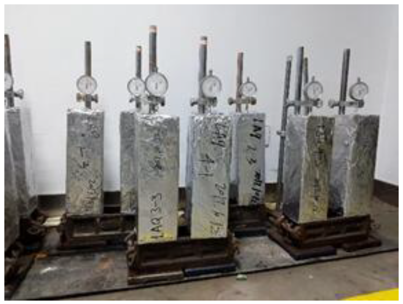
2.1. Shrinkage Performance Tests

The latest research results and engineering tracking survey results show that more than 60% of premature failure of concrete projects is caused by shrinkage cracking [24,25,26]. Once the concrete cracks, it dramatically increases its permeability. Thus, concrete shrinkage is often unavoidable, and jeopardizes the structure’s durability and safety. The shrinkage includes drying shrinkage and autogenous shrinkage. As the capillary pores of ordinary concrete contain sufficient moisture coupled with large pore size, the shrinkage tension caused by drying is not enormous, making the resulting self-shrinkage small—only about 1/10 of the dry shrinkage. Therefore, compared to the dry shrinkage of concrete, self-shrinkage is often overlooked [27]. However, the composite anti-freezing and shrinkage-reducing polycarboxylic acid water reducers were prepared for high-performance concrete in this project. The relatively low water–cement ratio and the incorporation of mineral admixtures increased the proportion of self-shrinkage in the total shrinkage, and the self-shrinkage also merits attention.

2.1.1. Drying Shrinkage

The drying shrinkage is irreversible after the concrete stops curing and loses the adsorbed water in the internal capillaries and gel pores to unsaturated air. Drying shrinkage may occur on one surface of the concrete member or all surfaces of the concrete member, and has a relatively long development process compared to autogenous shrinkage. The test was carried out using a vertical concrete shrinkage apparatus, and the prism specimen size was 100 mm in depth by 100 mm in width by 515 mm in length. Six concrete categories from Group 1 to Group 6 were selected with proportions as shown in Table 1, and three identical specimens were produced for each category. The surface of the concrete specimen was covered with film after forming during the test, and the mold was demolded after curing for two days, then put into the standard curing room for three days, and then moved to a constant temperature of 20 °C and humidity of 60% for the drying shrinkage test. After determining the specimen’s initial length, the deformation readings of the specimen were measured at intervals of 1 d, 3 d, 7 d, 14 d, 28 d, 45 d, and 60 d. The arithmetic mean of the test results of each ratio is the early shrinkage determination value of the concrete specimens of that ratio. Formula (1) calculates the drying shrinkage St:
S t = L 0 L t L b
where St is the drying shrinkage of concrete for a test period of t days, t is the time of measuring the initial length, L0 is the initial reading of the specimen length, Lt is the measured length of the specimen at test period t, and Lb is the vertical concrete shrinkage meter to measure the distance.
The drying shrinkage test results are shown in Figure 3. Concrete #4 with the maximum cement amount has the most extensive drying shrinkage, with 321.7 × 10⁻⁶ for 28 d and 345.1 × 10⁻⁶ for 60 d. The drying shrinkage value decreases with the increase in mineral admixtures such as fly ash and mineral powder when the total amount of cement material is the same. It can be explained that the addition of fly ash slows down the degree and speed of hydration of cementitious materials in the concrete [10]. Moreover, its micro-aggregate effect fills the capillary channels in cementite, blocking some of the C-H-S gel pores and compacting the internal structure of the concrete. This makes the evaporable concrete channels more curved, making it difficult for water to evaporate, reducing the dry shrinkage value of concrete under exposure to atmospheric conditions. By comparing the drying shrinkage of the six group specimens’ mix ratios, it can be seen that the composite anti-freezing and shrinkage-reducing polycarboxylic acid water reducer has a noticeable shrinkage-reducing effect. Therefore, the drying shrinkage value of the concrete used for the exterior of the bearing and pier is much lower than that of the ordinary concrete of the same strength grade.

2.1.2. Self-Drying Shrinkage

Concrete self-drying shrinkage is defined as the shrinkage deformation under sealed conditions due to the reduction in relative humidity inside the cementitious material system. Generally, the limit value of ordinary concrete shrinkage strain is only 100 × 10−6 microstrain, the impact of which can be ignored from a practical point of view. However, the influence of drying shrinkage needs to be considered. The high-strength concrete exhibits earlier, faster, and more pronounced self-drying shrinkage because of the large amount of cementitious materials and low water-to-cement ratio. These observations confirm that the drying shrinkage of high-strength concrete is much more less than the self-drying shrinkage (about 3:7). On the other hand, the self-drying shrinkage of high-strength concrete increases sharply in the initial stage and then increases slowly over time, and more than 90% of the self-drying shrinkage occurs in the first 28 days. Therefore, self-drying and drying shrinkage must be considered for high-strength concrete under dry conditions. The self-drying shrinkage test was conducted by the non-contact method in this study, and an integrated concrete shrinkage deformation tester was used to measure the concrete shrinkage deformation. The concrete surface was covered with film after forming, demolded after two days of curing, put into a standard curing room for three days, and then kept at a temperature of 20 °C and humidity of 60% for the self-drying shrinkage test. The drying shrinkage of concrete was used to evaluate the self-drying shrinkage characteristics, and the self-drying shrinkage was calculated by Formula (2):
ε s t = L 10 L 1 t + L 20 L 2 t L 0
where ε s t is the autogenous shrinkage of concrete for a test period of t days, t is the time of measuring the initial length, L10 is the initial reading of the left non-contact displacement transducer (mm), L1t is the reading of the left non-contact displacement transducer for the test period t (mm), L20 is the initial reading of the right non-contact displacement transducer (mm), L2t is the reading of the right non-contact displacement transducer for the test period t (mm), and L0 is the measurement distance of the specimen (mm), which can be defined as the specimen length minus the sum of the length between the two reflective targets buried along the specimen’s length.
Figure 4 shows the test results of self-drying shrinkage from the #1 to #6 concrete specimens. It can be seen that the self-drying shrinkage of the internal concrete of the bearing (C35) of proportion #2 and the external concrete of the bearing (C35) of proportion #3 was significantly lower than that of the regular C35 concrete of proportion #1. Similarly, the self-drying shrinkage rates of the internal pier (C40) concrete of mix ratio #5 and the external pier concrete of mix ratio #6 were also much lower than that of the ordinary C40 concrete of mix ratio #4. Moreover, the normal concrete with ratio #4 had the most considerable self-drying shrinkage, because its cement component is significant. The exothermic heat of hydration was mainly concentrated in the early stage. The total self-drying shrinkage was reduced, and slowed down the shrinkage rate of the concrete, because of the inclusion of fly ash and mineral powder at the location of the bearing and pier. Figure 4 shows that the growth rate of self-drying shrinkage was significantly reduced with the increase in fly ash and mineral powder, and the shrinkage curve becomes gentle when comparing #2 and #3 with the other mix ratios. This can be explained by the micro-aggregate effect of fly ash. The fine particles of fly ash are uniformly dispersed in the cement paste, and become the core of many hydrate deposits. These fine particles and their hydration products fill the cement pores and improve the pore structure of concrete as the hydration time progresses, reducing the concrete shrinkage. It also can be observed that specimen #3 of the C35 bearing concrete had the lowest self-drying shrinkage, with a shrinkage value of 132.1 × 10⁻⁶ for 28 d, and tended to stabilize the autogenous shrinkage value, which only increased by 8.6% at 60 d. For the C40 pier concrete, specimen #6 had the lowest self-drying shrinkage, with a shrinkage value of 169.4 × 10⁻⁶ for 28 d. Therefore, it can be concluded that the concrete structure becomes denser and effectively enhances the shrinkage resistance of concrete when using composite anti-freezing, shrinkage-reducing polycarboxylic acid water reducer and polypropylene fiber.

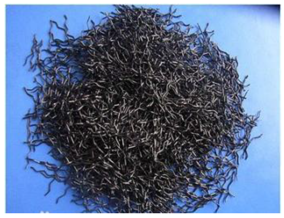
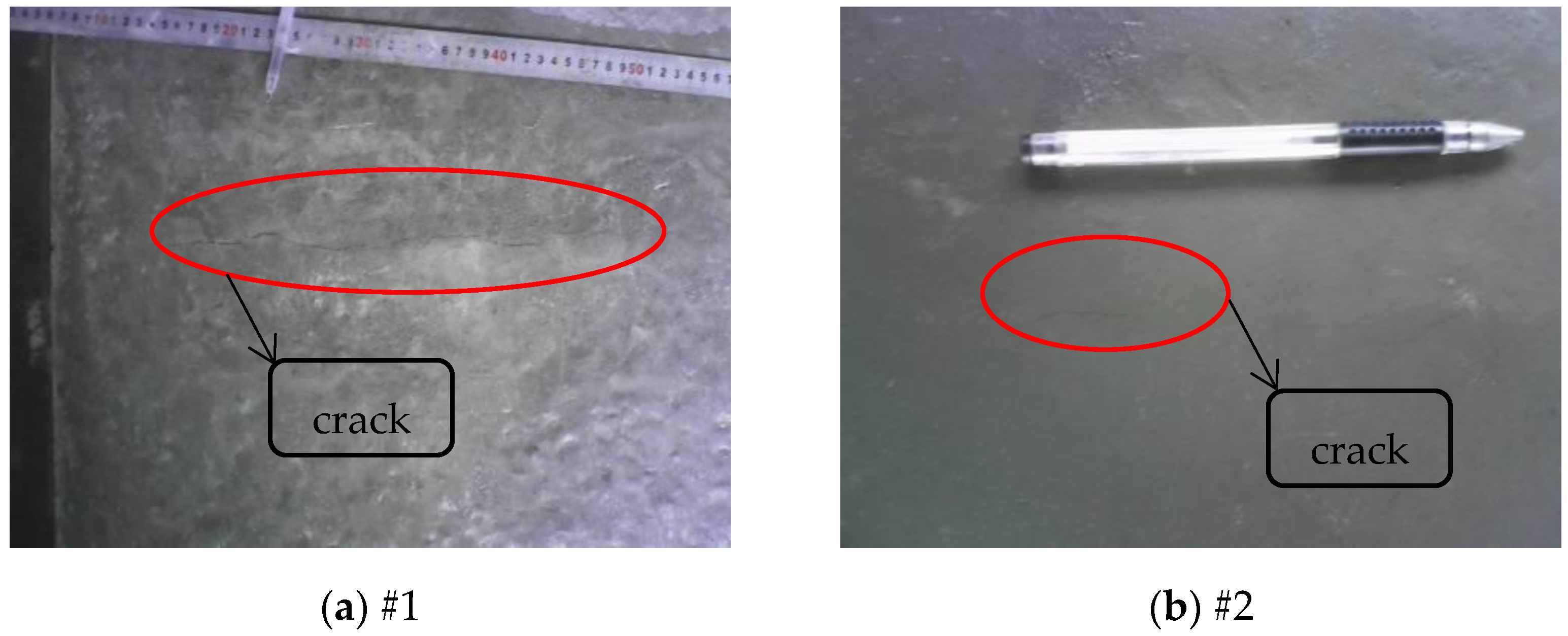
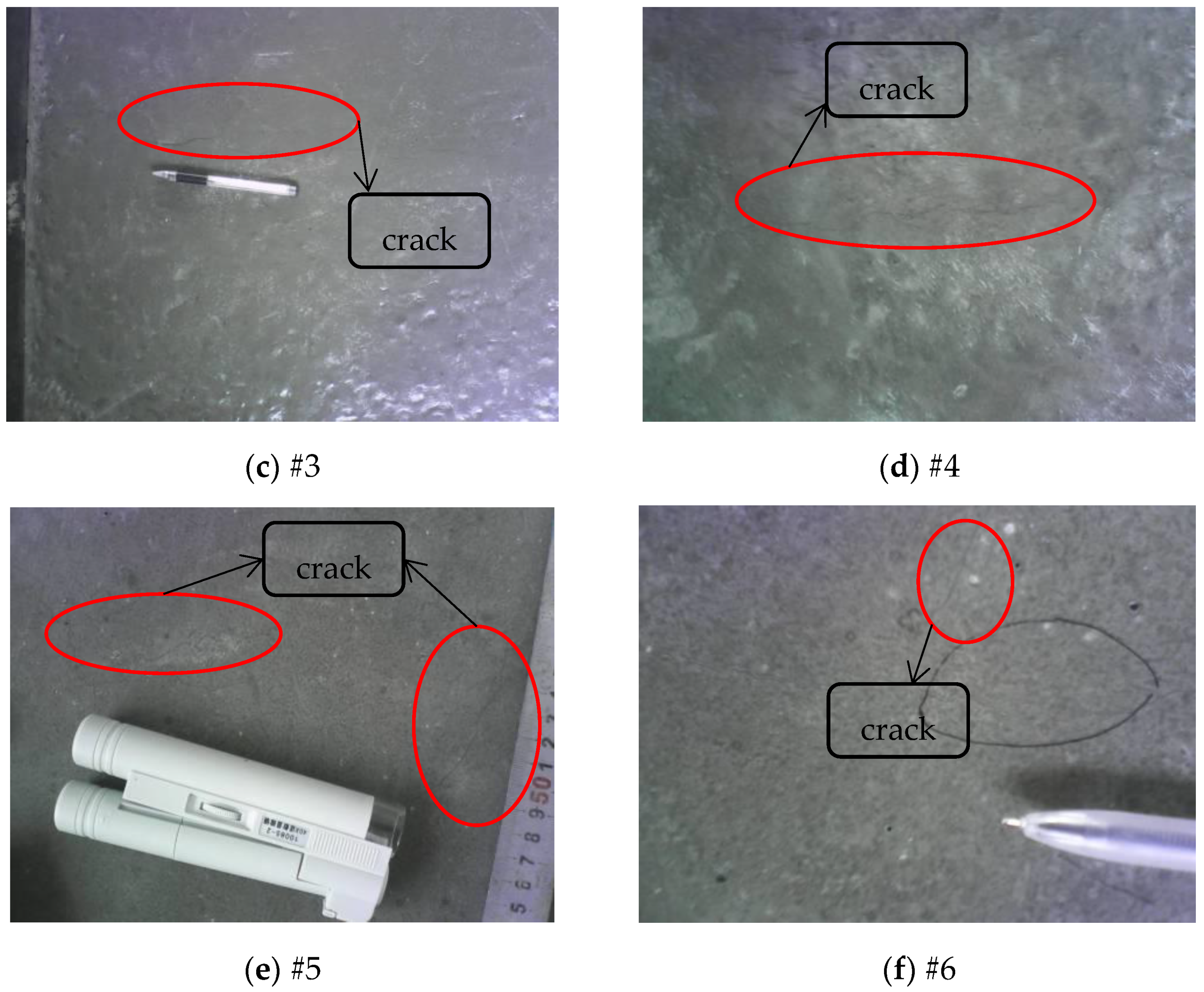
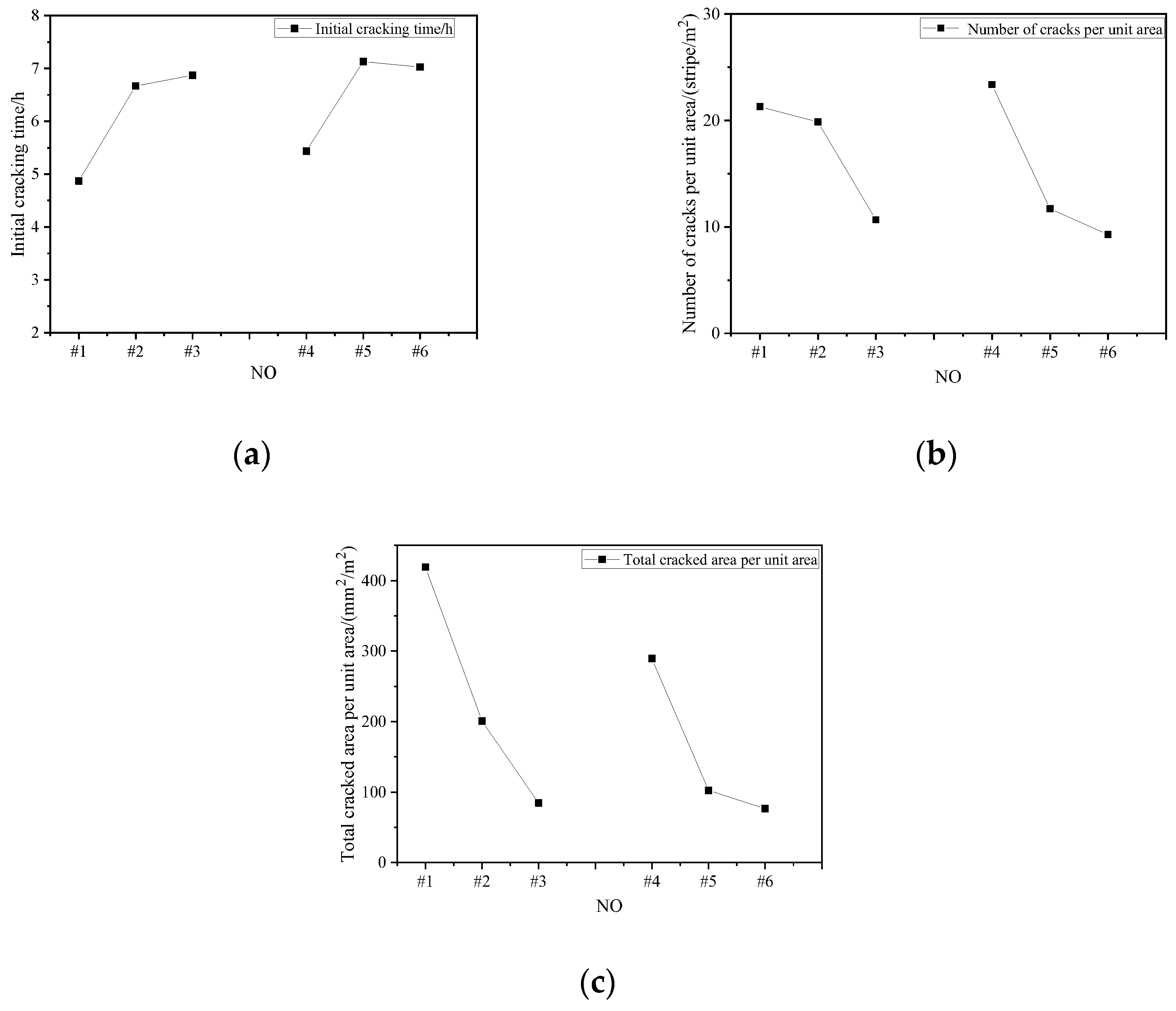
2.2. Early Crack Resistance Test

The difference between the internal and external temperature of the mass concrete and the drop in external temperature cause temperature shrinkage, and restraint is inevitable in the actual project, which inevitably leads to tensile stresses within the concrete. Moreover, the tensile strength of concrete in the early stages is generally low. Early cracking occurs when the internal tensile stress caused by shrinkage exceeds the tensile strength of concrete, and the appearance of cracks accelerates the deterioration of concrete and seriously affects the safety and durability of the structure. Therefore, it is essential to study the early cracking resistance of concrete [28]. The early crack resistance test was conducted using the flat-plate method with a test temperature of 20 °C and relative humidity of 60%, subject to 24 h crack data after pouring. The test results are shown in Table 3.
According to the evaluation method stipulated in the Concrete Durability Inspection and Evaluation Standard (JGJ/T 193-2009), it can be seen that the early crack resistance grades of concretes #2, #4, and #5 all reach level IV, as shown in Table 3. However, with excellent crack resistance performance, concretes #3 and #6 had significantly improved crack resistance due to the incorporation of imitation steel fibers, with their crack resistance grade reaching level V. On the other hand, the early crack resistance grade of the #1 specimen of ordinary concrete was Ⅲ, which is relatively poor.
Figure 5 shows the results of the concrete cracking characteristics for the six different ratio groups. As shown in Figure 5, by comparing the crack characteristics of #3 and #6 with #1, #2, #4, and #5, whether with the mix ratio of C35 or C40, the cracks of #3 and #6 with increased fibers were both few and without obvious directionality, showing excellent crack resistance. On the other hand, the average cracking area and quantity of concrete cracks in ratios #2 and #4 did not increase much, because the polypropylene imitation steel fibers incorporated in #3 and #6 have excellent crack-arresting and matrix-strengthening functions. In addition, the cracked fiber grid system forms a whole with the cement stone when microcracks occur in the cement stone structure under external forces, thus dispersing the fracture stress to other parts.
Figure 6 shows the concretes’ early cracking resistance analysis results. The different contents of fly ash and mineral powder play an essential role in the early cracking resistance of concrete in terms of the initial cracking time, as shown in Figure 6a. The initial cracking time was significantly delayed for C35 and C40 concrete mixed with higher amounts of fly ash and mineral powder. The trend of initial cracking time was similar between C35 and C40, and slightly similar between #2, #3, #5, and #6. The greater the mineral admixture content, the longer its initial cracking time, and the early cracking resistance of #2, #3, #5, and #6 is good. This is because polycarboxylic acid water reducer is an efficient surfactant, which can effectively reduce the internal capillary tension of concrete. Furthermore, the slow-setting component makes the setting time of the concrete longer. The early hydration of cement is relatively reduced, the volume reduction of the cementite is low, and the deformation ability of the concrete before setting reduces the shrinkage stress due to early shrinkage. The creep performance of this concrete shows enhanced creep ability, effectively reducing the risk of concrete cracking. Figure 6b shows the number of cracks per unit of area, and no apparent linear relationship is observed between the fly ash and mineral powder contents. The cracks are minimal and not concentrated when the content of fly ash increases (#2 > #3 > #5, #6). Although the number of cracks per unit of area is high, the length and maximum width of the cracks are smaller, so the total cracked area per unit of area is insignificant. Figure 6c shows the concrete with polypropylene imitation steel fibers. C35 and C40 concrete showed the same trend, with the smallest total cracked area using concrete mixed with polypropylene imitation steel fibers. In addition, the anti-freezing and anti-cracking mass concrete applied to the exterior of the mass concrete structure can significantly inhibit the generation of structural temperature cracks.

2.3. Impermeability Test

Concrete corrosion is mainly caused by the intrusion of water and harmful ions, and impermeability is an essential index for evaluating the durability of concrete [29]. Thus, the concrete mix design is still selected in Table 1, and the impermeability of functional gradient concrete is investigated in this study.

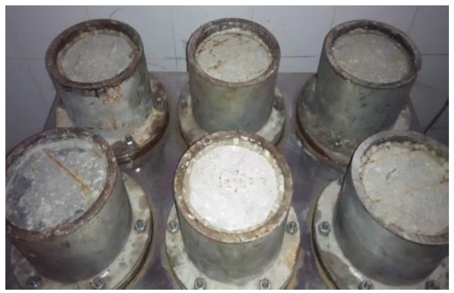
2.3.1. Water Penetration Resistance Test

The water penetration resistance test was carried out on the upper φ175 mm × lower φ185 mm × height 150 mm round test piece, using the step-by-step pressurization method. The test process is shown in Figure 7. The water pressure started from 0.1 MPa and increased by 0.1 MPa every 8 h. The specimen’s water seepage was observed during the stabilization process, and the time when the water seepage occurred was recorded. The specimen height was taken as the water seepage height. If there was no water seepage at the end of the test, the test was stopped after 24 h. No water seepage occurred in any of the specimens during the test, and the water penetration resistance results are shown in Table 4.
It can be seen that the seepage pressure of #3 and #6 reached 1.3 MPa when anti-freezing and anti-cracking mass concrete was used in this test. In addition, the impermeability grade was more remarkable than W10, representing excellent water infiltration resistance. The seepage pressure of concrete #5 for the inner pier reached 1.4 MPa, and the impermeability grade was higher than W10. All of the above water infiltration resistance values meet the requirements of bridge engineering applications. It can be explained that the mineral admixture mix achieves the densest skeletal buildup, and the micro-aggregate effect of fly ash fills its internal pores, blocking the seepage channels and enhancing the seepage resistance of the concrete.

2.3.2. Chloride Ion Penetration Resistance Test

The rapid chloride migration coefficient method (RCM) was used to test chloride ion penetration resistance. The test was carried out with a cylinder of 100 mm diameter and 50 mm height, and the test time was 56 d. The test results are shown in Table 5.
The test results show that the freeze-resistant and anti-cracking mass concretes’ 28 d chloride ion diffusion coefficients were all less than 3.0 × 10⁻¹² m2/s, of which #2 and #3 had the lowest diffusion coefficients. Compared with ordinary concrete of the same grade, the concretes with matching ratios #2, #3, #5, and #6 used in this test significantly improved the resistance to chloride ion attack, and effectively enhanced the durability of the concrete. It can be explained that the dense skeleton accumulation of mineral powder enhances the compactness of concrete, fills some of the pores, hinders the diffusion of chloride ions, and improves the impermeability of the concrete.

2.4. Freezing Resistance Test

The fast freezing method was selected for the freezing test, considering the engineering environment. Each category had 3 test specimens, and the prisms’ size was 100 mm × 100 mm × 400 mm. The standard freeze–thaw cycle was adopted, with a starting temperature of 20 °C, falling to −20 °C at a rate of 10 °C/h over 4 h, maintaining a constant temperature for 3 h, and then rising to 20 °C at a rate of 10 °C/h over 4 h, before maintaining a constant temperature for 1 h. One freeze–thaw cycle required 12 h. The fundamental transverse frequency of the specimen was measured every 25 freeze–thaw cycles. The arithmetic mean of the fundamental transverse frequencies of each category is the measured value fn, where f0 is the initial value of the fundamental transverse frequency of the specimen before the freeze–thaw test, and the relative dynamic modulus of elasticity of the specimens after n freeze–thaw cycles [30] was calculated by Formula (3):
P i = f n 2 f 0 2
The test can be terminated when one of the following three conditions occurs:
  • Considering the design requirements of the concrete freezing grade, the number of freeze–thaw cycles of specimens from #1 to #3 reaches 300 times, and the number of freeze–thaw cycles of specimens from #4 to #6 reaches 400 times;
  • The dynamic modulus of elasticity of the specimen falls below 60%;
  • The average weight loss rate of the specimens reaches 5%. Each group’s average mass loss rate is determined from the arithmetic mean of the three specimens’ mass loss test values.
The test results are shown in Table 6 and Figure 8.
Figure 8 shows the relationship between the frozen elastic modulus of concrete and the number of freeze–thaw cycles. The loss of dynamic elastic modulus was observed by changing the number of freeze–thaw cycles to judge the frost resistance of concretes of various strength levels. It can be seen that the concrete specimens of each ratio met the requirements of frost resistance. However, the dynamic elastic modulus loss of #2, #3, #5, and #6 was smaller than that of #1 and #4 under the same number of freeze–thaw cycles. Since concretes #2 and #5 include the composite anti-freezing and shrinkage-reducing polycarboxylic acid water reducer, the air-entraining component can introduce tiny, uniformly distributed pores, improving the frost resistance of each strength grade of concrete [31]. In addition, the monofilament polypropylene and imitation steel fibers incorporated in #3 and #6 improved the microporous structure to a certain extent, making the concrete denser and, thus, improving the frost resistance.

2.5. Carbonation Resistance Test

The carbonization test was carried out via the rapid carbonization method with a carbon dioxide concentration of 20%, relative humidity of 70% in the carbonation box, and a test temperature set at 20 °C. The prisms’ specimen size was 100 mm × 100 mm × 400 mm, and the test results are shown in Table 7.
Table 7 shows that the 28 d carbonation depth of C35 concrete (#1) was 6.7 mm, while that of C40 concrete (#4) was 5.7 mm, when the composite anti-freezing and shrinkage-reducing polycarboxylic acid water-reducing agent was not added. However, the 28 d carbonation depth of C35 concrete (#2) was 4.8 mm, and that of C40 concrete (#5) was 2.8 mm, when the unique admixture was used. The 28 d carbonation depth of C35 concrete (#3) was 3.5 mm, and that of C40 concrete (#6) was only 2.5 mm, after the admixture with imitation steel fiber. Therefore, the addition of the anti-freezing and shrinkage-reducing polycarboxylic acid water-reducing agent and imitation steel fiber can effectively enhance the carbonation resistance of concrete; meanwhile, the higher the amount of fly ash admixture, the greater the carbonation.

3. Conclusions

This research demonstrates the bridge engineering applicability of functional gradient concrete in cold regions. As a result, the following conclusions can be drawn:
  • The concept of differentiated design was presented between external and internal concrete abutment piers. The durability of the internal concrete of the bridge with an anti-freezing, shrinkage-reducing polycarboxylic acid water reducing-agent, and of the external concrete of the bridge with imitation steel fiber, was analyzed. It was verified by the shrinkage test, early cracking resistance test, and long-term performance studies of attributes such as anti-freezing, seepage resistance, and carbonation resistance. Furthermore, the durability performance of the formulated anti-freezing and anti-cracking mass concrete was analyzed and verified.
  • A large amount of mineral admixture concrete in the core of the casting body and micro-expansion anti-freezing concrete in the outer ring of the casting body can effectively improve the shrinkage resistance of concrete, enhancing the early cracking resistance and improving the durability of the concrete. All of the above technological methods meet the practical requirements of early strength, anti-freezing and anti-cracking, and internal reduction in the heat of hydration of mass concrete for bridges in cold regions.
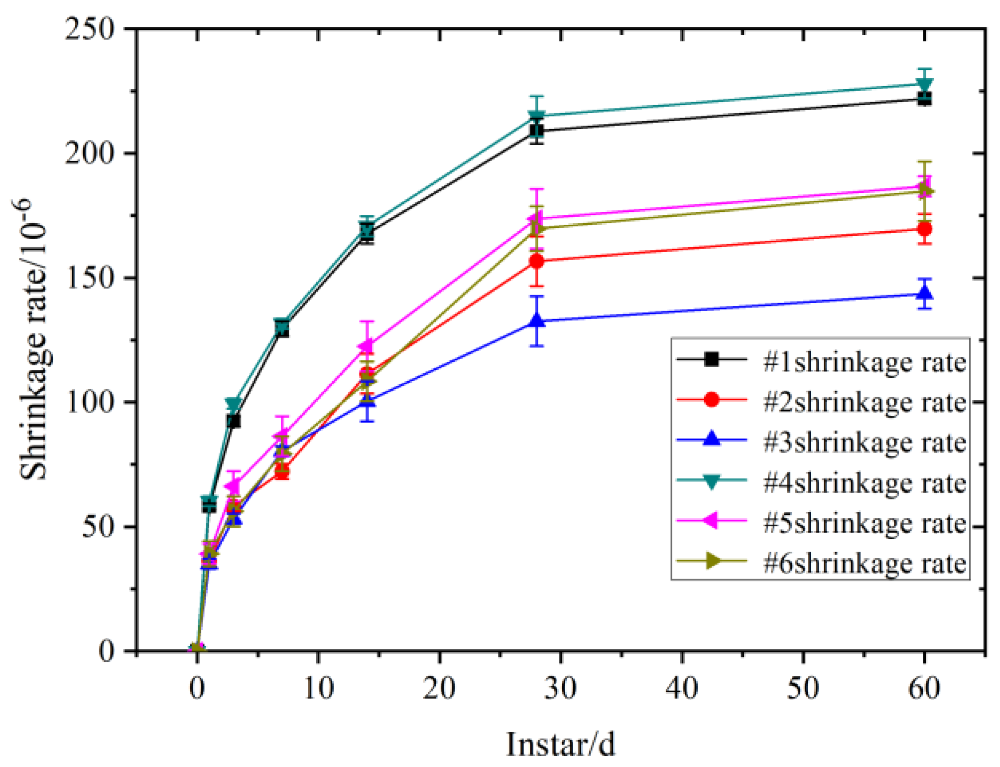
  • Ratio #4 with the maximum amount of cement had the most extensive drying shrinkage, which was 321.7 × 10⁻⁶ for 28 d and 345.1 × 10⁻⁶ for 60 d. Increasing the admixture of fly ash and mineral powder can effectively slow the concrete shrinkage rate and reduce the shrinkage value. The lowest self-drying shrinkage was found for ratio #3 of C35-bearing concrete, with a shrinkage value of 132.1 × 10⁻⁶ at 28 d. The self-drying shrinkage value only increased by 8.6% at 60 d, and then stabilized. For C40 abutment concrete, #6 had the lowest self-drying shrinkage rate, with a shrinkage value of 169.4 × 10⁻⁶ at 28 d. The drying and autogenous shrinkage rates of anti-freezing and anti-cracking concrete mixed with the anti-freezing and shrinkage-reducing polycarboxylic acid water reducer were significantly reduced. At the same time, the crack resistance grade of #3 and #6 reached grade V, which was significantly higher than that of #2, #4, and #5. The addition of steel fiber can significantly improve the crack resistance of concrete and effectively inhibit the generation and development of dry shrinkage and early cracks.
  • The 28 d chloride ion diffusion coefficient of concrete with mixture ratios #2, #3, #5, and #6 was less than 3.0 × 10⁻¹² m2/s, significantly improving the chloride ion penetration resistance ability compared with ordinary concrete of the same grade. The admixture of mineral powder can effectively increase the compactness of concrete, hinder the diffusion of chloride ions, and improve the impermeability of concrete. The admixture of anti-freezing and shrinkage-reducing polycarboxylic acid water-reducing agent can effectively improve the microporous structure, reduce the loss of dynamic elastic modulus, and improve the anti-freezing performance of concrete of all strength grades. The external anti-freezing and anti-cracking mass concrete with the anti-freezing and shrinkage-reducing polycarboxylic acid water-reducing agent and imitation steel fiber can effectively enhance the anti-carbonation performance of the concrete.
  • The mechanical properties, impermeability, fire resistance, and durability of concrete were improved due to the functional gradient structure design. However, whether functional gradient concrete can be used in underground engineering structure concrete, high-impermeability concrete, large-span structures, and high-temperature environments remains to be studied. Concrete is composed of complex multiphase materials. Using advanced preparation technologies and interface treatment technology is also the key to evaluating the performance of functionally graded concrete. Whether reinforced concrete or prestressed concrete can be completely replaced in the mass concrete structure, and whether it can be widely used in high-temperature environments, will become a hot topic in the research of concrete materials in the future.

Author Contributions

Conceptualization, S.J.; methodology, S.J.; formal analysis, S.J.; investigation, S.J.; data curation and writing—original draft preparation, S.J.; writing—review and editing, S.J. and Z.J.; supervision, W.X.; project administration, W.X. All authors have read and agreed to the published version of the manuscript.

Funding

This research was funded by Science and Technology Project of the Department of Transportation of Heilongjiang Province, grant number 2017HLJ0029.

Institutional Review Board Statement

Not applicable.

Informed Consent Statement

Not applicable.

Data Availability Statement

The data used to support the findings of this study are included within the article.

Conflicts of Interest

The authors declare no conflict of interest.

References

  1. Xingang, W.; Baoguo, M. Study of Performance and Functionally Gradient Design of Concrete Used in Underground Engineering. J. China Univ. Min. Technol. 2008, 3, 354–359. [Google Scholar]
  2. Jianzhuang, X.; Qingtian, Z.; Jiangtao, Y.; Tao, D.; Yan, L.; Jun, S. A Novel Development of Concrete Structures: Composite Concrete Structures. J. Tongji Univ. (Nat. Sci.) 2018, 46, 147–155. [Google Scholar]
  3. Yulin, Y. Review on Durability of Complex Fiber Concrete. Concrete 2012, 2, 78–80. [Google Scholar]
  4. Ming, X.; Xuezhi, W.; Huan, T. Summary of Research on Durability of Fiber Concrete. J. Liaoning Univ. Technol. (Nat. Sci. Ed.) 2020, 1, 35–39. [Google Scholar]
  5. Feng, Z.; Yin, B.; Yuebo, C.; Guijie, D.; Fengwei, N. Research Status of Low Temperature Early Strength Agents for Concrete. Mater. Rep. 2017, 31, 106–113. [Google Scholar]
  6. Lina, H.; Mengdi, H.; Wei, H.; Xuefeng, Z. Research status and prospect of mechanical properties of fiber-reinforced recycle concrete. J. Xi’an Univ. Technol. 2021, 3, 403–413. [Google Scholar]
  7. Shucheng, J.; Kai, L.; Gaozhan, Z.; Hua, S.; Qingjun, D.; Wenyuan, X. Effect of Corrosive Ions (Cl, SO42−, and Mg2+) on the Nanostructure and Chloride Binding Property of C-A-S-H Gel. J. Wuhan Univ. Technol. (Mater. Sci.) 2020, 35, 1061–1072. [Google Scholar]
  8. Jin, S.; Li, J.; Xu, W.; Ding, Q. Heterogeneous Nature of Calcium Silicate Hydrate (C-S-H) Gel: A Molecular Dynamics Study. J. Wuhan Univ. Technol. Sci. Ed. 2020, 35, 435–440. [Google Scholar] [CrossRef]
  9. Naghibdehi, M.G.; Naghipour, M.; Rabiee, M. Behaviour of functionally graded reinforced-concrete beams under cyclic loading. Gradevinar 2015, 67, 427–439. [Google Scholar]
  10. Palaniappan, S.M.; Govindasamy, V.; Jabar, A.B. Experimental investigation on flexural performance of functionally graded concrete beams using fly ash and red mud. Mater. Rio Jan. 2021, 26, 12913. [Google Scholar]
  11. Herrmann, M.; Sobek, W. Functionally graded concrete: Numerical design methods and experimental tests of mass-optimized structural components. Struct. Concr. 2017, 18, 54–66. [Google Scholar] [CrossRef]
  12. Torelli, G.; Fernandez, M.G.; Lees, J.M. Functionally graded concrete: Design objectives, production techniques and analysis methods for layered and continuously graded elements. Constr. Build. Mater. 2020, 242, 11804018. [Google Scholar] [CrossRef]
  13. Mastali, M.; Naghibdehi, M.G.; Naghipour, M.; Rabiee, S.M. Experimental assessment of functionally graded reinforced concrete (FGRC) slabs under drop weight and projectile impacts. Constr. Build. Mater. 2015, 95, 296–311. [Google Scholar] [CrossRef]
  14. Xun, W.; Wu, C.; Li, J.; Yang, C.; Li, Y. Effect of Functional Polycarboxylic Acid Superplasticizers on Mechanical and Rheological Properties of Cement Paste and Mortar. Appl. Sci. 2020, 10, 5418. [Google Scholar] [CrossRef]
  15. Wang, C.; Dong, J.; Li, D. Study on frost resistance of hybrid fiber concrete based on pore structure fractal. Silic. Bull. 2021, 40, 3608–3616. [Google Scholar]
  16. Zhang, Y. Study on Volume Stability of Limestone Powder-Slag-Fly Ash Concrete and Heat of Hydration of Composite Cementitious Materials; China University of Mining and Technology: Beijing, China, 2018. [Google Scholar]
  17. Zhao, J.; Li, X.L.; Yang, J.J. Flexural behavior of concrete with fiber gradient distribution. J. Henan Sci. 2006, 24, 100–102. [Google Scholar]
  18. Hai, R.; Yang, J.; Wu, K. Effect of glass fiber gradient distribution on mechanical Properties of cement-based Materials. N. Build. Mater. 2005, 12–14, 23. [Google Scholar]
  19. Chan, R.; Liu, X.; Galobardes, I. Parametric study of functionally graded concretes incorporating steel fibres and recycled aggregates. Constr. Build. Mater. 2020, 242, 118186. [Google Scholar] [CrossRef]
  20. Elakhras, A.A.; Seleem, M.H.; Sallam, H.E.M. Intrinsic fracture toughness of fiber reinforced and functionally graded concretes: An innovative approach. Eng. Fract. Mech. 2021, 258, 108098. [Google Scholar] [CrossRef]
  21. Lai, J.; Yin, X.; Li, H.; Zhou, J.; Kang, N. Anti-penetration explosion performance of ultra-high performance concrete based on functional gradient principle. J. Chin. Ceram. Soc. 2020, 48, 1188–1200. [Google Scholar]
  22. Roesler, J.; Bordelon, A.; Gaedicke, C.; Park, K.; Paulino, G. Fracture behavior and properties of functionally graded fiber-reinforced concrete. In AIP Conference Proceedings; American Institute of Physics: College Park, MD, USA, 2008; pp. 513–518. [Google Scholar]
  23. Gao, Y.; Ma, B.; Wang, X. Research and development of functionally graded concrete segment for shield tunnel Study on the performance of the composite composite. Chin. J. Rock Mech. Eng. 2007, 26, 2341–2347. [Google Scholar]
  24. Yang, J.; Hai, R.; Wu, K. Mechanical behavior of interfacial zone components on layered cement-based materials. J. Build. Mater. 2004, 7, 323–327. [Google Scholar]
  25. Yang, S.; Kim, H.; Lee, C.S. Investigation of shrinkage control in Ni-Al2O3 (Metal-Ceramic) functionally graded materials. Ceram. Int. 2013, 39, 93–99. [Google Scholar] [CrossRef]
  26. Wang, K.; Zhu, E.; Li, B.; Yang, W. Effect of UHPC Hydration Heat on Early Age Shrinkage Cracking of Functionally Graded Composite Beams. Bull. Chin. Ceram. Soc. 2017, 36, 38–42. [Google Scholar]
  27. Ji, Y.C.; Yail, J.K.; Jia, Y.M. Performance characterization of plain and CFRP-bonded concrete subjected to sulfuric acid. Mater. Des. 2021, 197, 109176. [Google Scholar] [CrossRef]
  28. Zhen, L. Influence of Recycled Fine Aggregates on Shrinkage of Cement Mortar and Its Mechanism. Ph.D. Thesis, Southeast University, NanJing, China, 2020. [Google Scholar]
  29. Zhijie, W.; Ziqi, W.; Ganping, Z.; Ruijin, S. Early crack resistance of composite fiber concrete. Railw. Eng. 2020, 60, 145–149. [Google Scholar]
  30. Kuan, J.; Chengzhi, Q.; Yingjie, C.; Taihang, L.; Zhenhui, L. Effects of Several Factors Such as Cellulose on the Properties of PolyethyleneFiber Reinforced Pervious Concrete. Mater. Rep. 2020, 34 (Suppl. S1), 189–192. [Google Scholar]
  31. Yang, Z.; He, R.; Tan, Y.; Chen, H.; Cao, D. Air pore structure, strength and frost resistance of air-entrained mortar with different dosage of nano-SiO2 hydrosol. Constr. Build. Mater. 2021, 308, 125096. [Google Scholar] [CrossRef]
Figure 1. Steel-like fiber.
Applsci 12 06651 g001
Figure 2. Shrinkage test.
Applsci 12 06651 g002
Figure 3. Trend of drying shrinkage with age for benchmark concretes of different strength grades and parts.
Applsci 12 06651 g003
Figure 4. Trend of self-shrinkage with age for different strength classes and parts of the base concrete.
Applsci 12 06651 g004
Figure 5. Characteristics of concrete cracks from (af).
Applsci 12 06651 g005aApplsci 12 06651 g005b
Figure 6. Comparison of early crack resistance of concrete in groups #1~#6: (a) Initial cracking time; (b) number of cracks per unit of area; (c) total cracked area per unit of area.
Applsci 12 06651 g006
Figure 7. Water penetration resistance test of concrete.
Applsci 12 06651 g007
Figure 8. Relationship between the dynamic elastic modulus of concrete and the number of freeze–thaw cycles.
Applsci 12 06651 g008
Table 1. Baseline concrete mix ratios for different strength classes and parts (kg/m3).
NumberCementFly AshMineral PowderSandGravelWaterAdditivesExternally Doped Fiber
#1250170/79210431524 general water reducers;/
#21801408076010901454 composite anti-freezing and shrinkage-reducing polycarboxylic acid water reducers/
#3210808076010901454 composite anti-freezing and shrinkage-reducing polycarboxylic acid water reducers0.75 monofilament
polypropylene fiber + 2.7 steel-like fiber + 30 expansion agent
#4290140/78010601484 general water-reducing agents;/
#5275608573210981454 composite anti-freezing and shrinkage-reducing polycarboxylic acid water reducers/
#6275608573210981454 composite anti-freezing and shrinkage-reducing polycarboxylic acid water reducers0.75 monofilament polypropylene fiber + 2.7 steel-like fiber
#1 is ordinary C35 concrete, #2 is concrete inside the bearing (C35), #3 is concrete outside the bearing (C35); #4 is ordinary C40 concrete, #5 is concrete inside the pier (C40), #6 is concrete outside the pier (C40).
Table 2. The shape and number of experimental samples.
TestDry Shrinkage TestDry Shrinkage TestFlat Plate Method TestWater Penetration Resistance TestAnti-Chlorine Ion Penetration TestFrost Resistance TestCarbonization Resistance Test
Number and shape of specimens18 prismatic specimens of 100 mm × 100 mm × 515 mm18 prismatic specimens of 100 mm × 100 mm × 515 mm12 flat-sheet specimens of 800 mm × 600 mm × 100 mm36 round-table specimens with top φ175 mm × bottom φ185 mm × high 150 mm18 specimens of φ100 mm × 50 mm high18 specimens of 100 mm × 100 mm × 400 mm18 specimens of 100 mm × 100 mm × 400 mm
Table 3. Early cracking resistance test results of benchmark concrete of different strength grades and parts.
NumberFirst Cracking Time (h)Maximum Crack Width (mm)Average Cracking Area of Cracks (mm2)Number of Cracks per Unit Area (Article/m2)Total Cracked Area per Unit Area (mm2/m2)Anti-Cracking Grade
#14.89.6118.722.3417.0III
#26.63.1610.119.8200.0IV
#36.80.187.910.784.5V
#45.49.6612.423.3288.9IV
#57.10.348.711.6100.9IV
#67.00.158.39.175.5V
Table 4. Concrete water penetration resistance test results.
Concrete Strength GradeSeepage Pressure (MPa)Impermeability GradeSeepage Pressure (MPa)Impermeability GradeSeepage Pressure (MPa)Impermeability Grade
C35#1#2#3
1.0W91.2W111.3W12
C40#4#5#6
1.1W101.4W131.3W12
Table 5. Concrete resistance to chloride ion penetration test results.
Cement Type56 d Diffusion Coefficient of Cl-/×10−12 m2/s
C35#1#2#3
4.22.52.6
C40#4#5#6
3.92.72.8
Table 6. Concrete frost resistance test results.
NumberTest ItemsNumber of Freeze–Thaw Cycles
0100200300400
#1Relative dynamic modulus of elasticity/%10093.482.361.4-
Quality loss rate/%00.71.53.4-
#2Relative dynamic modulus of elasticity/%10094.185.371.6-
Quality loss rate/%00.51.22.3-
#3Relative dynamic modulus of elasticity/%10094.586.278.6-
Quality loss rate/%00.41.12.2-
#4Relative dynamic modulus of elasticity/%10094.389.278.470.8
Quality loss rate/%00.51.32.12.9
#5Relative dynamic modulus of elasticity/%10096.290.181.676.8
Quality loss rate/%00.41.21.92.6
#6Relative dynamic modulus of elasticity/%10096.791.085.281.6
Quality loss rate/%00.41.11.72.5
Table 7. Concrete carbonation performance test results.
#1 Average Carbonation Depth (mm)#2 Average Carbonation Depth (mm)#3 Average Carbonation Depth (mm)
3 d7 d14 d28 d3 d7 d14 d28 d3 d7 d14 d28 d
3.74.86.36.72.33.24.44.82.53.33.43.5
#4 Average Carbonation Depth (mm)#5 Average Carbonation Depth (mm)#6 Average Carbonation Depth (mm)
3 d7 d14 d28 d3 d7 d14 d28 d3 d7 d14 d28 d
3.44.25.25.72.22.52.72.82.22.32.52.5
Publisher’s Note: MDPI stays neutral with regard to jurisdictional claims in published maps and institutional affiliations.

