1. Introduction
A group of mechanical power transmission systems, in which operation is based on magnetic links, enables mechanical power transmission without any physical contact between the separated parts of equipment. Examples of such devices include active or passive magnetic couplings, bearings, gears and brakes [
1,
2,
3,
4,
5,
6]. This paper aimed at a research of passive magnetic couplings, as well as devices of that group. The main purpose of a permanent magnet (PM) magnetic coupling is contactless mechanical power transfer from a driver to a follower. Additionally, a magnetic coupling is a relevant solution for overload protection. Moreover, magnetic couplings have an absence of wear due to the contactless operation principle [
7]. The operation of PM couplings is based on the interaction of permanent magnets produced from highly coercive rare-earth alloys, e.g., neodymium–iron–boron (Nd–Fe–B) or samarium–cobalt (Sm–Co) [
8]. Couplings of this type, usually, are used in isolated systems, such as systems with sealed, hermetic containers, where a motor shaft must be physically separated from a load shaft [
9]. The typical application areas of such devices include chemical, nuclear industries [
10] and medicine [
11]. Besides the traditional applications, magnetic couplings have been finding their place in novel appliances, as well as in control and robotic systems [
12,
13]. Researchers have investigated the possibility to apply magnetic couplings instead of a lever-actuated friction clutch in wind plants for mechanical power transmission from turbine shaft to a motor shaft [
14]. The advantage of a magnetic coupler to ensure motion transmission without a physical contact was also appreciated by novel product developers. Magnetic couplings were applied in a structure of an innovative design of a food and drink blender [
15]. The structure of the blender, based on power transmission by magnetic couplings, assures convenience to its user as it releases a user from a mechanical fixing operation of the blender parts.
In contrast to the active, electromagnet-based couplings, passive PM couplings themselves do not need any external power source and in an usual, synchronous mode they do not produce any noticeable heat during operation. In contrast to asynchronous eddy current magnetic couplings [
16,
17], PM synchronous couplings provide more torque per volume, better efficiency and no heat dissipation during normal, synchronous mode operation.
PM magnetic couplings are classified as an axial or radial type. In this work, we focused on axial (face-to-face)-type couplings [
18]. Axial permanent magnet couplings (APMCs) are composed of two parallel discs (two half-clutches) separated by a small layer of air or/and other non-ferromagnetic medium gap. Each of the half-clutches consist of permanent magnets glued onto ferromagnetic or non-ferromagnetic backings. Permanent magnets of the discs are magnetized in directions parallel to the axis of the couplings. The magnetization directions are opposite in the adjacent magnets of each half-clutch.
Since magnetic couplings have relevant properties for particular applications, a lot of attention has been paid to the analysis of the relationship between the mechanical characteristics and structural parameters of couplings. In [
19], authors present a technique based on analytical expressions for torque and axial force calculations. They analyzed the distribution of magnetic flux density in APMCs, presented dependencies of the force and the torque vs. angular displacement, the air-gap length between half-clutches, and the number of pole pairs. The dependence of the optimal number of pole pairs on the air-gap length is analyzed and discussed, too. In [
20], authors additionally present an analysis of APMC torque dependencies on angular and radial misalignments together with transients in APMCs. Some other aspects of magnetic couplings are covered in [
21]. There, the authors present the maximum torque dependencies on the inner and outer radii ratios of couplings, on the thickness of iron backings (yokes), as well as the dependence of the efficiency of the maximum torque per volume. The dependencies were obtained for a variety of air-gap lengths. In the mentioned related publications, the dependencies were assessed for the cases of APMCs with identical half-clutches.
The review of the works related with analysis of APMCs’ mechanical characteristics’ dependencies on their structure parameters revealed that a wide range of the aspects has been covered, but also showed some grey area for the research. One of these aspects is the influence of height difference of half-clutch magnets. It is relevant for applications where the size and weight of one half-clutch of the couplings has to be minimized. Despite the well-known influence of ferromagnetic backings on the increase of torque and axial force, a quantitative analysis of the mechanical characteristics’ dependencies on the magnetic properties of backings and an analysis for the case of couplings with different types of backings is of interest. The other relevant influencing factors which have not been covered yet are air-gap length between adjacent magnets and shape of the backings.
The main tools for research on magnetic couplings are analytical, experimental methods and numerical simulation. Researchers have suggested some analytical methods [
7,
19,
22,
23,
24,
25] for the simplified analysis. The methods have low demands on computational resources and are a valuable tool in the initial design stages. The analytical formulas were derived for particular topology of couplings with some approximations. Simplicity and low demand of computational resources of the analytical methods come with a cost of a lower precision and a lack of versatility. Therefore, finite element 3D analysis [
21] is usually applied for the cases where higher accuracy and flexibility is needed, i.e., in the design optimization stage or for research purposes. Physical experiments are valuable for a model verification but are not practical for a research of dependencies as they are time demanding and expensive. Aiming at accuracy and flexibility, the main research tool selected in this work was 3D numerical simulation. Physical experiments were applied for the numerical model verification.
This paper is organized as follows.
Section 2 describes the main research method—numerical 3D FEM simulation—applied in the work. Experimental model verification, parameters of the researched coupling and the model details are presented in
Section 3. Results of the research are presented in
Section 4. The results are summarized and discussed in
Section 5. Conclusions are drawn in
Section 6.
2. Research Methodology
The research of dependencies of the mechanical characteristics of PM magnetic couplings on their structure parameters was performed using simulations in the numerical simulation environment “Comsol Multiphysics”. The implemented FEM model (see
Figure 1) was verified by physical experiments.
In general, problems of electromagnetic analysis on a macroscopic level in “Comsol Multiphysics” is that of solving Maxwell’s equations, which are subject to certain boundary conditions [
26]
where
is the magnetic field strength,
is the current density,
is the electric displacement,
is the electric field strength, and
is the magnetic flux density.
The first equation is also referred to as Maxwell-Ampere’s law, the second one to as Faraday’s law, and the last two are respectively electric and magnetic Gauss’s laws [
26].
Constitutive relations here are used to describe macroscopic properties of the medium [
26]
where
is the permittivity of vacuum,
is the polarization,
is the magnetization,
is the permeability of vacuum, and
is the electric conductivity.
The problem could be described as magnetostatic, with no free currents in the region. For this case, Maxwell–Ampere’s law takes the simplified form [
27]
Magnetic field in this case is curl free; this means that magnetic scalar potential
exists, and magnetic field strength could be expressed as its function [
27]
Combining the magnetic form of Gauss’s law, the constitutive relations equation
and the Equation (4) gives the equation for modeling electrostatics in absence of electric currents [
27]
The numerical simulation is based on the solution of this equation.
In general case, the calculation of electromagnetic forces in “Comsol Multiphysics” involves the computation of volume forces acting on a body, and of surface forces originating from jumps in the electromagnetic fields on the boundaries. The volume and surface forces are derived from a general stress tensor that includes electromagnetic terms [
26].
Axial force
calculation in the model is based on the integration of the Maxwell’s stress tensor through a surface of the magnets positioned on one half-clutch of coupling [
26]
where
is the surface normal vector, and
is the Maxwell’s stress tensor of air.
Correspondingly, torque calculations of the coupling are based on the integral [
26]
where
r −
r0 is the vector distance from a rotation axis.
Projection of the Maxwell’s stress tensor on the outside of a solid surface is calculated according to [
26]
where
is the air pressure.
A parametric 3D model of magnetic coupling was implemented for research purposes. The parametric approach allows one to easily the change parameters of the coupling’s components without redefining its geometry. The geometry of coupling in the model was implemented using 2D “Comsol” primitives, extruding them to spatial elements.
Permanent magnets in the simulations were considered as homogeneous. Remanent magnetic flux density in the model was set as constant in a whole volume of each magnet. Directions of the remanent magnetic flux density were parallel to the rotation axis of the coupling and opposite in adjacent magnets. The magnetic insulation condition was applied for boundaries of the simulation space.
3. Model Verification
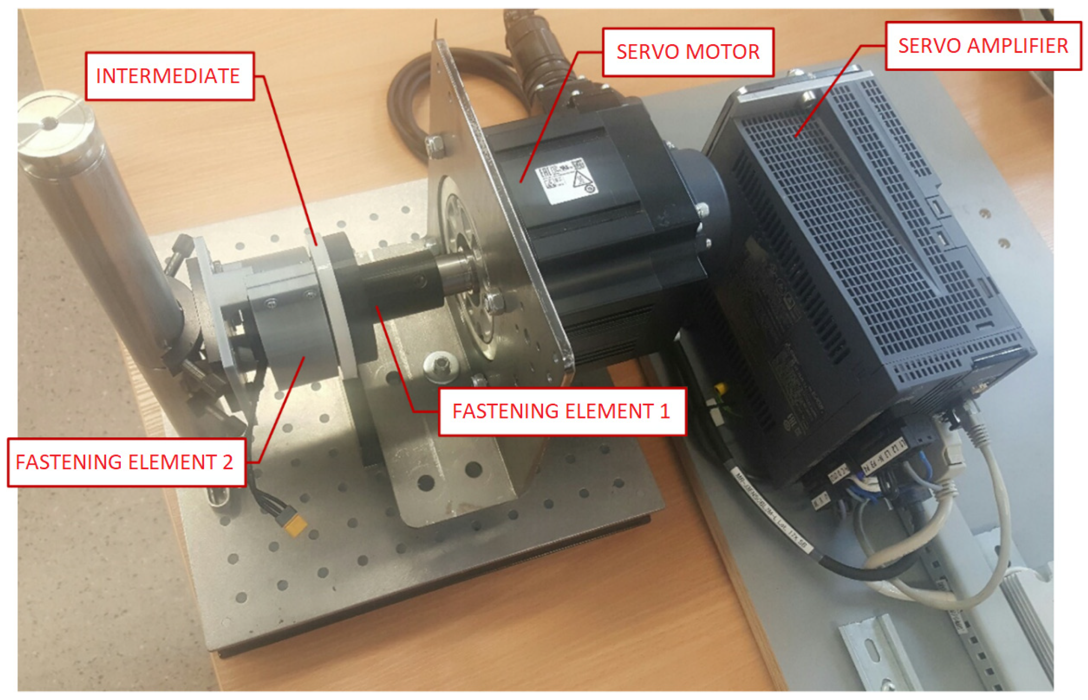
Physical experiments were performed for the numerical model verification. The experimental stand constructed for the purpose of the torque measurement is presented in
Figure 2. It consists of servo amplifier (Mitsubishi Electric MR-J4-200A-RJ), servo motor (Mitsubishi Electric HG-SR152), fastening element 1 for the first half-clutch fastening on motor axis, fastening element 2 for the second half-clutch stationary fastening, and an intermediate of 8 mm thickness for the assurance of parallel placement of the discs and for assurance of a required air-gap length. The equipment was sourced from Mitsubishi Electric (Tokyo, Japan). The servo motor is equipped with the optical encoder in the feedback loop ensuring 0.01° angle resolution. The nominal torque of the motor is 7.2 Nm and its measurement resolution is 0.072 Nm. During the experiment, one half-clutch was firmly fixed to the stationary experimental stand, the other to the shaft of the servo motor. Torque of the servo motor was gradually increased and recorded. The intermediate during the experiment was removed. The maximal torques were obtained for displacements close to 15°, which match theoretical value for clutches having 6 pole-pairs. Theoretically the maximum torque is obtained at angular displacement
, where
p denotes the number of pole pairs [
19]. This angular displacement (15°) here and, in further presented simulations, was used for the maximum torque calculations.
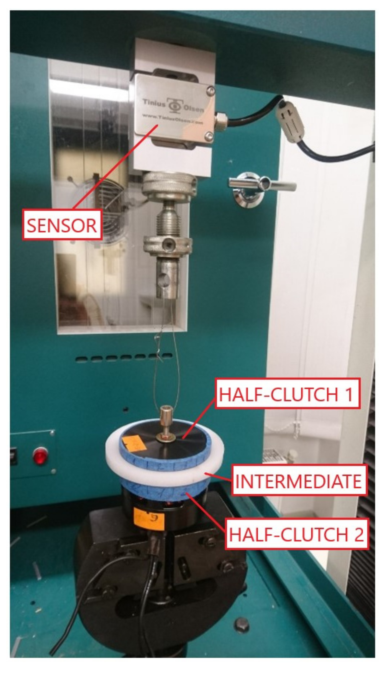
A Tinius Olsen H10KT experiment machine with a Tinius Olsen 500 N force sensor (type: DBBMTOL-500N) was used for measurements of the coupling’s axial force (see
Figure 3). The equipment was sourced from Tinius Olsen (Horsham, PA, USA). A brushless motor with a half-clutch mounted on its shaft was fixed tight. The other half-clutch was pulled by the machine by gradually increasing the force. Both half-clutches were separated by an 8 mm intermediate in the initial position. Force values causing clutch abruption were recorded. Measurements were repeated for different interacting pole pairs, followed by an assessment of averages and standard deviations. Gravitation force acting on the pulled half-clutch and on its fixing equipment was taken into consideration and excluded from the results. This way, three versions of magnetic couplings, distinguished from each other by the height of motor side half-clutch magnets, were evaluated. Theoretically, the maximum axial force is for the case of 0° degree angular displacement [
19]. Zero angular displacement is a natural position of an unloaded magnetic clutch. Zero angular displacement was used for the maximum axial force evaluation both for experimental measurements and in further simulations.
Ferromagnetic material in the close proximity to magnets affects the distribution of a magnetic field, and consequently, mechanical characteristics of a magnetic coupling. Since one half-clutch of the experimentally evaluated coupling was fixed to a brushless motor with ferromagnetic housing, it was considered in the model (see
Figure 4).
A comparison of experimental and simulation results was carried out for all three structures of the analyzed magnetic couplings. The height of the load side half-clutch magnets for all the cases was constant and equal to 3 mm. The other structure parameters of the magnetic couplings were also identical. However, the heights of the motor side half-clutch magnets were different (
Table 1). The supports of the investigated couplings are made out of non-ferromagnetic material.
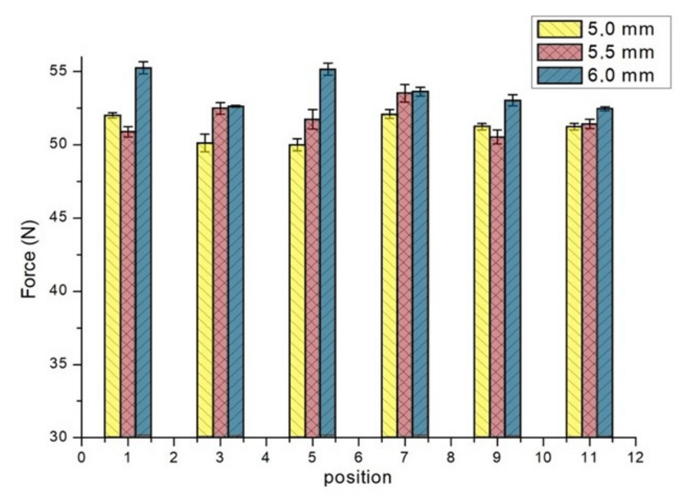
The obtained experimental (see
Figure 5) and simulation results indicate the adequacy of the numerical model (see
Table 1 and
Table 2).
The maximum torque error obtained for the case of the clutch with 5.5 mm height magnets is 1.28%, and the mean absolute error is 0.99%. The maximum axial force error, obtained also for the case of the clutch with 5.5 mm height magnets, is 4.28%, and the mean absolute error is 3.1%.
Structure parameters of the investigated coupling are listed in
Table 3, modeling environment and the model details are specified in
Table 4.
The same parameters of the clutch as listed in
Table 3 and model settings shown in
Table 4 were used in the further presented simulations.
4. Results
4.1. Influence of Height Difference of Half-Clutch Magnets
There are various research results available for couplings with both identical half-clutches. It is preferable to apply magnetic couplings with different magnets’ heights in different half-clutches for some applications. Minimization of weight or volume of one half-clutch is the criteria in some industrial designs. The example used is application of magnetic couplings in the structure of the food blender [
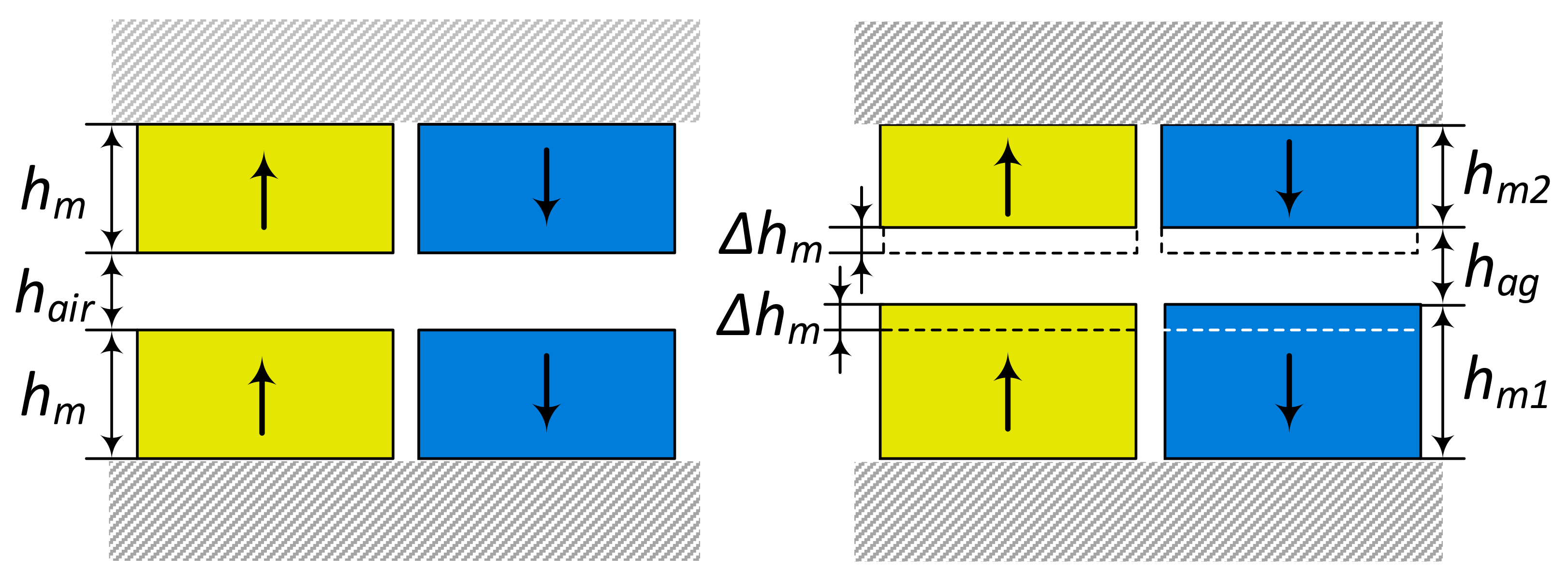
15]. Further, there are analyzed and presented dependencies of the maximum torque and the maximum axial force on the half-clutch magnets’ height difference parameter
(see
Figure 6) when the total volume of coupling’s magnets is constant.
The height of permanent magnets on different half-clutches during the simulation was set as follows (see
Figure 6)
The obtained dependencies of the maximum axial torques on magnets’ height difference parameter
for the cases of the couplings with ferromagnetic and non-ferromagnetic backings are presented in
Figure 7a,b, respectively.
The dependencies of the maximum axial force on
for the cases of the couplings with ferromagnetic backings and with non-ferromagnetic backings are presented in
Figure 8a,b, correspondingly.
The relationship of the maximum torque to is nonlinear. The sensitivity of the maximum torque to half-clutch height difference is larger in the upper range of . Dependencies of the relative maximum torque , (where is the maximum torque for the case of coupling with identical half-clutches ( = 0), and the torque for cases of coupling with non-identical half-clutches ) on are very close for the all considered air-gap values. There is a slightly higher relative torque sensitivity to for the coupling with non-ferromagnetic backings.
The dependencies of the maximum axial force, as well as dependencies of the maximum torque, on are nonlinear. Sensitivity of the maximum axial force to half-clutch height difference is larger in the upper range of .
The maximum axial force of the coupling with ferromagnetic backings indicates stronger dependence on air-gap length, especially for the cases with higher half-clutch diversity.
4.2. Influence of Backings Material
Ferromagnetic backings create conditions for easier magnetic flux circulation, i.e., implements a stronger magnetic link between half-clutches of a coupling. For particular applications, it is relevant to reduce the total weight of a system. This could be achieved by using backings made from a lighter non-ferromagnetic material. Sometimes it is relevant to minimize the weight only of one half-clutch.
To investigate the quantitative dependence of the maximum torque and the maximum axial force on material of backings, simulations were accomplished for cases of the coupling’s structures with two non-ferromagnetic material backings (
Tm0, Fm0), with one ferromagnetic backing, with one non-ferromagnetic material backing (
Tm1, Fm1), and with two ferromagnetic material backings (
Tm2, Fm2). I The considered coupling had identical half-clutches
. Other parameters of the coupling are presented in
Table 3. The results are presented in
Figure 9a,b.
The results show that the maximum torque is lower by approximately 20% for the case of the coupling with one non-ferromagnetic backing and by approximately 36% with both non-ferromagnetic backings in comparison to the case of the coupling, having both backings made from a ferromagnetic material. The dependence of the torque ratio indicates the weak dependence on air-gap length. The maximum axial force ratios indicate the higher sensitivity to the air-gap length and tend to decrease in response to increasing air-gap length.
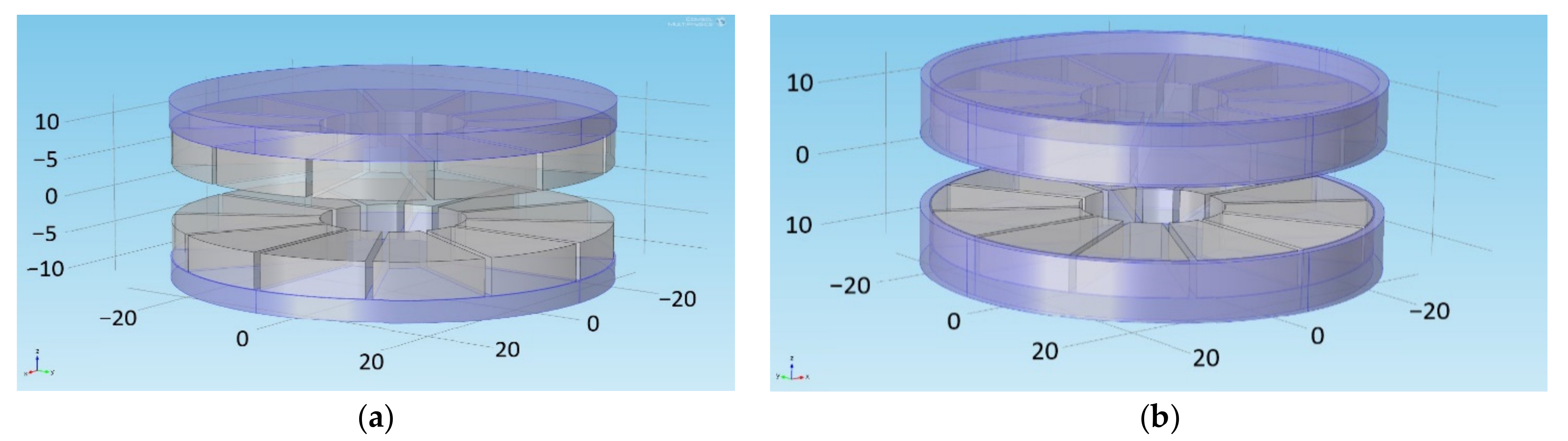
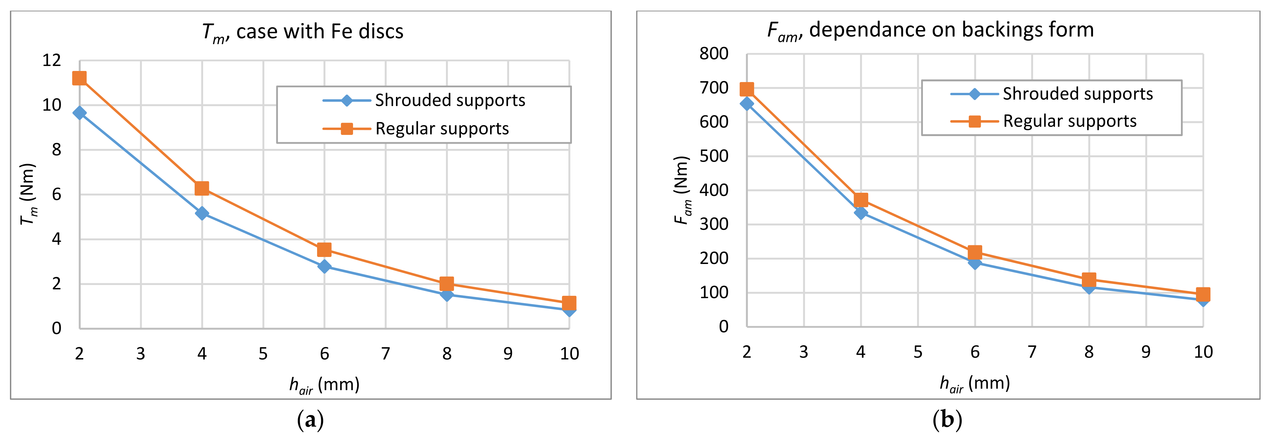
This research was performed aiming to evaluate how ferromagnetic backings with a shrouding shape (see
Figure 10b) influence the maximum torque and the maximum axial force.
The obtained results are presented in
Figure 11a,b. Ferromagnetic backings having a shrouding shape decrease both the maximum torque and the maximum axial force of the coupling. There is noticeable tendency of the ratio
reduction with increasing air-gap length. Here
denotes the maximum torque of the magnetic clutch with backings having a shrouding shape, and
denotes the maximum torque of clutch having backings of a non-shrouding shape. The influence of the shrouding effect is less significant on axial force than on torque. Similarly, the influence of shrouding effect on the maximum axial force is higher for higher lengths of the air-gap.
Since backings with a shrouding shape have significant negative effect on the maximum torque, it is not recommended to use ferromagnetic backings of this form in the structure of couplings. If shrouding is necessary, it is recommended to use backings composed from both ferromagnetic and non-ferromagnetic material parts. Parts of the backings which shroud magnets could be manufactured from non-ferromagnetic material and the parts in the region under (above) magnets out of ferromagnetic material.
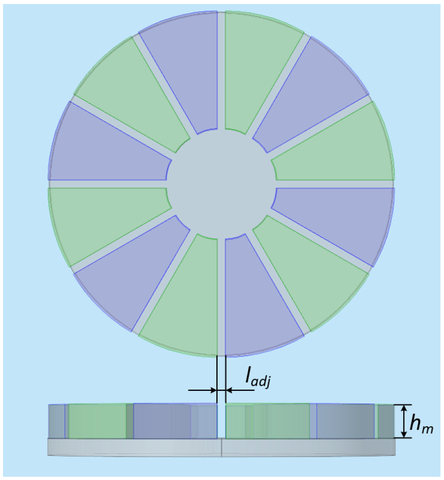
4.3. Influence of the Air-Gap Length between Adjacent Magnets
Influence of the air-gap length between adjacent magnets (see
Figure 12) on the maximum torque and the maximum axial force of the coupling was analyzed, assuming the constant volume of magnets. Identical half-clutches
were analyzed in the research.
The cross-sectional area of magnets is
where
is the air-gap length between adjacent magnets
and
. The rest of parameters were set as listed in
Table 3.
The volume of a single half-clutch magnet is
where
is height of magnets
(see
Figure 6).
To sustain the same volume of the magnets while increasing the air-gap length
between magnets, the parameter
was chosen according to the expression
The obtained results are presented in the
Table 5 and
Table 6. For the case of coupling with ferromagnetic backings, the air-gap length
has a minor influence on torque in the considered range. Torque of the coupling with non-ferromagnetic backings is more sensitive to the value of
in comparison to the case of the coupling with ferromagnetic backings. For the case, higher torque values were obtained for higher
values. The maximum axial force of the coupling is more sensitive to the air-gap length between adjacent magnets for the case of the structure with ferromagnetic backings.
5. Discussion
The research was dedicated to analyzing some of the structural aspects of axial magnetic couplings, defining their main mechanical characteristics. The influence of half-clutch geometry options, magnetic characteristics of backings material, specificity of backings form and air-gap length between adjacent magnets on the maximum torque and the maximum axial force of the coupling are covered.
Research of magnets’ height difference in different half-clutches of couplings revealed that the maximum torque and the maximum axial force values decrease in a nonlinear manner in response to the increasing difference. The sensitivity of the maximum torque and the maximum axial force to the difference is larger in the upper ranges of the difference. The results of torque ratios of the coupling with identical and with diverse half-clutches exhibit low sensitivity to air-gap length between the half-clutches, especially for a case of a coupling with ferromagnetic backings. In contrast to torque, for the case of coupling with ferromagnetic backings, the axial force exhibits a higher sensitivity to the air-gap length between half-clutches, especially in the upper range of the considered diversities.
Research of the influence of backing material on the mechanical characteristics of couplings revealed that the maximum torque is lower by approximately 20% for the case of coupling with single non-ferromagnetic backing and by approximately 36% for the case of coupling with both non-ferromagnetic backings in comparison to the case of coupling with both ferromagnetic material backings. It was determined that the maximum torque ratios of the structure with a single ferromagnetic backing or with both non-ferromagnetic backings to the torque of the structure with both ferromagnetic backings has a minor influence on air gap length. The maximum axial force ratios in comparison to the maximum torque ratios exhibit a higher sensitivity to the air-gap length and continuously decrease in response to increasing air-gap length.
Research of a backings shape’s influence on mechanical characteristics showed that ferromagnetic backings, which partially shroud magnets, decrease both the maximum torque and the maximum axial force significantly. The shrouding effect decreases the maximum axial torque by approximately 20%. The influence of the shrouding effect is less significant to axial force than to torque. As well as for torque, the influence of the shrouding effect on the maximum axial force is more significant with the increasing air-gap length.
Analysis of the influence of air-gap length between adjacent magnets showed that for the case of the coupling with ferromagnetic backings, the air-gap length has minor impact on torque in the investigated range of the air-gap length when the total volume of the magnets remained constant. The maximum torque of the coupling with non-ferromagnetic backings is more sensitive when compared to the torque of the coupling with ferromagnetic backings to the air gap length. On the contrary, the maximum axial force is more sensitive to the air-gap length for the case of the coupling with ferromagnetic backings.


 ,
, 


