Article

Construction and Application of Enterprise Knowledge Base for Product Innovation Design

1
School of Mechanical Engineering, Hebei University of Technology, Tianjin 300401, China
2
National Engineering Research Center for Technological Innovation Method and Tool, Hebei University of Technology, Tianjin 300401, China
3
Department of Mechanical Engineering, University of Manitoba, Winnipeg, MB R3T 5V6, Canada
*
Author to whom correspondence should be addressed.
Appl. Sci. 2022, 12(13), 6358; https://doi.org/10.3390/app12136358
Submission received: 18 May 2022 / Revised: 15 June 2022 / Accepted: 20 June 2022 / Published: 22 June 2022

Abstract

:
As most of the knowledge used in industrial product design is based on data files from a previous design, it is difficult to be efficiently applied in supporting product innovation design. This paper proposes a method to construct an enterprise knowledge base (EKB) for product innovation design. A concept of the functional basis of product (FBP) is first proposed based on similar products. The function units and corresponding technical units are clustered to construct an EKB for product innovation design. A retrieval path of the knowledge is then proposed from the functional level. The prototype software is developed to retrieve the knowledge directly through function units and determine the optimal technology by searching and ranking relevant patents. The patent circumvention and Theory of Inventive Problem Solving (TRIZ) methods are used to solve invention problems and obtain innovative solutions. The built EKB model provides a systematic method for the innovative product design process. An underwater separator is developed in a case study to verify the proposed method.

1. Introduction

In the increasingly competitive marketplace, product innovation is a key for enterprises to maintain their competitiveness [1,2], especially for mechanical products [3,4,5]. Due to the rapid update and iteration of mechanical products, an efficient, innovative design method is essential. Knowledge is an important source to inspire product innovation design [6,7]. An effective knowledge management system plays a very important role in the product innovation design process [8,9]. It can accelerate the formation of product design solutions and help enterprises effectively shorten the product development cycle. It can also inspire innovative ideas in the process of product design to develop innovative products.
In knowledge management, the knowledge base plays an important role in knowledge storage and management [10]. A knowledge base is a set of interrelated information and data that are stored and managed for sharing and reusing in product design [11]. The existing research mainly includes the domain knowledge base and existing enterprise knowledge management systems. The domain knowledge base is mainly constructed from the perspective of a specific product structure. For example, Mei et al. [12] presented a knowledge-base system for the composite component design to improve the design efficiency. With the development of enterprise informatization, Product Data Management (PDM) [13,14] and Product Lifecycle Management (PLM) [15] have been widely used by enterprises as knowledge management tools. They are used for the effective management of product life cycle data and processes. Many scholars have conducted research on PDM/PLM. For example, Weber et al. [16] proposed a Property-Driven Development/Design (PDD) process for product development. The concepts of a PDM/PLM system are presented based on PDD to improve the development/design activities.
These previous studies provide an important theoretical basis for the development of knowledge bases. However, the construction of these knowledge bases does not classify and store knowledge from the perspective of product innovation design. They cannot well inspire the product innovation activities for an enterprise. Because they can only store product data in a semi-structured or unstructured form, design knowledge in the enterprise cannot be reused effectively. Due to the lack of effective retrieval methods, engineers have to spend much time searching for relevant data and information in the product design. Therefore, a new knowledge base that can efficiently integrate the existing design knowledge to inspire innovative designs of enterprises is necessary. This new knowledge base is called the enterprise knowledge base (EKB) in this paper. In addition, a specific and systematic process of applying EKB for enterprise product innovation design is also required.
In order to address the above issues, based on the function-behavior-structure (FBS) model [17], this paper proposes a method to construct EKB for innovative product design. It is applied in the application process of EKB for enterprise product innovation design. In the field of engineering design [18], FBS starts from product function to form a complete mapping system from the function to behavior and then to structure, which helps engineers understand the construction process of the product. This systematic structural design thinking, which starts from the function of the target product for abstracting requirement definition to the specific structural design, can guide engineers gradually to develop products [19]. Building on the strategy literature and the research of related theories, the functional trees based on FBP are built for similar products of the enterprise. The conceptual scheme of EKB is then formed through the mapping relationship between function units and technical units. Finally, using the knowledge in the EKB and external technologies determined by patent retrieval and FOWA rankings, the process of applying EKB is developed for innovative product design. The process provides a theoretical basis for the subsequent software development and improves the efficiency of the product innovation design for an enterprise.
The remaining parts of the paper are organized as follows. Section 2 reviews the related research on mechanical product design knowledge base and functional tree. Section 3 introduces the construction of EKB based on FBP and applications of EKB in the product innovation design process. Section 4 illustrates the design process of an underwater separator to verify the feasibility and effectiveness of the proposed method. Section 5 discusses the main contributions, limitations, and suggestions for further work of this research. Section 6 concludes the whole paper.

2. Related Research

2.1. Mechanical Product Design Knowledge Base

The knowledge base was derived from artificial intelligence (AI) and a database (DB) [20]. The knowledge base realizes the scientific management of massive knowledge. It is saved in the server of a centralized storage unit to make information management convenient and can be accessed through the browser on the internet. For enterprises, a product design knowledge base is an important tool for mechanical product innovation. The existing mechanical product design knowledge base mainly includes the domain knowledge base and enterprise knowledge management system.
Research on the domain knowledge base is mainly in theoretical development and practical application. From the perspective of theoretical research, Davydenko et al. [21] proposed an ontological approach to the design of knowledge bases based on knowledge representation, which can reduce the complexity and development time of a knowledge base. Tsang et al. [22] proposed an intelligent fuzzy product design framework of a knowledge base. He et al. [23] proposed a collaborative design method for complex products based on the domain ontology knowledge base built-in cloud services. Ye et al. [24] presented an approach to design and developed a computer numerical control (CNC) machining process knowledge base using cloud technology. From the perspective of practical applications, Luo et al. [25] proposed an aircraft product model based on a knowledge base for concurrent engineering, which reduces the time and cost-to-improve efficiency of aircraft product innovation. Reddy et al. [26] built a bearing design knowledge base by integrating the commercially available CAD package SolidWorks with Microsoft Access and realized the rapid design of bearings. Dong et al. [27] proposed an intelligent design method and application of the cable route for an offshore platform by constructing an electrical database and deduction mechanism. Wang et al. [28] proposed a new method of constructing a knowledge base based on metamodeling in extension theory to guide the construction of a bearing information knowledge base. Zhang et al. [29] introduced the representation and acquisition of manufacturing composite components knowledge, database design, and algorithm design to establish a data model of composite component manufacturing knowledge based on object-oriented modeling.
PDM is one of the important approaches to knowledge management in most enterprises. PDM systems are used for gathering data from specific software, such as computer-aided design (CAD), computer-aided manufacturing (CAM), and FEM for storing and administrating data centrally [30,31]. The research topics range from the improvement of PDM systems to the integration of multi-systems and the applications of PDM. From the perspective of PDM system improvement, Ahmed et al. [32] proposed a semantic-oriented agent and knowledge base approach by introducing an intelligent semantic-oriented module on the basis of PDM systems. Li et al. [33] proposed a heterogeneous PDM system integration technology based on Web Service technology and developed an interface program to realize the data integration and interaction of heterogeneous PDM system products. From the perspective of multi-system integration, Ostroukh et al. [34] provided a complex process of the integration of PDM and ERP systems and introduced key problems in the system development. Liu et al. [35] discussed the advantages and challenges of web-based PDM systems by reviewing PDM technology. From the perspective of PDM system application, Gao et al. [36] introduced the application of PDM technologies for enterprise integration. Kropsu et al. [37] studied the practical realization of PDM and current challenges through interviews with four companies. Otto et al. [38] analyzed the means-end relationship between PDM and product data through a case study of Festo and proposed a method for evaluating and realizing the business benefits of PDM.
The concept of PLM is closely related to PDM. The common view is that PLM is the predominant concept also covering PDM activities. PLM is a strategic business approach that applies a consistent set of business solutions, which supports and integrates business processes and functions throughout the product lifecycle [39,40]. Srinivasan et al. [41] presented an integration framework for PLM to serve business and engineering needs, using open standards and service-oriented architecture. Wiesner et al. [42] identified interactions between Service Lifecycle Management (SLM) and PLM in manufacturing firms based on expert interviews and illustrated in PSS use cases. PDM/PLM systems support the information exchange between developers, especially in the later phases of the product lifecycle [43].
From the reviewed research above, the domain knowledge base realizes the storage and classification of knowledge from the perspective of a specific product structure. The traditional enterprise knowledge management systems mainly focus on the exchange of information in the product design process. Although both types of knowledge bases can store and classify knowledge from different perspectives, these knowledge bases are not constructed by classifying and storing knowledge from the perspective of product innovation design. They cannot provide effective help for innovative design. Although these knowledge bases have accumulated a lot of knowledge for enterprises, they are not reused in the innovative design process. Therefore, an EKB that efficiently integrates existing design knowledge is necessary to inspire innovative designs in enterprises. From the perspective of the innovative design of mechanical products, this paper proposes the EKB that can stimulate innovation inspiration based on function orientation. A precise product development process is proposed based on EKB.

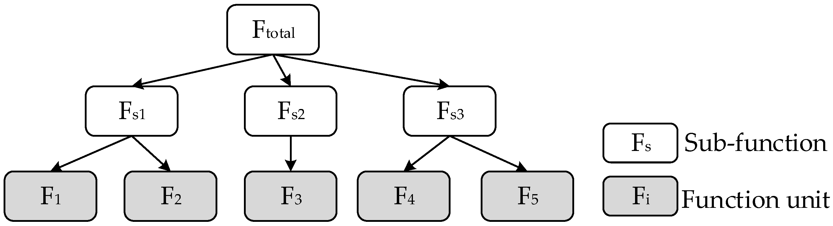
2.2. Functional Tree Research

A product is a system composed of a function and function-carrying structure [44]. Function analysis occurs throughout a product design process. An appropriate functional description and representation are key to the problem of resolution [45,46]. A functional tree [47,48] provides an abstract method for understanding and representing the relationship between the total function and sub-functions, as shown in Figure 1. The function unit [49,50] is the lowest level function in the functional tree.
In addition, the existing research solutions provide different ways to build the functional tree. Shupe et al. [51] applied the hierarchical decomposition method to obtain the functional tree of the product. Axiomatic design [52] is also an expression of hierarchical decomposition. Guo et al. [53] proposed a method to build the functional tree based on requirement analysis, which decomposes the total functions into basic and additional functions and then decomposes them into dominant and assistant functions. Based on the law of technical system integrity, Zhang et al. [54] proposed a method to build the functional tree by decomposing the total function for working, transmission, driving, and controlling.
All of the above studies adopted different strategies to develop the functional tree, but there is a lack of a unified representation of product function, which leads to ambiguous functional descriptions. Collins et al. [55] proposed 105 functions in mechanical design for the failure analysis of helicopter components. Pahl and Beitz et al. [56] listed five generally valid functions and three types of flows at a high level of abstraction. Hundal et al. [57] formulated six function classes with specific functions in each class but did not exhaustively list mechanical design functions. Lind et al. [58] divided functions into the material, energy, and action functions used in the overall design of complex industrial equipment. Altshuler et al. [59] defined 30 generic functions to specify and define the functional space of a product. Stone et al. [60,61,62,63] proposed the concept of functional basis, classified functions and flows in detail, and established a set of functions and flows with a hierarchical structure. The functional basis is a general design language for building functional trees generated. The language includes function sets and flow sets that express function units; it is widely used in mechanical and electromechanical fields. The concept of function is shown in Table 1.
The functional basis is a set of functions and flows. Functions are expressed in the form of a “verb” and are mainly divided into either a branch, channel, connect, control magnitude, convert, provide, signal, and support. Flows are represented in the form of a “noun”, including material, energy, and signal. Nowadays, the functional basis is widely accepted as a set of standardized engineering terms for the functional tree. It reduces the ambiguity of design problems at the conceptual level by using formal terms to increase the uniformity of information among functional trees. With the functional basis, Stroble et al. [64] developed an automated retrieval tool to capture the ingenuity of a design. Yoon et al. [65] proposed a function-based framework for specific technology opportunity discovery (TOD) paths. Cheong et al. [66] used functional basis classification to identify subject-action-object (SAO) triplets so as to extract functional knowledge automatically from patent texts. Liu et al. [67] developed a new function–based patent knowledge retrieval tool for conceptual product design, which enabled designers access to cross-domain patents. The NIST Design Repository Project is an ongoing project at the National Institute of Standards and Technology (NIST) that demonstrates the importance of a functional basis for the indexing and searching of information [68,69]. In addition, some Computer-aided Innovation Software (CAIS) [70,71] also combines the concept of a functional basis, such as Knowledge Gist, Ideation Workbench, and Goldfire Innovator.
However, the concept of functional basis was first introduced by Stone et al. in 2002, and it cannot be well adapted to current enterprise product design activities. Because enterprises usually produce one or several types of products, this paper proposes the concept of FBP for similar products by extending the original functional basis. On this basis, the method of building a functional tree based on FBP is presented. The FBP is then applied to the knowledge retrieval process to help enterprises efficiently reuse knowledge in the product design process.

3. Proposed Method

3.1. Construction of EKB Based on FBP

3.1.1. The Concept of FBP

Aiming at the deficiencies of the functional basis in enterprise applications, this paper proposes relevant definitions of the concept of FBP, and they are as follows: (1) FBP is a set of function units of enterprise-similar products through induction. (2) A function unit is the lowest level function determined by the technical capability of the enterprise in the process of building a functional tree. The function units are expressed in the form of a “verb + professional noun”. The “verb” is a part of the function sets of the functional basis, and the “professional noun” refers to the specific name of the product.
According to definitions (1) and (2), the FBP contains the function units of similar products of the enterprise. A complete technical system or product consists of four parts based on the law of system completeness [72]: working, transmission, driving, and controlling. The working subsystem directly performs the product function, the transmission subsystem transmits the energy to the working subsystem in the form required, the drives subsystem produces the energy required for the working of the system, and the controls system decisions of parameters and behaviors of each part change as required. Furthermore, a complete system or product includes a connection part required for the above four parts to perform auxiliary functions such as the system interaction and support, as shown in Figure 2. Therefore, the FBP can be expressed as follows.
F B P = i = 1 n F i = F W F T F D F C F A
where set F is the function unit, set FW is the working function, set FT includes the transmission function, set FD is the driving function, set FC provides the controlling function, and set FA consists of the auxiliary function for the connection and support.
To avoid repeated function units in the FBP, it is necessary to summarize and describe them in the form of “verb + professional noun”. All function units are identified by building a functional tree for all of the similar products. Then the FBP is determined by clustering all of the function units. There are often one or more products defined as similar products. Due to the different types of products, the function units determined by building a functional tree may also be different. In other words, the more types of similar products there are, the number of function units in the FBP may also increase. The FBP will continue to expand and change with the development of technology and changes in user needs. Compared with the functional basis proposed by Stone [60,61,62,63], the FBP is more specific, which is consistent with the designer’s thinking habits. At the same time, FBP provides a theoretical basis for the construction of EKB and retrieval of knowledge.

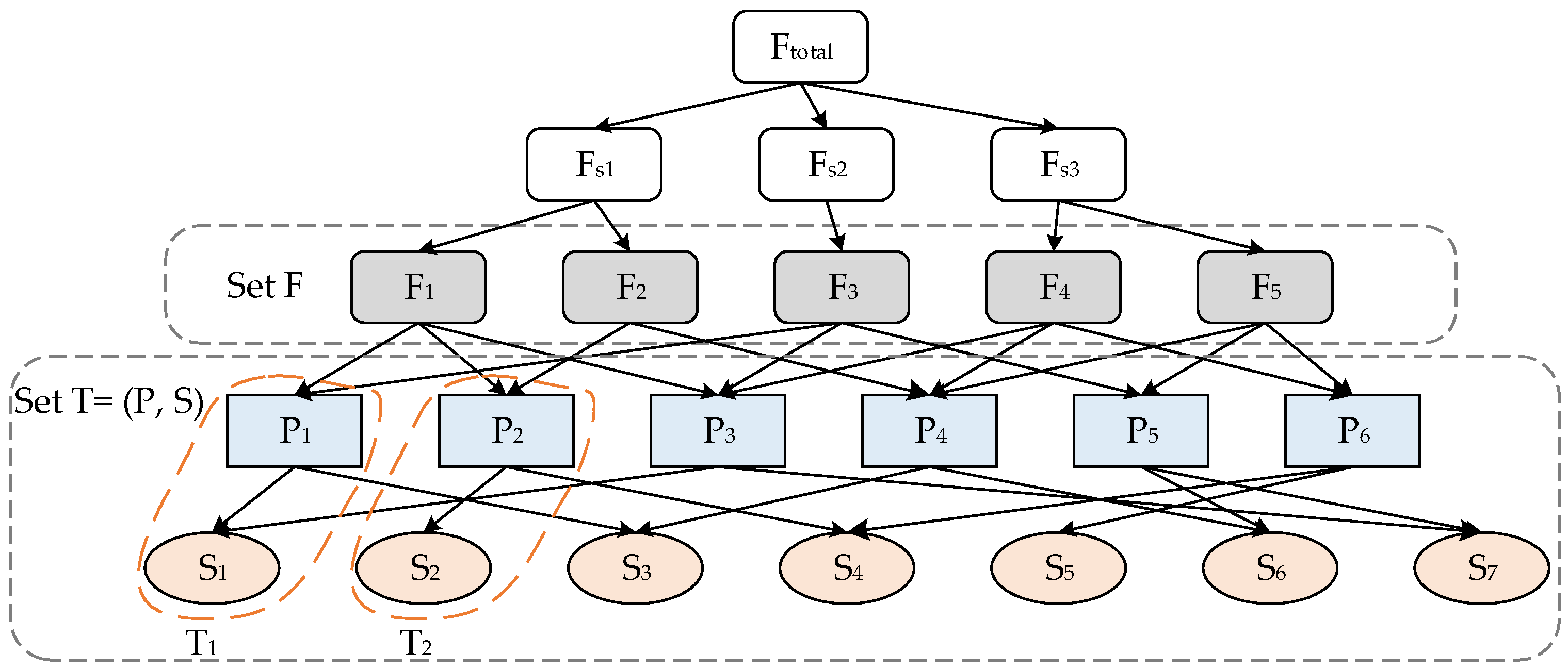
3.1.2. Technical Unit

The technical unit corresponds to the function unit, which is the principle and structure of realizing the function unit. The technical unit can be expressed as T = (P, S), where T is the technical unit, P is the principle to realize the function unit, such as a physical effect, chemical effect, or biological effect [73,74], and S is the structure that realizes the principle [75,76].
Technical units include principles and structures by definition. Here, the structure is not a general concrete structure but an abstraction of the concrete structure, which is an abstract or qualitative structure [75]. The principle is the basis for the existence of the structure; it determines how the structure realizes the function. There is a one-to-many relationship between the principles and structures, which means that a principle can be implemented by different structures. For example, the torque is transmitted by the friction effect, and the corresponding structure can be an interference fit or a clamping connection on the cylindrical working surface, as shown in Table 2.
All of the similar products are decomposed into function units, and the technical unit corresponds to them. Figure 3 shows the mapping relationship between the function units and technical units of a product. When determining the mapping relationship between the function units and technical units of similar products by summarizing and clustering, there is a many-to-many relationship between function units and technical units. In other words, the same function unit can be realized by different technical units, and the same technical unit can also realize different function units.

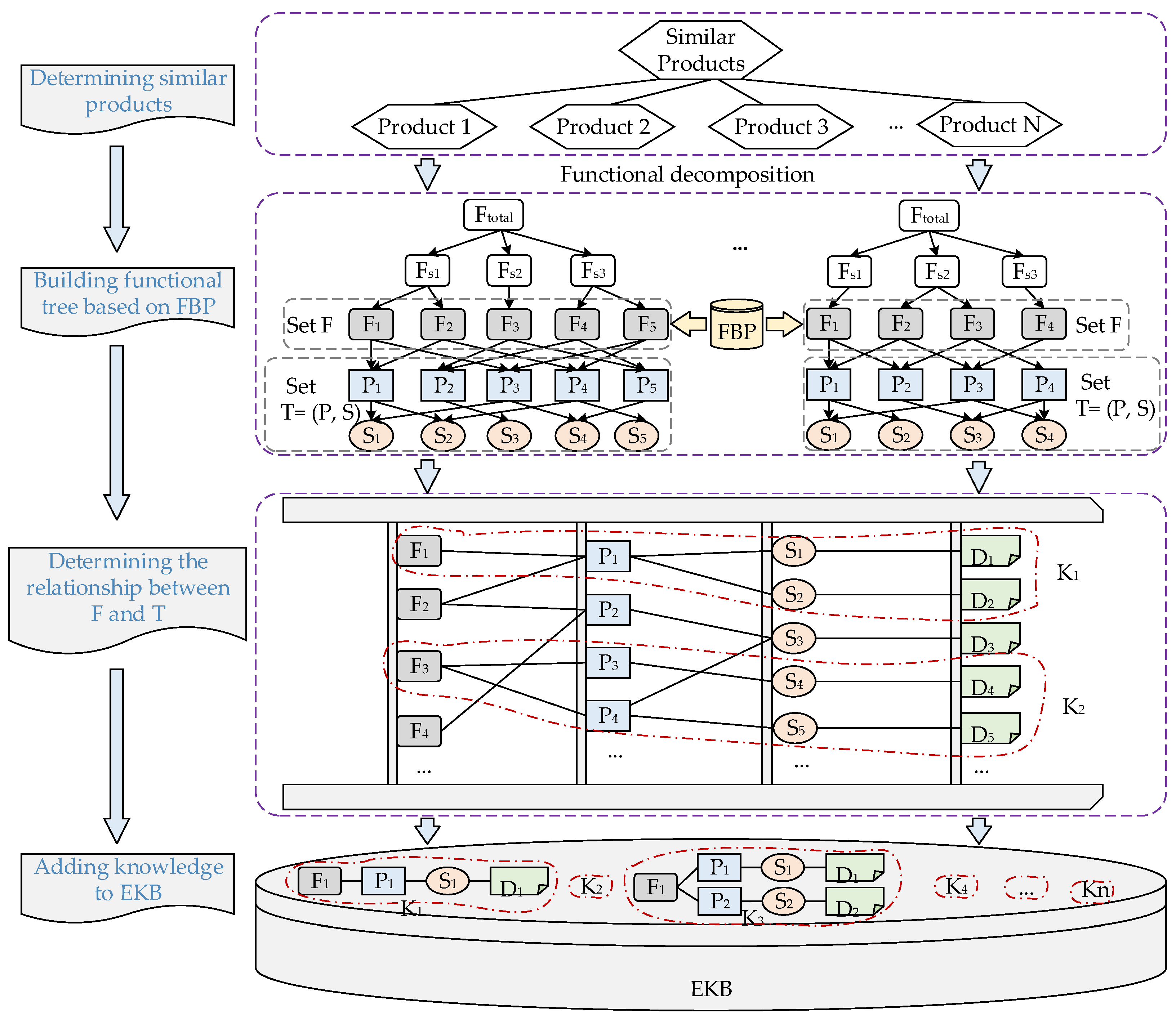
3.1.3. The Construction Process of EKB Based on FBP

This paper proposes a construction process of the EKB for similar products of the enterprise, as shown in Figure 4. The detailed steps are as follows.
Step 1: Determining similar products.
Determining similar products of the enterprise and identifying all products.
Step 2: Building a functional tree based on FBP.
All of the products are decomposed from the total function into sub-functions and function units. The function units are expressed by FBP. A functional tree based on FBP is formed to determine F = {F1, F2, ⋯, Fn} for each product and obtain the relationship between the function unit and technical unit through corresponding Tj (j = 1, 2, ⋯, m; mn).
Step 3: Determining the relationship between F and T.
According to the expression form of FBP, the FBP of similar products is determined. The mapping relationship between function units and technical units of similar products is obtained through summarizing and clustering.
Step 4: Adding knowledge to EKB.
By adding the summary results of Step 3 and relevant component drawings or assembly drawings to the EKB, the knowledge retrieved from the EKB can be expressed as follows. The red dotted line in Figure 4 represents knowledge.
  • If Fi and Tj have a one-to-one relationship, then
K = F T P , S D
2.
If Fi and Tj have a one-to-many relationship, then
K = F T 1 P 1 , S 1 D 1 T 2 P 2 , S 2 D 2 T j P j , S j D j
where K is knowledge in the EKB, F is function units in the EKB, T (P, S) is the technical units, P is the principle, S is the structure, and D includes component drawings or assembly drawings. Finally, the prototype software is developed using the Visio Studio.
Function Oriented Search (FOS) is a problem-solving tool in TRIZ theory to identify existing worldwide technologies based on function [77]. It searches for related technologies in patent databases or effect databases by generalizing the function. For the technology transfer, Montecchi et al. [78] proposed a Function/Behavior-oriented (FBOS) method to improve the patent search scope. Although these studies provide a solid foundation for the theoretical development of FOS/FBOS, they have not been well applied. We propose the EKB to efficiently integrate the existing design knowledge of the enterprise in the form of a function–principle structure. In order to help engineers obtain design knowledge with the innovation inspiration quickly, this paper constructs a knowledge retrieval path from the functional level based on the principle of FOS. The FBP is used as an index keyword to search for knowledge in the EKB. The designer selects function units expressed by the FBP in the knowledge retrieval interface and determines the technical units and drawings. In addition, the developed software can preview and download design drawings.
EKB is an important tool in the process of enterprise product innovation design, including the user layer, function layer, principle layer, structure layer, and drawing layer, as shown in Figure 5. The user layer mainly provides the login interface, which is convenient for designers to operate the EKB. The interaction between the system and designers is realized through this layer, as shown in Figure 6a. The function layer mainly provides a knowledge retrieval interface and uses the FBP as an index to guide in determining the functions to be retrieved, as shown in Figure 6b. The principle layer contains all the principles and expresses them in a unified form. The structure layer includes the structure corresponding to the principle and combines pictures and text to help designers understand. The drawing layer includes component drawings or assembly drawings. Except for the user layer, the rest of the modules provides an open environment, allowing software administrators to modify and update the knowledge in the EKB.
In order to briefly illustrate the process of using EKB software to retrieve knowledge, this paper selects the example of a nutcracker from the literature [78]. In addition, it is assumed that the relevant knowledge of the nutcracker has been added to the EKB according to the above steps. Figure 7 shows the knowledge about “open nuts” in the EKB. The knowledge of “open nuts” retrieved from the EKB based on Equation (3) can be expressed as follows.
K = F T 1 P 1 , S 1 D 1 T 1 P 2 , S 2 D 2 T 1 P 3 , S 3 D 3 T 1 P 4 , S 4 D 4 T 1 P 5 , S 5 D 5 T 1 P 6 , S 6 D 6
where F is “open nuts”, T1(P1, S1) = (gravity, hammer), T2(P2, S2) = (collision, impeller), T3(P3, S3) = (collision, separation ring), T4(P4, S4) = (extrusion, pressure plate), T5(P5, S5) = (extrusion, friction wheel), T6(P6, S6) = (centrifugation, centrifuge), and Di is the relevant drawing of Ti.
Figure 8 shows a process of retrieving knowledge using the EKB software. First, an FBP is selected to express the function unit using the function layer interface. A principle, such as “collision”, is then determined in the corresponding principle layer interface. The structures corresponding to “collision” are the impeller and separation ring. Finally, the structure “Impeller” is selected, and the drawing is reviewed.
The EKB uses the FBP as the keyword index to obtain the principle and structure. The EKB can effectively store knowledge of the product so that the existing resources and achievements of the enterprise can be reused in the product design process.

3.2. Product Innovation Design Process Based on EKB

The EKB can be used in product design and to verify the innovation of the existing design. This paper mainly studies the application of EKB in the process of product innovation design. This product design process can reduce the product development cycle, improve customer satisfaction, the success rate, and the efficiency of product design. The process of product innovation design based on the EKB is shown in Figure 9. The specific steps are as follows.
Step 1: Building functional tree of the target product based on FBP.
According to the enterprise conditions and market or user needs, a target product is determined for development. The target product is decomposed from the total function into sub-functions and function units. Function units are expressed by FBP, and a functional tree of the target product is formed. The set of the function unit is then determined as F = {F1, F2, ⋯, Fn}.
Step 2: Retrieving technical units in the EKB.
Fi (i = 1, 2, ⋯, n) is used as keywords to retrieve Tj (j = 1, 2, ⋯, m; mn) in the EKB. If the technical unit cannot be retrieved in the EKB or is unavailable, it is necessary to search outside the enterprise; otherwise, go to Step 4 to integrate all of the technical units and form an innovative solution.
Step 3: Determining technologies outside the EKB.
The relevant keywords of the function are determined to retrieve the patents in Patsanp [79]. The preliminary screening of patents is conducted based upon the IPC classification numbers and patent types. To save time in searching for the appropriate technology, the technologies are ranked. The evaluation of the technologies is a complex process that is difficult to quantify with precise numbers. This process has problems, such as subjective randomness and fuzziness. In the absence of an effective evaluation method, fuzzy numbers can be used to express expert views. Therefore, this paper introduces a fuzzy ordered weighting average (FOWA) model for the ranking process of technologies [80,81].
For example, there are four technologies, n = 4. The running indices i and j have the same domain {1, 2, ⋯, n}. The ranking process is as follows. (1) A ˜ = a ˜ i j is formed as a complementary matrix of triangular fuzzy numbers by pairwise comparisons of the four technologies. Each element a ˜ = a i j L , a i j M , a i j U in A ˜ is a triangular fuzzy number, 0 a i j L a i j M a i j U . The values of a i j L , a i j M and a i j U are selected from Table 3 to represent the experts’ ranks. (2) There are three alternative quantifier domains (a, b): maximum, at least half, and as far as possible. The corresponding values are (0.3, 0.8), (0, 0.5), and (0.5, 1), where Q is a linguistic quantifier to measure the fuzziness of the evaluation, and r is an argument. A specific value for r is determined by j/n and (j − 1)/n in Equation (10). The weighted vector w can be obtained using Equations (5) and (6). (3) Decision risk λ 0 , 1 . The smaller the value of λ , the more conservative the expert is. The expected values A ˜ λ of all elements a ˜ are searched for using Equation (7). The new matrix is named as B ˜ for a reordered A ˜ according to the expected value A ˜ λ . (4) The degree d ˜ i of each technology that is superior to other technologies can be obtained using Equation (8). The expected value D ˜ λ of D ˜ is decided using Equation (7) again, where D ˜ is a set of d ˜ i . After a normalization process, a sorting vector w , is obtained using Equation (9). The ranking results of the four technologies are determined according to w , .
w j = Q j / n Q j 1 / n
Q r = 0 , r < a r a b a , a r b 1 , r > b
a ˜ i j λ = 1 2 1 λ a i j L + a i j M + λ a i j U
d ˜ i = w 1 × b ˜ i 1 + + w n × b ˜ i n
w , = d ˜ i / i = 1 n d ˜ i
The patent infringement judgment rules are then applied to decide the preferred technology. If the infringement determination fails, it is necessary to obtain new technologies through design constraints and patent circumventions design methods [82,83]. Otherwise, the technology is directly applied as a solution for the function units.
Step 4: Searching innovative solutions.
The preliminary innovative solutions are determined by the integration of all of the technical units. The invention problems of the integration process can be solved using TRIZ tools and methods [84,85,86,87], such as 40 invention principles, separation principles, and 76 standard solutions. Finally, the EKB is updated and expanded by adding innovative solutions.

4. Case Study

Oil and natural gas are very important energy resources with great significance to economic development [88]. With the development of oil and gas production technology, the exploitation mode of oil and gas has gradually changed from the fixed platform mode to the underwater production mode. What is mined from oil wells in the deep sea is usually a mixture of oil, gas, water, and sand. When the wellhead is left at a low temperature, hydrate and emulsion will form. Therefore, an oil–water separation system must be used to separate oil, gas, water, and sand and then send them to the downstream conveying system. In this process, an underwater separator is very important. The proposed method was verified by the innovative design of the underwater separator.

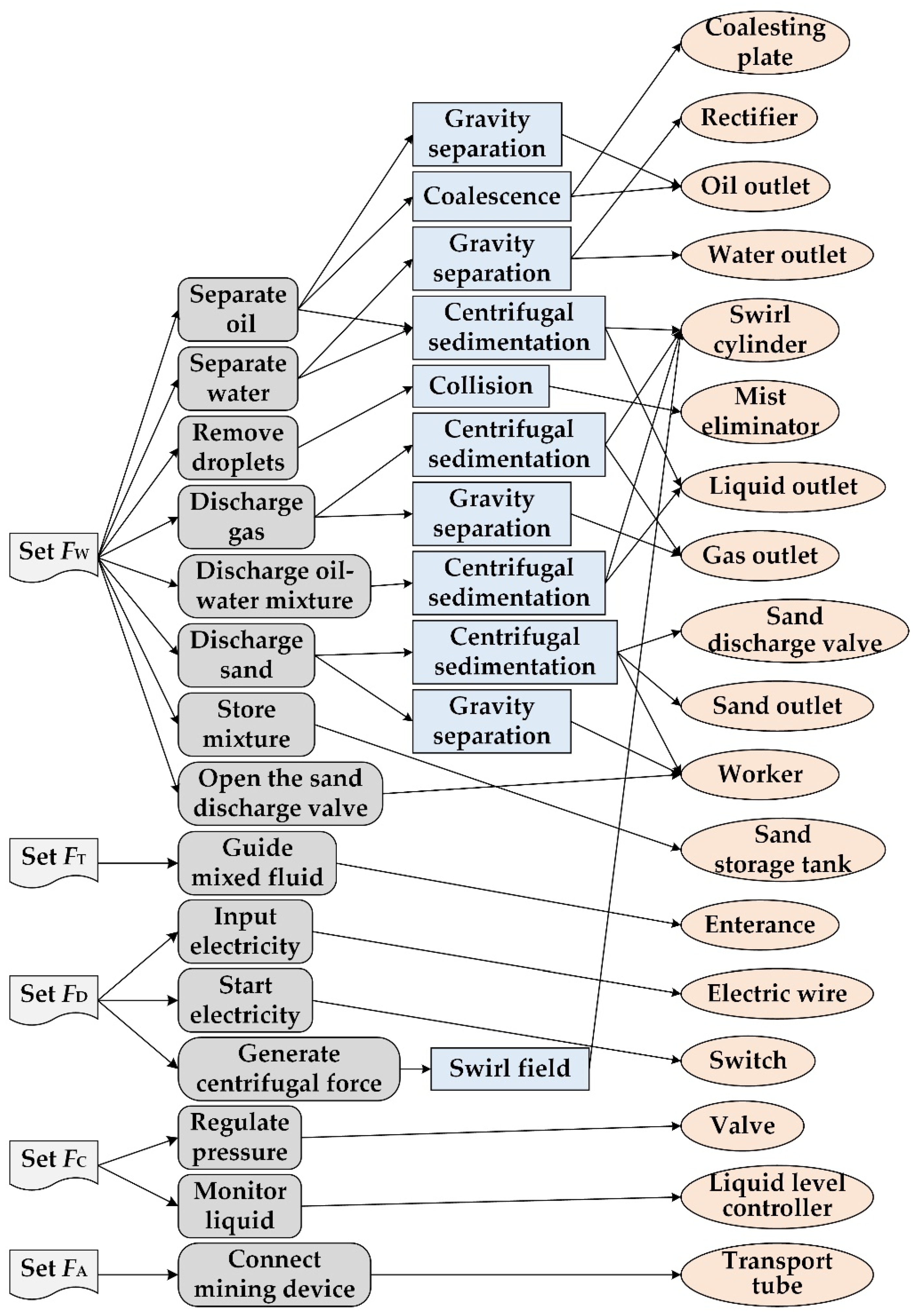
4.1. The Construction Process of EKB Based on FBP

An EKB based on FBP was built based on the design knowledge of a domestic manufacturer of underwater separators as follows:
Step 1: Determining similar products.
Underwater separators include gravity separators, centrifugal separators, and collision coalescing separators. Figure 10 and Figure 11 show the structural diagram of three similar separators.
Step 2: Building functional tree based on FBP.
Three separators were decomposed from the total function into sub-functions and function units. The function units were expressed by FBP. The functional trees were formed based on the FBP of each product, as shown in Figure 12 and Figure 13. The set of function units of each product was then determined as Fgravity, Fcentrifugal, and Fcollision. Then, the corresponding technical units were determined.
F g r a v i t y / c o l l i s i o n = x = 1 5 F W x , y = 1 1 F T y , z = 1 2 F D z , v = 1 2 F C v , k = 1 1 F A k
where FW = {remove droplets, discharge gas, separate oil, separate water, and discharge sand}, FT = {guide the mixed fluid}, FD = {input electricity, start electricity}, FC= {regulate pressure and monitor liquid}, and FA = {connect mining device}.
F c e n t r i f u g a l = x = 1 5 F W x , y = 1 1 F T y , z = 1 3 F D z , v = 1 1 F C v , k = 1 1 F A k
where FW = {discharge gas, store mixture, discharge sand, discharge oil–water mixture, and open the sand discharge valve}, FT = {guide mixed fluid}, FD = {input electricity, start electricity, and generate centrifugal force}, FC = {regulate pressure}, and FA = {connect mining device}.
Step 3: Determining the relationship between F and T.
According to the expression form of the FBP, the FBP of the separators was determined based on Equation (12). The mapping relationship between the function units and technical units of the separators was obtained through summarizing and clustering. Because the principles of some of the function units, in this case, were simple, only the corresponding structures were described, as shown in Figure 14.
F B P = i = 1 15 F i = x = 1 8 F W x , y = 1 1 F T y , z = 1 3 F D z , v = 1 2 F C v , k = 1 1 F A k
where FW = {separate oil, separate water, remove droplets, discharge gas, discharge oil–water mixture, discharge sand, storage mixture, and open the sand discharge valve}, FT = {guide mixed fluid}, FD = {input electricity, start electricity, and generate centrifugal force}, FC = {regulate pressure, monitor liquid}, and FA = {connect mining device}.
Step 4: Adding knowledge to EKB.
The summary results of Step 3 were added to the EKB. The relevant components drawings or assembly drawings were formed in the EKB. The knowledge in the EKB was reused based on Equations (2) and (3). The user interface of the EKB is shown in Figure 15 and Figure 16.

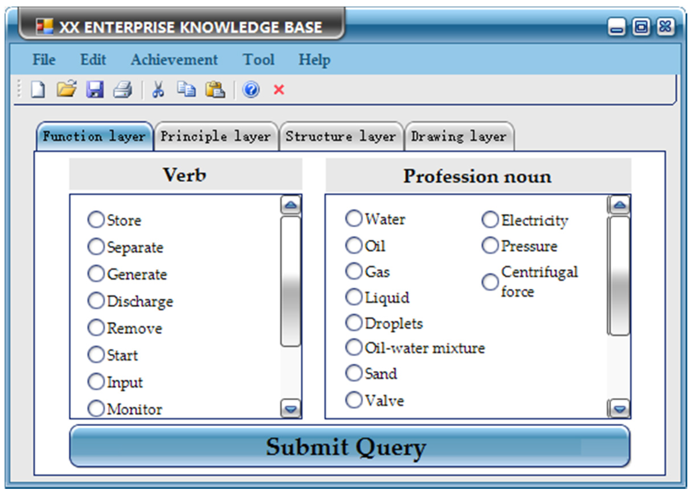
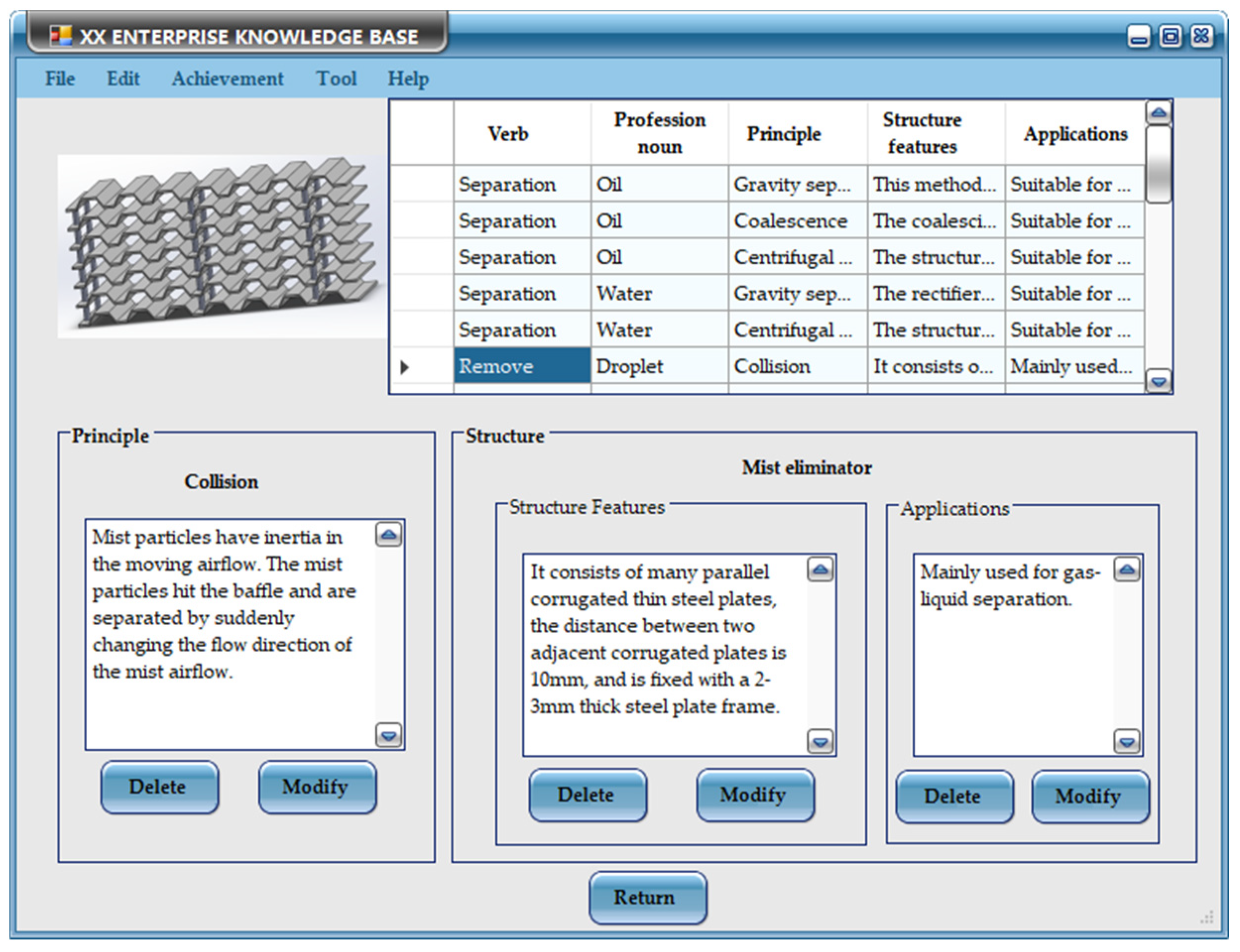
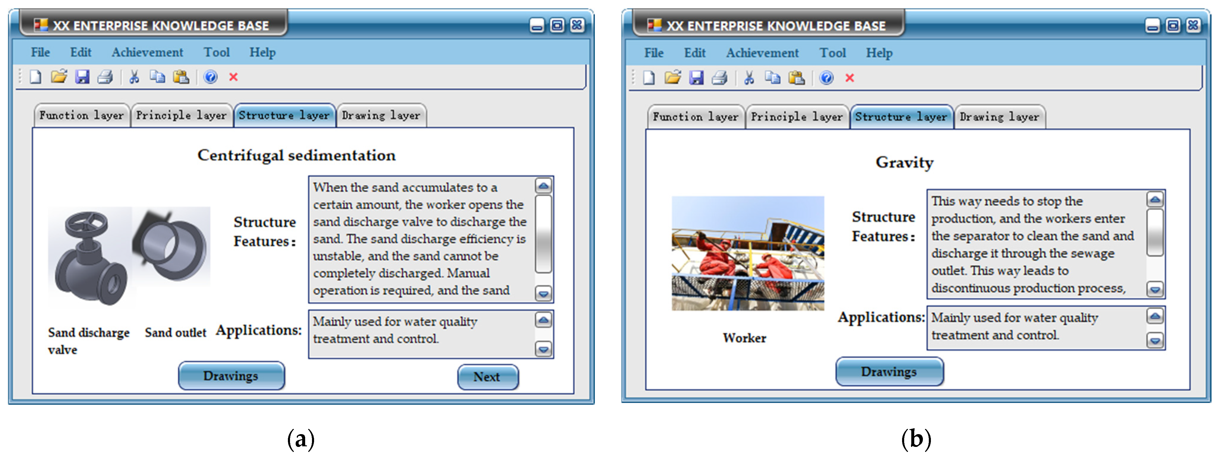
4.2. Product Innovation Design Process Based on EKB

At present, gravity separators are still dominant in actual production because of their simple structure, convenient operation, and high reliability. However, the sand-handling ability of gravity separators is an important issue in the application. After the gravity separator works for a period of time, a large amount of sand will accumulate, which will greatly affect the separation effect, and even block the equipment and cause production stoppage. Therefore, this design mainly solved the sand-discharge problem of a gravity separator. It is necessary to design an automatic sand discharge separator that can automatically discharge sand without stopping production. The steps are as follows.
Step1: Building functional tree based on of automatic sand discharge separator FBP.
The target product was determined as an automatic sand discharge separator. The required function was decomposed into sub-functions and function units to form a functional tree, as shown in Figure 17. The set of the function unit was then determined as Fautomatic.
F a u t o m a t i c = x = 1 5 F W x , y = 1 1 F T y , z = 1 2 F D z , v = 1 2 F C v , k = 1 1 F A k
where FW = {remove droplets, discharge gas, separate oil, separate water, and discharge sand}, FT = {guide mixed fluid}, FD = {input electricity and start electricity}, FC = {regulate pressure and monitor liquid}, and FA = {connect mining device}.
Step 2: Retrieving technical units in the EKB.
Fi (i = 1, 2, ⋯, 11) were used as keywords to retrieve Tj in the EKB. It was found that all Fi except “discharge sand” could find the available Tj in the EKB. Figure 18 shows the retrieve results for “discharge sand”. At present, both methods of sand discharge need manual work, which has an unstable efficiency and cannot be used to discharge sand automatically. Therefore, it is necessary to search outside of the enterprise.
Step 3: Determining technologies outside the EKB.
The relevant keywords of “discharge sand” were determined to build a formula to retrieve patents in Patsanp. The technologies were identified by a preliminary screening of patents based upon IPC classification numbers and patent types, as shown in Table 4. The FOWA method was used to rank five technologies (n = 5). The triangular fuzzy array required in the ranking process was a result provided by the three designers who have more than three years of design experience, (a, b) = (0.3, 0.8) in this case. A ˜ = a ˜ i j 5 × 5 was formed as a complementary matrix of triangular fuzzy numbers by the pairwise comparisons of five technologies. The weighted vector w = (0, 0.2, 0.4, 0.4, 0)T was obtained using Equations (5) and (6). The decision risk λ = 0.5 was set to obtain the expected value A ˜ 0.5 according to Equation (7). A sorting vector w′ = (0.138, 0.204, 0.244, 0.292, 0.123)T was obtained using a normalization process. The ranking results of the five technologies were No.4, No.3, No.2, No.1, and No.5, respectively.
A ˜ = ( a ˜ i j ) = ( 0.5 , 0.5 , 0.5 ) ( 0.2 , 0.3 , 0.4 ) ( 0.1 , 0.2 , 0.3 ) ( 0.1 , 0.3 , 0.4 ) ( 0.5 , 0.7 , 0.8 ) ( 0.5 , 0.6 , 0.7 ) ( 0.5 , 0.5 , 0.5 ) ( 0.3 , 0.4 , 0.6 ) ( 0.2 , 0.3 , 0.4 ) ( 0.6 , 0.8 , 0.9 ) ( 0.6 , 0.8 , 0.9 ) ( 0.5 , 0.6 , 0.7 ) ( 0.5 , 0.5 , 0.5 ) ( 0.1 , 0.2 , 0.3 ) ( 0.6 , 0.7 , 0.9 ) ( 0.7 , 0.8 , 0.9 ) ( 0.6 , 0.7 , 0.8 ) ( 0.5 , 0.7 , 0.8 ) ( 0.5 , 0.5 , 0.5 ) ( 0.5 , 0.8 , 0.9 ) ( 0.2 , 0.3 , 0.5 ) ( 0.2 , 0.3 , 0.4 ) ( 0.1 , 0.3 , 0.4 ) ( 0.1 , 0.2 , 0.3 ) ( 0.5 , 0.5 , 0.5 )
A ˜ ( 0.5 ) = a ˜ 11 ( 0.5 ) = 0.500 a ˜ 12 ( 0.5 ) = 0.300 a ˜ 13 ( 0.5 ) = 0.200 a ˜ 14 ( 0.5 ) = 0.275 a ˜ 15 ( 0.5 ) = 0.675 a ˜ 21 ( 0.5 ) = 0.600 a ˜ 22 ( 0.5 ) = 0.500 a ˜ 23 ( 0.5 ) = 0.425 a ˜ 24 ( 0.5 ) = 0.300 a ˜ 25 ( 0.5 ) = 0.775 a ˜ 31 ( 0.5 ) = 0.775 a ˜ 32 ( 0.5 ) = 0.600 a ˜ 33 ( 0.5 ) = 0.500 a ˜ 34 ( 0.5 ) = 0.200 a ˜ 35 ( 0.5 ) = 0.725 a ˜ 41 ( 0.5 ) = 0.800 a ˜ 42 ( 0.5 ) = 0.700 a ˜ 43 ( 0.5 ) = 0.675 a ˜ 44 ( 0.5 ) = 0.500 a ˜ 45 ( 0.5 ) = 0.750 a ˜ 51 ( 0.5 ) = 0.325 a ˜ 52 ( 0.5 ) = 0.300 a ˜ 53 ( 0.5 ) = 0.275 a ˜ 54 ( 0.5 ) = 0.200 a ˜ 55 ( 0.5 ) = 0.500
B ˜ = ( b ˜ i j ) = ( 0.5 , 0.7 , 0.8 ) ( 0.5 , 0.5 , 0.5 ) ( 0.2 , 0.3 , 0.4 ) ( 0.1 , 0.3 , 0.4 ) ( 0.1 , 0.2 , 0.3 ) ( 0.6 , 0.8 , 0.9 ) ( 0.5 , 0.6 , 0.7 ) ( 0.5 , 0.5 , 0.5 ) ( 0.3 , 0.4 , 0.6 ) ( 0.2 , 0.3 , 0.4 ) ( 0.6 , 0.8 , 0.9 ) ( 0.6 , 0.7 , 0.9 ) ( 0.5 , 0.6 , 0.7 ) ( 0.5 , 0.5 , 0.5 ) ( 0.1 , 0.2 , 0.3 ) ( 0.7 , 0.8 , 0.9 ) ( 0.5 , 0.8 , 0.9 ) ( 0.6 , 0.7 , 0.8 ) ( 0.5 , 0.7 , 0.8 ) ( 0.5 , 0.5 , 0.5 ) ( 0.5 , 0.5 , 0.5 ) ( 0.2 , 0.3 , 0.5 ) ( 0.2 , 0.3 , 0.4 ) ( 0.1 , 0.3 , 0.3 ) ( 0.1 , 0.2 , 0.3 )
D ˜ = d ˜ i 5 × 1 = 0.22 , 0.34 , 0.42 0.42 , 0.48 , 0.58 0.52 , 0.58 , 0.66 0.54 , 0.72 , 0.82 0.16 , 0.30 , 0.42
D ˜ 0.5 = 0.330 , 0.490 , 0.585 , 0.700 , 0.295 T
The application of the No.4 technology was a suction device. The sand discharge device obtained by applying the patent circumvention method is shown in Figure 19, which includes a negative pressure chamber, sand suction tube, venturi tube, sand discharge tube, and sand suction tube. The sand in the separator is sucked out through the internal and external pressure difference of the separator and discharged from the sand discharge tube.
Step 4: Searching innovative solutions.
The innovative preliminary solution of the automatic sand discharge separator was determined through the integration of all of the technical units. The separator adopts a horizontal shell structure and is provided with an inlet baffle, rectifier, and coalescing plate in sequence. There is at least one sand hopper rounded at the bottom of the shell, which enables sand to fall easily. The mixed fluid of oil, gas, water, and sand enters the separator for preliminary separation. The gas separates the droplets through a rectifier and gravity. The liquid separates the air bubbles, oil, and water through a rectifier and coalescing plates. The sand falls into the sand hopper at the bottom of the separator through a rectifier by gravity. The gas is discharged from the gas outlet after removing the droplets by the mist eliminator. The oil is discharged from the oil outlet through the weir plate. The water is discharged from the water outlet, and the sand in the sand hopper is discharged from the sand discharge device.
The sand discharge device mainly relies on the internal and external pressure difference of the separator to discharge the sand. However, when the pressure difference is insufficient, the sand discharge tube will be blocked, and the sand cannot be effectively discharged. According to TRIZ Standard Solution No. 3 (1.1.3), if the system cannot be changed, but permanent or temporary external additive changes S1 or S2 are acceptable, the solution is obtained. A nozzle connected to the high-pressure water pump is installed, and the negative pressure formed by the high-pressure water is used to discharge the sand, as shown in Figure 20. In addition, in the process of resource analysis, it was found that the continuous input of high-pressure water wastes resources. According to the principle of time separation, a flow sensor is installed on the inner wall of the sand discharge tube to monitor the sand flow. When the sand accumulates to a certain value, a control signal is sent to the controller, which controls the valve of the high-pressure water pump to open. The sand in the separator is then discharged.
Therefore, the sand discharge device has two ways to discharge sand, as shown in Figure 21. One is to rely on the internal and external pressure difference of the separator to discharge sand, and high-pressure water is not required at this time. The other is to monitor the sand flow through a flow sensor. When the sand discharge tube is blocked, the sand flow will be reduced. Furthermore, when the flow sensor determines that the sand flow reaches the preset upper limit, it transmits a control signal to the controller to control the valve of the high-pressure water pump to open. The negative pressure formed by the high-pressure water is used in the negative pressure chamber to discharge the sand. After a period of sand discharge, the signal received by the flow sensor will weaken. The valve of the high-pressure water pump is closed through the preset lower limit value of the controller, and the first mode is started at this time.
The structure of the automatic sand discharge separator is shown in Figure 22, which has good sand settling and discharge effects. It can automatically discharge sand without production, which prolongs the maintenance cycle of the separator and has high practical value. Therefore, the automatic sand discharge separator is already in production. Finally, according to the expression of knowledge, the sand discharge device was added to the enterprise knowledge base, as shown in Figure 23.

5. Discussions

5.1. Implications

This paper contributes to the construction of an EKB for innovative product design and the application process of EKB in enterprise product innovation design. The construction method for the EKB presented in this paper provides a new model for enterprise knowledge management and theoretical support for subsequent software development. In addition, the product innovation design process based on the EKB proposed in the paper provides a systematic method for enterprises to develop new products, which can effectively shorten the product development cycle. The main contributions of this research include the following three aspects:
(1)
The construction of an EKB is a prerequisite for knowledge reuse in an enterprise. The construction process of existing knowledge bases does not consider the classification and storage of knowledge from the perspective of product innovation; they cannot provide innovative knowledge for product innovation design. Although these knowledge bases have accumulated a lot of knowledge for enterprises, they have not been reused in the innovative design process. Some CAIS can provide innovative knowledge for the product design process, such as the Goldfire innovator, Ideation Workbench. However, they can only provide technical solutions outside the enterprise and cannot effectively manage previous design achievements. From the perspective of the functional design of product innovation, this paper proposes an EKB that efficiently integrates existing design knowledge to inspire the product innovation design of an enterprise. The EKB stores product information in the form of K = {Fi Ti (P, S) Di}, which can maximize the reuse of previous achievements and provide rich, innovative knowledge to help engineers generate innovative ideas in the product design process. The EKB improves upon the limitations of a traditional knowledge base for product innovation design.
(2)
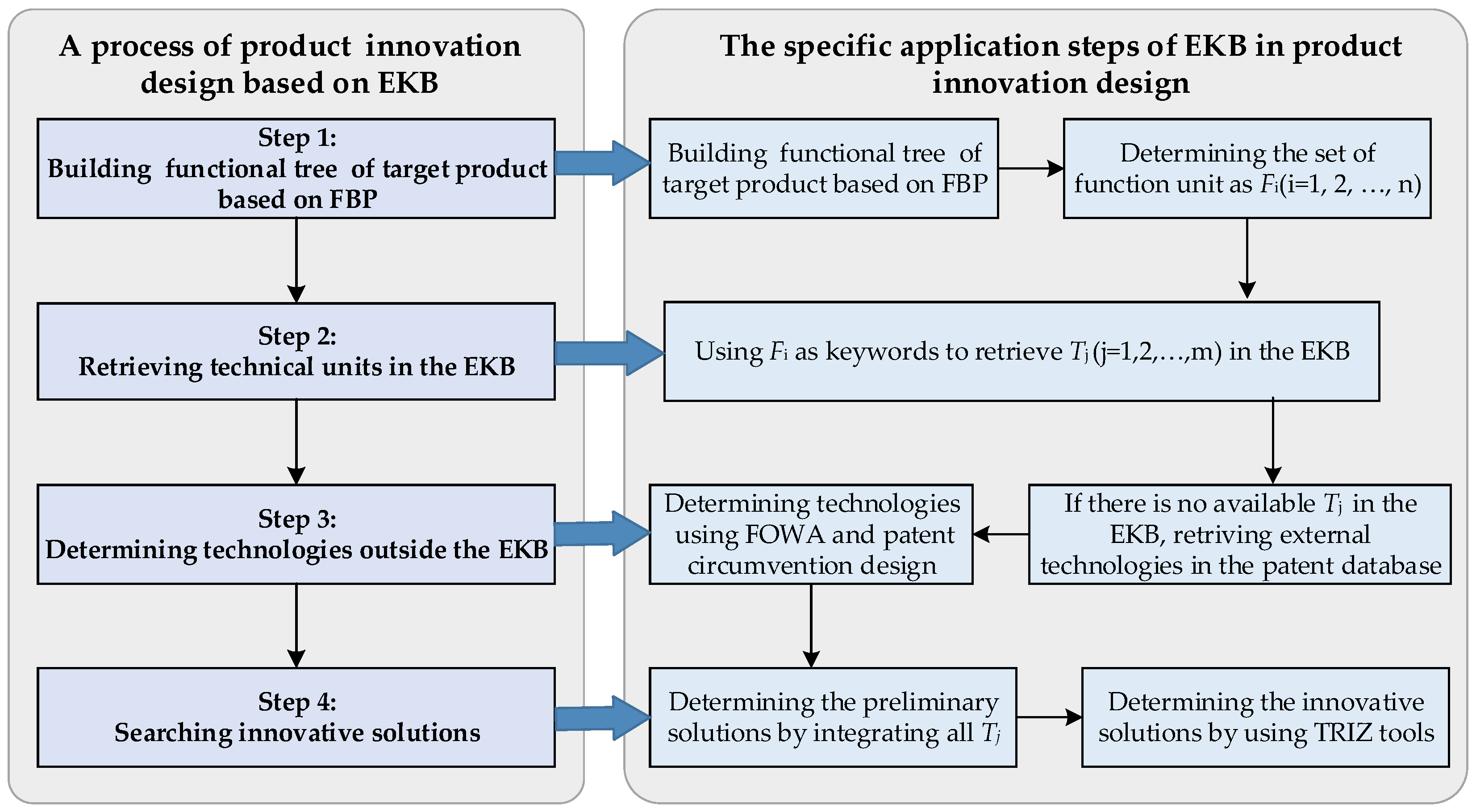
The construction process of an EKB proposed in this paper uses the concept of FBP. Because the functional basis proposed by Stone cannot be well adapted to current enterprise product design activities, this paper proposes a method of building functional trees based on FBP. In addition, the FBP is used as the retrieval path of the EKB to search related principles and structures. Compared with the retrieval method based on keywords or codes in the traditional knowledge base, the new retrieval method is easy to operate for engineers and enables them to find knowledge quickly. The organized retrieval process is beneficial to the product innovation design process of an enterprise.
(3)
EKB is one of the important tools in product innovation design. The process based on the EKB presented in this paper provides an operational method for product development for enterprises. The proposed method can effectively utilize the knowledge and technology in the EKB to improve the development of innovation, reduce the difficulty and risk of product development, and encourage enterprises to produce innovative designs. This will attract more enterprises to participate in innovation activities, produce innovative products, reshape the existing market environment, and even accelerate the development of the entire industry.

5.2. Limitations and Suggestions for Further Research

Although the construction method of EKB can greatly improve product development from the perspective of knowledge retrieval and expression, the quantity and quality of knowledge directly affect the efficiency of designers in obtaining solutions. Therefore, it is necessary to continuously add more knowledge to expand the EKB. This paper only proposes the conceptual scheme of EKB. In the future, software development for the EKB is required. In addition, the product innovation design process based on the EKB needs more enterprises in order to be verified and continuously improved.
Our future work will include a software tool development of EKB to enhance its practical application value, which can better serve the product development process of enterprises. In addition, we plan to further promote the product innovation design process based on the EKB for enterprises to develop different products. At the same time, we will continuously improve the EKB and product innovation design process based on the feedback of industrial users.

6. Conclusions

This paper proposes methods of constructing an EKB for the innovative design of mechanical products and the specific process of product innovation design based on EKB. All of the function units are determined by building functional trees based on FBP for similar products. The conceptual scheme of EKB is formed through the mapping relationship between function and technology. Subsequently, the specific application process of EKB in enterprise product innovation design is formulated. Furthermore, the feasibility and effectiveness of the proposed method were verified through the design process of the underwater separator. Lastly, the implications of the proposed method are concluded with a discussion about its limitations and suggestions for further research.

Author Contributions

Conceptualization, L.Z. and R.T.; methodology, L.Z. and R.T.; writing—original draft preparation, L.Z.; data curation, K.W.; writing—review and editing, Q.P.; visualization, P.S. and Y.D.; funding acquisition, R.T. All authors have read and agreed to the published version of the manuscript.

Funding

This research was funded by the National Natural Science Foundation of China of Runhua Tan, grant number 51675159, the Central Government Guides Local Science and Technology Development Project of China of Runhua Tan, grant number 18241837G, the National Natural Science Foundation of China of Fei Yu, grant number 51805142.

Institutional Review Board Statement

Not applicable.

Informed Consent Statement

Not applicable.

Data Availability Statement

The data that support the findings of this study are available in [Pastsnap] at [https://analytics.zhihuiya.com] (accessed on 28 March 2022).

Conflicts of Interest

The authors declare no conflict of interest.

References

  1. Verganti, R.; Vendraminelli, L.; Iansiti, M. Innovation and design in the age of artificial intelligence. J. Prod. Innov. Manage. 2020, 37, 212–227. [Google Scholar] [CrossRef]
  2. Zhang, M.; Zhao, X.; Lyles, M. Effects of absorptive capacity, trust and information systems on product innovation. Int. J. Oper. Prod. Manage. 2018, 38, 493–512. [Google Scholar] [CrossRef] [Green Version]
  3. Shao, X.; Zhou, Y. Strategic significance and technical route of “NC Generation” mechanical product innovation project. Chin. Mech. Eng. 2012, 23, 1. [Google Scholar]
  4. Zhou, J. Digitalization and intelligentization of manufacturing industry. Adv. Manuf. 2013, 1, 1–7. [Google Scholar] [CrossRef] [Green Version]
  5. Hsu, W.; Woon, I.M.Y. Current research in the conceptual design of mechanical products. Comput.-Aided Des. 1998, 30, 377–389. [Google Scholar] [CrossRef]
  6. Corso, M.; Martini, A.; Paolucci, E. Knowledge management in product innovation: An interpretative review. Int. J. Manag. Rev. 2001, 3, 341–352. [Google Scholar] [CrossRef]
  7. Un, C.A.; Cuervo-Cazurra, A.; Asakawa, K. R&D collaborations and product innovation. J. Prod. Innov. Manage. 2010, 27, 673–689. [Google Scholar]
  8. Bohm, M.R.; Stone, R.B. Product design support: Exploring a design repository system. In Proceedings of the ASME International Mechanical Engineering Congress and Exposition, Anaheim, CA, USA, 13–20 November 2004. [Google Scholar]
  9. Zhang, D.; Hu, D.; Xu, Y. A Framework for Ontology-Based Product Design Knowledge Management. In Proceedings of the 2010 Seventh International Conference on Fuzzy Systems and Knowledge Discovery, Yantai, China, 10–12 August 2010. [Google Scholar]
  10. Naykhanova, L.V.; Naykhanova, I.V. Conceptual Model of Knowledge Base System. In Proceedings of the International Conference Information Technologies in Business and Industry, Tomsk, Russia, 17–20 January 2018. [Google Scholar]
  11. Gilmore, J.F. Knowledge base systems in computer aided technology. In Proceedings of the 23rd IEEE Conference on Decision and Control, Las Vegas, NV, USA, 12–14 December 1984. [Google Scholar]
  12. Zhongyi, M.; Sanshan, Z.; Younus, M. Research on knowledge-based system for typical aircraft composite component design. Proc. Eng. 2011, 15, 1431–1435. [Google Scholar] [CrossRef] [Green Version]
  13. Philpotts, M. An introduction to the concepts, benefits and terminology of product data management. Ind. Manage. Data Syst. 1996, 96, 11–17. [Google Scholar] [CrossRef]
  14. Panetto, H.; Dassisti, M.; Tursi, A. ONTO-PDM: Product-driven ONTOlogy for Product Data Management interoperability within manufacturing process environment. Adv. Eng. Inform. 2012, 26, 334–348. [Google Scholar] [CrossRef] [Green Version]
  15. Stark, J. Product Lifecycle Management (PLM); Springer: Cham, Switzerland, 2016; pp. 37–45. [Google Scholar]
  16. Weber, C.; Werner, H.; Deubel, T. A different view on Product Data Management/Product Life-Cycle Management and its future potentials. J. Eng. Des. 2003, 14, 447–464. [Google Scholar] [CrossRef]
  17. Gero, D.P. A knowledge representation schema for design. AI Mag. 1990, 11, 26–36. [Google Scholar]
  18. Hubka, V. Principles of Engineering Design; Redwood Burn Ltd.: Trowbrige, UK, 2015. [Google Scholar]
  19. Gero, J.S.; Kannengiesser, U. The situated function–behaviour–structure framework. Des. Stud. 2004, 25, 373–391. [Google Scholar] [CrossRef]
  20. Brodie, M.; Mylopoulos, J. On Knowledge Base Management Systems: Integrating Artificial Intelligence and Database Technologies; Springer-Verlag: New York, NY, USA, 1986. [Google Scholar]
  21. Davydenko, I.T. Ontology-Based Knowledge Base Design; Belarussian State Universityof Informatics and Radioelectronics: Minska, Belarus, 2017. [Google Scholar]
  22. Tsang, Y.P.; Wu, C.H.; Lin, K.Y. Unlocking the power of big data analytics in new product development: An intelligent product design framework in the furniture industry. J. Manuf. Syst. 2022, 62, 777–791. [Google Scholar] [CrossRef]
  23. He, D.J.; Song, X.; Wang, Q. Method for complex product collaborative design based on cloud service. CIMS. 2011, 17, 533–539. [Google Scholar]
  24. Ye, Y.; Hu, T.; Zhang, C. Design and development of a CNC machining process knowledge base using cloud technology. Int. J. Adv. Manuf. Technol. 2018, 94, 3413–3425. [Google Scholar] [CrossRef]
  25. Luo, X.C.; Huang, N. Constructing a constraint net during the modeling stage of aircraft product design. In Proceedings of the 2005 IEEE International Technology Management Conference, Munich, Germany, 20–22 June 2005. [Google Scholar]
  26. Jayakiran, R.E.; Sridhar, C.N.V.; Pandu, R.V. Research and Development of Knowledge Based Intelligent Design System for Bearings Library Construction Using SolidWorks API; Springer International Publishing: Cham, Switzerland, 2016; pp. 311–319. [Google Scholar]
  27. Dong, X.; Zhang, W.; Yang, K. Research on intelligent design method and application of cable route for offshore platform. Shipbuild. China 2021, 42, 213–230. [Google Scholar]
  28. Wang, T.C.; Hu, X.X.; Zhong, S.S. Research on extension knowledge base system for scheme design of mechanical product. Math. Model. Eng. Probl. 2016, 3, 141–145. [Google Scholar] [CrossRef]
  29. Zhang, J.Y.; An, L.L.; Li, W. Research and development of knowledge base system for process design of composite-structure. Aeronaut. Manuf. Technol. 2015, 18, 60–63. [Google Scholar]
  30. Mesihovic, S.; Malmqvist, J.; Pikosz, P. Product data management system-based support for engineering project management. J. Eng. Des. 2004, 15, 389–403. [Google Scholar] [CrossRef]
  31. Peltonen, H. Concepts and an Implementation for Product Data Management; Finnish Academy of Technology: Helsinki, Finland, 2000; pp. 1–188. [Google Scholar]
  32. Ahmed, Z. Proposing semantic-oriented agent and knowledge base product data management. Inf. Manag. Comput. Secur. 2009, 17, 360–371. [Google Scholar] [CrossRef]
  33. Li, Q.; Liu, Y. Research and application of heterogeneous PDM System integration technology based on Web Service technology. Digit. Technol. Appl. 2020, 38, 148–151. [Google Scholar]
  34. Ostroukh, A.V.; Gusenitsa, D.O.; Golubkova, V.B. Integration of PDM and ERP systems within a unified information space of an enterprise. IOSR-JCE 2014, 16, 31–33. [Google Scholar] [CrossRef]
  35. Liu, D.T.; Xu, X.W. A review of web-based product data management systems. Comput. Ind. 2001, 44, 251–262. [Google Scholar]
  36. Gao, J.X.; Aziz, H.; Maropoulos, P.G. Application of product data management technologies for enterprise integration. Int. J. Comput. Integr. Manuf. 2003, 16, 491–500. [Google Scholar] [CrossRef]
  37. Kropsu-Vehkapera, H.; Haapasalo, H.; Harkonen, J. Product data management practices in high-tech companies. Ind. Manag. Data Syst. 2009, 109, 758–774. [Google Scholar] [CrossRef] [Green Version]
  38. Otto, B. Managing the business benefits of product data management: The case of Festo. J. Enterp. Inf. Manag. 2012, 25, 272–297. [Google Scholar] [CrossRef]
  39. Matsokis, A.; Kiritsis, D. An ontology-based approach for Product Lifecycle Management. Comput. Ind. 2010, 61, 787–797. [Google Scholar] [CrossRef]
  40. Sudarsan, R.; Fenves, S.J.; Sriram, R.D. A product information modeling framework for product lifecycle management. Comput.-Aided Des. 2005, 37, 1399–1411. [Google Scholar] [CrossRef]
  41. Srinivasan, V. An integration framework for product lifecycle management. Comput. Aided Des. 2011, 43, 464–478. [Google Scholar] [CrossRef]
  42. Wiesner, S.; Freitag, M.; Westphal, I. Interactions between service and product lifecycle management. Proc. CIRP 2015, 30, 36–41. [Google Scholar] [CrossRef]
  43. Paavel, M.; Karjust, K.; Majak, J. Development of a product lifecycle management model based on the fuzzy analytic hierarchy process. Proc. Estonian Acad. Sci. 2017, 66, 279–286. [Google Scholar] [CrossRef]
  44. Makino, K.; Sawaguchi, M.; Miyata, N. Research on functional analysis useful for utilizing TRIZ. Proc. Eng. 2015, 131, 1021–1030. [Google Scholar] [CrossRef] [Green Version]
  45. Timothy, W.; Simpson. Product Platform and Product Family Design: Methods and Applications; Springer Science & Business Media: New York, NY, USA, 2006. [Google Scholar]
  46. Atilola, O.; Tomko, M.; Linsey, J.S. The effects of representation on idea generation and design fixation: A study comparing sketches and function trees. Des. Stud. 2016, 42, 110–136. [Google Scholar] [CrossRef] [Green Version]
  47. Dong, Y.; Tan, R.; Zhang, P. Product redesign using functional backtrack with digital twin. Adv. Eng. Inform. 2021, 49, 101361. [Google Scholar] [CrossRef]
  48. Liu, H.; Huo, Z.; Cao, G. A Sustainable Model of Function Decomposition Based on Effect; Springer: Berlin/Heidelberg, Germany, 2011; pp. 1–6. [Google Scholar]
  49. Cascini, G.; Rotini, F.; Russo, D. Functional modeling for TRIZ-based evolutionary analyses. In Proceedings of the International Conference on Engineering Design, Stanford University, Stanford, CA, USA, 24–27 August 2009. [Google Scholar]
  50. Sun, J.; Tan, R. Method for forecasting DI based on TRIZ technology system evolution theory. Int. J. Technol. Manage. 2012, 9, 1250010. [Google Scholar] [CrossRef]
  51. Shupe, J.A.; Mistree, F.; Sobieszanski-Sobieski, J. Compromise: An effective approach for the hierarchical design of structural systems. Comput. Struct. 1987, 26, 1027–1037. [Google Scholar] [CrossRef]
  52. Suh, N.P. Axiomatic design theory for systems. Res. Eng. Des. 1998, 10, 189–209. [Google Scholar] [CrossRef]
  53. Guo, J.; Peng, Q.; Zhang, L. Estimation of product success potential using product value. Int. J. Prod. Res. 2021, 59, 5609–5625. [Google Scholar] [CrossRef]
  54. Zhang, J.; Tan, R. Radical Concept Generation Inspired by Cross-Domain Knowledge. Appl. Sci. 2022, 12, 4929. [Google Scholar] [CrossRef]
  55. Collins, J.A.; Hagan, B.T.; Bratt, H.M. The failure-experience matrix—A useful design tool. J. Eng. Ind. 1976, 98, 1074–1079. [Google Scholar] [CrossRef]
  56. Beitz, W.; Pahl, G.; Grote, K. Engineering design: A systematic approach. MRS Bull. 1996, 21, 71. [Google Scholar]
  57. Hundal, M.S. A systematic method for developing function structures, solutions and concept variants. Mech. Mach. Theory. 1990, 25, 243–256. [Google Scholar] [CrossRef]
  58. Lind, M. Modeling goals and functions of complex industrial plants. Appl. Artif. Intell. 1994, 8, 259–283. [Google Scholar] [CrossRef]
  59. Altshuller, G.S. Creativity as an Exact Science: The Theory of the Solution of Inventive Problems; Gordon and Breach Science Publishers: Philadelphia, PA, USA, 1984. [Google Scholar]
  60. Stone, R.B.; Wood, K.L. Development of a Functional Basis for Design. In Proceedings of the International Design Engineering Technical Conferences and Computers and Information in Engineering Conference, Las Vegas, NV, USA, 12–16 September 1999. [Google Scholar]
  61. Stone, R.B.; Wood, K.L.; Crawford, R.H. A heuristic method for identifying modules for product architectures. Des. Stud. 2000, 21, 5–31. [Google Scholar] [CrossRef]
  62. Stone, R.B.; Wood, K.L.; Crawford, R.H. Using quantitative functional models to develop product architectures. Des. Stud. 2000, 21, 239–260. [Google Scholar] [CrossRef]
  63. Hirtz, J.; Stone, R.B.; McAdams, D.A. A functional basis for engineering design: Reconciling and evolving previous efforts. Res. Eng. Des. 2002, 13, 65–82. [Google Scholar] [CrossRef]
  64. Stroble, J.K.; Watkins, S.E.; Stone, R.B. Modeling the Cellular Level of Natural Sensing with the Functional Basis For The Design of Biomimetic Sensor Technology. In Proceedings of the 2008 IEEE Region 5 Conference, Kansas City, MO, USA, 17–20 April 2008. [Google Scholar]
  65. Yoon, J.; Park, H.; Seo, W. Technology opportunity discovery (TOD) from existing technologies and products: A function-based TOD framework. Technol. Forecast. Soc. Chang. 2015, 100, 153–167. [Google Scholar] [CrossRef]
  66. Cheong, H.; Li, W.; Cheung, A. Automated extraction of function knowledge from text. J. Mech. Des. 2017, 139, 111407. [Google Scholar] [CrossRef]
  67. Liu, L.; Li, Y.; Xiong, Y. A new function-based patent knowledge retrieval tool for conceptual design of innovative products. Comput. Ind. 2020, 115, 103154. [Google Scholar] [CrossRef]
  68. Szykman, S.; Racz, J.W.; Sriram, R.D. The representation of function in computer-based design. In Proceedings of the ASME 1999 Design Engineering Technical Conference, Las Vegas, NV, USA, 12–16 September 1999. [Google Scholar]
  69. Szykman, S.; Sriram, R.; Smith, S. Proceedings of the NIST Design Repository Workshop; National Institute of Standards and Technology: Gaithersburg, MD, USA, 1996. [Google Scholar]
  70. Tan, R. Eliminating technical obstacles in innovation pipelines using CAIs. Comput.Ind. 2011, 62, 414–422. [Google Scholar]
  71. Tan, R.; Ma, J.; Liu, F. UXDs-driven conceptual design process model for contradiction solving using CAIs. Comput. Ind. 2009, 60, 584–591. [Google Scholar] [CrossRef]
  72. Fey, V.; Rivin, E. Innovation on Demand: New Product Development using TRIZ; Cambridge University Press: Cambridge, UK, 2005. [Google Scholar]
  73. Yuan, F.; Wang, T.; Nie, H. Function and principle innovative design of mechanical products based on TRIZ/FA. Front. Mech. Eng. 2006, 1, 350–355. [Google Scholar] [CrossRef]
  74. Cheng, S.; Mi, J.; Zhao, R. Patent product innovation re-design based on function analysis. Recent Pat. Mech. Eng. 2016, 9, 71–78. [Google Scholar] [CrossRef]
  75. Cao, G.Z.; Tan, R.H.; Sun, J.G. Process and realization of functional design based on extended-effect Model. J. Mech. Eng. 2009, 45, 157–167. [Google Scholar] [CrossRef]
  76. Cao, G.Z.; Tan, R.H.; Sun, J.G. The Principle and Application of Functional Design, 1st ed.; Higher Education Press: Beijing, China, 2016; pp. 1–296. [Google Scholar]
  77. Litvin, S. New TRIZ-based tool—function-oriented search (FOS). In Proceedings of the TRIZ Future Conference, Florence, Italy, 3–5 November 2004. [Google Scholar]
  78. Montecchi, T.; Russo, D. FBOS: Function/behaviour–oriented search. Proc. Eng. 2015, 131, 140–149. [Google Scholar] [CrossRef] [Green Version]
  79. Patsnap. Available online: https://analytics.zhihuiya.com (accessed on 3 March 2022).
  80. Baghapour, M.A.; Shooshtarian, M.R. Extending a consensus-based fuzzy ordered weighting average (FOWA) model in new water quality indices. Iran. J. Health Saf. Environ. 2017, 4, 824–834. [Google Scholar]
  81. Golfam, P.; Ashofteh, P.S.; Loáiciga, H.A. Evaluation of the VIKOR and FOWA multi-criteria decision making methods for climate-change adaptation of agricultural water supply. Water Resour. Manag. 2019, 33, 2867–2884. [Google Scholar] [CrossRef]
  82. Li, M.; Ming, X.; Zheng, M. A framework of product innovative design process based on TRIZ and Patent Circumvention. J. Eng. Des. 2013, 24, 830–848. [Google Scholar] [CrossRef]
  83. Li, H.; Yuan, J.F.; Tan, R.H. Design around bundle patent portfolio based on technological evolution. Chin. J. Mech. Eng. 2019, 32, 1–16. [Google Scholar] [CrossRef] [Green Version]
  84. Ramírez-Rios, L.Y.; Camargo-Wilson, C.; Olguín-Tiznado, J.E.; López-Barreras, J.A.; Inzunza-González, E.; García-Alcaraz, J.L. Design of a modular plantar orthosis system through the application of TRIZ methodology tools. Appl. Sci. 2021, 11, 2051. [Google Scholar] [CrossRef]
  85. Li, M.; Ming, X.; He, L.; Zheng, M.; Xu, Z. A TRIZ-based trimming method for patent design around. Comput. Aided Des. 2015, 62, 20–30. [Google Scholar] [CrossRef]
  86. Feng, L.; Niu, Y.; Wang, J. Development of morphology analysis-based technology roadmap considering layer expansion paths: Application of TRIZ and text mining. Appl. Sci. 2020, 10, 8498. [Google Scholar] [CrossRef]
  87. Boavida, R.; Navas, H.; Godina, R. A combined use of TRIZ methodology and eco-compass tool as a sustainable innovation model. Appl. Sci. 2020, 10, 3535. [Google Scholar] [CrossRef]
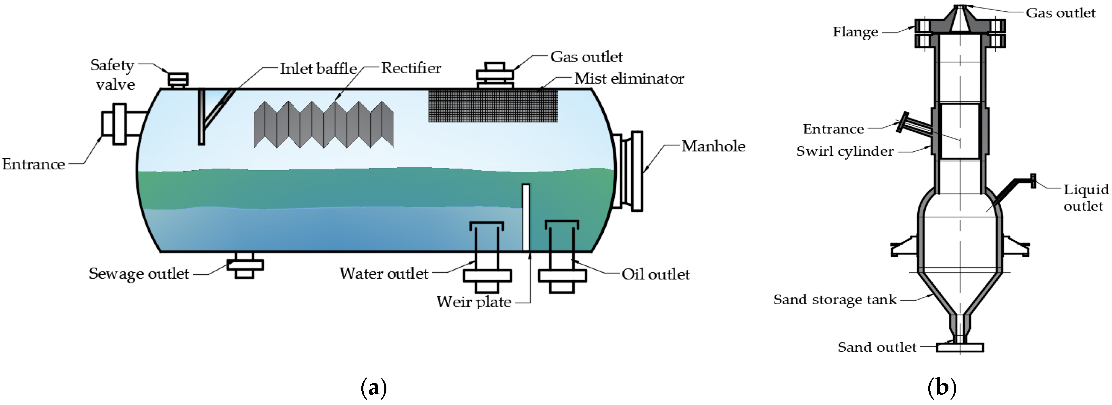
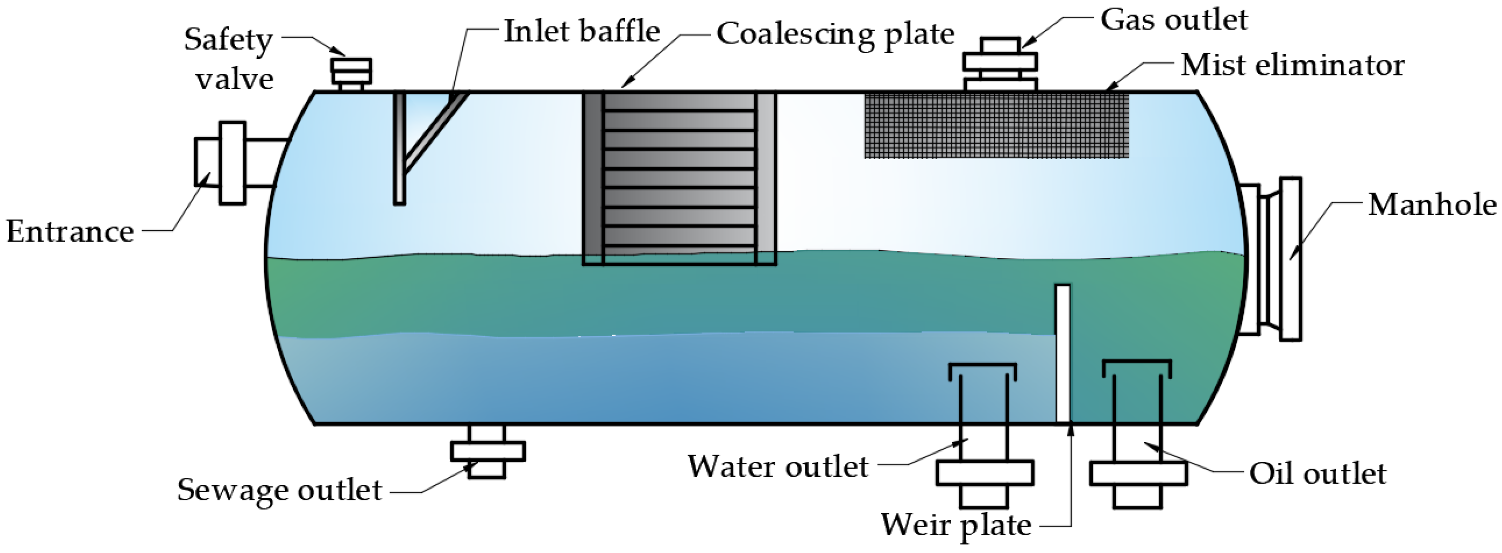
  88. Dong, T.Y. Research on Gas-Liquid Separation Device and Control System of Subsea Separator. Master’s Thesis, M-Harbin Engineering University, Heilongjiang, China, 2018. [Google Scholar]
Figure 1. Functional tree of the product.
Applsci 12 06358 g001
Figure 2. Structure of the technology system.
Applsci 12 06358 g002
Figure 3. The mapping relationship between function units and technical units of one product.
Applsci 12 06358 g003
Figure 4. The construction process of EKB based on FBP.
Applsci 12 06358 g004
Figure 5. The relationship between the modules of the EKB.
Applsci 12 06358 g005
Figure 6. (a) The login interface of EKB; (b) The knowledge retrieval interface of EKB.
Applsci 12 06358 g006
Figure 7. The knowledge about “open nuts” in the EKB.
Applsci 12 06358 g007
Figure 8. (a) Select the function unit; (b) Determine the principle; (c) Select the structure; (d) View the drawing.
Applsci 12 06358 g008
Figure 9. The process of product innovation design based on EKB.
Applsci 12 06358 g009
Figure 10. (a) The structure of a gravity separator; (b) The structure of a centrifugal separator.
Applsci 12 06358 g010
Figure 11. The structure of a collision coalescing separator.
Applsci 12 06358 g011
Figure 12. Functional tree of gravity separator and collision coalescing separator.
Applsci 12 06358 g012
Figure 13. Functional tree of centrifugal separator.
Applsci 12 06358 g013
Figure 14. The mapping relationship between function units and technical units of separators.
Applsci 12 06358 g014
Figure 15. The knowledge retrieval interface of EKB.
Applsci 12 06358 g015
Figure 16. The all knowledge of EKB.
Applsci 12 06358 g016
Figure 17. Functional tree of automatic sand discharge separator.
Applsci 12 06358 g017
Figure 18. (a) Discharge sand by centrifugal sedimentation; (b) Discharge sand by Gravity.
Applsci 12 06358 g018
Figure 19. The structure of sand discharge device.
Applsci 12 06358 g019
Figure 20. The sub-field model of solution.
Applsci 12 06358 g020
Figure 21. The structure of sand discharge device.
Applsci 12 06358 g021
Figure 22. The structure of the automatic sand discharge separator.
Applsci 12 06358 g022
Figure 23. (a) Principle layer interface for sand discharge sand in EKB; (b) The display interface of the sand discharge device in EKB.
Applsci 12 06358 g023
Table 1. The concepts of function.
ConceptsExplanation
Product FunctionInput/output relationship of the total product task in the form of “verb + noun”.
Sub-functionInput/output relationship of product sub-tasks in the form of “verb + noun”.
FunctionOperation of a component or product in the form of “verb”.
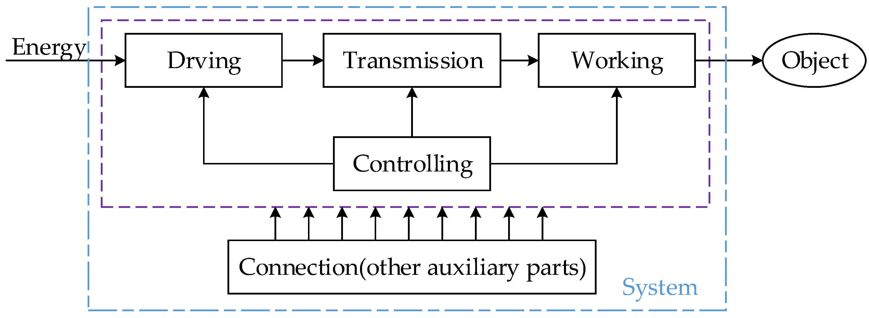
FlowEnergy, materials, and signals as recipients of functional operations.
Functional BasisFunction sets and flow sets.
Table 2. Two technologies for realizing the transmission of torque.
FunctionTechnology
Transmit torqueP
Applsci 12 06358 i001
S1 (interference fit)S2 (clamping connection)
Applsci 12 06358 i002 Applsci 12 06358 i003
Table 3. Values and meaning of triangular fuzzy numbers.
ValueMeaning
0.9The former is more important than the latter.
0.7The former is important compared to the latter.
0.5Both are equally important.
0.3The latter is important compared to the former.
0.1The latter is more important than the former.
0.8, 0.6, 0.4, 0.2Median of adjacent meanings.
Table 4. Technologies through retrieving patents.
No.Patent NumberPatent NameExplanation
1CN113374010BRiver silt and mud cleaner for water conservancy projectsThe brush and water work together to remove the sludge.
2CN101291746BMud ShakerSolids are removed from the sieve by shaking.
3CN111438003AA centrifuge for the preparation of disinfecting bath liquidUsing high-pressure water to remove residual slag.
4CN211690504UA lake bottom sludge suction deviceThe mud is sucked in by the negative pressure generated by the vacuuming device and discharged by the pressurizing device.
5CN213111146UA magnetic suction conveyorMagnetic solids are moved by magnetic traction.
Publisher’s Note: MDPI stays neutral with regard to jurisdictional claims in published maps and institutional affiliations.

