Article

Design and Manufacture of a Flexible Pneumatic Soft Gripper

College of Mechanical and Electrical Engineering, Shaanxi University of Science and Technology, Xi’an 710021, China
*
Author to whom correspondence should be addressed.
Appl. Sci. 2022, 12(13), 6306; https://doi.org/10.3390/app12136306
Submission received: 8 May 2022 / Revised: 15 June 2022 / Accepted: 15 June 2022 / Published: 21 June 2022
(This article belongs to the Topic Space Robotics)

Abstract

:
The soft robot has many degrees of freedom, strong environmental adaptability, and good human–computer interaction ability. As the end-effector of the soft robot, the soft gripper can grasp objects of different shapes without destructivity. Based on the theoretical analysis of the soft robot, the kinematics model of the flexible gripper and the theoretical model of the bending deformation of the air cavity were established. Accordingly, the relationship between the bending angle of the soft gripper and the air pressure was determined. Through the application of finite element software, the bending degree of the pneumatic network multi-cavity soft gripper was simulated, and the influence of structural parameters of soft actuator on bending deformation was determined. In addition, the 3D technology conducts the printing of soft gripper fixtures and molds, the injection molds the actuator, and the human–computer interaction interface controls the movement of the gripper. This paper proposes the control and monitoring of the soft gripper are realized through the electrical control module, the air circuit control module, and the sensor group module, and the size of the airflow velocity can be controlled by PWM DC speed regulation. The adaptability of the soft gripper in grasping objects was verified. The results shows that the software gripper possesses good flexibility and can better grasp objects of different shapes.

1. Introduction

With the deepening research on artificial intelligence, computer control, and robot technology, the application of robots has expanded from traditional manufacturing fields to medical operations, disability-assistance services, disaster search and rescue, scientific detection, aerospace, wearable equipment, and other fields. Compared with rigid robots, soft robots are mainly made of soft materials, and their movements depend on the deformation of soft robots themselves. Therefore, their high flexibility, good conformity, excellent adaptability, and better environmental compatibility have attracted wide attention from scholars [1,2,3]. The soft gripper is a branch of the field of soft robots with the design inspiration coming from naturally soft animals, such as jellyfish, octopus, starfish, and so on. The complex grasping and griping postures are realized through the control of force and displacement [4,5]. Common pneumatically driven soft actuators are fiber reinforced soft actuators and multi-cavity pressurized fluid actuators [6,7,8]. The multi-cavity pressure drives the gripper to achieve different degrees of bending deformation of the soft gripper by adjusting the cavity pressure [9]. With light weight and high power, movements such as elongation, bending, and torsion can be achieved by simple controls. In view of these, the application prospect of the multi-cavity pneumatically actuated gripper has been widely concerned by scholars [10,11,12,13,14]. Polygerinos et al. [4] proposed an analytical model for dimensionally enhanced soft pneumatic actuators, which provides a direction for deterministic design of soft actuators. Whitesides et al. [1] developed a six-finger soft gripper suitable for the biochemical field, which can capture living animals. Brown et al. [15] designed a general soft gripper by using the principle of variable stiffness to make the fillers inside the soft gripper reversibly convert between the “fluid-like” state and the “solid-like” state. Yao J.T. et al. [16] designed a closed-clamping soft gripper, which can clamp and release objects by inflating and deflating pneumatic artificial muscles. Lievski F. et al. [1] designed a soft gripper consisting of two layers of materials with different ductility that can produce spiral bending under pressure. Chen X.T. et al. [17] developed a soft gripper based on a honeycomb pneumatic network. By changing the internal pressure of the airbag, the fingertip and long-distance grasping of the object are realized. Prof. Li et al. [18] developed a pneumatic four-finger soft gripper made of hyperelastic materials with variable effective-grasping length by using fibers to constrain pneumatic humanoid fingers and flexible pneumatic soft hands. The pneumatic soft gripper has multiple-grasping mechanisms, which can well grasp a variety of irregular objects and has good grasping effect and commercial prospects. Renda et al. [19] used variable-length soft actuators and embedded flexible materials to establish a geometric steady-state model for simulating an octopus’ claws and designed a continuous manipulator by embedding 12 wire ropes in silica gel to achieve bending, stretching, and grasping. Kim et al. [20] at Seoul University used SMA as the driving element and made soft manipulators based on programmed intelligent soft composite (SSC), which can capture many irregular objects. Cao et al. [21] proposed a nonlinear predictive control strategy SNN-ESGP, which is comprised of a novel model called echo state Gaussian process (ESGP) that is suitable for modeling nonlinear unknown systems as well as measuring their uncertainties, and a single neural network (SNN) serves as the controller of the system. Chavoshian et al. [22] proposes a new hybrid dynamic neural network (DNN) and proportional integral derivative (PID) controller for the position of the PAM. To enhance the proficiency of the controller, the problem under study is designed in the form of an optimization trend. Considering the potential of particle swarm optimization, it has been applied to optimally tune the PID–DNN parameters. To verify the performance of the proposed controller, it has been implemented on a real-time system and compared to a conventional sliding mode controller. Wang et al. [23] uses a servo control system to control the software manipulator to locate the target object.
In this paper, a multi-cavity pneumatic soft gripper is designed, the shape of which is slender and similar to the arc. Besides, the cross section of the gripper is composed of nine nearly inverted, V-shaped, thin-walled network structure cavities in series. Each cavity is independent of each other. There is a ventilation channel at the bottom of the cavity, and the cavity is connected to a closed cavity by the limiting layer. Bending deformation of the actuator occurs by controlling the side to apply pressure to the air. The bottom airway of the cavity makes the air pressure act on each cavity of the actuator at the same time, thus ensuring the flexibility of the actuator. Due to the limitation of the constraint layer at the bottom of the cavity, the axial force is produced at the end of each cavity, and the cavity is bent to the constraint layer by the side air pressure. Through the man–machine interface input pressure and PWM control flow rate, the soft gripper realizes stable capture and release.

2. Design of Soft Gripper

2.1. Design of Fixture for Soft Gripper

According to the principle of bionics and the structural analysis of the pneumatic multi-cavity soft gripper [24], the multi-cavity pneumatic soft gripper is mainly composed of a fixture, chuck, and soft actuator, which are connected to the end of the fixture by the connector in a symmetrical distribution. The angle between the three grippers of the three-gripper fixtures is 120° and that between the four grippers of the four-gripper fixtures is 90°. Besides, each bracket is 85 mm in length with seven slots. The fixture is designed with the software SolidWorks and 3D printing mold. The soft gripper can grab objects with different diameters by adjusting the clamping position on the fixture. Four-gripper and three-gripper fixtures as well as the chuck structure are shown in Figure 1.

2.2. The Design of the Soft Actuator

The design of the soft gripper actuator includes the mold design, 3D printing mold, configuration of silica gel, preparation of limit layer, and casting molding.
(1)
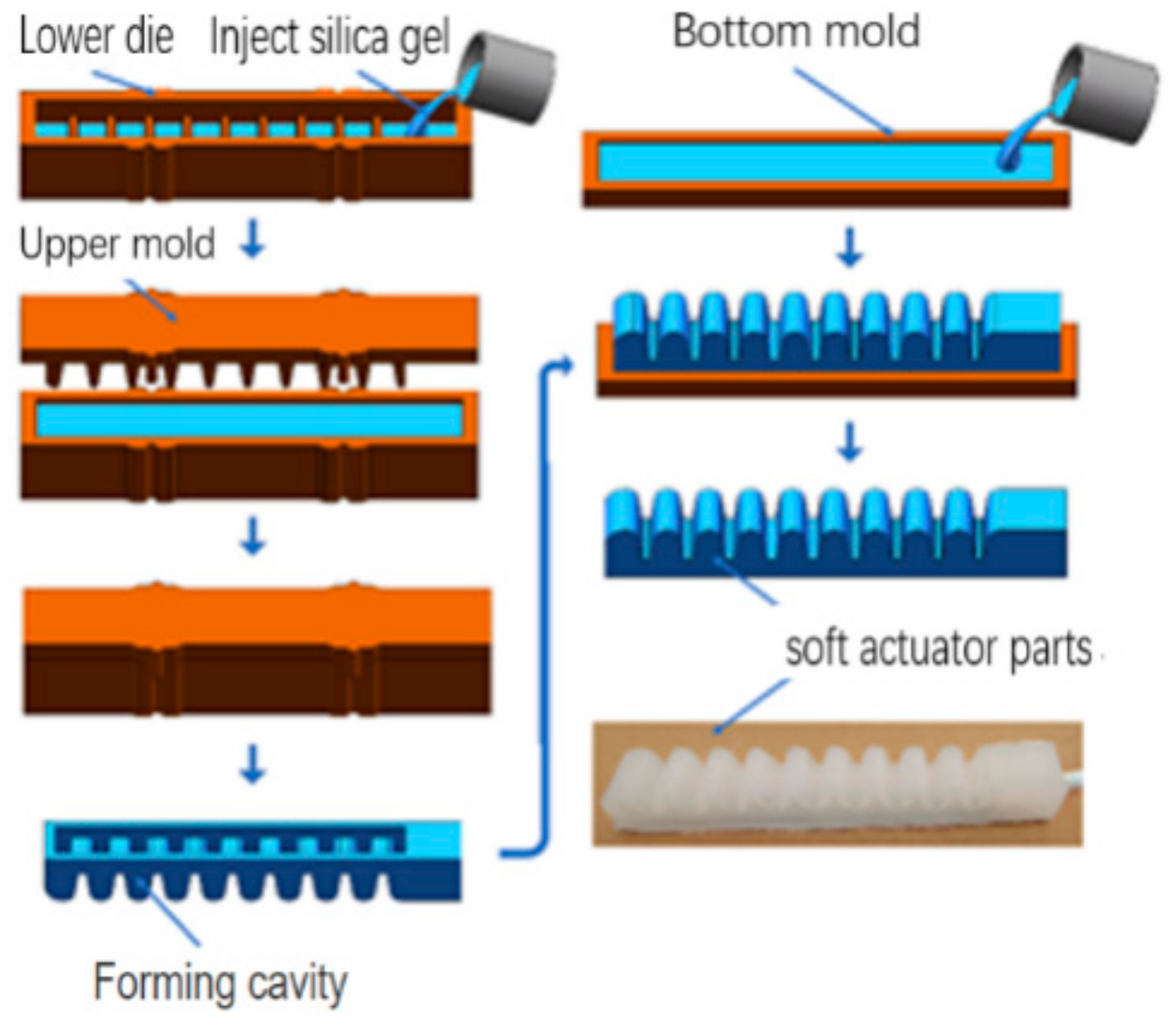
Actuator molding process: The mold of the soft actuator consists of the upper mold, the lower mold, the plug, and the bottom mold. The molds are designed by 3D software UG and 3D printing. The type of 3D printing equipment is model SP600 with a wavelength of 355 nm and accuracy of 0.1 mm. The printing material was 9400 resin, milky white, 320 cps (30°), density 1.14 g/cm, curing depth 0.12 mm (Dp). Since the upper and lower mold surfaces of the soft gripper are closely bonded during the assembly of the mold, the upper and lower mold surfaces are equipped with an exhaust groove to avoid bubbles affecting the quality of the molded products. For the sake of facilitating the connection with the air source, a 3 mm round hole is arranged at the end of the mold, and the inlet pipe connects the actuator and fixture through the round hole. The whole soft actuator is cast by the casting molding method with the main process flow shown in the diagram.
(2)
Preparation of silica gel: Firstly, the silica gel Ecoflex-30 A and B were weighed by electronic weighing and then poured into a small beaker at a mass ratio of 1:1. The bubbles were removed by the vacuum pump for further use.
(3)
Molding of actuator cavity part: Vaseline was smeared on the upper and lower molding surfaces with a small brush to rapidly separate the actuator body from the mold after molding. The deformed silica gel was injected into the lower mold, and the mold should be slightly vibrated during the injection process to ensure the uniformity of the colloid in the cavity. Then, a 3 mm plug was inserted into the fixed position to make the upper and lower mold fully closed. After that, these molds were kept at room temperature for more than 4 h until they were fully cured. Finally, the molds were opened to take out the soft actuator cavity.
(4)
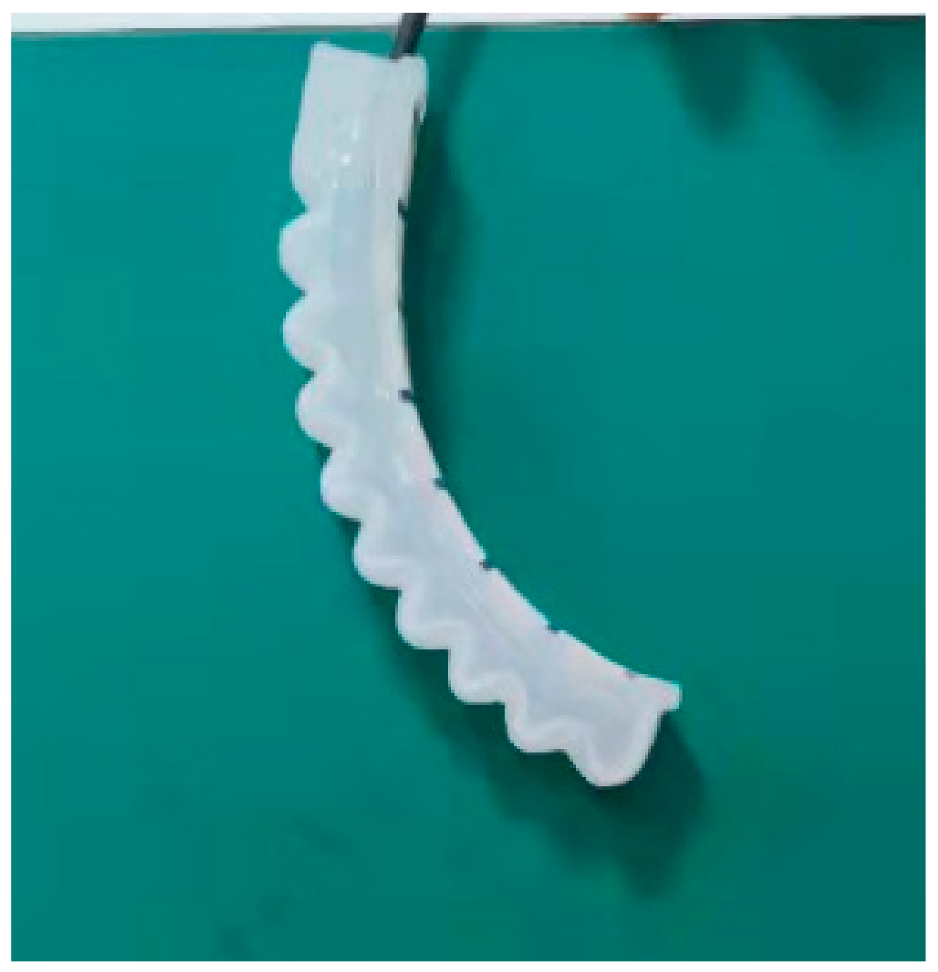
Preparation of the sealing layer: The prepared mixed colloid was injected into the bottom mold to make it evenly spread. On top of it, the nylon cloth limiting layer with a certain size was placed horizontally and smoothly. Besides, a layer of colloid was evenly coated on the nylon cloth. Finally, the actuator cavity was buckled on it. After being kept at room temperature for 4 h, the molds were removed after complete curing. The soft gripper actuator part was thus finished. Pruning molding actuators are mostly silicone rubber, and the actuators that are damaged or bubbled as unqualified parts were discarded.
(5)
Connecting the trachea: A 3 mm diameter trachea was matched with the actuator stomatal channel, and the trachea was inserted into the reserved channel by tweezers. Then, the adhesive at the connection between the trachea and the actuator cavity was evenly smeared. They were kept until firmly sealed. Finally, the air tightness of the actuator was tested by pressurizing air in the actuator.
The same method was adopted to connect three or four tracheas to the soft actuator, and the fixture and the clamp were fixed on the test bench by bolts. At last, the pneumatic soft gripper production was completed, which is shown in Figure 2.
The manufacture of the soft gripper adopted the “split injection molding bonding” method. The soft actuator was completed by two types of silicone injection molds. The outer wall of the cavity in the top strain layer was made of Ecoflex-0030 silica gel with high elasticity, which ensures the greater elongation of the soft gripper. To improve the stiffness of the limiting layer, nylon cloth and E610 silica gel with good stiffness were used for pouring and sealing. Among them, the nylon cloth ensures that the lower layer of the actuator does not have ductility and combines the cavity layer with the outer wall silica gel, thus making the structure of the soft gripper stable and not easily damaged.
The soft gripper has the following characteristics:
(1)
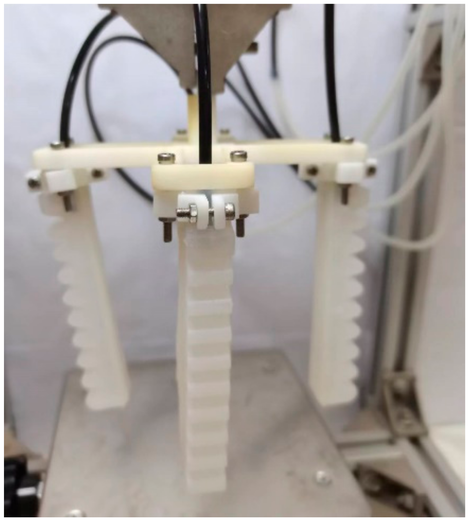
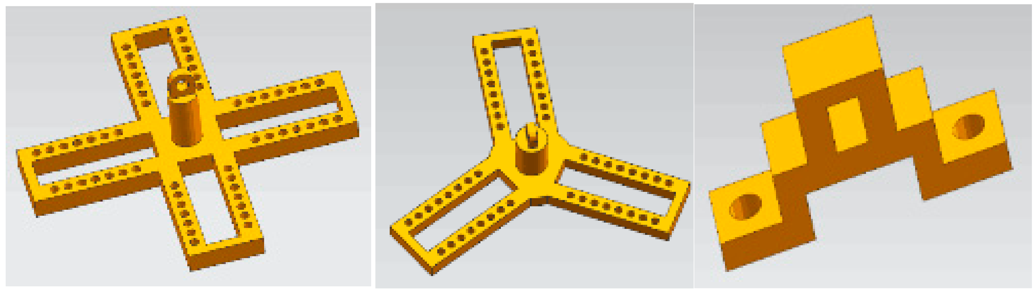
The structure is stable, which enables the three-actuator or four-actuator grippers to grasp objects stably and reliably with different shapes.
(2)
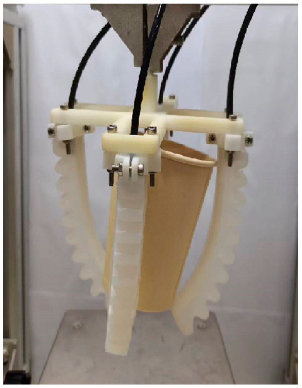
The positions of seven chucks at the connection between the fixture and the actuator can be adjusted, and the bolt is used to tighten the connection after a certain position is determined. When the size of the grasping object changes, the soft gripper does not need to change the fixture, which can be realized by adjusting the position of the card interface connection on the fixture. When the size of the grasping object changes, the position of the bayonet connection on the fixture of the soft gripper is adjusted without the change of the fixture, which is shown in the Figure 3.
(3)
The manipulator possesses strong versatility and practicability with low cost, good flexibility, and easy operation.
(4)
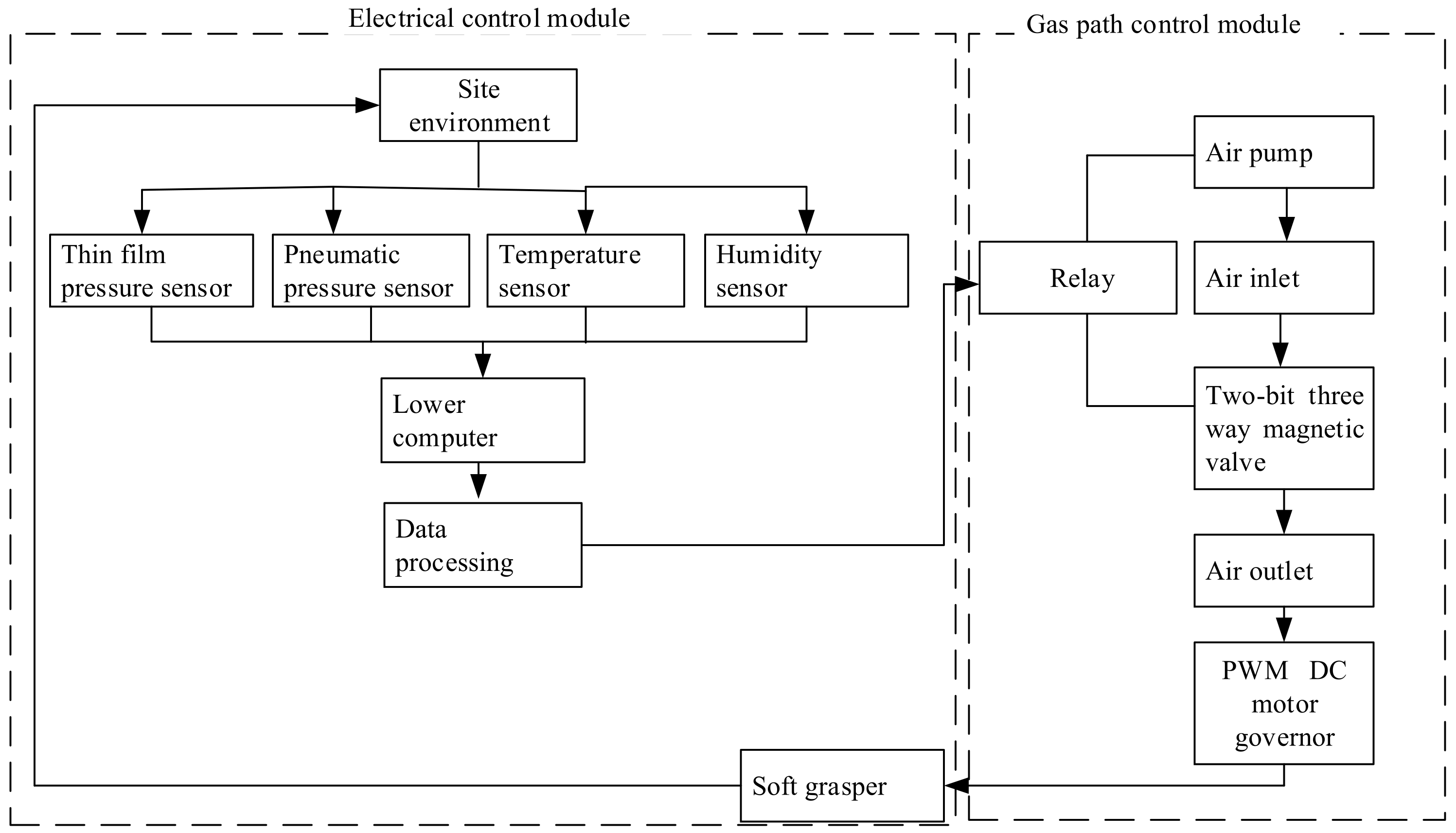
The structure of the soft gripper is optimized, and the control and monitoring of the soft gripper are realized through the electrical control module, air circuit control module, and the sensor group module. Among them, the electrical control module controls the release and retention of pressure in the gas path and realizes data display, instruction sending, early warning prompt, and emergency stop button through the man–machine interface. In the multi-sensor module, the pressure sensor measures the input gas pressure. The film pressure sensor measures the pressure on the soft gripper. The temperature and humidity sensors measure the temperature and humidity of the environment. The gas path module is mainly used to control the gas pressure and velocity of the soft gripper in which the size of the airflow velocity can be controlled by PWM DC speed regulation. In addition, the control system designed by multi-module avoids the limitation of single control and guarantees stable grasping of the soft gripper.
The research on this set of soft grippers provides valuable reference for facilitating the further processing of the lightweight and miniaturized gripper design.

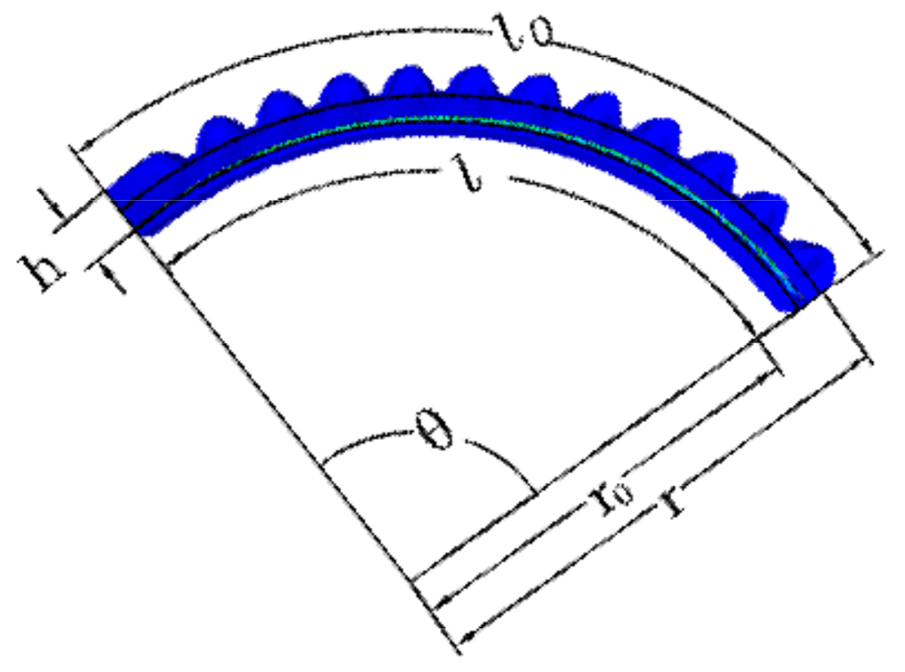
3. Kinematics Model of Soft Gripper

Soft robots have infinite degrees of freedom. The traditional rigid robot-modeling method is no longer applicable to soft robots. The pneumatic network multi-cavity soft actuator is made of super elastic silica gel material, which presents large deformation and nonlinear characteristics during deformation [12]. Due to the isotropic and incompressible properties of hyperelastic materials, the Yeoh model suitable for describing the large deformation of hyperelastic materials was used to establish the constitutive model of the soft actuator [24]. In addition, the analysis was conducted on the bending characteristics of the actuator under working conditions, and the strain energy density function is expressed as W = W I 1 , I 2 , I 3 .
I 1 = λ 1 2 + λ 2 2 + λ 3 2 I 2 = λ 1 2 λ 2 2 + λ 2 2 λ 3 2 + λ 3 2 λ 1 2 I 3 = λ 1 2 λ 2 2 λ 3 2
In the formula, λ1, λ2, and λ3 are the elongation ratios of three directions, respectively; I 1 , I 2 and I 3 are series expansions.
Due to the incompressibility of silica gel materials, Formula (1) can be written as two classical expansions of strain energy density function:
W = C 10 I 1 3 + C 20 I 1 3 2
In the formula: C 10 and C 20 are material constants based on the Yeoh model.
When only the relationship between the axial stress and strain of the soft actuator is considered, the deflection of the principal strain corresponding to the strain energy density function can be obtained; that is, the principal stress strain t, λ1, λ2, and λ3 are as follows.
t = 2 λ 1 λ 1 2 1 λ 1 2 λ 2 2 W I 1 + λ 2 2 W I 2
λ 2 2 = λ 3 2 = 1 λ 1 2
As the bottom of the limiting layer is covered with silica gel, it is assumed that the limiting layer bottom length,   l 0 , does not change after the bending deformation of the soft actuator. Under the action of air pressure, the bending deformation of the soft actuator is shown in Figure 4. According to the geometric relationship, the axial elongation ratio of the actuator, that is, the ratio of the arc length of the middle layer to the arc length of the bottom after the deformation of the actuator, is as follows.
λ 1 = l l 0 = r r 0 = 360 l 0 + 2 π c θ + π h θ 360 l 0
l is the arc length of the actuator center layer; l 0 is the arc length at the bottom of the actuator; r is the bending radius of the middle layer after actuator deformation; r 0 is the bottom bending radius after actuator deformation; θ is the bending angle of the actuator.
The axial cross-sectional area and initial cross-sectional area of the soft actuator can be calculated by s = S 0 λ 2 λ 3 . According to the section equilibrium equation, the relationship between principal stress and driving pressure is obtained as follows:
t = p s 0 s = p λ 2 λ 3
Relationship between bending angle and driving pressure:
θ = 2 π c + π h 2 p 2 129 , 600 l 0 + 360 l 0 p 2 π c + π h 3 + 2 π c + π h 3 3.65 l 0 2

4. Finite Element Simulation of Multi-Cavity Pneumatic Gripper

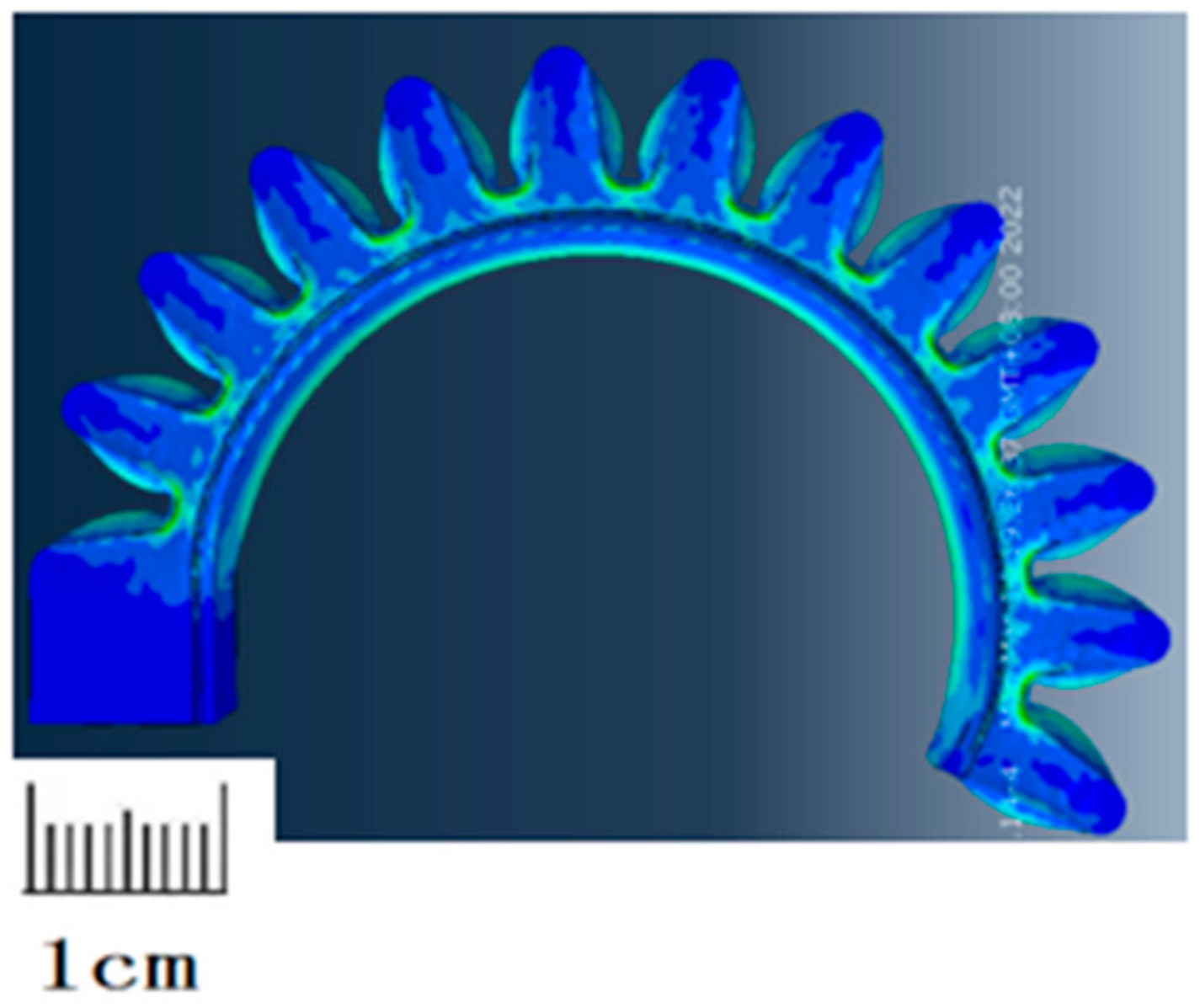
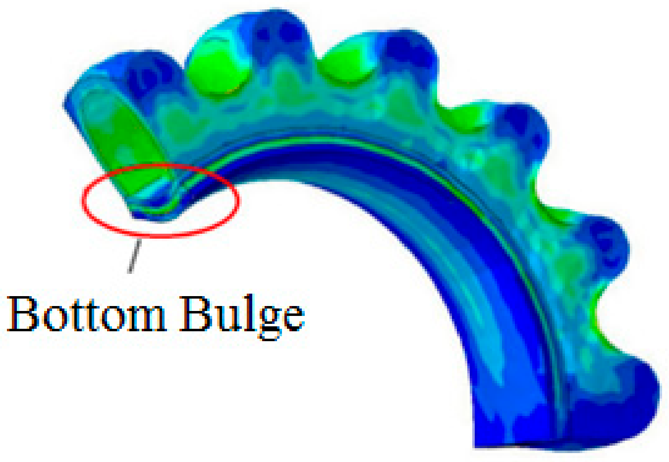
4.1. Simulation of the Bending Deformation of Soft Actuator under Air Pressure

The changes of the structural parameters of the multi-cavity pneumatic soft actuator have different effects on the bending characteristics of the actuator. Therefore, the design principles of constant length, constant height, and constant width were adopted in the analysis of the structural parameters of the actuator. Through experiments and simulations, it is found that wall thickness of the air cavity, height, cavity spacing, the number of cavities, as well as the limiting layer thickness of confinement layer have certain effects on the bending characteristics of the soft actuator.
The main structural material for the cavity molding of the soft gripper actuator is silicone rubber Ecoflex-0030, and the constraint layer at the bottom is silica gel E610. To constrain the ductility of the bottom of the soft gripper, a layer of nylon cloth was embedded between the two layers of silica gel. As the material possesses the characteristics of flexibility, light weight, no ductility, and high hydrophilicity, it is well combined with the E610 silica gel solution.
When the soft gripper was inflated, the gripper tended to expand. Since the stiffness of the limited strain layer material was larger than that of the cavity part with good bending performance but poor axial tensile performance, the deformation of the main material and the limited strain layer material varied a lot, and the local strain difference effect occurred. Therefore, the driving force was transformed into bending moment, resulting in the bending deformation of the whole pneumatic actuator. By changing the geometric structure parameters and material properties of the pneumatic soft actuator, the motion deformation performance was changed. However, the bottom cannot expand due to the constraints of the constraint layer, and large-angle-bending deformation can be realized with the gripper bending to the constraint layer. The bending deformation of a single finger is shown in Figure 5.
In this paper, To characterize the non-linear behavior, a three-order hyperelastic incompressible Yeoh model was adopted for finite element analysis, which was aimed at fully describing the compression and extension phases of the material with coefficients C 1 = 0.11 and C 2 = 0.02. The displacement and rotational constraints were applied to the proximal cap, and the pressure load was applied to the inner wall of the cavity. The solid tetrahedral quadratic hybrid elements (ABAQUS element type C3D10H) were assigned as model grids with ignorance of gravity. The compression and tensile data were plotted in the diagram and fitted with the Yeoh elastic material model in Matlab, as shown in Figure 5.

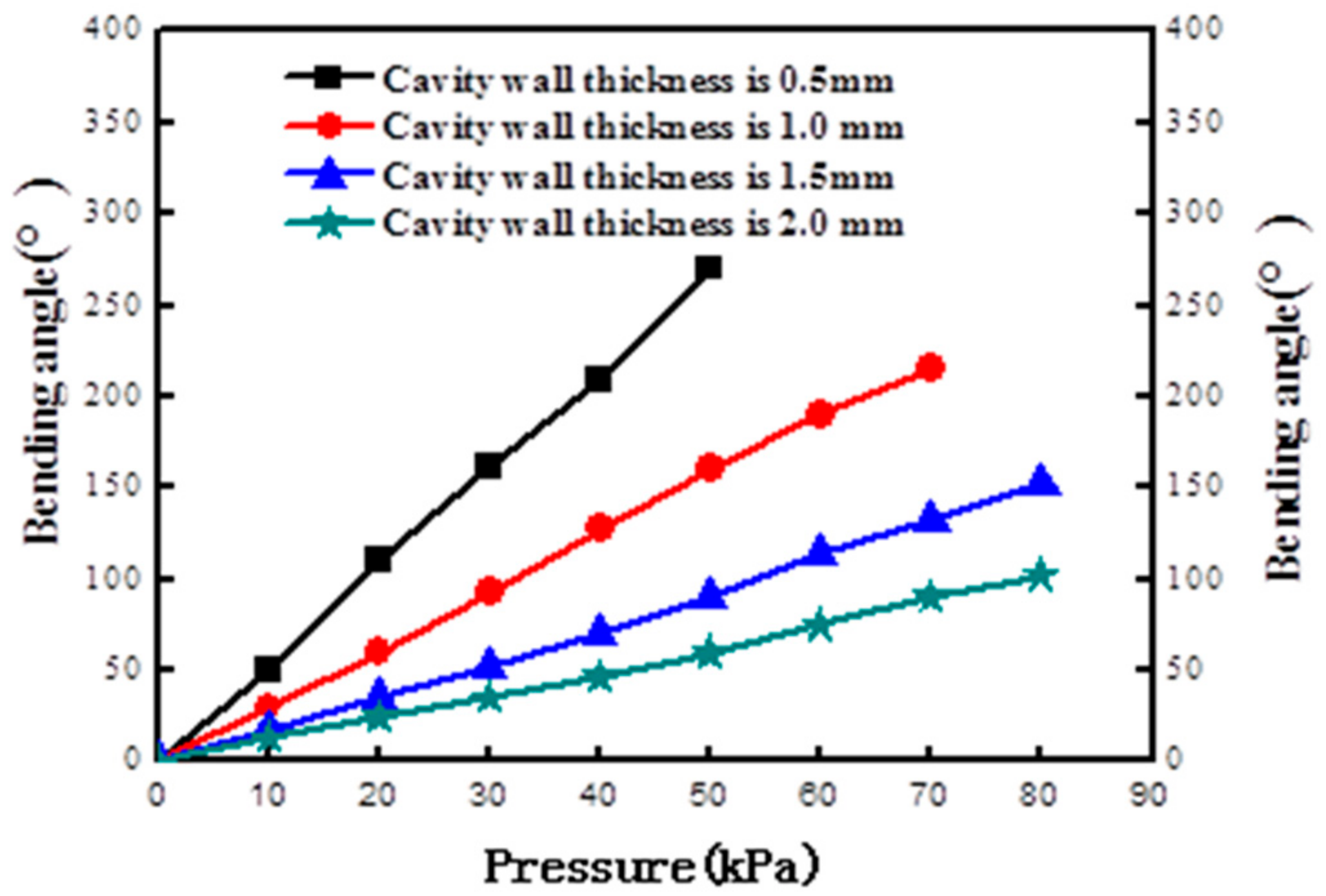
4.2. Simulation of Wall Thickness and Bending Angle of Soft Actuator Cavity

Under the action of the air pressure input on the actuator, the cavity of the excessive pressure actuator deformed to both sides of the drum with the increase in pressure, as shown in Figure 6.
The influence of cavity wall thickness on the bending angle is shown in Figure 7. Besides, the relationship between the bending angle and air pressure of the air cavity wall was stimulated when the cavity wall thickness was 0.5 mm, 1 mm, 1.5 mm, and 2 mm, respectively. Through detailed analysis, it is found that the wall thickness exerted a great influence on the bending angle simulation, which was a key factor affecting the bending deformation performance of the actuator. When the thickness is 0.5 mm, the air pressure reaches about 30 kPa as the cavity wall thickness was thus too thin. Consequently, the bending angle would change quickly, and the simulation graphics show a red warning. When the thickness of the air cavity wall is 1.0 mm, the simulation results show that the bending angle of the actuator tends to be large, and the soft actuator bending is close to 150 degrees after compression reaches about 40 kPa. When the wall thickness is 1 mm and the air pressure is in the range of 0–30 kPa, the soft actuator is linearly related to the air pressure. When the air pressure is above 30 kPa, the air pressure of the soft finger is not linearly related to the bending angle of the finger, and overexpansion occurred. It shows that the expansion ratio of the bending layer is close to the elastic limit of the material. In the actual experiment when other parameters remain unchanged, the wall thickness continues to increase. When it is greater than 2 mm, the bending radius is less than 2 mm. If the wall thickness is 3.0 mm, the bending change of the actuator is very small when the air pressure is too low. Even if the pressure increases to about 90 kPa, the bending amplitude of the soft gripper cannot achieve good results in the actual grasping process; thus, it is not desirable. When the wall thickness is 2.0 mm, the bending angle is in line with that of the expected results as long as the experimental operation can be carried out in the corresponding pressure range. Through comprehensive analysis, 2 mm wall thickness was selected for the experiment under the condition that other parameters remained unchanged.

4.3. Influence of Cavity Height on Bending Angle of Soft Actuator

The cavity wall thickness of the actuator was selected as T = 2 mm. The length of the soft-grasping hand was determined to be 85 mm by referring to the length value of human fingers, which was divided into nine air cavities. The heights, H, of the air cavities were set to be 4–7 mm, respectively, for pressure change simulation. The experimental operation and test were conducted on grabbing objects, and the comparative analysis of the bending situation is shown in Figure 8. When the height of the gas cavities is 4 mm, the bending degree is insufficient. However, if the heights of the gas cavities are 5 mm, 6 mm, and 7 mm, there does not appear to be much difference in bending degree. With the comprehensive experimental analysis, it shows that the height of the soft gripper of 6 mm proves to possess the best bending effect.

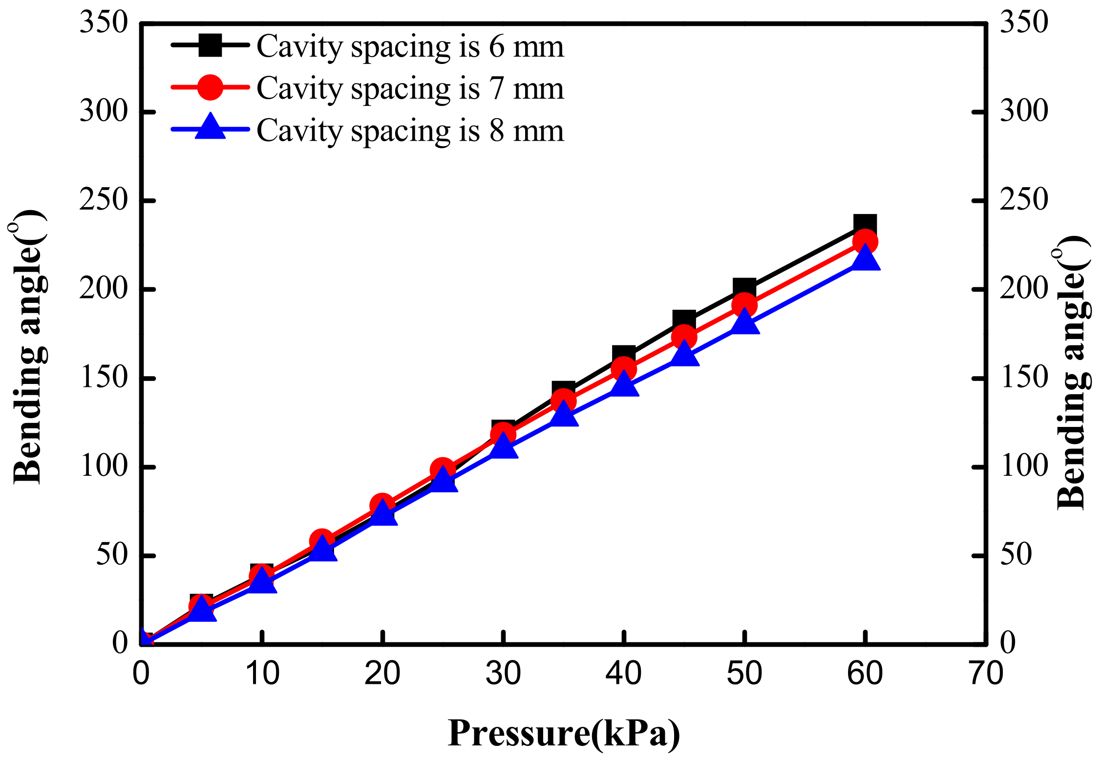
4.4. Influence of Cavity Spacing on Bending Angle of Soft Actuator

The length and width of the soft actuator are 85 mm and 10 mm, respectively, including nine cavities with the spacing between each cavity of 6 mm, 7 mm, and 8 mm, respectively. The wall thickness of the cavity is 2 mm, and the height of the cavity is 6 mm. The three kinds of cavity spacings were simulated by software, respectively, with the results shown in Figure 9. The graph shows that under the same pressure, the smaller cavity spacing contributes to stronger bending degree of the software actuator. Besides, when the cavity spacings are 6 mm and 7 mm, the bending effect is similar. With the decrease of cavity spacing, too small cavity spacing increases the difficulty of mold production and increases the difficulty and error of actual experimental operation. Therefore, it is necessary to use 6 mm spacing for the experiment.

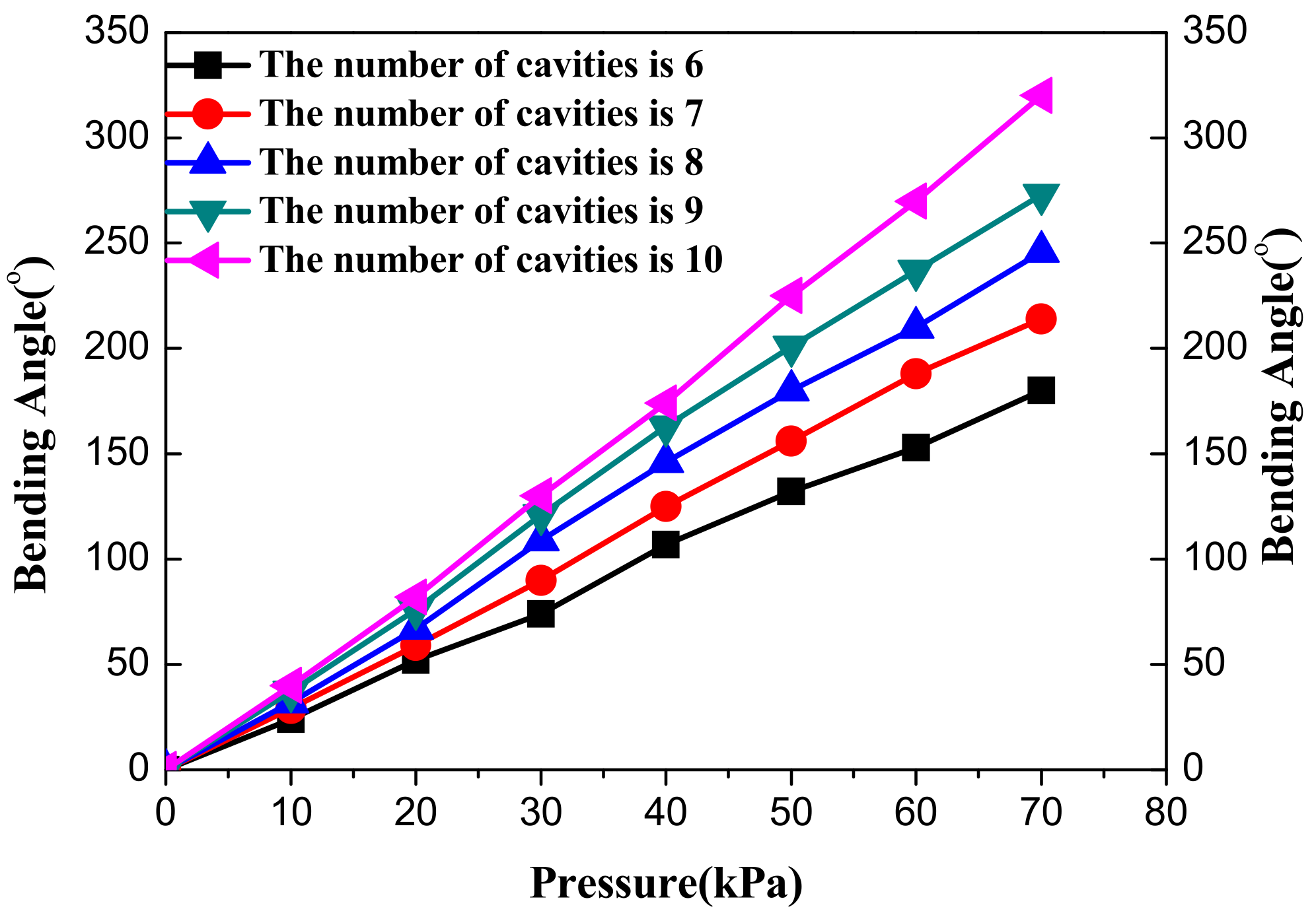
4.5. Effect of the Number of Cavities on Bending Angle of Soft Actuator

If the number of air cavities is too small, the pressure will be insufficient. Thus, this will lead to the small-driving force on the bottom of the soft gripper. Besides, increasing the pressure can increase the bending degree of the soft gripper, but excessive pressure will damage the air cavity, and the air tightness of the soft gripper will also be affected. An excessive number of gas cavities will make the structure complex and redundant. Therefore, the length of a soft gripper and the distance between cavities were first determined, and then soft grippers with six cavities, seven cavities, eight cavities, nine cavities, and ten cavities were selected for simulation analysis. The five kinds of cavity numbers were simulated by software, respectively, with the results shown in Figure 10. The bending degree of the six-cavity soft gripper is poor, while that of the other four are not significantly different under the same air pressure. However, the simulation is an analysis in an ideal state. In the actual experimental operation, if seven cavities are selected, the sealing of the soft gripper will be broken when the air pressure reaches 50 kPa. If 10 mm cavities are selected, the weight of the soft gripper will increase. Therefore, through comprehensive analysis and comparison, the nine-cavity soft gripper was finally used in the experiment.

4.6. Influence of Lower Wall Thickness on Bending Angle of Soft Driver

To achieve a better grasp of objects by the soft gripper, the bottom thickness of the soft gripper is 1.5 mm, 2 mm, 3 mm, and 4 mm, respectively, and the thickness of the nylon cloth of the limiting layer is 0.5 mm. When the thickness of the lower wall is 1.0 mm, there will appear a protrusion at the bottom of the soft actuator with the simulation results shown in Figure 11.
The simulation results of the bottom thickness and bending angle of the soft actuator are shown in Figure 12. The simulation figure shows that the bending angle of the soft actuator is basically linear with the change of pressure. The larger the thickness is, the smaller the bending curvature radius of the soft actuator will be. It is more difficult to operate the experiment with too thick of a confined layer; thus, 2 mm limiting layer thickness was chosen in the experiment.

4.7. Simulation of Grasping Objects with Soft Gripper

To compare and study the grasping reliability of soft fingers, the designed soft fingers were used to grasp apples with diameters of 45 mm. The grasping ability and reliability were analyzed by comparing the contact force and contact area between the fingers and the apples, as shown in Table 1. After modeling soft fingers and apples, finite element analysis was performed. The setting parameters were the internal pressure of the finger is 35 kPa, surface contact between soft gripper and apples, the contact attribute is that the tangential behavior is frictionless, the radial behavior is ‘hard’ contact, the contact surface is set to the lower surface of the finger and the outer surface of the apple, and the soft gripper grasps the arc object to select the apple. The simulation results are shown in Figure 13.
Through the software simulation analysis, a soft gripper was actually made with the structure parameters shown in Table 1.

5. Performance Test of Soft Gripper

To test the performance of the soft gripper, the well-made soft gripper is controlled and actuated by the pneumatic control system composed of Labview software and the Arduino microcontroller. The control system of the soft gripper is shown in Figure 14. The human–machine interface was designed by Labview with Arduino acting as the computer to achieve the joint monitoring and controlling to the soft gripper. The soft gripper was made with the actuation of an air pump, the monitoring of four types of sensors, thin film pressure sensor, pneumatic pressure sensor, temperature sensor, humidity sensor, and the control of a relay module. In the experiment, the control button of the pneumatic control system on the host was operated. Additionally, according to the monitoring environment and the grasping object, the reference pressure value was set on the upper computer and sent to the lower computer for execution to control the pneumatic soft gripper, thus completing the grasping and releasing of objects with different masses and shapes.

5.1. Check for Air Tightness of Soft Actuator

Air leakage of the soft gripper is not allowed in the experiment. Therefore, it is necessary to conduct an air-tightness test for assembling the soft actuator. The adhesive was evenly applied at the connection between the inlet pipe and the actuator, and the man–machine interface was used to conduct the pressurization and pressure-release process. We used a silicone sealant seal the contact between trachea and actuator, it does not affect the performance of the gripper after silicone sealant curing, we can see in Figure 15. Many experiments proved that the soft gripper had good air tightness.

5.2. Determination of Fatigue Limit

The soft actuator is manufactured by the split injection bonding method. The actuator is made of two types of silica gel. The top strain layer is made of high elastic silica gel Ecoflex-0030, and the bottom constraint layer is made of silica gel E610. Nylon cloth is a limiting layer with good elasticity, light weight, non-extensibility, and strong hydrophilicity, which can be well combined with the E610 silica gel solution.
When the soft actuator is inflated, the cavity partially expands, while the bottom cannot expand due to the constraint of the constraint layer. The actuator bends to the constraint layer, which can realize large-angle-bending deformation. During the degassing process, the actuator restores its original shape by shrinking its air cavity. Under the action of air pressure, the actuator can still return to the initial state after many times of repeated bending through the air filling and discharging experiments on a single actuator. It shows that the soft gripper possesses good fatigue resistance, but when the air pressure exceeds a certain value, such as 60 kPa, the soft gripper will appear bulged and continue to press the bulge burst. The results of charging and discharging of the random five fingers is laid out in Table 2.

5.3. Relationship between Bending Angle and Pressure

The soft gripper can achieve bending deformation, mainly because the driving pressure deforms the air cavity of the strain layer and thus produces the interaction force between adjacent gas cavities. If the spacing between the cavities is too large, there will be a lag phenomenon due to the mutual extrusion between adjacent cavities. Thus, the sensitivity of the soft gripper becomes lower. If the bending angle of the soft gripper increases, the pressure of the air needs to be increased. If the spacing between the adjacent cavities is too small, the air pressure will be small and will thus further lead to the occurrence of excessive bending. Moreover, this will even make the extrusion pressure between cavities too large to damage the soft gripper.
In the experiment, the soft actuator was fixed vertically, and the bending angle test was carried out by the angle gauge ruler on the panel. The bending and pressure display of the soft gripper at the same time can be read out from the host panel, which is shown in Figure 16.
The relationship between the bending angle of the flexible actuator and the pressure can be obtained by substituting the actuator parameters in Table 1 into Equation (6). As we can see in Figure 17, the experimental data are lower than the theoretical and simulated data because the simulated data is in an ideal state, the calculation a result of the theoretical data related to models and assumptions, but the experimental data are related to the environment, the performance of the silicone rubber, the force of the gripper, and the curing effect. Therefore, there is a certain gap between the theoretical data and the simulation data. However, this is within permissible error. As a result, the theoretical data in the graphic display approach the simulation data, and the experimental data is smaller.
As can be seen from the results in Figure 18, the bending angle of the actuator increases linearly as the pressure increases. The comparison shows that the theoretical calculation results are consistent with the experimental data and simulation results. In the early stage of deformation, the blocking force of silica gel material causes the measured test data to be low. Thus, the figure shows that there are also some differences between the finite element simulation and the actual experimental results. (1) When the finite element simulation analysis is carried out, the soft gripper is in a completely ideal state, and there may be a phenomenon of uneven division when meshing it. In this case, increasing the pressure may lead to deformity in some parts of the model, which further results in deviation of the simulation results. (2) In the experiment, the accuracy of the 3D printing mold is not enough, and the proportion of silica gel solution mixed ratio cannot guarantee a complete 1:1. (3) When pouring silica gel solution in the mold, the bubble removal is not complete, and the error of artificial reading data affects the experimental data.

5.4. Diameter Test of Grabbing Object by Soft Actuator

To test the grasping ability of the gripper, objects of different shapes and sizes were selected for demonstration. The test results show that the gripper can stably grasp the circular arc apple with a diameter of Φ 45 mm and a weight of 104 g. When the diameter is Φ 50 mm, the soft gripper can achieve adaptive grasping but cannot grasp the larger circular section.

5.5. Grasping Quality Test

In the test, the weight of the test object was simulated by adding 5 g, 2 g, and 1 g weights in a disposable cup. The upper limit of weight that the gripper can grasp at different pressures was tested within the pressure range that the actuator can withstand. In terms of grasping load capacity, the experiment showed that the soft gripper had a certain carrying capacity with the maximum grasping weight of 107 g (Figure 18 and Figure 19).

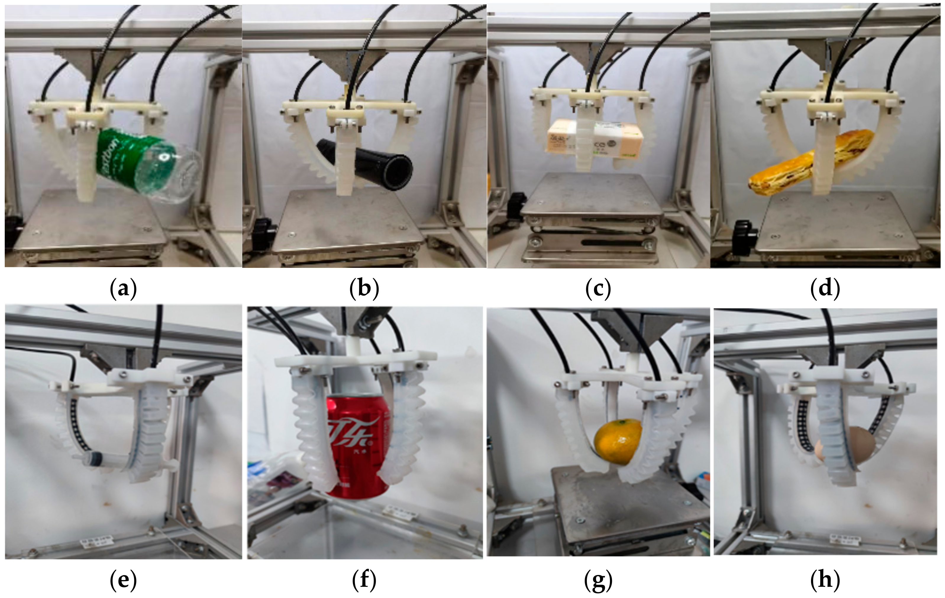
5.6. Multi-Objective Grasping Capability Test

Considering the shape diversity of products, the product shape is abstracted into four types of objects: cylindrical, spherical, rectangular, and special-shaped. Considering the different material properties, the product is abstracted into two types of objects: hard attribute and soft attribute for experiments. Among the different shaped object, all the experiments can be successfully captured and released. On the other hand, it was more difficult to grab the smooth fruit in the experiment, seven times success among ten times grasp. The experimental demonstration diagram is shown in Figure 20.

6. Conclusions

In this paper, an analysis was conducted on the bending deformation of a soft gripper under input pressure. Accordingly, the bending deformation model of an air cavity was established, and the deformation of a soft grip was simulated by finite element software. In addition, with 3D printing technology, printing the fixtures, chucks, and actuator molds on the top of the soft gripper and with the application of the injection mold method, the experimental platform was built to complete the preparation and assembly of a pneumatically actuated soft gripper. Then, tests were carried out on the soft gripper. The theoretical simulation and experiment showed that the soft manipulator presents certain flexibility and can grasp slender objects of different sizes, masses, and shapes, which provides certain reference significance for further research.
(1)
Firstly, ABAQUS finite element software was used to model the soft gripper of the soft robot in a specific environment. In addition, the calculation and analysis were carried out on the thickness of the air cavity of the soft gripper, the distance between adjacent air cavities, the height of the air cavity, the number of air cavities, and the thickness of the bottom. Through the simulation analysis of the bending deformation factors of the soft gripper, the theoretical basis for the preparation of the soft gripper was determined. Through simulation, it is analyzed that the soft gripper was bent and deformed by changing the air pressure in the cavity to improve the load capacity of the gripper and realize the application in various scenarios.
(2)
Secondly, the mold for the preparation of the soft gripper was designed by UG software, and the 3D printer mold was used as the actuator by the injection molding method. A fixture that can automatically adjust the distance between the software claws was made. This fixture is combined with the soft gripper, which enables the manipulator to present strong versatility, practicability, efficiency, good flexibility, and easy operation.
(3)
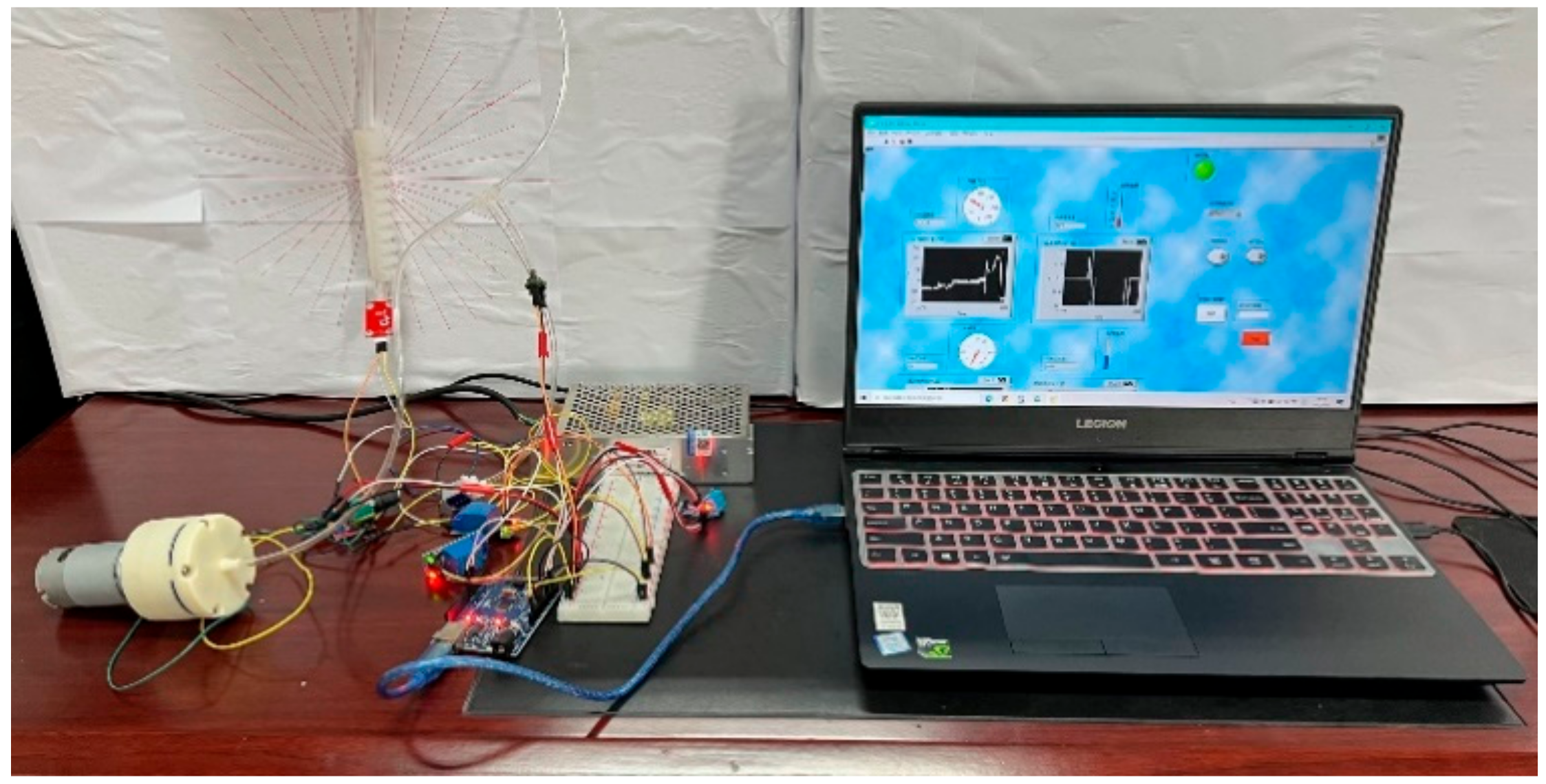
Finally, a variety of electronic equipment were applied to design a computer control system and build an experimental platform to test the actual operation performance of the soft gripper. The results show that the soft gripper can flexibly grasp and release objects of various shapes through the control system, and can detect real-time pressure, intensity of pressure, temperature, and humidity. Additionally, the loading capacities of the three-finger and four-finger soft grippers were quantitatively verified. Therefore, the soft gripper has industrial applicability in specific environments, especially in the screening and handling of vulnerable objects and precision instruments. Besides, it has special use in the detection of toxic and harmful scenes and the handling of dangerous bombs in the military field.
The research on this set of soft grippers provides valuable reference for facilitating the further processing of a lightweight and miniaturized gripper design.

Author Contributions

Formal analysis, P.F.; Investigation, J.L.; Project administration, Z.G.; Resources, T.J.; Software, W.Z. and L.D.; Writing—review & editing, J.L. All authors have read and agreed to the published version of the manuscript.

Funding

This research received no external funding.

Institutional Review Board Statement

Not applicable.

Conflicts of Interest

The authors declare no conflict of interest.

References

  1. Ilievski, F.; Mazzeo, A.D.; Shepherd, R.F.; Chen, X.; Whitesides, G.M. Soft Robotics for Chemists. Angew. Chem. Int. Ed. 2011, 50, 1890–1895. [Google Scholar] [CrossRef] [PubMed]
  2. Deimel, R.; Brock, O. A Novel Type of Compliant and Under actuated Robotic Hand for Dexterous Grasping. Int. J. Rob. Res. 2016, 35, 161–185. [Google Scholar] [CrossRef] [Green Version]
  3. Zhang, J.; Wang, T.; Hong, J.; Wang, M.Y. Review of Soft-bodied Manipulator. J. Mech. Eng. 2017, 7, 19–28. [Google Scholar] [CrossRef]
  4. Polygerinos, P.; Wang, Z.; Overvelde, J.T.B.; Galloway, K.C.; Wood, R.J.; Bertoldi, K.; Walsh, C.J. Modeling of Soft Fiber Reinforced Bending Actuators. IEEE Trans. Robot. 2015, 31, 778–789. [Google Scholar] [CrossRef] [Green Version]
  5. Wang, Z.; Polygerinos, P.; Overvelde, J.T.; Galloway, K.C.; Bertoldi, K.; Walsh, C.J. Interaction Forces of Soft Fiber Reinforced Bending Actuators. IEEE/ASME Trans. Mechatron. 2017, 22, 717–727. [Google Scholar] [CrossRef]
  6. Shepherd, R.F.; Ilievski, F.; Morin, S.A.; Stokesa, A.A.; Mazzeo, A.D.; Chen, X.; Wanga, M.; Whitesides, G.M. Multigait Soft Robot. Proc. Natl. Acad. Sci. USA 2011, 108, 20400–20403. [Google Scholar] [CrossRef] [PubMed] [Green Version]
  7. Polygerinos, P.; Wang, Z.; Galloway, K.C.; Wood, R.J.; Walsh, C.J. Soft Robotic Glove for Combined Assistance and At-home Rehabilitation. Rob. Auton. Syst. 2015, 73, 135–143. [Google Scholar] [CrossRef] [Green Version]
  8. Polygerinos, P.; Lyne, S.; Wang, Z.; Nicolini, L.F.; Mosadegh, B.; Whitesides, G.M.; Walsh, C.J. Towards a Soft Pneumatic Glove for Hand Rehabilitation. In Proceedings of the 2013 IEEE/RSJ International Conference on Intelligent Robots and Systems (IROS), Tokyo, Japan, 3–7 November 2013; pp. 1512–1517. [Google Scholar] [CrossRef]
  9. Li, Y.; Chen, Y.; Yang, Y.; Wei, Y. Passive Particle Jamming and Its Stiffening of Soft Robotic Grippers. IEEE Trans. Robot. 2017, 33, 446–455. [Google Scholar] [CrossRef]
  10. Song, S.H.; Ahn, S.H.; Park, C.H.; Son, Y.S. Design of Soft Actuator Using 3D-printed Composite. In Proceedings of the 2017 14th International Conference on Ubiquitous Robots and Ambient Intelligence (URAI), Jeju, Korea, 28 June–1 July 2017; pp. 79–80. [Google Scholar] [CrossRef]
  11. Mosadegh, B.; Polygerinos, P.; Keplinger, C.; Wennstedt, S.; Shepherd, R.F.; Gupta, U.; Shim, J.; Bertoldi, K.; Walsh, C.J.; Whitesides, G.M. Pneumatic Networks for Soft Robotics That Actuate Rapidly. Adv. Funct. Mater. 2014, 24, 2163–2170. [Google Scholar] [CrossRef]
  12. Shapiroa, Y.; Wolf, A.; Gabor, K. Bi-bellows: Pneumatic Bending Actuator. Sens. Actuators A Phys. 2011, 167, 484–494. [Google Scholar] [CrossRef]
  13. Wang, T.Y.; Ge, L.; Gu, G.Y. Programmable Design of Soft Pneu-net Actuators With Oblique Cavitys can Generate Coupled Bending and Twisting Motions. Sens. Actuators A Phys. 2018, 271, 131–138. [Google Scholar] [CrossRef]
  14. Wang, Z.K.; Zhu, M.Z.; Kawamura, S.; Hirai, S.C. Comparison of Different Soft Grippers for Lunch Box Packaging. Robot. Biomim. 2017, 4, 10. [Google Scholar] [CrossRef] [PubMed]
  15. Brown, E.; Rodenberg, N.; Amend, J.; Mozeika, A.; Steltzc, E.; Zakin, M.R.; Lipson, H.; Jaeger, H.M. Universal Robotic Gripper Based On the Jamming of Granular Material. Proc. Natl. Acad. Sci. USA 2010, 107, 18809–18814. [Google Scholar] [CrossRef] [Green Version]
  16. Li, H.L.; Yao, J.T.; Zhou, P.; Chen, X.B.; Xu, Y.D.; Zhao, Y.S. High-Load Soft Gripper Based on Bionic Winding Effect. Soft Robot. 2019, 6, 276–288. [Google Scholar] [CrossRef]
  17. Jiang, H.; Liu, X.H.; Chen, X.T.; Wang, Z.C.; Jin, Y.S.; Chen, X.P. Design and Simulation Analysis of a Soft Manipulator Based on Honeycomb Pneumatic Networks. In Proceedings of the 2016 IEEE International Conference on Robotics and Biomimetics (ROBIO), Qingdao, China, 3–7 December 2016; pp. 350–356. [Google Scholar] [CrossRef]
  18. Hao, Y.F.; Gong, Z.Y.; Xie, Z.X.; Guan, S.Y.; Yang, X.B.; Ren, Z.Y.; Wang, T.M.; Wen, L. Universal Soft Pneumatic Robotic Gripper with Variable Effective Length. In Proceedings of the 2016 35th Chinese Control Conference (CCC), Chengdu, China, 27–29 July 2016; Volume 8, pp. 6109–6114. [Google Scholar] [CrossRef]
  19. Renda, F.; Giorelli, M.; Calisti, M.; Cianchetti, M.; Laschi, C. Dynamic Model of a Multibending Soft Robot Arm Driven by Cables. IEEE Trans. Robot. 2014, 30, 1109–1122. [Google Scholar] [CrossRef]
  20. Kim, H.I.; Han, M.W.; Wang, W.; Song, S.H.; Rodrigue, H.; Ahn, S.H. Design and Development of Biome-Meticsoft Robotic Hand with Shape Memory Alloy. In Proceedings of the 2015 IEEE International Conference on Robotics and Biomimetics (ROBIO), Zhuhai, China, 6–9 December 2015; pp. 2330–2334. [Google Scholar] [CrossRef]
  21. Cao, Y.; Huang, J.; Ding, G.; Wang, Y. Design of nonlinear predictive control for pneumatic muscle actuator based on echo state Gaussian process. IFAC-PapersOn-Line 2017, 50, 1952–1957. [Google Scholar] [CrossRef]
  22. Chavoshian, M.; Taghizadeh, M.; Mazare, M. Hybrid Dynamic Neural Network and PID Control of Pneumatic Artificial Muscle Using the PSO Algorithm. Int. J. Autom. Comput. 2020, 17, 428–438. [Google Scholar] [CrossRef]
  23. Wang, H.S.; Chen, W.D.; Yu, X.J.; Deng, T.; Wang, X.Z.; Pfeifer, R. Visual Servo Control of Cable- driven Soft Robotic Manipulator. In Proceedings of the 2013 IEEE/RSJ International Conference on Intelligent Robots and Systems (IROS), Tokyo, Japan, 3–7 November 2013. [Google Scholar] [CrossRef]
  24. Sun, Z.S.; Guo, Z.H.; Tang, W. Design of Wearable Hand Rehabilitation Glove with Soft Hoop-Reinforced Pneumatic Actuator. J. Cent. South Univ. 2019, 26, 106–119. [Google Scholar] [CrossRef]
Figure 1. Casting molding process diagram.
Applsci 12 06306 g001
Figure 2. The pneumatic soft gripper.
Applsci 12 06306 g002
Figure 3. Structure diagram of pneumatic gripper fixture.
Applsci 12 06306 g003
Figure 4. Bending deformation of actuator.
Applsci 12 06306 g004
Figure 5. Soft bending actuator trajectory for bending angle from 0 kPa to 70 kPa.
Applsci 12 06306 g005
Figure 6. Diagram of increasing pressure drum in soft actuator.
Applsci 12 06306 g006
Figure 7. Effect of cavity wall thickness on bending angle.
Applsci 12 06306 g007
Figure 8. Effect of cavity height on bending angle.
Applsci 12 06306 g008
Figure 9. Effect of cavity spacing on bending angle.
Applsci 12 06306 g009
Figure 10. Effect of cavity number on bending angle.
Applsci 12 06306 g010
Figure 11. Simulation diagram of the bottom bulge of the soft actuator.
Applsci 12 06306 g011
Figure 12. Effect of cavity-limiting layer thickness on bending angle.
Applsci 12 06306 g012
Figure 13. Soft gripper grasping apple diagram.
Applsci 12 06306 g013
Figure 14. The control system of soft gripper.
Applsci 12 06306 g014
Figure 15. Air tightness check of soft actuator.
Applsci 12 06306 g015
Figure 16. Experiment on the field test diagram of soft gripper.
Applsci 12 06306 g016
Figure 17. Comparison of theoretical calculation, simulation calculation, and experimental results.
Applsci 12 06306 g017
Figure 18. The relationship diagram between air pressure and grasping object mass.
Applsci 12 06306 g018
Figure 19. Test on the maximum grasped weight of the soft gripper.
Applsci 12 06306 g019
Figure 20. The schematic of soft gripper grasping different object (a) mineral water bottle; (b) remote controller; (c) napkin paper; (d) Bar bread; (e) needle tube; (f) cola-bottle; (g) oriange; (h) egg.
Applsci 12 06306 g020
Table 1. Geometric parameters of actuator.
Size ParametersValue (mm)
Length of the soft actuator (L/mm)85
Height of the soft actuator (H/mm)10
Height of the air cavity (w/mm)2
Outer width of the air cavity (w/mm)10
Inner width of the air cavities (d/mm)
Limiting layer thickness
6
1.5
Base thickness (t/mm)2
arc radius (r/mm)3
Air pressure (kPa)0–65
Actuators materialsDragion 30, E610
Table 2. Determination of airtightness of soft fingers.
NumberTimes
1210
2230
3197
4242
5199
Publisher’s Note: MDPI stays neutral with regard to jurisdictional claims in published maps and institutional affiliations.

