Review

Finite Element Methods for Modeling the Pressure Distribution in Human Body–Seat Interactions: A Systematic Review

Department of Aerospace Engineering, Toronto Metropolitan University, Toronto, ON M5B 2K3, Canada
*
Author to whom correspondence should be addressed.
Appl. Sci. 2022, 12(12), 6160; https://doi.org/10.3390/app12126160
Submission received: 6 June 2022 / Revised: 13 June 2022 / Accepted: 13 June 2022 / Published: 17 June 2022

Abstract

:
The objective of this systematic review is to investigate the various approaches that have been undertaken in finite element analysis (FEA) of human–seat interactions and synthesize the existing knowledge. With advances in numerical simulation and digital human modeling, FEA has emerged as a powerful tool to study seating comfort and discomfort. FEA employs various biomechanical factors to predict the contact stress and pressure distribution in a particular seat design. Given the complexity of human–seat interaction, several modeling and processing steps are required to conduct realistic FEA. The steps of how to perform an FEA simulation on human–seat interactions, the different models used, the model mesh compositions, and the material properties are discussed and reviewed in this paper. This can be used as a guideline for future studies in the context of FEA of human–seat interactions.

1. Introduction

In today’s world, we spend most of our time sitting or lying down, whether it is at work behind a desk, at home watching TV, sleeping at night or in hospital beds, or even while travelling by car or plane. It is well known that uncomfortable sitting positions can cause extreme discomfort and health disorders, such as neck and back pain and pressure ulcers [1]. Therefore, improved seating and sleeping comfort is an important component that many manufacturers consider. Modeling comfort is important as it simulates the human body–seat or body–bed interaction and provides data that can help optimize designs [2]. In the aerospace and automotive industry, many companies focus on seating comfort to distinguish themselves from their competitors. In the health industry, hospital beds and wheelchairs are being improved to reduce the risks of injuries such as pressure ulcers that result from being immobile for a long period of time.
There are different approaches to simulating the interaction between humans and seats/beds [3,4], such as conducting experimental tests using different subjects and pressure maps, which provide the pressure distribution applied to the seat by the human, where the pressure distribution can be used to design a more comfortable seat/bed [2,5]. However, this approach has several limitations because a designed prototype should be available to run the experimental tests; if the prototype is not considered to be comfortable, another prototype should be designed and tested, which is expensive and inefficient. In addition, gathering data about comfort, such as contact stress, is challenging due to the complexity of the human body, and the different layers it is composed of. Therefore, the other approach, which is the focus of this paper, is finite element analysis (FEA) of human–seat interactions. FEA is a computerized method for predicting how a structure reacts to real-world forces and physical effects [6]. For human body–seat/bed interactions, the human body and the seat/bed are discretized into elements and then certain boundary conditions are applied. Finally, the results show the contact stress and pressure distribution between the human and the object, which represents the (dis)comfort and points of maximum stress that can generate pressure ulcers. Although the FEM method has great potential in providing a means for computationally simulating real-world physical interaction between a human body and seat/bed, the computational cost of performing the matrix inversions on very fine and complex mesh structures is quite high. For this reason, another approach is to parameterize the seat/bed design for comfort by focusing on the pressure distribution as it is considered to have the clearest association with seat/bed comfort, and thus, parameters relating to the pressure distribution, such as peak pressure and contact area, have been used as indications of the comfort level of a seat/bed. The use of multibody biomechanical modeling and contact mechanics is considered to be a faster method than FEM for simulating the human body and seat/bed pressure distribution.
Despite the recent advances in finite element methods, FEA of human–seat interactions remains challenging. This stems from the many complicated steps that need to be taken to appropriately model the geometrical and material properties of the different layers of the human body, e.g., skeletons, muscles, and skin. Once a suitable human model is obtained, appropriate modeling of the human–seat contact, representation of the boundary conditions, and experimental validation of the FEA results need to be addressed. To the authors’ best knowledge, the existing commercial software do not offer a validated human–seat model. A few finite element models, such as THUMS [7], GHMBC [8], and PIPER [9], have been recently developed to study crash safety in the automotive industry. There are several other models presented in the literature for comfort/discomfort and pressure ulcer studies. However, there is no consensus on the level of detail, the different layers of the human body to be modeled, and the material properties of each layer. Moreover, the advantages and disadvantages of the different existing methods are not clear. One review paper [10] reviewed the different approaches used for FEA of human–seat interactions, but it was limited to pressure ulcer studies on the buttock and thigh area. Full-body studies, especially the important topic of backrest comfort, and a comparison of the different methods and their advantages and disadvantages have not been discussed.
To address the above gap, the current study aimed to conduct a systematic review of the existing literature on FEA of human–body seat interactions to synthesize the existing knowledge on this topic. We investigated what are main steps involved in FEA of human body–seat interactions to predict the static pressure distribution, and what are the different methods that have been used to approach each one of these steps? By answering these questions via a systematic review, we generated a set of recommendations for conducting similar studies in the future. We also present possible future research directions.
This paper is organized as follows: Section 2 describes the methodology used to conduct the systematic review. Section 3 explains our findings from the literature review. It includes identification of the main steps involved in conducting FEA of human–body seat interactions, and a summary of the different methods presented for each step. Section 4 discusses our findings, generating guidelines and future research directions. Section 5 presents the concluding remarks.

2. Methods

2.1. Literature Search Strategy

A comprehensive electronic database search was performed to find papers that used finite element analysis on human seat–bed interactions. The search covered a period from 2000 to December 2021 and included Engineering Village, which combines 12 databases: Ei Compendex, Inspec—IET, GEOBASE, GeoRef—AGI, US Patent—USPTO & EU Patents—EPO, NTIS, EnCompassLIT & EnCompassPAT, Paperchem, CBNB, and Chimica, plus SCOPUS. All these databases were chosen for their inclusiveness in the scientific and engineering fields. The search strategy used key words pertaining to FEA of human seat–bed interactions, including: finite element model, finite element analysis, FEA, FEM, seat optimization, modeling, seat model, seat cushion, human model, musculoskeletal model, human FE model, human finite element model, passenger aircraft seat, car seat model, human 3D model, human–seat model, comfort, discomfort, and ergonomics. To ensure comprehensive coverage of the literature, we also studied the references contained within the papers identified in the search results and the papers that cited those papers that appeared in the search.

2.2. Study Selection

The inclusion criteria were: (i) English language papers, (ii) FEA on human interactions in seat and bed designs, (iii) FE human models, (iv) seated models, (v) pressure ulcer studies, and (vi) soft tissue modeling. The exclusion criteria were: (i) studies that focused on the use of FEA in the structural design of seats and beds, (ii) papers that do not have human models, (iii) the absence of finite element analysis, (iv) studies that were not related to seat/bed design, and (v) the use of FEA that was not related to human–seat interactions.

2.3. Data Extraction
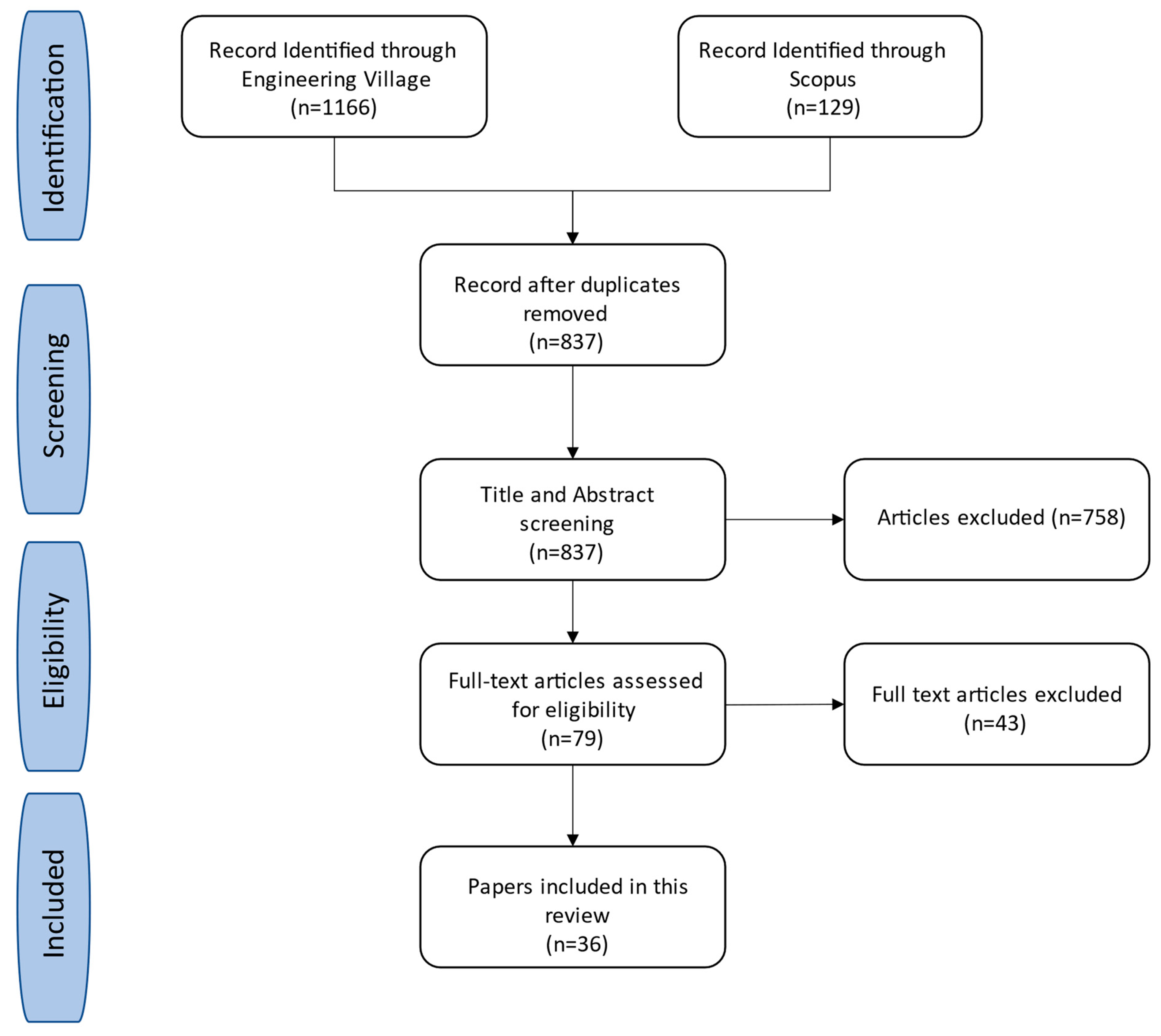
The main information extracted focused on the study population and study purpose. The former included the population studied, seat modeling, geometry composition, geometry source, body region, material modeling, mesh type, mesh size, simulation approach, boundary conditions, and validation process. The latter covered FEA for comfort analysis and for pressure ulcer detection. Through discussion, the selected papers were categorized based on their approach to FEA of human–seat interactions.

3. Results

3.1. Search Results

The database search for studies published in English since 2000 yielded a total of 1166 papers from Engineering Village, and 129 papers from Scopus. After removing 458 duplicates, the titles and abstracts of papers were screened, which resulted in 79 papers for full-text assessment. These papers were then reviewed to determine whether they met the inclusion or exclusion criteria. Finally, a total of 36 papers met the inclusion criteria and thus were included in the data extraction and analysis. Figure 1 illustrates the flow of the study selection process.

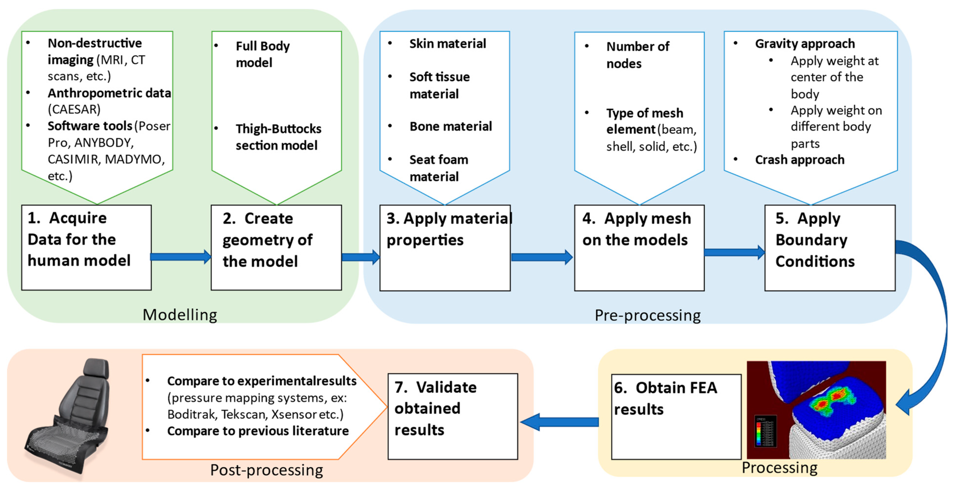
3.2. Main Steps in FEA of Human–Seat Interactions

From the 36 papers selected, we found that FEA has been applied to the entire system, which starts with the outer layer of the human model, the skin, and then the soft tissue, the bone structures, and, finally, the seat.
The steps needed for this simulation are:
(1)
Acquiring data to build the proper geometry;
(2)
Creating the geometry of the model;
(3)
Applying material properties to different sections of the model;
(4)
Applying mesh elements on the different sections of the model;
(5)
Applying boundary conditions;
(6)
Processing the simulation to obtain results; and
(7)
Validating the obtained results.
Figure 2 illustrates the flow of the steps required, and the variety of options that the literature has used in each step. The rest of this section explains each of the above steps in detail.

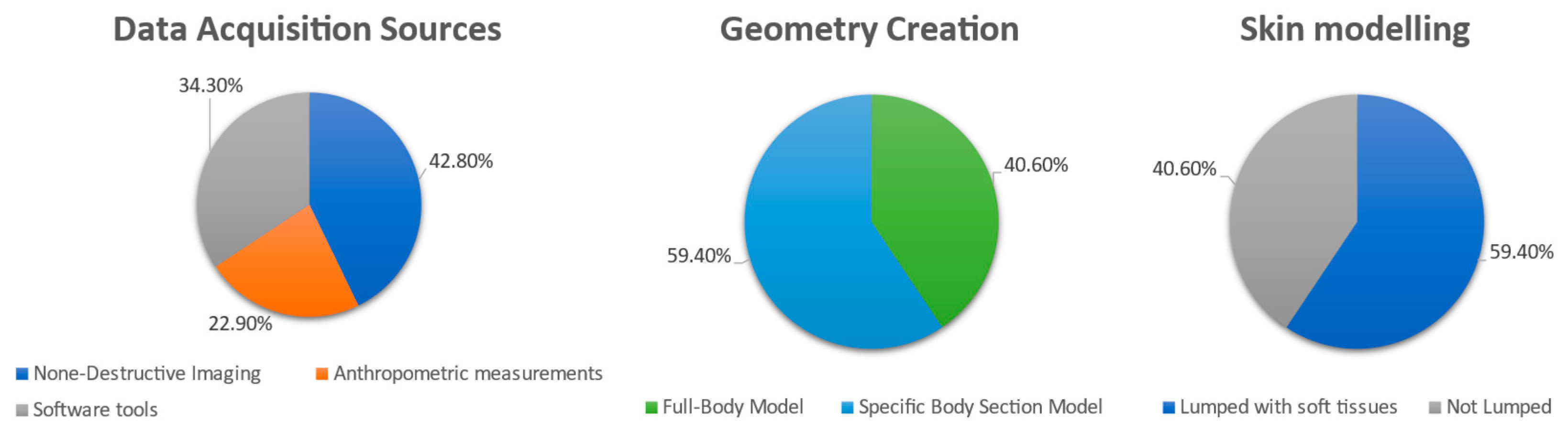
3.2.1. Model Data Acquisition

Generally, the methods used for model acquisition in the literature can be categorized into three groups: (1) non-destructive imaging techniques such as magnetic resonance imaging (MRI) scans, computed tomography (CT) scans, and 3D laser scans; (2) anthropometric measurements; and (3) various software tools. MRI scans are used when the inclusion of specific organs or the accuracy of the results is important. CT scans are another data source used for accurate models. Three-dimensional scans are used when the important geometry is the outer shape of the subject. Another source of data is anthropometric resources, which are the measurements of different percentiles within a population and are obtained from different databases that are available online. A popular site is the Civilian American and European Surface Anthropometry Resource (CAESAR) database [11], which contains the anthropometric variability of men and women, aged 18–65 years, covering various weights, ethnic groups, genders, geographic regions, and socio-economic statuses. Finally, the last category of geometry sources includes software such as: (1) POSER Pro [12], (2) MADYMO [13], (3) ANYBODY [14], and (4) CASIMIR [15]. POSER [12] is a 3D computer graphics program and provides optimized 3D modeling of human figures. MADYMO [13] is a standard software used for analyzing and optimizing vehicle safety designs and consists of a unique combination of multibody, finite elements, and computational fluid dynamics technologies. This software focuses on vehicle occupants with a variety of human body models. ANYBODY [14] is a software package that simulates the human body’s interaction with its environment using various musculoskeletal models and provides force and motion simulation data. CASIMIR [15] is a computer-aided engineering solution for the simulation of static and dynamic seating comfort.
A few papers [16,17,18,19,20,21] have used multiple sources to create a human model for simulation. Bones are either obtained from MRI or CT scans [2,18,19,20,22,23,24,25,26] whereas skin is obtained from CT scans or 3D laser scans [17,21,22,27,28]. Since MRI scans are usually performed in a lying-down position, an additional step of modifying the model is required to convert the posture to a seated position, which could alter the accuracy of the models, especially the soft tissue as it would differ in form and size. Other papers [2,19,28] have used scans from a seated position. A 50th percentile male model is the most used model in different papers [1,2,15,16,17,18,21,23,26,27,28,29,30,31,32,33,34,35,36,37,38,39] as it is considered to be the average human being. A few papers [19,34,38] have used a 95th percentile male model, and one paper [39] used an 80th percentile male model.

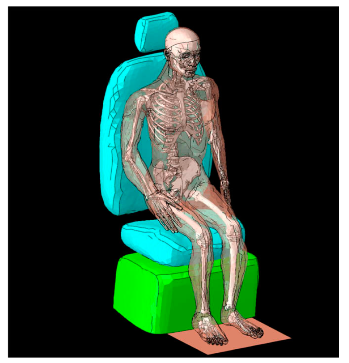
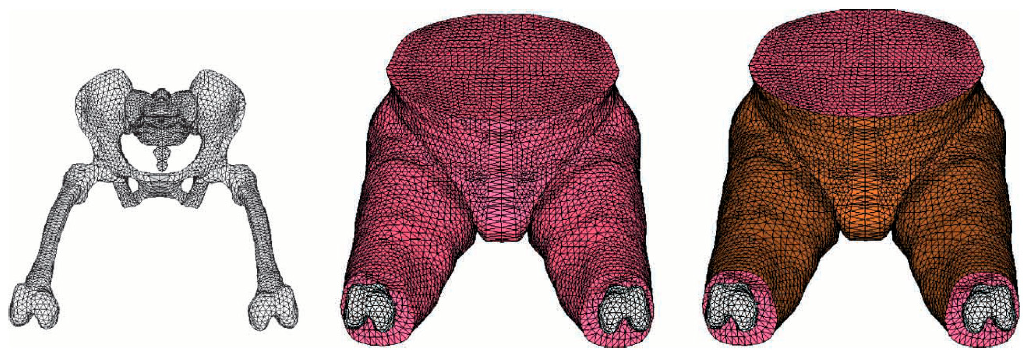
3.2.2. Body Geometry

After gathering data using the various data acquisition methods stated in the previous section, generating the body geometry is the next step. Papers studied for this review have been divided into two categories. The first category includes papers that used a full-body geometry model [1,2,16,17,28,29,30,33,34,35,40], and the second category includes the ones that used a specific section of the body [15,19,21,23,24,25,27,31,32,36,37,38,39,41,42,43,44]. Within those groups, there are models that include mechanical properties [15,19,21,23,24,25,27,32,36,37,38,39,42,43,44], and they are also divided into anatomical [15,21,23,24,25,38,39,42,43,44] and phenomenological setups [19,27,29,35,40]. Anatomical models represent a human model based on its physiological characteristics, where the details of certain body parts such as organs and specific bone structures are portrayed. On the other hand, phenomenological human models are used to show a single characteristic, such as the pressure distribution, of the subject being studied. Depending on the type of results needed, the models can describe a specific part or the entire body.
Full-body geometry, as shown in Figure 3, consists of a skeletal model that shows the pelvis, femur, tibia, cervical, spine, and the head, and a detailed soft tissue model contains the muscles, ligaments, fat, and skin. Nevertheless, not all full-body models contain this level of detail. Three papers have used a full-body model that consists of a volumetric model that mimics the outer shape of the human body without representing the anatomical parts [2,31,40]. This is because the authors in the studies have only investigated a certain behavior such as the pressure distribution of the model interacting with a seat or other padded furniture.
On the other hand, there are papers that have focused on a certain body section such as the thigh and buttocks section as seen in Figure 4, where the focus was on studying the stress and strain contact forces between the human and the seat pan for comfort and discomfort analysis [1,15,16,17,18,19,21,23,24,25,27,31,32,33,36,37,38,39,41,42,43,44]. The level of detail included accurate models of the iliac wings, sacrum, coccyx femora, soft tissues, and skin. Another use of accurate thigh and buttocks models is the study of the internal stress on the ischial tuberosities in the development of pressure ulcers [20,23,25,26,32,45].

3.2.3. Material Properties

The next step in conducting an FEA simulation of human body–seat interactions is assigning the material properties for each of the models obtained or created in the previous step. Many papers have used similar material models. The human body has no specific material in the FE software database that can be assigned. For example, there is no material called bones, muscles, or skin in the database; therefore, a material property that mimics the behavior of the specific body part should be assigned, and that material could change based on the human subject being studied.

Skin Material Properties

Starting from the external layer of the human body, there is the skin, which has an elasticity behavior. Several papers [18,23,24,37,41,42,44,46] chose to ignore the skin since it has a negligible effect on the results. Nonetheless, other papers decided to lump the skin with the soft tissue material and model it as a soft tissue [2,17,20,21,25,27,31,35,38,40,43], which is discussed in the next section. Papers that assigned a material for the skin [1,16,30,32,47] used a linear isotropic elastic material with an elasticity of 0.15 MPa.

Soft Tissue Material Properties

The second human body layer is the soft tissue, which includes the muscles, fat tissue, tendinous structures, and blood vessels. Blood, interstitial lymph, and fluid surround these tissues [46]. Thus, biological tissues are nonlinear, anisotropic, and viscoelastic. Many finite element models have been developed to simulate the soft human tissues, and various approaches have been observed from the papers read for this review paper. Several authors have used a single model to describe the behavior of all the components [1,2,17,18,19,21,23,24,25,26,27,28,29,32,37,39,40,42,44]; however, other papers have used mathematical models for tendinous structures, and muscular tissue and a changed one for fat [15,16,30,31,33,34,35,36,38,41,43]. However, there are a few models that have been used by many papers because of the accuracy of the results that they portray. These models include: (1) Todd and Thacker [47], which models all tissues by considering a single linear elastic, isotropic, and equivalent material simultaneously; (2) Deng and Hubbard [48], which models all the tissues at once by using a single hyperelastic equivalent material, such as the neo-Hookean formulation; (3) Dabnichki et al. [45], on the other hand, uses a single hyperelastic Mooney–Rivlin formulation that models the tissues simultaneously; and (4) Verver [44], which is the most common method used by many papers [1,16,17,18,20,21,26,28,29,39,40,42], which also uses a single hyperelastic equivalent material Mooney–Rivlin formulation to model the soft tissues; however, the skin is not included in this formulation, and hence a linear elastic isotropic material is used for the skin.
There are different hyperelastic models that can be used for soft tissue modeling. The neo-Hookean model is a model similar to Hooke’s law that is used for materials that undergo large deformation by predicting the stress–strain behavior of these materials. The neo-Hookean model [19] is a very simple hyperelastic model that consists of one material parameter only, which is the initial shear modulus. The stress–strain of the model is linear until it reaches a certain point, where the curve becomes non-linear [49]. The strain energy density function of a non-compressible neo-Hookean model contains a material constant and a Cauchy–Green deformation tensor [49]. This model does not provide accurate prediction at large strains, and the use of this model is good if the results that are being assessed are focused on the pressure distribution rather than the stress values at specific locations [19]. On the other hand, another model is the Mooney–Rivlin model [1,16,17,18,20,26,28,29,40,42,44], which generalizes the hyperelastic model of the neo-Hookean model. The strain energy density function of the Mooney–Rivlin model is a linear combination of the Cauchy–Green deformation tensor and an incompressible Mooney–Rivlin material. It consists of two empirically determined material constants. In addition, the material constants of the model are related to the linear elastic shear modulus. The Mooney–Rivlin model shows good agreement with tensile data of up to 100% strain and is mostly used to model biological tissues [1]. Finally, the third model is the Ogden material model [24,25,45], which is a hyperelastic material model that is used to model the non-linear stress–strain behavior of complex materials. Similar to the previous two models, the Ogden model uses a strain energy density function to derive the stress–strain behavior of materials that are isotropic, incompressible, and independent of the strain rate. The Ogden model is the most used model for the analysis of rubber components, cushion foam, and biological tissues, and it is different than the Mooney–Rivlin and neo-Hookean models as it is not expressed by a Cauchy deformation tensor. All the hyperelastic material models consist of a different N order of the functions, and the order is usually decided based on the desired accuracy of the results and the behavior of the material that is being mimicked.

Bone Material Properties

The next body part is the boney skeletal section, which in the case of a full-body model consists of the spine, pelvis, femur, tibia, cervical, head, and arms. In the case of the thigh and buttock model, which has been studied in some papers [15,19,23,24,25,27,31,32,36,37,38,41,42,43,44], it consists of the thigh bones, pelvis, and sometimes the lumbar spine section. The material chosen to represent the bones section of the model is a rigid material with a Young’s modulus between 10,000 and 12,000 MPa, a density of 1100 to 1700 kg/m3, and a Poisson’s ratio of 0.3. In cases where the focus is on pressure ulcers, the ischial tuberosity is an important factor in the simulation as it is the main cause of pressure ulcers in situations where the human is sitting for a long period of time. The parts of the skeletal structure that contribute to pressure ulcers have different values, where the lower limb bone and pelvic bone have an elasticity modulus of 180,000 MPa, density of 6000 kg/m3, and a Poisson’s ratio of 0.3. However, one of the papers reviewed focused on pressure ulcers in the head section [20]. In this case, the skull was modeled as an isotropic, linearly elastic material with a modulus of elasticity of 6848 MPa and a Poisson’s ratio of 0.2.

Seat Foam Material Properties

For seating comfort, a seat model is used for the analysis. The material models used for seats are the same as the soft tissue material, which has a hyperelastic material property because it mimics the nonlinear behavior of the polyurethane foam used for seats. The parameters are chosen based on the material properties provided by the seat manufacturers or from the use of indentation tests that show the stress–strain curve. In five papers, the seat was modeled as a rigid body for the sake of simplicity to focus on the testing of different human models [18,23,31,36,45].

3.2.4. Meshing

After data acquisition, model generation, and material modeling, the next step in FEA simulations is to create the meshing. This is the process of discretizing the models into finite elements to create a solution [1] that represents the interaction between the human and the seat. Many types of elements can be used, such as beam, shell, and solid elements, and they are used based on the complexity of the geometrical model and the desired accuracy of the results. The higher the number of nodes the element contains, the higher the accuracy is.
A four-node tetrahedron element is the type that is selected the most [1,16,18,24,26,29,36,41,42,44,47] among the papers reviewed, and it can be concluded that the choice of this type is due to the desired accuracy of the results. Therefore, the papers that selected the four-node tetrahedron element and applied it to geometrical models contribute the most to the solution, such as soft tissues and seat foam sections, as they are in direct contact with each other and cause contact stress, which affect the pressure distribution results needed as a measure of comfort; however, in cases where the focus of the research was on pressure ulcers, more complex types have been used, such as 8-node and 10-node hexahedron elements. The element size used in four papers [17,31,43,47] was 10 mm, and in one paper [18], it was 20 mm. Two papers mentioned mesh convergence analysis being undertaken [1,42], with one of them [42] stating that they were able to reduce the element size to as low as 9 mm during their convergence analysis; however, due to a limitation on computing power, they could not further refine the mesh to an 8 mm element size. The total number of elements in most of the papers was between 150,000 and 460,000 elements.

3.2.5. Boundary Conditions

Before finally performing the simulation, the boundary conditions should be applied, based on the forces that are applied to each of the models. Different types of approaches have been used in seat comfort papers. The first and most used approach is the gravity approach [1,2,15,16,17,18,19,20,23,25,26,28,29,30,32,33,34,35,36,39,44,50], where the human model is in contact with the seat and the weight of the human is applied constantly over time at the center of the model as a gravity force pointing downwards towards the seat; however, in other cases [24,26,29], where the model used is a thigh and buttock model, the weight is distributed over the different parts of the body, where 55% of the total body weight is split between the two ischial tuberosities, 27% is split between each femur, and 18% of the body weight is split between the centers of mass of each lower leg. In addition, when the focus is on pressure ulcers, the most important part is the ischial tuberosities (ITs). In such cases [23,24], 60% of the body load is applied on each of the ITs. The next boundary condition to be applied is the constraint on any unwanted movement of parts, so papers that focused on seating comfort needed the results to show the pressure distribution on the seat after a certain period of time. Therefore, the body was constrained from moving in any direction other than the z direction, the same direction as gravity. The next constraint applied is the contact constraint. For the purpose of comfort analysis and pressure ulcers, the method used is a penalty based on surface-to-surface contact as the model, which is a time-domain model. For the gravity approach, the contact constraint is the penalty-based method, where the two touching surfaces are identified, and one is set as a master surface, the human surface, and the other is the slave surface, which is the seat cushion. Finally, the friction coefficient is assigned. This varies depending on the type of seat used; however, it is usually between 0.2 and 0.4. Two papers have used a different approach [29,37] to the boundary conditions, which is the crash approach. This approach is similar to the gravity approach but has a different placement of the body, where the human body is placed 0.1 to 1 mm on top of the seat and is allowed to be dropped in the z direction towards the seat and the results are obtained after the simulation is completed. One of the pressure ulcer papers [50] used an approach that is different from the other known methods, where a downward displacement of 14.6 mm was applied to the IT. Researchers chose the boundary conditions based on the conditions that are present during the research.

3.2.6. Initial Condition

For the finite element simulation of a human body seat–bed interaction, the second derivative of time is a necessary term in the governing equations to describe acceleration and thus necessitates a definition of the initial conditions, which describe the bodies’ displacement and velocity at t = 0. While a number of the reviewed papers did not mention the initial condition settings [2,10,21,24,27,30,34,41,43,45], the papers that did generally placed the body above the cushion with a small interspace gap (up to 10 mm) without any penetration of the meshes during contact. Most of the papers set the initial velocity of the human body to 0 m/s and gravity was the only body force that loaded the human body on the seat/bed under slave/master quasi-static conditions. One exception is [28], which used an initial velocity of 0.1 m/s as the focus of this paper was directed towards the backrest instead of the seat pan and so the authors implemented a slightly different initial condition setting than most of the other papers. Detailed information about the initial conditions is given in Appendix B.

3.2.7. Validation

To validate the results, the method used by most of the papers [17,18,20,24,25,26,27,29,31,33,35,36,37,39,40,43,44] is a comparison of the simulation results with the experimental results. The other method used by some papers [1,2,16,19,21,23,30,31,38,41,44] is a comparison of the results from the open literature. The experimental method involves a volunteer with similar characteristics to the population in the study, who is seated on a seat that is fitted with a pressure mapping system. The force-sensitive applications (FSAs) pressure mapping system now known as BoditTrak [51] was used by many papers [17,27,29,40,42,43,46], which included 16 × 16 sensors, with a sensor size of 26.875 mm, a sample rate of 3072 sensors/s, calibrated pressure range between 0 and 200 mmHg, and an allowable stress of 26.7 kPa. Other pressure distribution measurement systems used were Tekscan [52], and Xsensor technology [53], which work similarly to the FSA pressure mapping system. The choice of using an experimental validation method or an open literature comparison method depends on the available resources and the overall environment of the test.
The results from the experimental testing and the simulations show a good correlation with low percent errors, ranging from 2% to 9% error. It was noted that the papers that used a finer mesh with a high number of elements had a lower percentage of error, such as Ile merchant et al. [39], where the element size was low and the element type was a 4 node tetrahedron element, which had a percent error of 2 when compared to Verver et al. [44] for validation. However, in the case of Yary Volpe et al. [37], where the number of elements was lower, a percentage of error of 9% was noted, which was acceptable for the purpose of this study.

4. Discussions and Recommendations

The objective of this study was to consolidate the existing knowledge and methods pertaining to FEA on human body–seat interactions for seat or bed design. Section 3 outlines the steps and various methods used during each stage of the simulation. A comparative understanding of the different methods utilized is of great importance and facilitates the opportunity to create guidelines for future research in the field. Additionally, it must be noted that the observed differences between methodologies are due to the different resources, research purposes, and desired accuracy levels.
First, the acquisition of the required data for generating the geometry model varies significantly from one paper to another. The use of different data sources is based on the required accuracy of the models. If differentiation between muscles, fat, and skin is desired, medical imaging techniques should be used; otherwise, the use of anthropometric data is a simpler and cost-effective solution. The findings revealed that detailed models are mainly needed in the evaluation of pressure ulcers and other clinical applications. The studies concerned with automotive and seat manufacturing applications (focused on comfort) used models without a detailed representation of the soft tissues. While most papers used MRI data [18,19,23,24,25,26,50] as their main data source, other papers have used geometric databases [16,17,19,21,27,28,31,32,36,37,38,39,41,43], such as POSER, 3dcadbrowser, and Human builder, or software that contains human body geometries [1,15,29,30,33,35,44], such as ANYBODY, CASIMIR, and MADYMO, which use MRI scans as the main data source and provide accurate models for different kinds of simulation. The choice of the population percentile to be used for the study depends on the availability of subjects for the simulation and the purpose of the simulation. The use of models from full-body model software is the fastest and most validated method because it has been refined iteratively over years and improved through different versions. The THUMS [7] model created by Toyota has been made available to research institutions and can be used for the purpose of seat design. Figure 5 (left) shows the most commonly chosen methodology for acquiring data.
After acquiring the model data, the next step is creating the model geometry. Figure 5 (middle) shows the percentage of papers that chose to conduct their research by modeling specific sections of the body or using the full-body geometry. The full-body geometry composition, as shown in Figure 3, is used when different sections of the human body are being studied: specifically, the interaction between the seat pan and the human buttocks section and the interaction between the human back and the seat back rest [1]. However, the level of detail of the model depends on the desired accuracy of the simulation. Modeling of specific parts of the body has many advantages, such as time efficiency when constructing models and more accurate results when specific problems are tackled. For example, if the focus in the design of a seat is to make the seat pan more comfortable, the use of a thigh and buttocks section model is appropriate. Alternatively, if the focus of the seat design is to create a seat that is optimized for comfort in general, then the use of a full-body model is a better choice as it provides meaningful results regarding the interaction of the seat pan and seat back rest with the buttocks and back. It is recommended that a simulation is performed that combines skin with soft tissue to obtain time efficiency, instead of having them separated. As shown in Figure 5 (right), combining the skin with the soft tissues is the most common method used. The non-combined choice is more practical when investigating pressure ulcers as it provides better insight into the creation of ulcers in a specific area.
There are many differences between the methods utilized in papers regarding the application of material properties if different options are being explored. Starting with the skin section of the body, the use of a linear isotropic elastic material property with an elasticity of 0.15 MPa is appropriate when the skin is not combined with the soft tissues. The next layer is the soft tissues, which includes the muscles, ligaments, and fat. As portrayed in Figure 6, the use of a hyperelastic material property to model the soft tissues is the most used method; however, the choice of which hyperelastic model to use varies depending on the model created in the previous step. When the skin is combined with soft tissues, then Dabnichki et al.’s [45] Mooney–Rivlin hyperelastic material modeling is suitable. If the skin is modeled separately, then Verver et al.’s [44] Mooney–Rivlin hyperelastic material modeling should be utilized. The neo-Hookean model used by Todd and Thacker et al. [47] does not provide accurate prediction at large strains, which is ideal when the results that are being looked at are focused on the pressure distribution rather than the stress values at specific locations [19]. Finally, the Ogden model is best for use in the analysis of the rubber-like components of soft tissues. The bone layer is modeled as a rigid material with a Young’s modulus between 10,000 and 12,000 MPa, a density of 1100 to 1700 kg/m3, and a Poisson’s ratio of 0.3. In the case of pressure ulcer studies, the parts that affect the generation of pressure ulcers are modeled using a Young’s modulus of 180,000 MPa, a density of 6000 kg/m3, and a Poisson’s ratio of 0.3. Similar to soft tissue material modeling, hyperelastic models can be used in seat material modeling. However, the type of foam used in the design dictates which model is appropriate regarding implementation.
When meshing the geometry, four-node tetrahedron elements yield the most accurate results when compared to other meshes. Consequentially, the papers that selected a four-node tetrahedron element and applied it to geometrical models contributed the most to the solution, such as soft tissues and seat foam sections, as they are in direct contact with each other and cause contact stress that affects the pressure distribution results needed as a measure of comfort. In the pressure ulcer research cases, a more complex type should be used, such as 8-node and 10-node hexahedron elements. In conclusion, the selection of mesh element types is based on the trade-off between the efficiency and accuracy of the results because the more detailed the element is, the more time consuming the simulation; this decision is usually made based on the available resources.
The final step before processing the results is the application of boundary conditions. The gravity approach is the most common approach used by researchers, as it provides the advantage of being realistic when seating simulations are being conducted. However, in the case of pressure ulcer studies, the gravity approach is applied differently. Here, to obtain more accurate results, the body weight is divided among the body parts.

Future Research Directions

This review paper covers the methodologies used to perform FEA simulations for seat comfort and pressure ulcer determination. These simulations provide insight into the external forces acting on the human body while also providing the designer of seats/beds with the capability to include multiple computer-simulated design configurations in their design methodology and to compare the results of different design configurations to find the optimal design across different prototypes, such as motorcycle saddles, furniture, automotive seats, and hospital beds. The results are more useful if more information is provided, such as the internal force determination. In the future, the external forces from the FEA methodologies presented in this paper can be combined with the internal forces acting in the human body at the soft tissue and muscle level to provide a clearer image of comfort/discomfort to effectively optimize the design of seats and beds and reduce the risk of pressure ulcers and musculoskeletal injuries associated with prolonged static posture in the automotive and aviation industries [32]. Further simulations can help improve seat designs for seat manufacturers and improve bed designs for hospitals.
Internal forces can be obtained from software such as OpenSim [54] and Anybody [55], which provide musculoskeletal models that simulate the human body’s interaction with the environment to help quantify the forces and motions inside the body. OpenSim is an open-source software with a large library of models, including a full-body model and different sections of the body based on the research purpose. The models have been validated in research [54,56], making them ideal for integration in FEA studies of human–seat interactions, having outputs such as the pressure distribution of FEA as input in the biomechanical software, mentioned above, to further investigate comfort at a deeper level than the internal forces results.

5. Conclusions

This study examined papers that investigated the use of finite element methods for the modeling of human–seat interactions. Of the 36 papers found, the most common application goals were pressure ulcer prevention in healthcare settings and comfort and safety improvement in the automotive and seat-manufacturing industries. Extraction of the approaches used in these papers for both building finite element models and running finite element analysis showed a wide range of modeling methods and large variation in the target accuracy and fidelity of the models. By studying and categorizing these methods and their characteristics, this paper presented a general guideline for building an end-to-end study of FEA of human–seat interactions, including recommendations for the target level of the modeling fidelity depending on the application, the choice of the number of layers in finite element models, and their geometrical and material properties, etc. Although several models of the human body have recently become available to the public, and open-source software tools such as OpenSim exist for the study of internal forces, these tools are yet to be fully explored, especially for comfort design purposes. A clear need for future work on the integration of internal force analysis with FEA-predicted human–seat contact stress and experimental validation of the results via human studies is observed. While it is evident that finite element methods provide an effective means for seat optimization, it is necessary for future studies to incorporate state-of-the-art modeling and software tools along with extensive validation methods to promote the use of this powerful tool in practice.

Author Contributions

Conceptualization, R.F. and O.A.; methodology, O.A.; software, O.A.; validation, O.A. and R.F.; formal analysis, O.A. and X.Z.; investigation, O.A. and X.Z.; resources, O.A.; data curation, O.A.; writing—original draft preparation, O.A.; writing—review and editing, O.A., X.Z., R.F. and F.X.; visualization, O.A.; supervision, R.F. and F.X.; project administration, R.F. All authors have read and agreed to the published version of the manuscript.

Funding

This research received no external funding.

Institutional Review Board Statement

Not applicable.

Informed Consent Statement

Not applicable.

Data Availability Statement

Not applicable.

Conflicts of Interest

The authors declare no conflict of interest.

Appendix A

Table A1. Basic study information of the 36 selected papers for this systematic review.
ReferenceInterested Environment and Seat Type Represented Population of the FE ModelModel Acquirement for the HumanAnalyzed Aspects of Human–Seat Interaction Based on the FE Model
Modeling with the full human body
Han 2021 [4]Ride comfort simulationAverage MaleCAD, Rigid Human Body modelModeling of a vehicle seat in a lumped network model for ride comfort simulation:
•pressure distribution
Siefert 2019 [35]Vehicle’s driver seat50th percentile maleCASIMIRAnalyzed the combined seat and ride comfort with vehicle vibration with the simulated
•Seat transmissibility
Dong 2019 [16]Seat with vertical white noise excitation50th percentile Chinese malePOSER and ANSADeveloped a model that can be used to simulate the biodynamic response, including the
•Principal response frequency of the lumbar IVD
Kim 2017 [30]General seat with designed cushion50th percentile European maleMADYMOObtained an optimal design of the seat cushion and back supporter preventing decubitus ulcer referring to the simulated
•Interface pressure distribution
Guo 2016 [28]Prolonged driving in the automobile seat50th percentile Chinese malePOSERFound the optimal comfort lumbar support parameter referring to the simulations of the
•pressure distribution •IVD stress
Huang 2015 [29]Automotive seats50th percentileHybrid III 50th Male FEEvaluated the seating comfort by simulating the
•Pressure distribution •Contact shear stress distribution •Tissue’s internal stress distribution
Liu 2015 [2]General rigid Seat with vertical vibration excitation50th percentileCT ScansDeveloped a human soft tissue model that can represent dynamic interaction with the seat surface considering the
•Dynamic pressure distribution •Seat transmissibility variations
Du 2013 [17]Automotive seats50th percentile Chinese male3D scanning-based surface model and POSER skeletal modelTo improve the seat design and comfort, a posture-adjustable model was developed and used to simulate the:
•Pressure distribution •Surface shear stress •Body’s tissue stress
Amer 2013 [40]Validation studydifferent subjects testedAnthropometric data
Grujicic 2009 [1]Automotive seatsNot mentioned, but AnyBody provides 50th percentile male model by default AnyBodyInvestigated the seating comfort based on the developed model by simulation of the
•Pressure distribution
Siefert 2009 [34] 50th percentile male, 95th percentile male, 5th percentile female.Anthropometric data
Siefert 2008 [33]Vehicle’s driver seat 50th Percentile maleCASIMIRStatic and dynamic seating comfort regions were assessed based on the simulated
•Pressure distribution •Seat transfer function
Siefert 2008 [18]Automotive seats50th Percentile maleCASIMIREvaluated the seat regarding comfort and health referring to the simulation of the
•pressure distribution
Pankoke 2007 [15]automotive seats50th PercentileCASIMIRStatic and dynamic seating comfort region were assessed based on the simulated
•Pressure distribution •Seat transfer function
Modeling with specific body section
Yadav 2021 [57]Seat cushion comfort50th Percentile maleGHBMC (global human body models consortium)Evaluated comfort and pressure ulcer creation:
•Pressure distribution •Strain distribution •Stress distribution
Chen 2019 [22]Effect of material Modeling on FEA resultsUS mid-size male and female3D scan, CT scan, Anthropometric measurementsCompared the effect of different hyperelastic models:
•Ogden model •Mooney–Rivlin •Fung Model •neo-Hookean model
Kumar 2019 [42]Cockpit seat of a flight simulator50th Percentile maleTaken from ‘open literature’Seating comfort at the thigh and buttock region and assessed based on the simulated
•Pressure distribution
Xu 2019 [36]Automotive seats50th Percentile3D ScanSeating comfort in the thigh and buttock region was assessed based on the simulated
•Pressure distribution
Katzengold 2019 [20]Medical support platformOne male headVisible Human (male) Project image databaseInvestigated head pressure ulcer prevention using a new head support based on the simulated
•FEA simulation •Effective stress on the scalp skin •Shear stress on the scalp skin
Rhimi 2016 [32]Prolonged driving in the automobile seat50th Percentile maleCADFound new seat design parameters that improved the comfort in the thigh and buttock region by investigating the
•Equivalent stress of von-mises •Equivalent deformation
Peterson 2016 [50]Prolonged sitting on the wheelchairSingle subjectMRIOptimized the support interface at the thigh–buttock interface to reduce pressure ulcers based on
•FEA simulation
Pennestrì 2015 [43]Automotive seatsDifferent percentilesAnthropometric dataCompared and discussed different approaches that predict the seat comfort of half of the full body based on the simulation of the
•Pressure distribution •Acceleration frequency response •Pelvis acceleration signals
Mircheski 2014 [39]Vehicle’s driver seat 50th and 80th PercentileCAD on CATIASeating comfort in the thigh and buttock region was assessed based on the simulated
•Pressure distribution
Paul 2014 [19]Automotive seats95th percentile maleVitus Smart whole-body scanner, and MRIMechanical interactions between the thigh and buttock region and the seat were studied based on the simulated
•Human–seat physical indentation
Zhang 2014 [38]Car seat with vibration50th PercentileCAD for a manikinInvestigated the dynamic interaction between the seat and human body in the thigh and buttock region by simulating the
•Vibration transmissibility
Mohanty 2014 [23]Prolonged sitting in office environmentmale, 24 years, 165 cm, 70 kgMRIInvestigated different seat conditions’ effect on reducing pressure ulcers in the thigh and buttock region. They simulated the
•Von-mises stress distribution •Shear stress distribution
Li 2013 [24]General sitting with a custom-contoured cushionSpecified body characteristic MRI Quantified the buttock comfort of a cushion by investigating the
•Pressure distribution •Displacement
Oomens 2013 [25]Spine board for patient with spine injuries3 female volunteers MRIDesigned a new soft-layer spine board to mitigate pressure ulcers based on the simulation of the
•Soft tissue strains
Hu 2013 [41]Automotive seats296 men and 417 women3D scansAssessed the fit of the torso relative to the backrest based on the simulated
•Deformation distribution
Volpe 2012 [37]Padded furniture (typical armchair)Average male from PeopleSize 2000®CAD using anthropometric dataSeating comfort in the thigh and buttock region was assessed based on the simulated
•Pressure distribution
Paul 2012 [31]Vehicle’s driver seat5th, 50th, 95th Percentile of AustralianVitus Smart whole-body scannerInvestigated the interaction between the flexible seat components and the thigh and buttock section based on the
•Cushion foam deflection •Underlying suspension deflection •Seat frame deflection
Carfagni 2007 [27]Motorcycle saddle50th Percentile maleModeled in CAD software based on anthropometric inputSeat comfort assessment in the thigh and buttock section based on the simulated
•Pressure distribution
Cheng 2007 [21]Seats in the fighter and tactile aircraft50th Percentile maleBones: VAKHUMSeating comfort in the thigh and buttock region was assessed based on the simulated
•Pressure distribution
Makhsous 2007 [26]Prolonged sitting on the wheelchair50th Percentile maleMRIEvaluated pressure ulcers on the buttock based on the simulation of the
•Pressure distribution •Internal pressure distribution •Von-Mises stress
Verver 2004 [44]Automotive seatsSingle subjectMADYMO 6.0Seating comfort in the buttock region was assessed based on the simulated
•Pressure distribution

Appendix B

Table A2. Initial conditions applied for FEA in different studies.
ReferenceInitial Conditions
Volpe 2012 [37]The human body FE model is placed above the seat cushion (distance of 0.1 mm) as the beginning point of the simulation.
Verver 2004 [44]The human body FE model is placed ‘just above’ the seat cushion as the beginning point of the simulation.
Mircheski 2014 [39]The human body FE model is placed above the seat cushion without contact as the beginning point of the simulation.
Carfagni 2007 [27]The human body FE model is placed ‘just above’ the seat cushion as the beginning point of the simulation.
Hu 2013 [41]The human body FE model is placed in front of the seat backrest cushion without contact as the beginning point of the simulation. Motion at about 0.1 m/s was prescribed onto the occupant model, moving towards the cushion to generate contact.
Dong 2018 [16]The human body FE model is placed above the seat cushion without contact as the beginning point of the simulation.
Huang 2015 [29] The human body FE model is placed above the seat cushion without contact as the beginning point of the simulation.
Siefert 2019 [35] The human body FE model is placed above the seat cushion without contact as the beginning point of the simulation.
Du 2013 [17] The human body FE model is placed above the seat cushion without contact as the beginning point of the simulation
Kumar 2019 [42]The human body FE model is placed above the seat cushion without contact (with a distance of 10 mm) as the beginning point of the simulation
Siefert 2008 [33] The human body FE model is placed above the cushion of the seat pan and backrest without contact as the beginning point of the simulation
Pankoke 2007 [15] The human body FE model is placed above the cushion of the seat pan and backrest without contact as the beginning point of the simulation

References

  1. Grujicic, M.; Pandurangan, B.; Arakere, G.; Bell, W.C.; He, T.; Xie, X. Seat-cushion and soft-tissue material modeling and a finite element investigation of the seating comfort for passenger-vehicle occupants. Mater. Eng. 2009, 30, 4273–4285. [Google Scholar] [CrossRef]
  2. Liu, C.; Qiu, Y.; Griffin, M.J. Finite element modelling of human-seat interactions: Vertical in-line and fore-and-aft cross-axis apparent mass when sitting on a rigid seat without backrest and exposed to vertical vibration. Ergonomics 2015, 58, 1207–1219. [Google Scholar] [CrossRef] [PubMed]
  3. Zhong, X.; Liu, Y.; Alawneh, O.; Faieghi, R.; Xi, F. Evaluation of Loadings in Head-Cervical-Thoracic Region for a Parameterized Aircraft Seat Backrest with Different Headrest Designs. In Proceedings of the 3rd International Comfort Congress 2021, Toronto, ON, Canada, 2–3 September 2021. [Google Scholar]
  4. Liu, Y.; Zhong, X.; Ghebreiyesus, W.; Ji, J.; Xi, F. Analysis and modeling of human seat interaction with a focus on the upper body and backrest using biomechanics and contact mechanics. Work 2021, 68, S161–S182. [Google Scholar] [CrossRef] [PubMed]
  5. Campos, G.H.; Xi, F. Pressure sensing of an aircraft passenger seat with lumbar control. Appl. Ergon. 2020, 84, 103006. [Google Scholar] [CrossRef]
  6. Autodesk. Autodesk Finite Element Analysis. Available online: https://www.autodesk.ca/en/solutions/finite-element-analysis#:~:text=Finite%20element%20analysis%20(FEA)%20is,the%20way%20it%20was%20designed (accessed on 1 April 2021).
  7. Toyota Motor Corporation and Toyota Central R&D Labs. THUMS Model. Available online: https://www.toyota.co.jp/thums/about/ (accessed on 1 April 2021).
  8. Yates, K.M.; Lu, Y.C.; Untaroiu, C.D. Statistical shape analysis of the human spleen geometry for probabilistic occupant models. J. Biomech. 2016, 49, 1540–1546. [Google Scholar] [CrossRef] [PubMed]
  9. Bohman, K.; Östh, J.; Jakobsson, L.; Stockman, I.; Wimmerstedt, M.; Wallin, H. Booster cushion design effects on child occupant kinematics and loading assessed using the PIPER 6-year-old HBM and the Q10 ATD in frontal impacts. Traffic Inj. Prev. 2020, 21, S25–S30. [Google Scholar] [CrossRef] [PubMed]
  10. Savonnet, L.; Wang, X.; Duprey, S. Finite element models of the thigh-buttock complex for assessing static sitting discomfort and pressure sore risk: A literature review. Comput. Methods Biomech. Biomed. Eng. 2018, 21, 379–388. [Google Scholar] [CrossRef] [Green Version]
  11. Robinette, K.M.; Blackwell, S.; Daanen, H.; Boehmer, M.; Fleming, S. Civilian American and European Surface Anthropometry Resource (Caesar), Final Report. Volume 1. Summary; Sytronics Inc.: Beavercreek, OH, USA, 2002. [Google Scholar]
  12. P Software. The Premier 3D Rendering & Animation Software. Available online: https://www.posersoftware.com/ (accessed on 1 April 2021).
  13. Siemens Digital Industries Software. MADYMO. Available online: https://tass.plm.automation.siemens.com/madymo (accessed on 1 April 2021).
  14. Rasmussen, J.; Damsgaard, M.; Surma, E.; Tørholm, S.; de Zee, M.; Vondrak, V. AnyBody—A software system for ergonomic optimization. In Proceedings of the Fifth World Congress on Structural and Multidisciplinary Optimization, Lido di Jesolo, Italy, 19–23 May 2003. [Google Scholar]
  15. Pankoke, S.; Siefert, A. Virtual Simulation of Static and Dynamic Seating Comfort in the Development Process of Automobiles and Automotive Seats: Application of Finite-Element-Occupant-Model CASIMIR; SAE International: Warrendale, PA, USA, 2007. [Google Scholar]
  16. Dong, R.-C.; He, L.; Du, W.; Cao, Z.-K.; Huang, Z.-L. Effect of sitting posture and seat on biodynamic responses of internal human body simulated by finite element modeling of body-seat system. J. Sound Vib. 2019, 438, 543–554. [Google Scholar] [CrossRef]
  17. Du, X.; Ren, J.; Sang, C.; Li, L. Simulation of the Interaction between Driver and Seat. Chin. J. Mech. Eng. 2013, 26, 1234–1242. [Google Scholar] [CrossRef]
  18. Siefert, A.; Pankoke, S.; Blüthner, R. Development of a Detailed Buttock and Thigh Muscle Model for the Dynamic Occupant Model CASIMIR. SAE Int. J. Passeng. Cars-Mech. Syst. 2008, 1, 1085–1093. [Google Scholar] [CrossRef]
  19. Paul, G.; Miller, J.; Pendlebury, J. Soft Tissue Human Thigh and Buttock Finite Element Model to Simulate Vehicle Seat Cushion Indentation; Inderscience Publishers Ltd.: Geneva, Switzerland, 2014; Volume 4, issue 3–4, pp. 220–232. [Google Scholar] [CrossRef]
  20. Katzengold, R.; Gefen, A. Modelling an adult human head on a donut-shaped gel head support for pressure ulcer prevention. Int. Wound J. 2019, 16, 1398–1407. [Google Scholar] [CrossRef] [PubMed]
  21. Cheng, Z.; Smith, J.A.; Pellettiere, J.A.; Fleming, S.M. Considerations and Experiences in Developing an FE Buttock Model for Seating Comfort Analysis. 2007. Available online: https://doi.org/10.4271/2007-01-2458 (accessed on 1 April 2021).
  22. Chen, S.; Scott, J.; Bush, T.R.; Roccabianca, S. Inverse finite element characterization of the human thigh soft tissue in the seated position. Biomech. Modeling Mechanobiol. 2020, 19, 305–316. [Google Scholar] [CrossRef] [PubMed]
  23. Mohanty, P.P.; Mahapatra, S.S. A finite element approach for analyzing the effect of cushion type and thickness on pressure ulcer. Int. J. Ind. Ergon. 2014, 44, 499–509. [Google Scholar] [CrossRef]
  24. Li, S.; Zhang, Z.; Wang, J.U.E. A new custom-contoured cushion system based on finite element modeling prediction. J. Mech. Med. Biol. 2013, 13, 1350051. [Google Scholar] [CrossRef]
  25. Oomens, C.W.J.; Zenhorst, W.; Broek, M.; Hemmesb, B.; Poezed, M.; Brink, P.R.G.; Baderae, D.L. A numerical study to analyse the risk for pressure ulcer development on a spine board. Clin. Biomech. 2013, 28, 736–742. [Google Scholar] [CrossRef]
  26. Makhsous, M.; Lim, D.; Hendrix, R.; Bankard, J.; Rymer, W.Z.; Lin, F. Finite Element Analysis for Evaluation of Pressure Ulcer on the Buttock: Development and Validation. IEEE Trans. Neural Syst. Rehabil. Eng. 2007, 15, 517–525. [Google Scholar] [CrossRef] [Green Version]
  27. Carfagni, M.; Governi, L.; Volpe, Y. Comfort assessment of motorcycle saddles: A methodology based on virtual prototypes. Int. J. Interact. Des. Manuf. 2007, 1, 155–167. [Google Scholar] [CrossRef]
  28. Guo, L.-X.; Dong, R.-C.; Zhang, M. Effect of lumbar support on seating comfort predicted by a whole human body-seat model. Int. J. Ind. Ergon. 2016, 53, 319–327. [Google Scholar] [CrossRef]
  29. Huang, S.; Zhang, Z.; Xu, Z.; He, Y. Modeling of human model for static pressure distribution prediction. Int. J. Ind. Ergon. 2015, 50, 186–195. [Google Scholar] [CrossRef]
  30. Kim, H.; Lee, T.; Lee, Y.; Kim, J.; Jung, S.; Yang, D.; Hong, J. A design for seat cushion and back-supporter using finite element analysis for preventing decubitus ulcer. J. Biomech. Sci. Eng. 2017, 12, 16–00586. [Google Scholar] [CrossRef] [Green Version]
  31. Paul, G.; Pendlebury, J.; Miller, J. The contribution of seat components to seat hardness and the interface between human occupant and a driver seat. Int. J. Hum. Factors Model. Simul. 2012, 3, 378–397. [Google Scholar] [CrossRef]
  32. Rhimi, A. Concepts for the reduction of the discomfort generated by the prolonged static posture during the driving task, part II: Experiments and validations. Int. J. Ind. Ergon. 2017, 57, 55–62. [Google Scholar] [CrossRef]
  33. Siefert, A.; Pankoke, S.; Wölfel, H.P. Virtual optimisation of car passenger seats: Simulation of static and dynamic effects on drivers’ seating comfort. Int. J. Ind. Ergon. 2008, 38, 410–424. [Google Scholar] [CrossRef]
  34. Siefert, A.; Pankoke, S.; Hofmann, J. CASIMIR/Automotive: A Software for the virtual Assessment of Static and Dynamic Seating Comfort. In Proceedings of the Digital Human Modeling for Design and Engineering Conference and Exhibition, Gothenburg, Sweden, 6–11 June 2009. [Google Scholar]
  35. Siefert, A.; Hofmann, J.; Veeraraghavan, A.; Lu, Y. Numerical Methods for Combined Analysis of Seat and Ride-Comfort; SAE Technical Paper 2019-01-0404; SAE International: Warrendale, PA, USA, 2019. [Google Scholar] [CrossRef]
  36. Xu, W.; Zeng, Y.; Ye, J. Study on Virtual Simulation Method of Driver Seat Comfort. IOP Conf. Series Mater. Sci. Eng. 2019, 493, 12096. [Google Scholar] [CrossRef]
  37. Volpe, Y.; Governi, L.; Furferi, R. A Computational Model for Early Assessment of Padded Furniture Comfort Performance. Hum. Factors Ergon. Manuf. Serv. Ind. 2012, 25, 90–105. [Google Scholar] [CrossRef]
  38. Zhang, X.; Qiu, Y.; Griffin, M.J. Developing a simplified finite element model of a car seat with occupant for predicting vibration transmissibility in the vertical direction. Ergonomics 2015, 58, 1220–1231. [Google Scholar] [CrossRef]
  39. Mircheski, I.; Kandikjan, T.; Sidorenko, S. Comfort analysis of vehicle driver’s seat through simulation of the sitting process. Teh. Vjesn. 2014, 21, 291–298. [Google Scholar]
  40. Amer, S.; Onyebueke, L. Experimental Validation of the Computer Aided Design Technique for Seat Comfort Design and Evaluation; SAE Technical Paper 2013-01-0448; SAE International: Warrendale, PA, USA, 2013. [Google Scholar] [CrossRef]
  41. Hu, J.; Reed, M.P. Development of a Methodology for Simulating Seat Back Interaction Using Realistic Body Contours. SAE Int. J. Passeng. Cars. Mech. Syst. 2013, 6, 623–628. [Google Scholar] [CrossRef] [Green Version]
  42. Kumar, V.; Mishra, R.K.; Krishnapillai, S. Study of pilot’s comfortness in the cockpit seat of a flight simulator. Int. J. Ind. Ergon. 2019, 71, 1–7. [Google Scholar] [CrossRef]
  43. Pennestri, E.; Valentini, P.P.; Vita, L. Comfort analysis of car occupants: Comparison between multibody and finite element models. Int. J. Veh. Syst. Model. Test. 2005, 1, 68–78. [Google Scholar] [CrossRef] [Green Version]
  44. Verver, M.M.; van Hoof, J.; Oomens, C.W.J.; Wismans, J.S.H.M.; Baaijens, F.P.T. A Finite Element Model of the Human Buttocks for Prediction of Seat Pressure Distributions. Comput. Methods Biomech. Biomed. Eng. 2004, 7, 193–203. [Google Scholar] [CrossRef] [PubMed]
  45. Dabnichki, P.A.; Crocombe, A.D.; Hughes, S.C. Deformation and stress analysis of supported buttock contact. Proc. Inst. Mech. Eng. Part H J. Eng. Med. 1994, 208, 9–17. [Google Scholar] [CrossRef]
  46. Reilly, D.T.; Burstein, A.H.; Frankel, V.H. The elastic modulus for bone. J. Biomech. 1974, 7, 271–275. [Google Scholar] [CrossRef]
  47. Todd, B.A.; Thacker, J.G. Three-dimensional computer model of the human buttocks, in vivo. J. Rehabil. Res. Dev. 1994, 31, 111. [Google Scholar] [PubMed]
  48. Deng, B. Measuring and Modeling Force-Deflection Responses of Human Thighs in Seated Postures; Department of Material Science and Mechanics, Michigan State University: East Lansing, MI, USA, 1994. [Google Scholar]
  49. Abeyaratne, R. Continuum Mechanics. 2012. Available online: http://web.mit.edu/abeyaratne/lecturenotes.html (accessed on 1 April 2021).
  50. Peterson, J.M.; Healey, C.P.; Visser, G.J.; Crombie, C.; Ledet, E.H. Pressure Ulcer Prevention: Optimizing a Temporally Redistributing Support Interface. Am. J. Eng. Appl. Sci. 2016, 9, 1222–1231. [Google Scholar] [CrossRef] [Green Version]
  51. Medical, V. BodiTrack2 ed. 2021. Available online: https://www.boditrak.com (accessed on 1 September 2021).
  52. Tekscan. Pressure Mapping. Force Measurement & Tactile Sensors. Available online: https://www.tekscan.com/ (accessed on 1 April 2021).
  53. XSENSOR. Intelligent Dynamic Sensing. Available online: https://www.xsensor.com/?utm_term=flexible%20pressure%20sensor&utm_campaign=XSENSOR+-+SENSORS&utm_source=adwords&utm_medium=ppc&hsa_acc=6428935425&hsa_cam=7420679214&hsa_grp=80564445563&hsa_ad=424413785419&hsa_src=g&hsa_tgt=kwd-296042834547&hsa_kw=flexible%20pressure%20sensor&hsa_mt=b&hsa_net=adwords&hsa_ver=3&gclid=Cj0KCQjwsLWDBhCmARIsAPSL3_2q64rm2RKh6h3RPHjckwr24qupEEVMPh3hxCHXn5ebDk7kLEyqOsQaAm0LEALw_wcB (accessed on 1 April 2021).
  54. Delp, S.L.; Anderson, F.C.; Arnold, A.S.; Loan, P.; Habib, A.; John, C.T.; Guendelman, E.; Thelen, D.G. OpenSim: Open-Source Software to Create and Analyze Dynamic Simulations of Movement. IEEE Trans. Biomed. Eng. 2007, 54, 1940–1950. [Google Scholar] [CrossRef] [Green Version]
  55. Rasmussen, J.; Tørholm, S.; de Zee, M. Computational analysis of the influence of seat pan inclination and friction on muscle activity and spinal joint forces. Int. J. Ind. Ergon. 2009, 39, 52–57. [Google Scholar] [CrossRef]
  56. Efe, H.; Kasal, A.; Kılıç, H.; Ozcan, C. Effect of the Critical Ergonomics Parameters on Domestic Chairs for Comfort using the Human Based Product Development Software. In Proceedings of the XXVIIth International Conference Research for Furniture Industry, Ankara, Turkey, 19–20 September 2015. [Google Scholar]
  57. Yadav, S.K.; Huang, C.; Mo, F.; Li, J.; Chen, J.; Xiao, Z. Analysis of seat cushion comfort by employing a finite element buttock model as a supplement to pressure measurement. Int. J. Ind. Ergon. 2021, 86, 103211. [Google Scholar] [CrossRef]
Figure 1. Search Strategy Flow Chart.
Applsci 12 06160 g001
Figure 2. Flow chart showing the steps required to perform FEA simulation of human body–seat interaction [1].
Applsci 12 06160 g002
Figure 3. Full-body human FE model, including the bony structure, soft tissues, and skin [1].
Applsci 12 06160 g003
Figure 4. Thigh and buttocks section of a human FE model. Left: Bony structure, Middle: Bony Structure and Human Soft tissue; Right: Full human model with bony structures, soft tissues, and skin [44].
Applsci 12 06160 g004
Figure 5. Pie Charts showing the percentage of methods used to acquire data for model generation (left), type of geometry created (middle), and skin modeling methodology (right).
Applsci 12 06160 g005
Figure 6. Skin material modeling options and the percentage of the method most used in the research papers included in this review [44,45,47,48].
Applsci 12 06160 g006
Publisher’s Note: MDPI stays neutral with regard to jurisdictional claims in published maps and institutional affiliations.

