1. Introduction
The dynamic coupled effect between train, track, and bridge or subgrade can be regarded as the self-motivated interaction issue [
1,
2,
3,
4,
5]. As the train passes through the bridge at high speed, the track vibration is excited, which transmits to the bridge or subgrade through the track pad [
6,
7]. At the same time, the substructure vibration under the track also reacts to the vehicle system, thus affecting the running stability and safety of the train and the comfort of passengers [
8,
9].
Support stiffness under the track depends on the severity of concrete fracture of the track slab, the failure of the fasteners and the settlement of the subgrade. The supporting structure under the track is damaged under long-term train load and complex natural conditions. Compared with the normal support under the track, the change of support stiffness leads to the abnormal dynamic characteristics of the train–track–bridge coupled system. The sharp decrease of support stiffness along the track increases the interaction force near the unsupported area [
10]. The surge of wheel–rail contact force results in abrupt acceleration of the bridge and the track, which leads to the serious void of the track subgrade, permanent deformation of the track, support failure of the track pads, and local fatigue. If the damaged track line cannot be repaired in time, the unsupported track greatly stimulates the vibration of the train–track–bridge interaction system, thus threatening the smooth operation of the train and even causing major safety accidents such as train derailment in severely damaged areas.
The track response caused by the change of subgrade stiffness and settlement has been studied by experiment and numerical simulation. Burrow et al. [
11] found that the track-supported stiffness needs to be within a reasonable range, and whether it is too large or too small, the track deterioration may take place. Track stiffness is of great significance for judging the structural performance of the track. Based on the test data of the track-supported stiffness and damping, Grassie et al. [
12] demonstrated that the wheel–rail contact force and fatigue strength of rail fasteners increase significantly under poor support. Excessive strain results in the cracking of the unsupported track at the resonance of the sleepers at 200 Hz and 740 Hz. The clamped beam as the simplified model was proposed by Mykola et al. [
13] to explain the complex factors of the impact loading. The reason why the low velocity of the train induces a high impact on the track is the rail quasistatic deflection rate. The greater damping support is beneficial for dynamic performance and decelerates the deterioration of the track. Zhu et al. [
14] conducted a 1:5 scale wheel–rail model test, in which the rail pads were removed to simulate the unsupported track. They found that ballast is an important damping source of railway track, and the vibration amplitude of the sleeper is the largest at low frequency. When the track is entirely unsupported, its vibration is almost undamped. The frequency response function of the track acceleration reaches the maximum at mid-span and has a steep dip above the sleepers. Zakeri et al. [
15] investigated the displacement of the track and wheel–rail contact force under fully supported, partially supported, and poorly supported. The result shows that three consecutive unsupported sleepers significantly affect the track displacement. A three-layer ballasted track model was employed by Dai et al. [
16,
17] to study the position and the magnitude of the wheel–rail contact force. They found that the peak force depends on the number of unsupported sleepers, the distance between two groups of unsupported sleepers, and the driving speeds of the train. Shi et al. [
18] established a three-dimensional dynamic finite element model considering wheel–rail friction using the Shuohuang heavy-haul trackway line as the research object. The research results indicate that, with the increase in the number of hanging sleepers, the components of the track system such as sleepers and sleeper fasteners and the subgrade parts adjacent to the hanging sleepers may be damaged prematurely and lose their bearing capacity. Zhu et al. [
19] discovered that the variation of wheel–rail impact load is related to the size of the gap between the sleeper and the track bed. Once exceeding a critical size, the gap exerts remarkable influence on the variation of contact force. Hamarat et al. [
20] investigated the dynamic behavior of a turnout system with unsupported bearers in different locations and velocities. The results show that the load distribution of adjacent unsupported bearings is two times higher than that of the reference case in the turnout system.
From the above, there have been substantial studies on the dynamic response of the unsupported track in the subgrade. However, two possible real-world scenarios of unsupported track have not been investigated, one of which is the unsupported track on the bridge, and the other is the unsupported sleepers on both sides or one side.
For the three-dimensional (3-D) vehicle–track–bridge coupled dynamics, the previous studies analyzed the complex equilibrium compatibility and geometric compatibility of the wheel–rail and bridge–rail contact interface, which increases the cost of calculation and reduces the efficiency of computation [
21,
22,
23,
24].
In this paper, two rails of the same track line are modelled separately, and the track line is laid on the subgrade and the bridge to solve the above issues. The 3-D train–track–bridge coupled model is established based on the virtual work principle through the relative virtual displacement of vehicle and rail, bridge and rail. The paper is organized as following:
- ○
In
Section 2, the 3-D train–track–bridge coupled model including the support failure of the track is deduced using the virtual work principle;
- ○
In
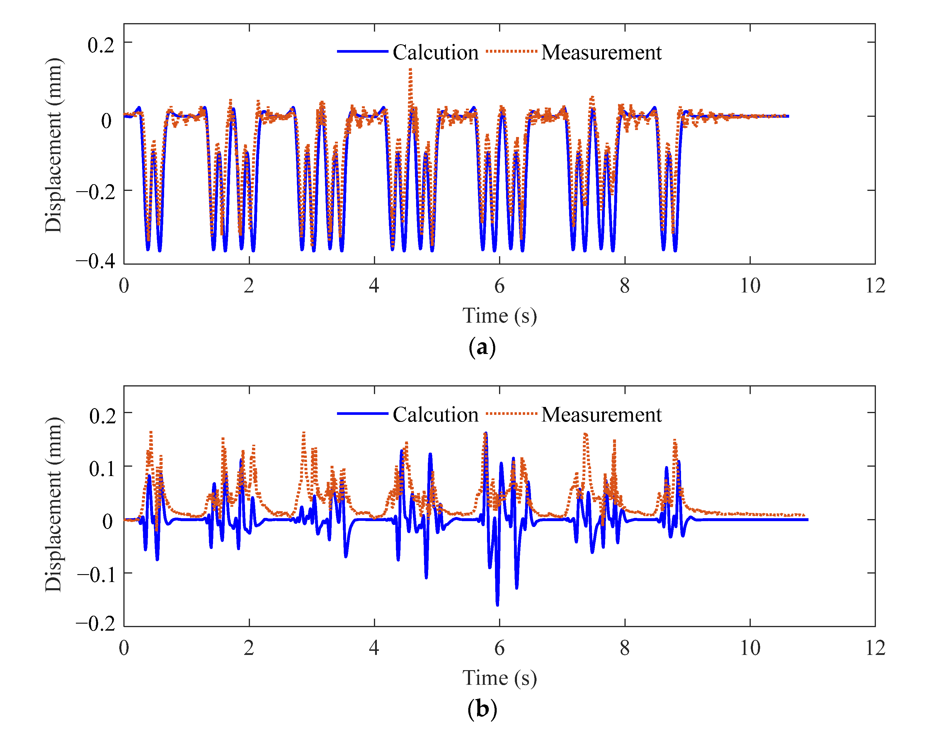
Section 3, the computational model is validated by comparison with the analytical solution, the nonlinear contact model and the measured results;
- ○
In
Section 4, the dynamic response of the track and the bridge and the wheel–rail contact force are analyzed.
2. Dynamic Coupled Equation
2.1. Model Overview
The spatial vehicle–track–bridge interaction model is shown in
Figure 1. The 3-D train–track–bridge coupled dynamic equation with normal supporting track is established based on the virtual work principle. The spatial interaction forces between the wheel–rail and the bridge–rail reflect the dynamic coupled relationship between the substructures. Besides, it is assumed that the track and bridge lose the interaction force to simulate the unsupported track. Each vehicle has multiple rigid bodies, composed of a carriage, trailing bogie, leading bogie, four wheelsets, primary suspension between carriage and bogie, and secondary suspension between bogie and wheelset. The train keeps a constant speed across the track line. The longitudinal connection and vibration between each vehicle are ignored.
The spatial vehicle–track–bridge coupled dynamic model is based on the following assumptions:
- (1)
The 3-D finite element model adopted the Euler–Bernoulli beam, each of which has translation along X, Y, and Z directions and rotation around X, Y, and Z axes;
- (2)
The bridge–rail coupled elements are connected by a single-layer discrete spring and dashpot. The rail and the sleeper are treated as a whole, and the position of each sleeper is used as a discrete support point;
- (3)
The linearized Hertz contact theory is used to simulate the wheel–rail geometric relationship in the vertical and lateral directions;
- (4)
Each vehicle has 27 degrees of freedom (DOFs). Each carriage and bogie have five DOFs including lateral, vertical, rolling, pitching, and yawing motion and each wheelset have three DOFs including lateral, vertical, and rolling motion;
- (5)
Each track line consists of the left-side rail and the right-side rail distributed on both sides of the centerline of the bridge or subgrade symmetrically.
2.2. The Equation of Motion for Bridge
The bridge is divided into a series of uniformly spaced beam elements, the length of which is denoted by lb. The longitudinal displacement, vertical displacement, lateral displacement, torsion, angular around Z axes, and angular around Y axes of each node are denoted by , , , , , and respectively. There are m springs and dashpots in each element to connect the bridge with the track. The symbols and denote the vertical stiffness and damping coefficient, and the symbols and denote the lateral stiffness and damping coefficient at each join point respectively. The superscripts “” and “” denote the first and second derivatives with respect to time, and the superscripts “′” and “″” denote the first and second derivatives with respect to coordinates.
The stress of the bridge in the equilibrium position is divided into inertial force, its elastic resilience and damping force, and the elastic and damping forces of the bridge–rail connection. The equation of motion for the element of bridge based on the virtual work principle can be expressed by:
where
f denotes the eccentric distance of the left-side rail and the right-side rail;
is the vertical distance between the bridge deck and the torsional center of the bridge.
The node displacement components at both ends of each bridge element can be expressed by:
The longitudinal displacement, vertical displacement, lateral displacement, and angular of each bridge element at the coordinates
x using the Hermite interpolation function can be expressed by:
2.3. The Equation of Motion for Track
The single-line track is assembled by the left-side rail and the right-side rail, which are symmetric with respect to the central line of the bridge. The track system is composed of a single-layer rail ignoring the elastic contact between the track slab and the bridge deck. The elastic support under the track is provided by rubber pad. The left-side and right-side rails are divided into a series of uniformly spaced beam elements, the length of which are respectively denoted by lrL and lrR.
The mathematical model avoids the separate modeling of wheel–rail vertical contact and wheel–rail vertical separation. Based on assumption (2), the linear stiffness coefficient of the vertical Hertz contact is uniformly expressed by
. The contact coefficient
a should satisfy the following piecewise function considering no tension in the vertical wheel–rail connection.
The vertical geometric compatibility condition at the
kth wheelset can be expressed by:
where
and
denote the vertical and rolling motion of the wheelset;
n = 1, 2 denotes the left-side and right-side wheel respectively;
denotes the vertical displacement of the rail at the contact coordinates
and the moment
t;
denotes the vertical irregularity of the rail.
The stress of the rail in the equilibrium position is divided into inertial force, its elastic resilience and damping force, the elastic and damping forces of the bridge–rail connection, and the elastic force of the wheel–rail connection. The equation of motion for the element of left-side rail based on the virtual work principle can be expressed by:
where
denotes lateral wheel–rail contact stiffness;
and
denote the left-side vertical and lateral rail irregularity respectively;
e is the half of lateral distance between contact points of wheelset and rail.
The node displacement components at both ends of the left-side rail element can be expressed by:
The longitudinal displacement, vertical displacement, lateral displacement, and angular of the left-side rail at the coordinates
x using the Hermite interpolation function can be expressed by:
The equation of motion for the element of the right-side rail based on the virtual work principle can be expressed by:
where
and
denote the right-side vertical and lateral rail irregularity respectively.
The node displacement components at both ends of the right-side rail element can be expressed by:
The longitudinal displacement, vertical displacement, lateral displacement, and angular of the right-side rail at the coordinates
x using the Hermite interpolation function can be expressed by:
2.4. Wheel–Rail Coupled Term for Wheelset
The 27-DOFs matrices for a 4-axle 2-bogie vehicle are deduced in Ref. [
25]. The displacement components of each vehicle can be expressed by:
The displacement components of carriage, leading bogie, trailing bogie, and four wheelsets can be expressed by:
The wheelset is coupled with the track element through the Hertz contact spring. Therefore, it is only necessary to update the wheel–rail coupled and wheelset terms matrix in the lateral, vertical, and rolling DOFs. The equation of motion for the wheel–rail coupled term based on the virtual work principle can be expressed by:
where
,
, and
denote the lateral, vertical, and rolling angular of the wheelset, respectively.
2.5. Assemble Train–Track–Bridge Coupled Matrix
The 3-D vehicle–track–bridge coupled matrix is assembled according to the rule of “sit in the right seat”. The 3-D train–track–bridge interaction system can be expressed by:
where the subscripts “
bb”, “
rL”, “
rR”, and “
vv” denote the bridge, the left-side rail, the right-side rail, and the vehicle respectively.
The mass matrix of the bridge can be expressed by:
The mass matrix of the left-side rail can be expressed by:
The mass matrix of the right-side rail can be expressed by:
The damping matrix of the bridge can be expressed by:
The damping matrix of the left-side rail can be expressed by:
The damping matrix of the right-side rail can be expressed by:
The damping coupled matrix of the left-side rail and the bridge can be expressed by:
The damping coupled matrix of the right-side rail and the bridge can be expressed by:
The stiffness matrix of the bridge can be expressed by:
The stiffness matrix of the left-side rail can be expressed by:
The stiffness matrix of the right-side rail can be expressed by:
The stiffness coupled matrix of the left-side rail and the bridge can be expressed by:
The stiffness coupled matrix of the right-side rail and the bridge can be expressed by:
The additional stiffness matrix of the wheelset can be expressed by:
The stiffness coupled matrix of the wheelset and the left-side rail can be expressed by:
The stiffness coupled matrix of the wheelset and the right-side rail can be expressed by:
The self-motivated force matrix of the left-side rail due to rail irregularity can be expressed by:
The self-motivated force matrix of the right-side rail due to rail irregularity can be expressed by:
The self-motivated force matrix of the wheelset due to rail irregularity and wheelset gravity can be expressed by:
When the supporting stiffness and damping of the rail pad vary unevenly along the longitudinal direction of the track, that is, when the elastic support of the track is irregular, different points of contact are assigned by the changed stiffness and damping coefficient in the mathematical model. The spring–dashpot element is removed at the position where the track fails to be supported that is .
The Newmark-β method with β = 0.25 and γ = 0.5, and the time step with ∆t = 0.001 s are adopted to solve the equations of motion for the 3-D vehicle-rail-bridge interaction system. The computational program of the 3-D train–track–bridge interaction system with the unsupported track is coded in MATLAB.
4. Dynamic Response of Unsupported Track
Numerical modeling described in
Section 2 is applied to investigate the dynamic response of the unsupported track. Referring to the architectural drawings of a high-speed trackway bridge that is a simply supported box girder in China, the structural parameters of the bridge are as follows: span
Lb = 32 m; Young’s modulus
Eb = 34.5 GPa; Poisson ratio 0.2; vertical moment of inertia
Iby = 11.1 m
4; lateral moment of inertia
Ibz = 93.8 m
4; twisting moment of inertia
Ibx = 22.7 m
4; mass per unit length
mb = 43,630 kg/m; Rayleigh damping ratio ζ = 0.02; cross-sectional area
Ab = 8.98 m
4; vertical distance between the bridge deck and the torsional center of girder cross section
hb = 1.05 m. The fundamental frequency of the bridge is 4.6 Hz, and the theoretical resonance speed is 108 m/s. A train consisting of 5 vehicles moves over the bridge at a speed of 100 m/s, which is close to the resonance speed.
The track is comprised of spatial beam elements, wheel–rail connection elements, and bridge–rail connection elements. The detailed properties of the track materials are as follows: element length Lr = 1 m; Young’s modulus Er = 206 GPa; Poisson ratio 0.2; vertical moment of inertia Iby = 5.24 × 10⁻⁶ m4; lateral moment of inertia Ibz = 3.217 × 10⁻⁶ m4; mass per unit length mr = 60.64 kg/m; eccentric distance of the left-side and right-side rail f = 0.757 m; vertical connected stiffness coefficient between rail and bridge = 6 × 10⁷ N/m; vertical connected damping coefficient between rail and bridge = 7.5 × 10⁴ N·s/m; lateral connected stiffness coefficient between rail and bridge = 1.5 × 10⁷ N/m; lateral connected damping coefficient between rail and bridge = 6 × 10⁴ N·s/m. The length of the subgrade in the transition section at both ends of the bridge is taken as 12 m, and the total length of the track is 56 m.
The parameters of the vehicle with 27 DOFs are the same as those in Ref. [
30]. A Hertz spring is used to simulate wheel–rail contact, and both vertical stiffness coefficient
and lateral stiffness coefficient
are 1.4 × 10
8 N/m.
4.1. Unsupported Sleeper on Both Sides
The defect of track support belongs to dynamic irregularity. Its effect on the dynamic response of the train–track–bridge interaction system is greater than that of geometric irregularity. Therefore, the dynamic analysis of this paper only considers the effect of dynamic irregularity but does not consider the effect of geometric irregularity.
As shown in
Figure 5a, continuous unsupported and normally supported sleepers in the bridge and subgrade sections are selected for numerical analysis. The dynamic analysis is carried out at midpoint A of the transition section and point B of the mid-span of the bridge, which are adjacent to the defect area.
Figure 5b shows that the supports on the left and right sides of the same sleeper are invalid.
As can be seen from
Figure 6, compared with the normal support under the track, the effect of one bilateral unsupported sleeper on the displacement of the bridge can be ignored. However, the effect of one bilateral unsupported sleeper increases the acceleration in the midspan of the bridge, resulting in high-frequency oscillations significantly. The maximum acceleration under one bilateral unsupported sleeper increases from 0.3112 m/s
2 to 0.4928 m/s
2, which is about 1.58 times higher than that of normal support. It suggests that the force at the original coupled location is dispersed to nearby area due to the loss of bridge–rail connection, resulting in a significant increase in the acceleration of the bridge.
As can be seen from
Figure 7, when both the left and right sides of the same sleeper are not supported, the vertical wheel–rail contact forces on the left and right sides are the same. The vertical wheel–rail contact force exhibits periodic changes when the vehicle runs smoothly. The reason for the irregular change in the wheel–rail interaction force at the beginning is that the vehicle suddenly exerts a load on the track. The maximum wheel–rail interaction force under one bilateral unsupported sleeper increases from 137.4 kN to 173.9 kN, which is 1.27 times higher than that of normal support. When the train passes through the support defect under the track, the uneven cosine settlement causes the sudden change of the relative displacement between the wheel and the track, which leads to the aperiodic change of the wheel–rail contact force.
Figure 8 shows the bridge acceleration and wheel–rail vertical force under different numbers of the unsupported sleeper at point B. As the number of unsupported sleepers increases, the effect of defects becomes more and more serious. When two sleepers under the track fail to be supported on both sides, the maximum acceleration and wheel–rail interaction force are respectively 0.5458 m/s
2 and 184.6 kN, which are 1.75 and 1.34 times higher than that of normal support. It indicates that the support defect under the track leads to the loss of the buffering effect in the defect area of the track. The greater the wheel–rail contact force is, the greater the dynamic response in the adjacent defect area is.
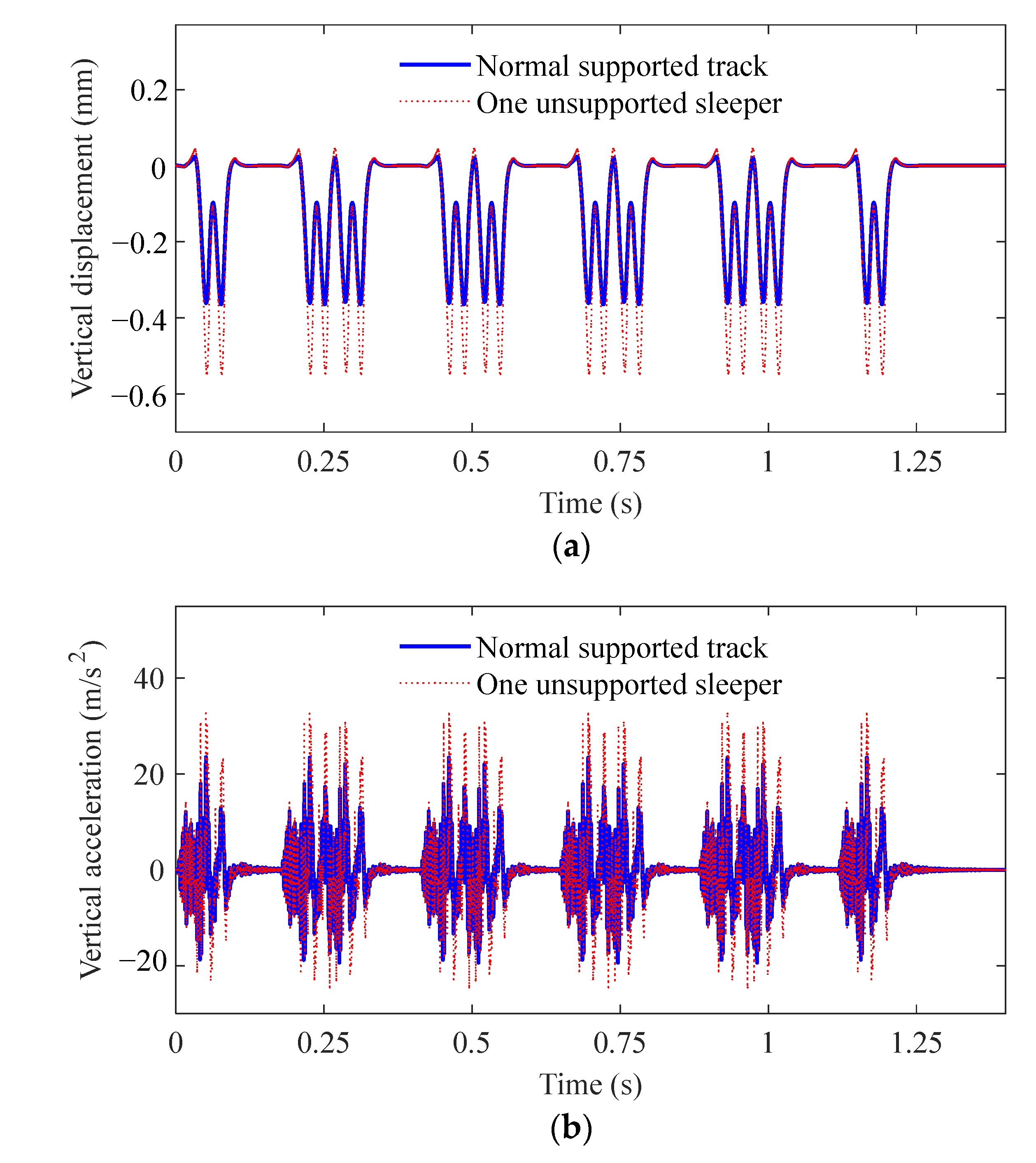
The track is directly supported by the subgrade in the transition section.
Figure 9 shows the displacement and the acceleration at point A, and the driving speed of the train is also 100 m/s. The maximum displacement and the acceleration under one bilateral unsupported sleeper increase from 0.3639 mm to 0.5479 mm and 23.43 m/s
2 to 32.62 m/s
2 respectively, which are about 1.51 times and 1.39 times higher than that of normal support. It indicates that when the track vibration is caused by the high-speed train, the subgrade can significantly reduce the impact on the track. When the train passes through the defect area of the unsupported track, the wheel–rail force is shared by the normal support section adjacent to the defect area.
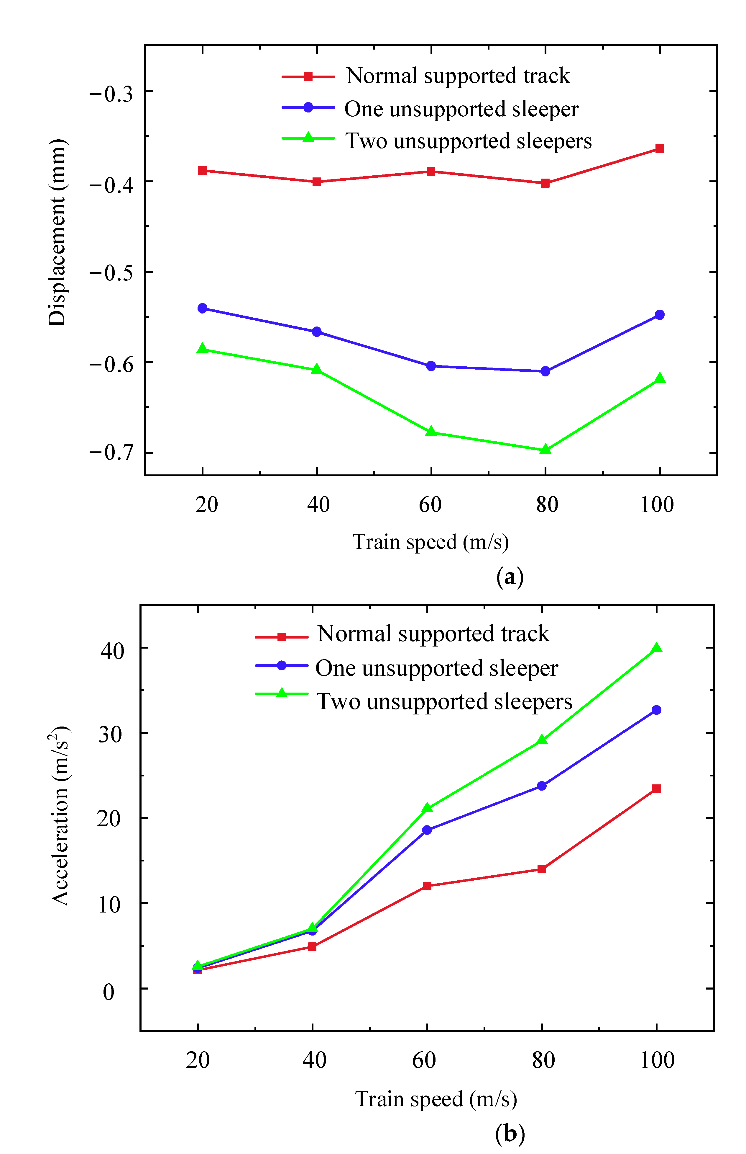
Figure 10 further illustrates the effect of the difference in the driving speed and the degree of the defects under the track. It can be seen that the more serious the support defect of the track, that is, the more unsupported sleepers under the track, the more significant the sharp increase of track displacement and acceleration at the same speed. For example, when two bilateral unsupported sleepers occur and the driving speed is 20 m/s, the maximum displacement of the track at point A is 0.5861 mm, and the maximum acceleration is 2.549 m/s
2. When the driving speed is 80 m/s, the maximum displacement is 0.6974 mm, which is 1.73 times higher than that of normal support. When the driving speed is 100 m/s, the maximum acceleration is 39.89 m/s
2, which is 1.70 times higher than that of normal support. It indicates that the effect of driving speed on track acceleration is greater than that of the number of unsupported sleepers, and the effect of the number of unsupported sleepers on track displacement is more significant.
4.2. Unsupported Sleeper on One Side
This section analyses the dynamic response of the unsupported sleeper on one side. The front view of the unsupported sleepers on one side is the same as
Figure 5a, and the lateral view of the unsupported left rail is shown in
Figure 11.
As can be seen from
Figure 12, the effect of one unilateral unsupported sleeper can be ignored in the displacement of the bridge, which is the same as that of the bilateral unsupported sleeper. However, the maximum acceleration of one unsupported sleeper on one side is less than that on both sides. The maximum acceleration of the left rail with one unilateral unsupported sleeper is 0.3951 m/s
2, while that with one bilateral unsupported sleeper is 0.4928 m/s
2.
Figure 13 shows that the maximum wheel–rail interaction force on the left and right sides are 172.3 kN and 142.4 kN respectively, which are about 1.25 and 1.04 times higher than that of normal support. It indicates that the rolling force of the vehicle leads to the change of the wheel–rail force on the intact side due to the inconsistency of the supporting stiffness of the left-side rail and the right-side rail.
Figure 14 shows the bridge acceleration and wheel–rail vertical force of the left-side and right-side rail under the different numbers of unsupported sleepers at point B. When there are two unilateral unsupported sleepers, the maximum acceleration is 0.4205 m/s
2, which is about 1.35 times higher than that of normal support. The wheel–rail interaction force of the left-side and right-side rail is 182 kN and 143.7 kN, respectively, which are 1.32 and 1.05 times higher than those of normal support. It indicates that the acceleration of the bridge under the unilateral unsupported sleepers is smaller than the acceleration of the bilateral unsupported sleepers. The wheel–rail contact force on the unsupported side of the unilateral unsupported sleeper is slightly smaller than that of the bilateral unsupported sleeper, while the wheel–rail contact force on the supporting side of the unilateral unsupported sleeper is slightly larger than that of the normal supporting sleeper.
As can be seen from
Figure 15, the maximum displacement of the left-side and right-side rails under one unilateral unsupported sleeper are 0.5355 mm and 0.3729 mm respectively, which are about 1.47 times and 1.02 times higher than those under normal support. The maximum acceleration of the left-side and right-side rail under one unilateral unsupported sleeper are 31.92 m/s
2 and 24.2 m/s
2 respectively, which are about 1.36 times and 1.03 times higher than those under normal support. It indicates that for the unilateral supported sleeper, the dynamic response of the track has a significant effect on the unsupported side, but the effect on the other supporting side can be ignored.
Figure 16 shows the dynamic response of the left-side and right-side rail at point A. When there are two unilateral unsupported sleepers and the driving speed is 100 m/s, the maximum displacement and acceleration of the left-side rail are respectively 0.6014 mm and 38.74 m/s
2, which are about 1.65 and 1.65 times higher than those of normal support. The maximum displacement and acceleration of the right-side rail are, respectively, 0.3767 mm and 24.74 m/s
2, which are about 1.04 and 1.06 times higher than those of normal support. It indicates that when unilateral unsupported sleepers occur, the dynamic response of the unsupported track is slightly smaller than that when bilateral unsupported sleepers occur. For unilateral unsupported sleepers, the unsupported side has a limited effect on the other supporting side.
5. Conclusions
In this paper, two possible real-world scenarios of the unsupported track are investigated for the first time. One of the real scenarios is that unsupported track occurs on the bridge. Another real scenario is unilateral and bilateral unsupported sleepers on the same track line.
An effective method for establishing the spatial vehicle–track–bridge interaction model based on the virtual work principle can avoid directly analyzing the complex equilibrium compatibility and geometric compatibility of the wheel–rail and bridge–rail contact interface. When the support under the track is defective, the original assembled 3-D vehicle–track–bridge system matrix is updated by removing the coupled term of the discrete connection between the bridge and the track.
This model and method are applied to investigate the wheel–rail contact force, and the dynamic responses of the bridge and the track under the unsupported sleepers. The following conclusions can be drawn from the studies:
- (1)
The support defects under the track have little effect on the displacement of the bridge, but they increase the acceleration of the bridge. When the sleepers fail to be supported on one side, the acceleration of the bridge is smaller than that when the sleepers fail to be supported on both sides;
- (2)
When the vehicles run smoothly and the track is well supported, the vertical wheel–rail contact force changes periodically. However, the vertical wheel–rail contact force suddenly changes when the train passes through the supporting defect area under the track. Whether it is unilateral or bilateral support failure, the changing trend of the contact force on the unsupported side of the track is the same. The rolling force of the vehicle results in the change of the wheel–rail contact force on the intact side due to the inconsistency of the supporting stiffness of the left-side and right-side rails;
- (3)
When one sleeper is unsupported, the vertical displacement and acceleration of the track change little. When the disease develops into two unsupported sleepers, the dynamic response increases significantly. The effect of driving speed on track acceleration is greater than that of the number of unsupported sleepers, and the effect of the number of unsupported sleepers on track displacement is more significant;
- (4)
For unilateral unsupported sleepers, the dynamic response on the unsupported side is slightly smaller than that of the bilateral unsupported sleeper, while the unsupported side has limited influence on the other supporting side. Therefore, the trackway department should repair the defects under the track in time, and remind the train drivers to pass through the diseased area at a low speed.

