Article

Propagation Characteristics of Rotation Waves in Transversely Isotropic Granular Media Considering Microstructure Effect

Department of Civil Engineering, University of Science and Technology Beijing, Beijing 100083, China
*
Author to whom correspondence should be addressed.
Appl. Sci. 2022, 12(12), 6129; https://doi.org/10.3390/app12126129
Submission received: 12 May 2022 / Revised: 10 June 2022 / Accepted: 15 June 2022 / Published: 16 June 2022
(This article belongs to the Section Civil Engineering)

Abstract

:
The purpose of this study is to develop a micromechanical-based microstructure model for transversely isotropic granular media and then use it to investigate the propagation characteristics of particle rotation waves. In this paper, the particle translation and rotation are selected as basic independent variables and the particle displacement at contact due to particle rotation is ignored. The relative deformation tensors are introduced to describe the local deformational fluctuation because of their discrete nature and microstructure effect. Based on micro–macro deformation energy conservation, the constitutive relations are derived through transferring the summation into an integral and introducing the contact fabric tensor. The governing equations and corresponding boundary conditions can then be obtained based on Hamilton’s principle. Subsequently, the dispersion characteristics and bandgap features of particle rotation waves in transversely isotropic granular media are analyzed based on the present model. The research shows that: the present microstructure model can predict 12 particle rotation waves and reflect 8 dispersion relations; the effect of the change in fabric on the dispersion relation of particle rotation waves can be mainly attributed to the effect of equivalent stiffness on frequency; and the degree of anisotropy has significant effects on the width of frequency bandgap of longitudinal waves, while it has little effect on the width of frequency bandgap of transverse and in-plane shear waves.

1. Introduction

The study of understanding the physical properties and mechanical behaviors of granular media has always been a subject of interest [1,2,3,4,5,6]. Investigating the propagation characteristics of elastic waves helps to better understand the mechanical response of granular materials to external loading. For example, for geotechnical materials, the wave velocity can be used as an important mechanical index to assess the small strain modulus [7] and anisotropy [8], and the elastic wave theory can be applied to engineering fields, such as foundation liquefaction, geological exploration, and structural seismic resistance [9].
Generally, there are two classes of method used in modeling the mechanical behaviors of granular media, called discrete element method and equivalent continuum method. In recent years, due to the rapid development of computer technology and numerical software, many breakthroughs have been achieved in understanding the static and dynamic properties of granular materials from a microscale viewpoint based on the discrete element method [10,11,12]. On the other hand, the continuous method is always a convenient and effective method to describe the mechanical properties of materials [13,14,15]. For granular materials, it is widely accepted that the modelling of granular media should incorporate the microscale information from particle level to capture more comprehensive microscale properties and hence model more complex mechanical behaviors. On this basis, many researchers have attempted to develop multiscale constitutive models considering the effect of microscale (particle) kinematics. For example, some micromechanics-based models considering particle kinematics and/or their high-order gradient terms are established [16,17,18,19,20]. As for wave propagation in granular media, many researchers have proved that the micromechanics-based models, such as the Cosserat model, micropolar model, high-gradient model, and other multiscale models, can describe well the propagational behaviors of plane waves and surface waves [21,22,23,24]. Recently, when considering the local fluctuation of particle kinematics within granular media, Misra et al. [25,26,27] developed a micromorphic model for granular materials based on micromechanical analysis and apply it to study the dispersion behaviors and bandgap features of elastic waves. The micromorphic model, also called the microstructure model, was firstly established by Mindlin and Eringen [28,29] for solids with microstructure. Based on the work of Misra et al., Xiu et al. [30,31] proposed a simplified micromorphic model considering only the first-order gradient of particle displacement and rotation and then also analyzed the propagation characteristics of plane waves.
It is generally assumed that the granular materials are homogeneous and isotropic in these micromorphic (or microstructure) models. However, granular media, especially for geotechnical materials, show different degrees of anisotropy due to their depositional conditions or external loading effects. Furthermore, much research has shown that the fabric anisotropy has a significant impact on the macroscale and microscale mechanical properties of granular materials [32,33,34,35]. In addition, the relative displacement and rotation at contacts are considered as basic independent variables in these models [25,26,27,30,31]. However, particle displacement and rotation are interrelated. It would lead to problem of double counting in the calculation of strain energy and kinematic energy in their models.
Different from the existing micromorphic models mentioned above, in this paper, the particle translation and rotation are selected as basic independent variables in this model and the particle displacement at contact due to particle rotation is ignored for simplicity. In this way, the problems of double counting in the calculation of strain energy and kinematic energy would disappear because these two variables are naturally independent. The deformation energy of granular materials is defined from macroscopic and microscopic levels. On this basis and considering the effect of fabric anisotropy, a micromechanical-based microstructure continuum model is developed for transversely isotropic granular media based on Hamilton′s principle and micro–macro energy conservation and then applying it to study the propagational characteristics of particle rotation waves, i.e., dispersion characteristics and frequency bandgaps. The fabric anisotropy caused by different contact distributions in different directions is considered in this paper. The wave equations and dispersion relations of particle rotation waves were obtained and then the effects of anisotropy and contact stiffness ratio on the wave dispersion relations and bandgaps are discussed in detail.
In this paper, the scalar variables are denoted in italic characters (e.g., particle n), and the vectors are denoted in bold italic characters (e.g., displacement vector u ). As for tensors, the second order tensor is represented in bold upright letters (e.g., strain tensor ε ), while the tensors greater than second order are represented in double-struck characters, with the superscript denoting the orders of the tensor (e.g., A 3). The symbols used in this paper are listed Abbreviation part.

2. The Microstructure Model Considering Nonaffine Deformations

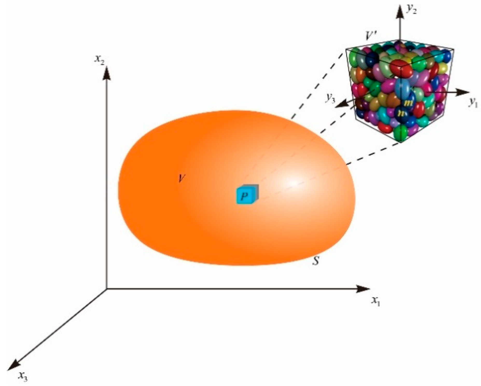
2.1. Macroscale and Microscale Deformations

A material point composed of a large number of particles with the volume V and bounded by surface S can be generally viewed as a continuum (see Figure 1). In classical continuum theory or other enhanced continuum models, the macroscale deformations are generally considered to be homogeneous within the material point, which can be generally denoted by strain ε for linear deformation and curvature κ for bending (or twist) deformation, defined as:
ε = 1 2 ( u + ( u ) T ) , κ = 1 2 ( ϖ + ( ϖ ) T )
where u denotes the macroscale displacement vector, and ϖ denotes the macroscale rotation vector.
As we know, however, numerous experimental and numerical results have shown that particles inside the granular media undergo significant nonaffine motions under external loading because of its discrete nature and microstructure. When considering the microstructure effect and this nonaffine deformation of microstructure, we introduce a second rectangular coordinate system y , a so-called microscale coordinate system parallel to the macroscale coordinate system x , the origin of which is attached to the barycenter of the microstructure unit (or unit cell) P, as shown in Figure 1. Hence, the kinematics of particles within a unit cell are the function of not only the macroscale coordinate system x but also the microscale coordinate system y .
At the microscale level, the translation v and the rotation ω of particle n, according to [18,19], can be approximated from the deformation of its neighboring particle m using a polynomial expansion:
v n ( x , y n ) = v m ( x , y m ) + A ( x ) · ( y n y m ) + 1 2 A 3 ( x ) · ( y n y m ) · ( y n y m ) ,
ω n ( x , y n ) = ω m ( x , y m ) + B ( x ) · ( y n y m ) + 1 2 B 3 ( x ) · ( y n y m ) · ( y n y m ) ,
where A and B are microscale strain and curvature, respectively; A 3 and B 3 are the gradient of microscale strain and curvature, respectively. For simplicity, in this paper, these deformations are assumed to be only dependent on the macroscale coordinate system and hence they are macroscale measures.
Due to the difference between macroscale and microscale deformations, e.g., the difference of A and ε , here we introduce relative deformation tensors to account for these differences, given by
R = ε A ,   3 = A A 3 ;   D = κ B ,   𝔻 3 = B B 3 ,
To simplify the problem, the higher-order relative deformation tensors 𝔻 3 and 3 are assumed to be zero. In other words, the gradient of strain and curvature are homogeneous in the material point.
By substituting Equation (4) into Equations (2) and (3), we can obtain the microscale relative displacement Δ c and rotation θ c between two particles in terms of macroscale deformations:
Δ c = v n v m = A · ( y n y m ) + 1 2 A 3 · ( y n y m ) · ( y n y m ) = ε · l c R · l c + 1 2 A : L c = Δ c a Δ c r + Δ c g ,
θ c = ω n ω m = B · ( y n y m ) + 1 2 𝔹 3 · ( y n y m ) · ( y n y m ) = κ · l c D · l c + 1 2 B : L c = θ c a θ c r + θ c g ,
where l c = y n y m is the branch vector, and L c = l c l c denotes the internal length tensor.

2.2. Governing Equations and Boundary Conditions

Generally, the governing equations and boundary conditions for a continuum are derived based on Hamilton’s principle. Therefore, according to the above analysis of macroscale deformation and microscale kinematics and motivated by Mindlin [28], we give the expressions of the variations of kinetic energy δ T , deformation energy δ W , and the work done by external forces (stresses) δ Q as follows:
δ T = V ( ρ u ¨ · δ u + ρ A ¨ · α : δ A + ρ β ϖ ¨ · δ ϖ + ρ γ B ¨ : δ B ) d V ,
δ W = V [ σ : δ ε + τ : δ R + 𝕋 3 δ ( A )   +   μ : δ κ + υ : δ D + 𝕍 3 δ ( B ) ] d V ,
δ Q = V ( f · δ u + Φ : δ A + k · δ ϖ + Π : δ B ) d V + S ( t · δ u + Ψ : δ A + g · δ ϖ + Γ : δ B ) d S ,
where ρ = 1 V V ρ m d V is the macroscale density, ρ m is the microscale (particle) density, and V is the volume of unit cell (microstructure). α = 1 V V y y d V is the average second order moment of inertia. β = 1 V V y · y d V and γ = 1 V V ( y · y ) 2 d V are the average second and fourth order polar moments of inertia, respectively. Considering one particle as a unit cell for monodisperse granular assemblies, we have β = 2 5 R 2 and γ = 12 35 R 4 , where R is the radius of particles. The σ and μ denote the Cauchy stress tensor and couple stress tensor conjugated to the strain ε and curvature κ , respectively; τ and υ are relative stress and couple stress tensors, respectively; 𝕋3 and 𝕍3 are higher-order stress measures conjugated to the macroscale deformation measures A and B , respectively. f and t are the volume force and surface traction, respectively; Φ and Ψ are the double body force and surface traction, respectively; k and g denote the body moment and surface moment, respectively; Π and Γ denote the double body moment and surface moment, respectively.
Using the Hamilton’s principle 0 t ( δ Q δ W + δ T ) d t = 0 and Gauss divergence theorem, we can easily obtain the following governing equations and boundary conditions for the present microstructure model:
· ( σ + τ ) + f = ρ u ¨ ,
τ + · 𝕋 3 + Φ = ρ α A ¨ ,
· ( μ + υ ) + k = ρ β ϖ ¨ ,
υ + · 𝕍 3 + Π = ρ γ B ¨ ,
( σ + τ ) · n ˜ = t ,
𝕋 3 · n ˜ = Ψ ,
( μ + υ ) · n ˜ = g ,
𝕍 3 · n ˜ = Γ ,
where n ˜ is the unit outwards-pointing normal vector of the boundary surface S.

2.3. Local and Global Constitutive Relations

At particle level, for the elastic regime considered in this paper, the interaction between particles in contact can be regarded as linearly elastic. Hence, ignoring the effect of cross terms, the local constitutive relations for particle pairs (i.e., contact law) can be given as:
f ζ = K ζ · Δ c ζ ,   m ζ = G ζ · θ c ζ ,   ζ = a ,   r ,   g ,
where f ζ is the contact force and m ζ is the contact moment. The linear stiffness K ζ and rotation stiffness G ζ can be expressed as [19,20]
K ζ = ( K n ζ K s ζ ) n n + K s ζ I ,
G ζ = ( G n ζ G s ζ ) n n + K s ζ I ,
where K n ζ and K s ζ are linear displacement stiffnesses at the contact in normal and tangential directions, respectively. G n ζ and G s ζ are rotation stiffnesses in normal and tangential directions, respectively. n is the contact normal vector, which can be expressed as n = cos γ x 1 + sin γ cos φ x 2 + sin γ sin φ x 3 in global coordinate systems (see Figure 2), and I is the second order identity tensor.
Consequently, ignoring the effect of cross terms, the microscale deformation energy increment d w c at a contact can be reasonably defined as follows:
d w c = ζ ( K ζ · Δ c ζ · d Δ c ζ + G ζ · θ c ζ · d θ c ζ ) .
At continuum level, based on the macroscale deformations analysis previously, the macroscale deformation energy density increment d W can be expressed as a function of the macroscale continuum kinematic measures, i.e., d W = d W ( ε , R , A , κ , D , B ) . The following form is adopted in this paper, ignoring the effect of cross terms:
d W = σ : d ε + τ : d R + 𝕋 3 d ( A ) + μ : d κ + υ : d D + 𝕍 3 d ( B ) .
Based on energy conservation, the macroscale deformation energy density should be equal to the volumetric average of the sum of the microscale deformation energy over all contacts for the elastic conditions where the energy dissipation is not considered. Meanwhile, for a material point with a very large number of particles, it is reasonable to use an integral form to replace the summation. Thus, we have
d W = N V V ζ ( K ζ · Δ c ζ · d Δ c ζ + G ζ · θ c ζ · d θ c ζ )   ξ ( γ ,   φ ) sin γ d γ d φ ,
in which N is the total number of contacts and ξ ( γ ,   φ ) denotes the probability density function of contact distribution. For a transversely isotropic granular media,   ξ ( γ ,   φ ) can be approximated by the second-order spherical harmonic function, given in the tensor form by
ξ ( γ ,   φ ) = 1 4 π ( δ + F ) : ( n n ) ,
where δ is the Kronecker tensor, and F denotes the deviatoric tensor of contact distribution, given by
F = [ a 0 0 0 a 2 0 0 0 a 2 ] ,
in which a is the parameter reflecting the degree of anisotropy. The material is isotropic under the case of a = 0.
The macroscale stress measures mentioned in Section 2.2 can then be obtained in terms of macroscale deformations, i.e., global constitutive relations, by the combination of Equations (16) and (17):
σ = W ε = N V w c ξ ( γ ,   φ ) d γ d φ   V ε = ( N p l 2 s K a n n ξ sin γ d γ d φ ) : ε = 4 : ε ,
τ = W R = N p V w c ξ ( γ ,   φ ) d γ d φ   R = ( N p l 2 s K r n n ξ sin γ d γ d φ ) : R = 𝔼 4 : R ,
𝕋 3 = W ( A ) = N p V w c ξ ( γ ,   φ ) d γ d φ   ( A ) = ( N p l 4 4 s K g n n n n ξ sin γ d γ d φ ) d ( A ) = 6 d ( A ) ,
μ = W κ = N V w c ξ ( γ ,   φ ) d γ d φ   V κ = ( N p l 2 s G a n n ξ sin γ d γ d φ ) : κ = 𝕁 4 : κ ,
υ = W D = N V w c ξ ( γ ,   φ ) d γ d φ   V D = ( N p l 2 s G r n n ξ sin γ d γ d φ ) : D = 𝕄 4 : D ,
𝕍 3 = W ( B ) = N p V w c ξ ( γ ,   φ ) d γ d φ   ( B ) = ( N p l 4 4 s G g n n n n ξ sin γ d γ d φ ) d ( B ) = 6 d ( B ) ,
where N p denotes the number of contacts per volume and l is the length of the branch vector.
It can be seen that the present microstructure model consists of six sets of constitutive equations. Equations (20)–(22) are associated with particle displacement, and Equations (23)–(25) are associated with particle rotation. The expressions of constitutive tensors 4 , 𝔼4, 6 , 𝕁4, 𝕄4, and 6 in macroscale constitutive relations can be found in Appendix B.

3. Propagation of Particle Rotation Waves

In this section, the propagation characteristics of elastic plane waves in transversely isotropic granular materials are analyzed using the presented microstructure model. Due to the limited space in this paper, only the particle rotation waves are investigated.

3.1. Wave Equations

By substituting the macroscale constitutive relations associated with particle rotation, Equations (23)–(25), into the governing equations, Equations (10c) and (10d), and ignoring the body forces and moments, we can obtain the following 12 wave equations:
[ ( 5 + 2 a ) ( b 1 + p 1 ) + ( 16 + 10 a ) ( b 2 + p 2 ) ] ϖ 1 , 11 [ ( 5 + 2 a ) p 1 + ( 16 + 10 a ) p 2 ] B 11 , 1 ( 7 + a ) p 2 ( B 22 , 1 + B 33 , 1 ) = ρ β l 2 N p ϖ ¨ 1 ,
[ ( 5 + 2 a ) ( b 1 + p 1 ) + ( 2 a ) ( b 2 + p 2 ) ] ϖ 2 , 11 [ ( 5 + 2 a ) p 1 + ( 2 a ) p 2 ] B 21 , 1 ( 7 + a ) p 2 B 12 , 1 = ρ β N p l 2 ϖ ¨ 2 ,
[ ( 5 + 2 a ) ( b 1 + p 1 ) + ( 2 a ) ( b 2 + p 2 ) ] ϖ 3 , 11 [ ( 5 + 2 a ) p 1 + ( 2 a ) p 2 ] B 31 , 1 ( 7 + a ) p 2 B 13 , 1 = ρ β N p l 2 ϖ ¨ 3 ,
l 2 4 [ ( 21 w 1 + 114 w 2 + 12 w 1 a + 78 w 2 a ) B 11 , 11 + ( 27 w 2 + 9 w 2 a ) ( B 22 , 11 + B 33 , 11 ) ] + [ ( 5 p 1 + 16 p 2 + 4 p 1 a + 8 p 2 a ) ϖ 1 , 1 ( 5 p 1 + 16 p 2 + 4 p 1 a + 8 p 2 a ) B 11 ( 7 p 2 + p 2 a ) ( B 22 + B 33 ) ] = ρ γ l 2 N p B ¨ 11 ,
l 2 4 [ ( 7 w 1 + 20 w 2 w 2 a + w 1 a ) B 22 , 11 + ( 27 w 2 + 9 w 2 a ) B 11 , 11 + 9 w 2 B 33 , 11 ] + ( 7 p 2 + p 2 a ) ( ϖ 1 , 1 B 11 ) ( 5 p 1 + 16 p 2 2 p 1 a 4 p 2 a ) B 22 ( 7 p 2 2 p 2 a ) B 33 = ρ γ l 2 N p B ¨ 22 ,
l 2 4 [ ( 7 w 1 + 20 w 2 w 2 a + w 1 a ) B 33 , 11 + ( 27 w 2 + 9 w 2 a ) B 11 , 11 + 9 w 2 B 22 , 11 ] + ( 7 p 2 + p 2 a ) ( ϖ 1 , 1 B 11 ) ( 5 p 1 + 16 p 2 2 p 1 a 4 p 2 a ) B 33 ( 7 p 2 2 p 2 a ) B 22 = ρ γ l 2 N p B ¨ 33 ,
l 2 4 [ 7 w 1 + 20 w 2 + 8 w 2 a + w 1 a ] B 12 , 11 + l 2 4 ( 27 + 9 a ) w 2 B 21 , 11 + ( 7 + a ) p 2 ( ϖ 2 , 1 B 21 ) ( 5 p 1 + 2 p 2 + p 1 a ) B 12 = ρ γ l 2 N p B ¨ 12 ,
l 2 4 [ 3 ( 7 w 1 + 2 w 2 w 2 a + 4 w 1 a ) B 21 , 11 + 3 ( 9 w 2 + 3 w 2 a ) B 12 , 11 ] + [ ( 5 p 1 + 2 p 2 + p 1 a ) ( ϖ 2 , 1 B 21 ) ( 7 p 2 + p 2 a ) B 12 ] = ρ γ l 2 N p B ¨ 21 ,
l 2 4 ( 7 w 1 + 20 w 2 + 8 w 2 a + w 1 a ) B 13 , 11 + l 2 4 ( 27 + 9 a ) w 2 B 31 , 11 + ( 7 + a ) p 2 ( ϖ 3 , 1 B 31 ) ( 5 p 1 + 2 p 2 + p 1 a ) B 13 = ρ γ l 2 N p B ¨ 13 ,
l 2 4 [ 3 ( 7 w 1 + 2 w 2 w 2 a + 4 w 1 a ) B 31 , 11 + 3 ( 9 w 2 + 3 w 2 a ) B 13 , 11 ] + [ ( 5 p 1 + 2 p 2 + p 1 a ) ( ϖ 3 , 1 B 31 ) ( 7 p 2 + p 2 a ) B 13 ] = ρ γ l 2 N p B ¨ 31 ,
l 2 4 [ ( 7 w 1 + 2 w 2 w 2 a + w 1 a ) B 23 , 11 + 9 w 2 B 32 , 11 ] [ ( 5 p 1 + 2 p 2 2 p 1 a ) B 23 + ( 7 2 a ) p 2 B 32 ] = ρ γ l 2 N p B ¨ 23 ,
l 2 4 [ ( 7 w 1 + 2 w 2 w 2 a + w 1 a ) B 32 , 11 + 9 w 2 B 23 , 11 ] [ ( 5 p 1 + 2 p 2 2 p 1 a ) B 32 + ( 7 2 a ) p 2 B 23 ] = ρ γ l 2 N p B ¨ 32 .
To simplify the derivation without the loss of generality, here we consider the case where the rotation waves propagate in one direction only (plane waves). Hence, the general solutions of above wave equations can be assumed in a harmonic form as follows:
ϖ = Ω i e i ( k x 1 ω t ) , B = Θ e i ( k x 1 ω t ) ,
where Ω and Θ are the amplitudes of macroscale rotation and the gradient of rotation, respectively, ω is the angular frequency, and k is the wave number.
Substituting Equation (38) into wave Equations (26)–(37) yields the following 12 equations after some rearrangements:
( L 11 k 2 ρ β l 2 N p ω 2 ) Ω 1 + L 12 k Θ ¯ + L 13 k Θ D = 0 ,
L 21 k Ω 1 + ( L 22 k 2 + L 22 3 ρ γ l 2 N p ω 2 ) Θ ¯ + ( L 23 k 2 + L 23 ) Θ D = 0 ,
L 31 k Ω 1 + ( L 23 k 2 + L 23 ) Θ ¯ + ( L 33 k 2 + L 33 3 ρ γ 2 l 2 N p ω 2 ) Θ D = 0 ,
( T 11 k 2 ρ β l 2 N p ω 2 ) Ω 2 + T 12 k Θ ( 21 ) + T 13 k Θ [ 12 ] = 0 ,
T 21 k Ω 2 + ( T 22 k 2 + T 22 2 ρ γ l 2 N p ω 2 ) Θ ( 12 ) + T 23 k 2 Θ [ 12 ] = 0 ,
T 31 k Ω 2 + T 23 k 2 Θ ( 12 ) + ( T 33 k 2 + T 33 2 ρ γ l 2 N p ω 2 ) Θ [ 12 ] = 0 ,
( T 11 k 2 ρ β l 2 N p ω 2 ) Ω 3 + T 12 k Θ ( 31 ) + T 13 k Θ [ 13 ] = 0 ,
T 21 k Ω 3 + ( T 22 k 2 + T 22 2 ρ γ l 2 N p ω 2 ) Θ ( 13 ) + T 23 k 2 Θ [ 13 ] = 0 ,
T 31 k Ω 3 + T 23 k 2 Θ ( 13 ) + ( T 33 k 2 + T 33 2 ρ γ l 2 N p ω 2 ) Θ [ 13 ] = 0 ,
( S 11 k 2 + S 11 ρ γ l 2 N p ω 2 ) Θ ( 23 ) = 0 ,
( S 11 k 2 + S 11 ρ γ l 2 N p ω 2 ) ( Θ 22 Θ 33 ) = 0 ,
( S 22 k 2 + S 22 ρ γ l 2 N p ω 2 ) Θ [ 23 ] = 0 ,
where Θ ¯ = 1 3 tr ( Θ ) , Θ D = Θ 11 Θ ¯ . The subscripts ( ) represent the symmetric part of the tensor and [ ] represents its skew part. The coefficients in Equations (39)–(50) can be found in Appendix C.

3.2. Dispersion Relations

According to the wave Equations (39)–(50), we can obtain four sets of dispersion relations for particle rotation waves, including one set of rotation longitudinal waves related to the kinematic components ϖ 1 , B ¯ , and B D (Equations (39)–(41)), two sets of rotation transverse waves related to the kinematic components ϖ 2 , B ( 12 ) , and B [ 12 ] (Equations (42)–(44)) and ϖ 3 , B ( 13 ) , and B [ 13 ] (Equations (45)–(47)), and one set of rotation in-plane shear waves related to the kinematic components B ( 23 ) , B [ 23 ] , and B 22 B 33 (Equations (48)–(50)). Their dispersion equations are as follows:
(1) Rotation Longitudinal Waves: associated with ϖ 1   B ¯ , and B D
| L 11 k 2 ρ β l 2 N p ω 2 L 12 k L 13 k L 21 k L 22 k 2 + L 22 3 ρ γ l 2 N p ω 2 L 23 k 2 + L 23 L 31 k L 23 k 2 + L 23 L 33 k 2 + L 33 3 ρ γ 2 l 2 N p ω 2 | = 0
(2) Rotation Transverse Waves: related to ϖ 2 , B ( 12 ) , and B [ 12 ]
| T 11 k 2 ρ β l 2 N p ω 2 T 12 k T 13 k T 21 k T 22 k 2 + T 22 2 ρ γ l 2 N p ω 2 T 23 k 2 T 31 k T 23 k 2 T 33 k 2 + T 33 2 ρ γ l 2 N p ω 2 | = 0
(3) Rotation Transverse Waves: related to ϖ 3 , B ( 13 ) , and B [ 13 ]
| T 11 k 2 ρ β l 2 N p ω 2 T 12 k T 13 k T 21 k T 22 k 2 + T 22 2 ρ γ l 2 N p ω 2 T 23 k 2 T 31 k T 23 k 2 T 33 k 2 + T 33 2 ρ γ l 2 N p ω 2 | = 0
(4) Rotation in-plane Shear Waves: related to B ( 23 ) , B [ 23 ] , and B 22 B 33
ω ( 23 ) = ω 22 33 = ( S 11 k 2 + S 11 ) l 2 N p ρ γ ,   ω [ 23 ] = ( S 22 k 2 + S 22 ) l 2 N p ρ γ .
Since the granular materials are considered transversely isotropic, the dispersion relations for the two sets of rotation transverse waves are the same. For brevity, hence, we only analyze the characteristics of rotation transverse waves related to the kinematic components ϖ 2 , B ( 12 ) , and B [ 12 ] in the following text.

4. Results and Analysis

4.1. Dispersion Characteristics of Particle Rotation Waves

This section explains the effect of the degree of anisotropy on the dispersion characteristics of particle rotation waves. To facilitate the analysis without the loss of generality, the non-dimensional wave number k ¯ = l 2 π k and the non-dimensional frequency ω ¯ = 4 π ρ R 5 3 G n a ω are adopted in the following analysis. Figure 3 shows the dispersion curves of the three kinds of particle rotation waves under different anisotropic parameter a. Unless stated otherwise, the model parameters adopted in this paper are listed in Table 1 and are the same as that used in [25].
Figure 3a–c show the variation of dispersion relations of rotation longitudinal waves with a. It can be seen that the rotation longitudinal waves include one acoustic branch (LA), the cutoff frequency of which equals zero at k = 0, and two optical branches (LO), the cutoff frequency of which is non-zero. For the LA branch, with the wave number increasing, its frequency increases rapidly at long-wavelength stage and then increases slightly to an asymptote, showing significant dispersion characteristics. Besides, the anisotropic parameter a has little effect on the LA branch for long-wavelength regime ( k ¯ < 0.1 ), while, as the wave number increases, the effect of a becomes significant: the frequency of LA branch increases apparently with the increase in a (see Figure 3a). The LO branch associated with B ¯ first increases slightly and then approximately linearly increases with the wave number increasing. As a increases, the LO branch associated with B ¯ also increases (see Figure 3b). However, the frequency of the LO branch associated with B D experiences a relatively small increase and eventually reaches an asymptotic value, which implies a weak dependence of wave number (see Figure 3c). Different from other longitudinal waves, there is overall decrease in the frequency of the LO branch associated with B D , except for the long-wavelength regime, with an increase in a. Besides, as a increases, the dependence of its frequency on wave number gradually decreases.
Figure 3d–f give the dispersion curves of rotation transverse waves. Similarly, the rotation transverse waves consist of one acoustic branch (TA) and two optical branches (TO). The TA branch and TO branch associated with B ( 12 ) show similar dispersion relations with the LA branch and LO branch associated with B ¯ , respectively. However, the frequencies of these two transverse waves are smaller than that of longitudinal waves and the effect of anisotropic parameter a are also relatively smaller. As for the TO branch associated with B [ 12 ] , with the wave number increasing, the frequency slightly increases to an asymptotic value, showing a weak dependence of wave number similar with LO branch related to B D , and its frequency also increases with respect to a.
Figure 3g–i show the dispersion curves of rotation in-plane shear waves. The three rotation in-plane shear waves are all optical (TSO), and their frequencies remain almost unchanged with the wave number increasing. Besides, the two branches respectively related to the kinematic components B 22 B 33 and B ( 23 ) have the same dispersion relation. With the degree of anisotropy increasing, the frequencies of three TSO branches all decrease.
The change in the contact fabric would cause the change in the contact number in this direction, thus leading to the change in the corresponding equivalent stiffness. It can therefore be simply concluded that the effect of the change in fabric on the dispersion relation of particle rotation waves is mainly reflected in the effect of equivalent stiffness on frequency. For example, an increase in a leads to an increase in the number of contacts in the x 1 direction and, thus, an increase in the equivalent normal and tangential stiffnesses in the x 1 direction. Hence, the frequencies of longitudinal and transverse waves all increase, except for the LO branch associated with B D because the kinematic component B D relating to three directions is relatively complex.

4.2. Frequency Bandgaps of Particle Rotation Waves

Numerous numerical and experimental results indicated that there are frequency bandgaps, in which no waves can propagate, in granular media because of the effect of microstructure. The presented micromorphic model can predict well the presence of frequency bandgaps. Figure 4 illustrates the presence of frequency bandgaps between particle rotation waves. For rotation longitudinal and transverse waves, there are two frequency bandgaps, respectively, i.e., one between acoustic and optical branches (e.g., RLB1) and another between two optical branches (e.g., RLB2). Generally, the width of RLB1 (or RTB1) is larger than that of RLB2 (or RTB2). There is also a frequency bandgap (RSB) between the two TSO branches. Besides, it is expected that the presented model can predict the existence of a bandgap (pink area) in which all the particle rotation waves cannot propagate in the granular media. This property of granular materials can be used to develop new materials for the field of energy absorption or vibration dissipation.
Figure 5 shows the variation of frequency bandgaps with stiffness ratio η . As shown in Figure 5, the contact stiffness ratio has a significant effect on the frequency bandgaps in both width and location (the frequency corresponding to the center of the bandgap). For the bandgaps of longitudinal waves, with the tangential to normal stiffness ratio increasing from 0 to 1, the asymptotic frequency of LA branch slightly increases, and the cutoff frequency of lower-frequency LO branch also increases, resulting in an increase in both the width and the location of bandgap RLB1. On the contrary, the width of bandgap RLB2 gradually decreases to 0, the center of which almost remains constant. The bandwidth and location of RTB1 between the TA branch and the lower-frequency TO branch significantly increase from 0 with regard to stiffness ratio. It is worth noting that the bandwidth of RTB1 becomes zero at the case of η = 0 , where the lower-frequency TO branch disappears. The bandwidth of RTB2 gradually decreases to 0, while its location moves upwards as the stiffness ratio increases. The variation of RSB with stiffness ratio is similar to that of RTB2.
Figure 6 shows the effect of fabric anisotropy on the frequency bandgaps of particle rotation waves. One can see that the anisotropic parameter a has a significant effect on the width of frequency bandgap of longitudinal waves, while it has little effect on the width of frequency bandgap of transverse and in-plane shear waves. Specifically, with the change in a from 0 to 1, the frequency of lower boundary of bandgap RLB1 continuously increases, while the upper boundary first increases slightly and then decreases, which leads to an overall decrease in the bandwidth of RLB1. Especially, it disappears when a = 1.0. The bandwidth of RLB2, however, continuously widens due to the decrease in lower boundary and the increase in upper boundary. With the increase in a, the locations of bandgaps between transverse waves gradually increase, while the location of the bandgap between in-plane shear waves decreases.

5. Conclusions

In this paper, a micromechanical model incorporating the effect of microstructure is developed for transversely isotropic granular media and then applied to study the propagational characteristics of particle rotation waves, i.e., dispersion characteristics and frequency bandgaps. From the point of particle kinematics, we take the particle translation and rotation as independent variables and ignore the particle displacement at contact due to particle rotation. Hence, the total deformation energy of granular media can be expressed as the sum of microscale deformation energy, which can be easily calculated by introducing contact constitutive laws, over all contacts. At macroscale level, the relative deformation tensors are defined to describe the local fluctuation in deformations. The macroscale deformation energy can be assumed to be the product of macroscale deformations and their corresponding stress measures. The governing equations and corresponding boundary conditions can be obtained based on Hamilton’s principle. Subsequently, based on micro–macro energy conservation, the constitutive relations are derived through transferring the summation into an integral and introducing the contact fabric tensor. Then, the dispersion relations and bandgap features of particle rotation waves in transversely isotropic granular media are analyzed, and finally a detailed parametric analysis of the dispersion relations and frequency bandgaps is carried out. The main conclusions in this paper are summarized as follows:
  • The present model can predict 12 particle rotation waves, including 3 rotation longitudinal waves, 6 rotation transverse waves, and 3 rotation in-plane shear waves in the transversely isotropic granular media. These waves can reflect eight kinds of dispersion relations.
  • The effect of the change in fabric on the dispersion relation of particle rotation waves can be mainly attributed to the effect of equivalent stiffness on frequency. With the increase in a, the frequencies of rotation longitudinal and transverse waves increase, except for the lower-frequency LO wave, while all rotation in-plane shear waves decrease.
  • The present model can predict the presence of bandgaps between particle rotation waves. With the increase in stiffness ratio from 0 to 1, the bandwidths of RLB1 and RTB1 gradually increase, while that of other bandgaps decrease to 0.
  • The degree of anisotropy has significant effect on the width of frequency bandgap of longitudinal waves, while has little effect on the width of frequency bandgap of transverse and in-plane shear waves. With the increase in a, the locations of bandgaps between transverse waves gradually increase, while the location of the bandgap between in-plane shear waves decreases.

Author Contributions

Writing—original draft preparation and investigation, P.Y.; conceptualization, methodology, supervision and funding acquisition, Y.L.; writing—review and editing, M.S. and Z.C. All authors have read and agreed to the published version of the manuscript.

Funding

This research was funded by Beijing Natural Science Foundation, grant number 8222020.

Institutional Review Board Statement

Not applicable.

Informed Consent Statement

Not applicable.

Data Availability Statement

The data used to support the findings in this paper are available from the corresponding author upon request.

Acknowledgments

The authors would like to express gratitude to Guangchang Yang for his valuable advice and help in formula derivation.

Conflicts of Interest

The authors declare no conflict of interest.

Abbreviations

SymbolsMeanings
ε Strain tensor
κ Curvature tensor
u Macroscale displacement vector
ϖ Macroscale rotation vector
v Particle translation vector
ω Particle rotation vector
A Micro-strain tensor
B Micro-curvature tensor
A 3The gradient of micro-strain
B 3The gradient of micro-curvature
ρ Macroscale density
ρ m Microscale (particle) density
V The volume of unit cell
α Second order moment of inertia
β Second order polar moments of inertia
τ Relative Cauchy stress tensor
υ Relative couple stress tensor
Φ Double body force tensor
Ψ Double surface traction tensor
Π Double body moment tensor
Γ Double surface moment tensor
K Contact linear stiffness tensor
G Contact rotation stiffness tensor
I Second order identity tensor
δ Kronecker tensor
ξ The probability density function of contact distribution
a Anisotropy parameter
4 , 𝔼4, 𝕄44th order constitutive tensors
6 , 6 6th order constitutive tensors
k Wave number
VThe volume of material point
SThe surface of material point
R , D Relative deformation tensors
3 , 𝔻3Higher-order relative deformation tensors
Δ Relative displacement at contact
θ Relative rotation at contact
l Branch vector
L Internal length tensor
T Kinetic energy
W Deformation energy
Q The work done by external forces
σ Cauchy stress tensor
μ Couple stress tensor
n ˜ Unit outwards-pointing normal vector of the boundary surface S
γ Fourth order polar moments of inertia
𝕋3,𝕍3Higher-order stress tensors
f Volume (body) force vector
t Surface traction vector
k Volume (body) moment vector
g Surface moment vector
f ζ Contact force
m ζ Contact moment
n Contact normal vector
N The total number of contacts
F Deviatoric tensor of contact distribution
N p The number of contacts per volume
Ω The amplitude of rotation vector
Θ The amplitude of micro-curvature tensor
ω Angular frequency

Appendix A

For convenience of expression, we introduce the isotropic directional tensor I i 1 i 2 i 2 m 2 m to denote the integrals of the tensor product of contact normal vector (so-called directional tensor) in macroscale stress expressions, given by
2 m m ! ( 2 m + 1 ) ! I i 1 i 2 i 2 m 2 m = 1 4 π n i 1 n i 2 n i 2 m sin γ d γ d φ ,   m = 1 , 2 ,   3
It is easy to find that, based on the tensor analysis, the isotropic directional tensor I i 1 i 2 i 2 m 2 m has the following properties:
I i j 2 = δ i j
I i j k l 4 = δ i j I k l 2 + δ i k I j l 2 + δ i l I j k 2
I i j k l m n 6 = δ i j I k l m n 4 + δ i k I j l m n 4 + δ i l I j k m n 4 + δ i m I j k n l 4 + δ i n I j k l m 4
I i j k l m n p q 8 = δ i j I k l m n p q 6 + δ i k I j l m n p q 6 + δ i l I j k m n p q 6 + δ i m I j k l n p q 6 + δ i n I j k l m p q 6 + δ i p I j k l m n q 6 + δ i q I j k l m n p 6
Hence, the isotropic directional tensor I i 1 i 2 i 2 m 2 m can be finally expressed in terms of the Kronecker symbol δ i j after some successive substitutions.

Appendix B

Here, we give the detailed derivations of constitutive tensors in Equations (20)–(25). The fourth-order tensor 4 ( C i j k l 4 ) can be obtained as follows using the recurrence relations in Appendix A.
C i j k l 4 = l 2 N p 0 π 0 2 π K i k a n j n l ξ sin γ d γ d φ = l 2 N p ( δ p q + F p q ) 1 4 π [ ( K n a K s a ) n i n k + K s a δ i k ] n j n l n p n q sin γ d γ d φ = l 2 N p ( δ p q + F p q ) [ 1 105 ( K n a K s a ) I i j k l p q 6 + 1 15 K s a δ i k I j l p q 4 ] = l 2 N p ( δ p q + F p q ) [ c 1 δ i k I j l p q 4 + c 2 ( δ i j I k l p q 4 + δ i l I j k p q 4 + δ i p I j k l q 4 + δ i q I j k l p 4 ) ] = l 2 N p [ 5 c 1 δ i k δ j l + c 2 ( 5 δ i j δ k l + 5 δ i l δ j k + 2 I i j k l 4 ) + 2 c 1 δ i k F j l + c 2 ( 2 δ i j F k l + 2 δ i l F j k + 2 F i i I i j k l 4 ) ]
It is noting that the Einstein summation convention is not used for F i i in Equation (A6) nor in what follows. Similarly, the sixth-order tensor 6 ( H i j k l m n 6 ) is derived as follows:
H i j k l m n 6 = l 4 N p 4 K i l g n j n k n m n n ξ sin γ d γ d φ = l 4 N p 4 ( δ p q + F p q ) 1 4 π [ ( K n g K s g ) n i n l + K s g δ i l ] n j n k n m n n n p n q sin γ d γ d φ = l 4 N p 4 ( δ p q + F p q ) [ 1 945 ( K n g K s g ) I i j k l m n p q 8 + 1 105 K s g δ i l I j k m n p q 6 ] = l 4 N p 4 ( δ p q + F p q ) [ h 1 δ i l I j k m n p q 6 + h 2 ( δ i j I k l m n p q 6 + δ i k I j l m n p q 6 + δ i m I j k l n p q 6 + δ i n I j k l m p q 6 + δ i p I j k l m n q 6 + δ i q I j k l m n p 6 ) ] = l 4 N p 4 [ 7 h 1 δ i l I j k m n 4 + h 2 ( 7 δ i j I k l m n 4 + 7 δ i k I j l m n 4 + 7 δ i m I j k l n 4 + 7 δ i n I j k l m 4 + 2 I i j k l m n 6 ) + 2 h 1 δ i l Y j k m n 4 + 2 h 2 ( δ i j Y k l m n 4 + δ i k Y j l m n 4 + δ i m Y j k l n 4 + δ i n Y j k m l 4 + F i i I i j k l m n 6 ) ]
where the fourth-order tensor Y j k m n 4 is the function of fabric and the Kronecker symbol, given by
Y j k m n 4 = F j k δ m n + F j m δ k n + F j n δ m k + F k m δ j n + F k n δ j m + F m n δ k j
Other constitutive tensors can be obtained in the same way. Due to limited space, only their final expressions are given here.
E i j k l 4 = l 2 N p [ 5 e 1 δ i k δ j l + e 2 ( 5 δ i j δ k l + 5 δ i l δ j k + 2 I i j k l 4 ) + 2 e 1 δ i k F j l + e 2 ( 2 δ i j F k l + 2 δ i l F j k + 2 F i i I i j k l 4 ) ] ,
J i j k l 4 = l 2 N p [ 5 b 1 δ i k δ j l + b 2 ( 5 δ i j δ k l + 5 δ i l δ j k + 2 I i j k l 4 ) + 2 b 1 δ i k F j l + b 2 ( 2 δ i j F k l + 2 δ i l F j k + 2 F i i I i j k l 4 ) ] ,
M i j k l 4 = l 2 N p [ 5 p 1 δ i k δ j l + p 2 ( 5 δ i j δ k l + 5 δ i l δ j k + 2 I i j k l 4 ) + 2 p 1 δ i k F j l + p 2 ( 2 δ i j F k l + 2 δ i l F j k + 2 F i i I i j k l 4 ) ] ,
N i j k l m n 6 = l 4 N p 4 [ 7 w 1 δ i l I j k m n 4 + w 2 ( 7 δ i j I k l m n 4 + 7 δ i k I j l m n 4 + 7 δ i m I j k l n 4 + 7 δ i n I j k l m 4 + 2 I i j k l m n 6 ) + 2 w 1 δ i l Y j k m n 4 + 2 w 2 ( δ i j Y k l m n 4 + δ i k Y j l m n 4 + δ i m Y j k l n 4 + δ i n Y j k m l 4 + F i i I i j k l m n 6 ) ] .
The stiffness-related coefficients in these expressions of constitutive tensors are given as follows.
c 1 = 1 105 ( K n a + 6 K s a ) ,   c 2 = 1 105 ( K n a K s a ) ,   e 1 = 1 105 ( K n r + 6 K s r ) , e 2 = 1 105 ( K n r K s r ) ,   h 1 = 1 945 ( K n g + 8 K s g ) ,   h 2 = 1 945 ( K n g K s g ) , b 1 = 1 105 ( G n a + 6 G s a ) ,   b 2 = 1 105 ( G n a G s a ) ,   p 1 = 1 105 ( G n r + 6 G s r ) , p 2 = 1 105 ( G n r G s r ) ,   w 1 = 1 945 ( G n g + 8 G s g ) ,   w 2 = 1 945 ( G n g G s g ) .

Appendix C

Here we list the expressions of coefficients in dispersion equations in Section 3.2.
L 11 = ( b 1 + p 1 ) ( 5 + 2 a ) + ( b 2 + p 2 ) ( 16 + 10 a ) L 12 = 5 p 1 + 30 p 2 + ( 2 p 1 + 12 p 2 ) a L 13 = 5 p 1 + 9 p 2 + ( 2 p 1 + 9 p 2 ) a L 21 = 5 p 1 + 30 p 2 + ( 6 p 1 + 8 p 2 ) a L 22 = l 2 4 ( 35 w 1 + 280 w 2 + 14 w 1 a + 112 w 2 a ) L 23 = l 2 4 ( 14 w 1 + 112 w 2 + 11 w 1 a + 88 w 2 a ) L 31 = 5 p 1 + 9 p 2 + ( 4 p 1 + 7 p 2 ) a L 33 = l 2 8 ( 49 w 1 + 149 w 2 + 25 w 1 a + 119 w 2 a ) L 22 = 15 p 1 + 90 p 2 L 23 = ( 6 p 1 + 15 p 2 ) a L 33 = 1 2 ( 15 p 1 + 27 p 2 + 6 p 1 a + 6 p 2 a ) T 11 = ( b 1 + p 1 ) ( 5 + 2 a ) + ( b 2 + p 2 ) ( 2 a ) T 12 = 5 p 1 + 9 p 2 + 2 p 1 a T 13 = ( p 1 p 2 ) ( 5 + 2 a ) T 21 = 5 p 1 + 9 p 2 + ( p 1 + p 2 ) a T 22 = l 2 4 [ 28 w 1 + 80 w 2 + ( 13 w 1 + 23 w 2 ) a ] T 23 = l 2 4 ( w 1 w 2 ) ( 14 + 11 a ) T 31 = ( p 1 p 2 ) ( 5 + a ) T 33 = ( w 1 w 2 ) ( 28 + 13 a ) T 22 = 10 p 1 + 18 p 2 + 2 ( p 1 + p 2 ) a T 33 = ( p 1 p 2 ) ( 10 + 2 a ) S 11 = l 2 4 ( 7 w 1 + 11 w 2 3 w 2 a + w 1 a ) S 11 = 5 p 1 + 9 p 2 2 p 1 a 2 p 2 a S 22 = l 2 4 ( w 1 w 2 ) ( 7 + a ) S 22 = ( p 1 p 2 ) ( 5 2 a )

References

  1. Bai, B.; Zhou, R.; Cai, G.; Hu, W.; Yang, G. Coupled thermo-hydro-mechanical mechanism in view of the soil particle rearrangement of granular thermodynamics. Comput. Geotech. 2021, 137, 104272. [Google Scholar] [CrossRef]
  2. Venier, C.M.; Márquez Damián, S.; Bertone, S.E.; Puccini, G.D.; Risso, J.M.; Nigro, N.M. Discrete and Continuum Approaches for Modeling Solids Motion Inside a Rotating Drum at Different Regimes. Appl. Sci. 2021, 11, 10090. [Google Scholar] [CrossRef]
  3. El-Husseiny, A. Improved Packing Model for Functionally Graded Sand-Fines Mixtures—Incorporation of Fines Cohesive Packing Behavior. Appl. Sci. 2020, 10, 562. [Google Scholar] [CrossRef] [Green Version]
  4. Liu, Y.; Chang, C.S. Relationship between element-level and contact-level parameters of micromechanical and upscaled plasticity models for granular soils. Acta Geotech. 2020, 15, 1779–1798. [Google Scholar] [CrossRef]
  5. Han, Z.; Zhang, L.; Zhou, J. Numerical Investigation of Mineral Grain Shape Effects on Strength and Fracture Behaviors of Rock Material. Appl. Sci. 2019, 9, 2855. [Google Scholar] [CrossRef] [Green Version]
  6. Ahn, J.; Jung, J. Effects of Fine Particles on Thermal Conductivity of Mixed Silica Sands. Appl. Sci. 2017, 7, 650. [Google Scholar] [CrossRef]
  7. Cheng, H.; Luding, S.; Saitoh, K.; Magnanimo, V. Elastic wave propagation in dry granular media: Effects of probing characteristics and stress history. Int. J. Solids Struct. 2020, 187, 85–99. [Google Scholar] [CrossRef] [Green Version]
  8. Mital, U.; Kawamoto, R.; Andrade, J.E. Effect of fabric on shear wave velocity in granular soils. Acta Geotech. 2019, 15, 1189–1203. [Google Scholar] [CrossRef]
  9. Di Bella, A.; Gliozzi, A.S.; Scalerandi, M.; Tortello, M. Analysis of Elastic Nonlinearity Using Continuous Waves: Validation and Applications. Appl. Sci. 2019, 9, 5332. [Google Scholar] [CrossRef] [Green Version]
  10. Liu, Y.; Zhang, D.; Wu, S.; Yu, P. DEM Investigation on the Evolution of Fabric under True Triaxial Conditions in Granular Materials. Int. J. Geomech. 2020, 20, 04020110. [Google Scholar] [CrossRef]
  11. Wang, X.; Liu, Y.; Yu, P. Upscaling critical state considering the distribution of meso-structures in granular materials. Int. J. Numer. Anal. Methods Geomech. 2021, 45, 1624–1646. [Google Scholar] [CrossRef]
  12. Wu, M.; Wang, J. Estimating Contact Force Chains Using Artificial Neural Network. Appl. Sci. 2021, 11, 6278. [Google Scholar] [CrossRef]
  13. Li, X.S.; Dafalias, Y.F. Anisotropic Critical State Theory: Role of Fabric. J. Eng. Mech. 2012, 138, 263–275. [Google Scholar] [CrossRef]
  14. Hobiny, A.; Alzahrani, F.; Abbas, I.; Marin, M. The Effect of Fractional Time Derivative of Bioheat Model in Skin Tissue Induced to Laser Irradiation. Symmetry 2020, 12, 602. [Google Scholar] [CrossRef]
  15. Marin, M.; Othman, M.I.A.; Abbas, I.A. An extension of the domain of influence theorem for generalized thermoelasticity of anisotropic material with voids. J. Comput. Theor. Nanosci. 2015, 12, 1594–1598. [Google Scholar] [CrossRef]
  16. Chang, C.S.; Hicher, P.Y. An elasto-plastic model for granular materials with microstructural consideration. Int. J. Solids Struct. 2005, 42, 4258–4277. [Google Scholar] [CrossRef] [Green Version]
  17. Tong, L.H.; Ding, H.B.; Yan, J.; Xu, W.C.; Lei, Z. Strain gradient nonlocal Biot poromechanics. Int. J. Eng. Sci. 2020, 156, 103372. [Google Scholar] [CrossRef]
  18. Chang, C.S.; Gao, J. Second-gradient constitutive theory for granular material with random packing structure. Int. J. Solids Struct. 1995, 32, 2279–2293. [Google Scholar] [CrossRef]
  19. Suiker, A.S.J.; De Borst, R.; Chang, C.S. Micro-mechanical modelling of granular material. Part 1: Derivation of a second-gradient micro-polar constitutive theory. Acta Mech. 2001, 149, 161–180. [Google Scholar] [CrossRef]
  20. Chang, C.S.; Gao, J. Kinematic and static hypotheses for constitutive modelling of granulates considering particle rotation. Acta Mech. 1996, 115, 213–229. [Google Scholar] [CrossRef]
  21. Chang, C.S.; Gao, J.; Zhong, X. High-gradient modeling for Love wave propagation in geological materials. J. Eng. Mech. 1998, 124, 1354–1359. [Google Scholar] [CrossRef]
  22. Chang, C.S.; Gao, J. Wave propagation in granular rod using high-gradient theory. J. Eng. Mech. 1997, 123, 52–59. [Google Scholar] [CrossRef]
  23. Suiker, A.S.J.; De Borst, R.; Chang, C.S. Micro-mechanical modelling of granular material. Part 2: Plane wave propagation in infinite media. Acta Mech. 2001, 149, 181–200. [Google Scholar] [CrossRef]
  24. Tong, L.; Yu, Y.; Hu, W.; Shi, Y.; Xu, C. On wave propagation characteristics in fluid saturated porous materials by a nonlocal Biot theory. J. Sound Vib. 2016, 379, 106–118. [Google Scholar] [CrossRef]
  25. Poorsolhjouy, P.; Misra, A. Granular micromechanics based continuum model for grain rotations and grain rotation waves. J. Mech. Phys. Solids 2019, 129, 244–260. [Google Scholar] [CrossRef]
  26. Misra, A.; Poorsolhjouy, P. Granular micromechanics based micromorphic model predicts frequency band gaps. Contin. Mech. Thermodyn. 2016, 28, 215–234. [Google Scholar] [CrossRef]
  27. Nejadsadeghi, N.; Placidi, L.; Romeo, M.; Misra, A. Frequency band gaps in dielectric granular metamaterials modulated by electric field. Mech. Res. Commun. 2019, 95, 96–103. [Google Scholar] [CrossRef]
  28. Mindlin, R.D. Microstructure in linear elasticity. Arch. Ration. Mech. Anal. 1964, 16, 51–78. [Google Scholar] [CrossRef]
  29. Eringen, A.C. Mechanics of micromorphic continua. In Mechanics of Generalized Continua, Proceedings of the IUTAM-Symposium on the Generalized Cosserat Continuum and the Continuum Theory of Dislocations with Applications, Freudenstadt, Germany; Stuttgart, Germany, 28 August–2 September 1967; Kröner, E., Ed.; Springer: Berlin/Heidelberg, Germany, 1968; pp. 18–35. [Google Scholar]
  30. Xiu, C.; Chu, X.; Wang, J.; Wu, W.; Duan, Q. A micromechanics-based micromorphic model for granular materials and prediction on dispersion behaviors. Granul. Matter 2020, 22, 74. [Google Scholar] [CrossRef]
  31. Xiu, C.; Chu, X. A micromorphic elastoplastic model and finite element simulation on failure behaviors of granular materials. Int. J. Numer. Anal. Methods Geomech. 2019, 44, 484–515. [Google Scholar] [CrossRef]
  32. Rosi, G.; Auffray, N. Anisotropic and dispersive wave propagation within strain-gradient framework. Wave Motion 2016, 63, 120–134. [Google Scholar] [CrossRef] [Green Version]
  33. Wang, R.; Cao, W.; Xue, L.; Zhang, J.M. An anisotropic plasticity model incorporating fabric evolution for monotonic and cyclic behavior of sand. Acta Geotech. 2021, 16, 43–65. [Google Scholar] [CrossRef]
  34. Kaviani-Hamedani, F.; Fakharian, K.; Lashkari, A. Bidirectional shear wave velocity measurements to track fabric anisotropy evolution of a crushed silica sand during shearing. J. Geotech. Geoenviron. Eng. 2021, 147, 04021104. [Google Scholar] [CrossRef]
  35. Yang, Z.; Liao, D.; Xu, T. A hypoplastic model for granular soils incorporating anisotropic critical state theory. Int. J. Numer. Anal. Methods Geomech. 2020, 44, 723–748. [Google Scholar] [CrossRef]
Figure 1. Macroscale material point and its granular microstructure.
Applsci 12 06129 g001
Figure 2. Relations of local and global coordinate systems.
Applsci 12 06129 g002
Figure 3. Dispersion curves of particle rotation waves under different a.
Applsci 12 06129 g003
Figure 4. Frequency bandgap between the particle rotation waves: longitudinal waves (left), transverse waves (middle), and in-plane shear waves (right).
Applsci 12 06129 g004
Figure 5. Variation of frequency bandgaps with stiffness ratio η : longitudinal waves (left), transverse waves (middle), and in-plane shear waves (right).
Applsci 12 06129 g005
Figure 6. Variation of frequency bandgaps with anisotropic parameter a: longitudinal waves (left), transverse waves (middle), and in-plane shear waves (right).
Applsci 12 06129 g006
Table 1. Values of model parameters.
ParametersValuesParametersValues
l /m 10 3 G n a / N · m 5
R / m 5 × 10 4 G n r / N · m 5
N p / m 3 1.0 × 10 9 G n g / N · m 1.25 × 10 11
ρ / kg / m 3 1570 η = G s ζ / G n ζ 0.5
Publisher’s Note: MDPI stays neutral with regard to jurisdictional claims in published maps and institutional affiliations.

