1. Introduction
Loaders are widely used in various earthworks. However, the existing loaders with high energy consumption and poor emission gradually are unable to cope with the increasingly stringent global emission and energy-saving regulations. It is urgent to study energy conservation and emission reduction for loaders [
1].
Currently, the research on energy-saving and emission reduction for loaders mainly focuses on hydraulic systems and power train systems. Hydraulic energy-saving technologies are mainly conducted on flow matching such as negative flow systems [
2], positive flow systems, load sensing systems [
3], and independent meter-in and meter-out control systems [
4], so as to reduce the overflow loss and throttling loss of the hydraulic system.
In terms of the power train system, the energy-saving technologies are mainly carried out based on traditional engine [
5], hybrid technology [
6,
7,
8,
9], and pure electric technology [
10,
11]. The traditional engine energy-saving technologies are mainly based on the electronic fuel injection control and the automatic idle speed control. However, the improvement of power train system energy efficiency is unsatisfactory. Hybrid technologies use an auxiliary power source to stabilize the working points of engine in high efficiency areas so as to improve the energy efficiency of the engine. However, the system structures and control strategies are complex. Besides, the engine is still retained. The comprehensive energy efficiency is also restricted. In the pure electric technology, the engine is replaced by the motor. Zero emission, low noise, and high efficiency of the power train system can be realized. It is considered to be one of the main trends for loaders in the future.
The technical research on the electrification of construction machinery is still in its infancy. At present, there are few technical reports on the electrification of Loaders. Lin et al. developed a 5-t pure electric loader and appeared at the 2020 Shanghai Bauma exhibition. The loader adopted dual electric motor to realize the decoupling between the traveling system and the hydraulic system. A separate electric motor was employed to drive the working pump and the steering pump. The energy consumption of the loader was 30~35 kWh/h. Gao et al. carried out simulation research on a pure electric loader, including the energy management [
12] and the braking energy regeneration [
13].
In terms of other construction machinery, Quan et al. used an asynchronous motor for an excavator, and a control method of variable speed–variable displacement for flow matching was proposed. Besides, the research on independent meter-in and meter-out was further studied [
14]. In addition, an asynchronous motor electro-hydraulic excavator system based on a distributed variable speed volume control was also studied. The system used multiple motor pump units combined with open volume control and asymmetric closed volume control to drive the load, which significantly improved the energy efficiency of the whole machine [
15]. Fu et al. studied an electric heavy forklift and proposed a novel power train system based on a dual-electric machine [
16]. Liu et al. carried out corresponding research on the control algorithm of the steering system for a pure electric forklift [
17]. Lin et al. studied a load-sensitive system, a positive flow system, and a motorized automatic idle speed control of the electric excavator [
18,
19,
20].
In this paper, an electric motor with excellent speed regulation characteristic was employed. A positive flow system based on variable speed control for constant displacement pump was proposed for an electric loader. The control performance and energy saving were studied.
2. Working Condition Analysis
- (1)
Typical working conditions of the loader
The typical working conditions of the loader mainly include V-type, T-type, and L-type, as shown in
Figure 1. The V-type is that in which the loader drives to the material pile with no load, retreats to the origin with full load after shoveling and loading, drives to the loading vehicle at a certain angle, and then returns to the origin for the next cycle. The T-type is that in which the loader turns 90° from the origin and drives to the material pile. After shoveling and loading, it reverses to the origin and turns 90° in the opposite direction to unload, and then drives back to the origin to prepare for the next cycle. The L-type drives to the material with no load. After shoveling and loading, the loader reverses back to the origin, turns 90° and drives to the loading vehicle for unloading, and then returns to the origin with no load for the next cycle.
It can be seen that no matter the kind of working condition, the operation process of the loader is cyclic. During load shoveling, the actions of the loader include bucket lowering, bucket retracting, and bucket lifting.
- (2)
Load characteristics of hydraulic systems
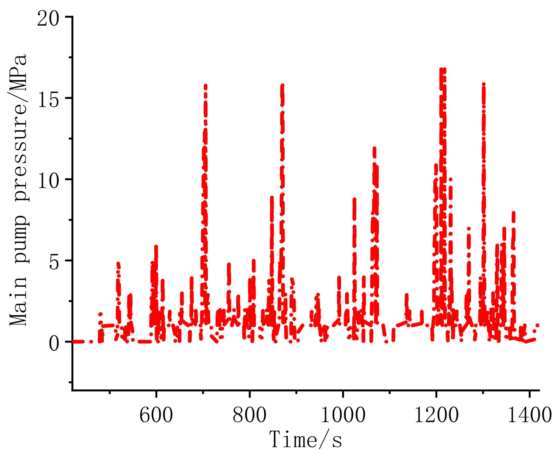
This paper mainly studied the upper working devices of the loader. Therefore, the traveling parts were not taken into consideration. The pressure curve of the main pump for upper devices of a loader in the working process is given in
Figure 2. As can be seen, the load pressure fluctuates greatly in the shoveling process. Therefore, to improve the energy saving and ensure the controllability of the system, efficient matching of flow and pressure of hydraulic system through power train system is crucial.
3. System Scheme
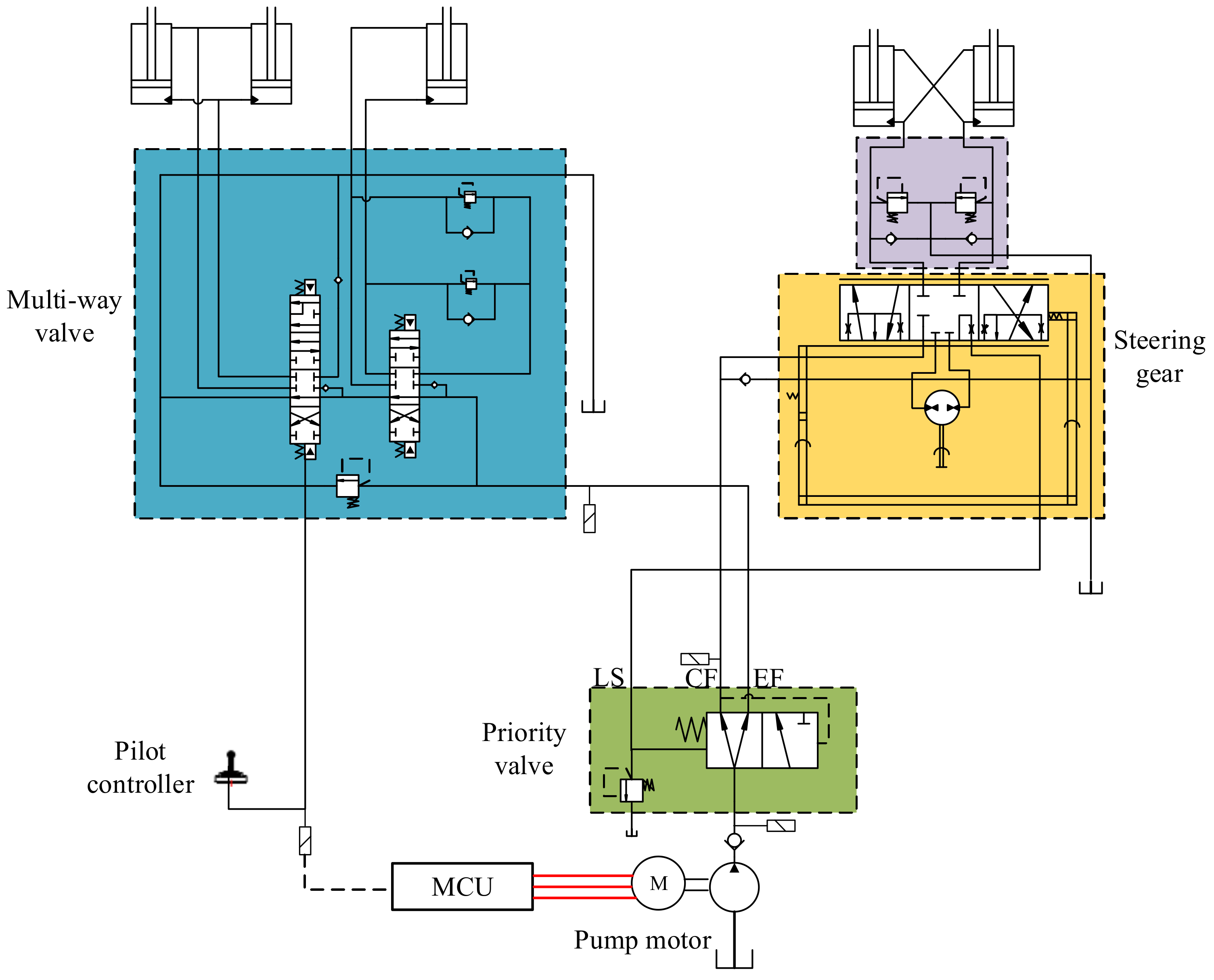
The traditional electric loader only uses the electric motor to replace the engine. The constant speed control of the electric motor is employed to drive the quantitative hydraulic pump. The overflow losses and throttling losses are severe. The positive flow system uses the pilot handle to actively control the pump oil flow and the opening area of the main valve core for the flow matching of the actuator. However, the traditional positive flow system regulates the pump oil flow through the variable displacement of the hydraulic pump, which has the disadvantage of slow response, and cannot adapt effectively to the fast variation of load. Therefore, by using the speed regulation characteristic and the high frequency response of the electric motor, a positive flow system based on variable speed control for a quantitative hydraulic pump is proposed. The schematic diagram of the system is given in
Figure 3.
The positive flow system is composed by a multi-way valve, a steering system, pilot controllers, and a priority valve. The priority valve system is used to ensure the priority control of the steering system when the steering system and hydraulic actuators act at the same time. In priority valve, the LS signal fed back from steering system is a load-sensing signal to control the priority valve. CF is a main oil channel to the steering system. EF is a main oil channel to the multi-way valve. The opening of the multi-way valve is controlled by the pilot handle, and the electric motor speed is controlled by the pilot pressure as well to achieve the flow matching.
To further analyze the stability of the system, the modeling of the system was studied. The schematic diagram of the system is simplified as
Figure 4.
Before mathematic modeling, some assumptions were made as follows.
- (1)
The inlet pressure of the hydraulic pump is zero. The back pressure of the rod cavity of the hydraulic cylinder is ignored. The return oil pressure is zero. The oil tank pressure is zero.
- (2)
The system safety valve does not overflow. The leakage of the safety valve is ignored.
For convenience of analysis, only the extension movement of the oil cylinder is considered. The electric motor dynamic response equation can be regarded as a section of inertia link and expressed as
The transfer function of Equation (1) can be deduced as
The pressure flow equation of the hydraulic pump can be modeled as
The pressure flow equation of the throttle valve can be expressed as
The flow continuity equation of throttle valve can be given as
The force balance equation of the cylinder can be expressed as
By taking Laplace transform for Equations (5) and (6), combined with Equations (2)–(4), the transfer function of the system can be obtained as
Through Equation (7), the secular equation can be obtained as
The Routh array of the proposed system can be given as
because in the above Routh array,
βe << 1.
V2m > 1. Therefore,
kg1 > 1. Meanwhile,
m > 1,
m2 +
Dm −
bL > 1, therefore,
kg1 (
m2 +
Dm −
bL) > 1. Besides,
bL and
A12 are both far smaller than 1,
bL −
A12 − 1 ≈ 1. Therefore, the following inequation can be deduced.
Through Equation (9), the following inequation can be obtained.
since the parameters in the closed-loop transfer function are positive. Meanwhile, the coefficients of the secular equation are positive as well. Furthermore, all the terms in the first column of the Routh array are positive. Therefore, the closed-loop control system is stable.
4. Control Strategy
4.1. Characteristics of Power Train System
In order to ensure the high efficiency of the positive flow system, the characteristics of the power train system of the system were analyzed.
- (1)
Permanent magnet synchronous motor (PMSM) characteristics analysis
The efficiency map of a PMSM is given in
Figure 5. It can be seen that the electric motor efficiency was maintained between 90~97% in most of the working area (more than 80%). When the electric motor speed was distributed in 1500~3000 rpm, the electric motor efficiency was about 94~97%. The highest efficiency was 97% when the motor torque was about 100 Nm.
- (2)
Hydraulic pump efficiency analysis
The efficiency curve of an internal gear pump used for the electric loader is given in
Figure 6. It can be seen that when the system pressure was greater than 10 MPa, the total efficiency of the pump was about 90%. The volumetric efficiency was always larger than 90%. According to the pressure curve shown in
Figure 2, the rated pressure of the hydraulic system was about 10 MPa, and the maximum pressure could reach about 16.5 MPa. In this system pressure range, the efficiency of the hydraulic pump could be about 90%, which is distributed in the high-efficiency area.
4.2. Control Strategy
- (1)
Positive flow system for the electric loader scheme
The positive flow system of the loader is mainly composed of a control system, a power train system, and actuators. The control system consists of a vehicle control unit (VCU), an electric motor controller, a pilot handle, etc. The power train system is composed of an electric motor and a hydraulic pump. The working devices are mainly hydraulic cylinders. The basic framework of the positive flow system is shown in
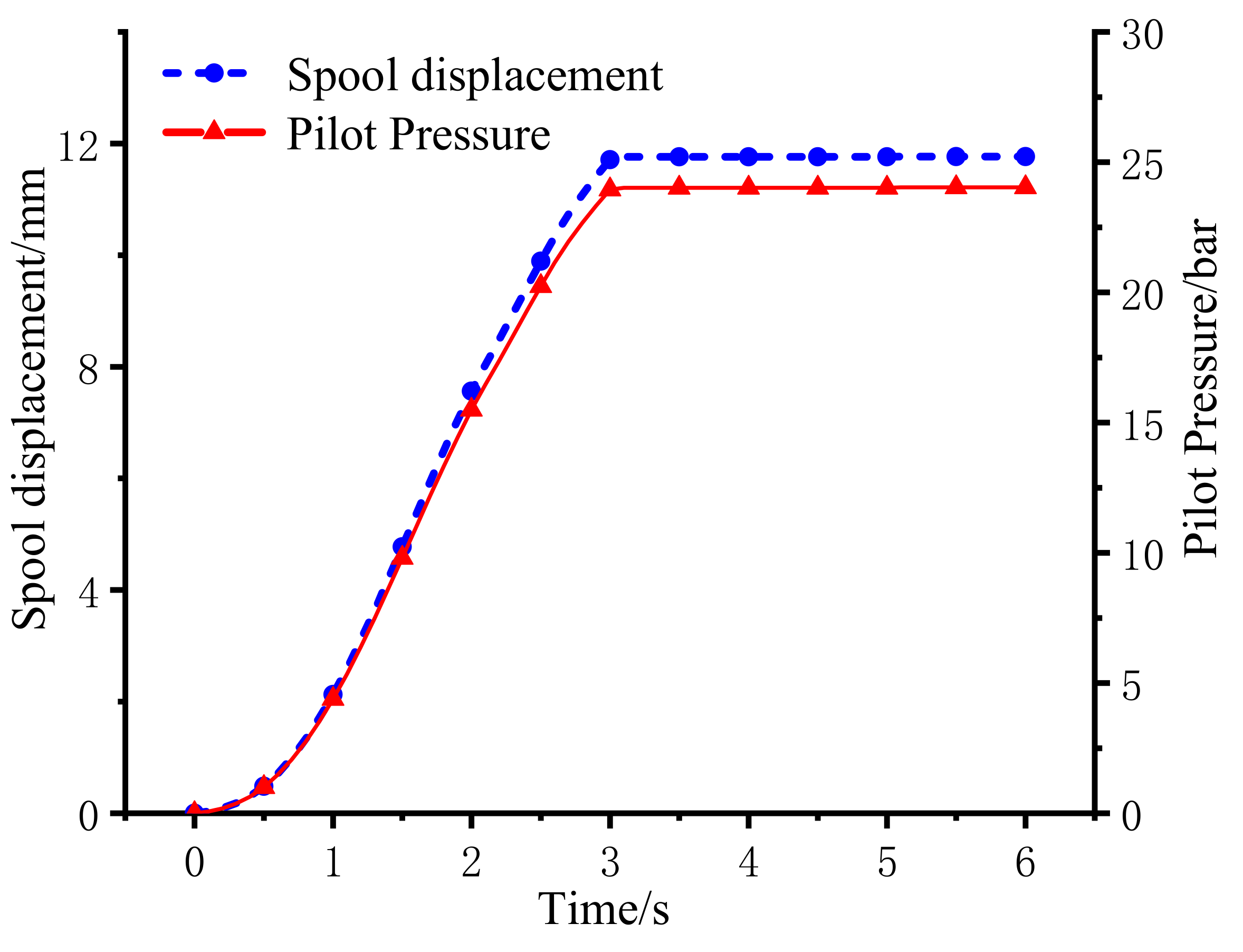
Figure 7. The pilot handle controls the opening area of the multi-way valve. The relationship curve between the pilot pressure and the opening of the main valve core is shown in
Figure 8. Meanwhile, by establishing a positive correlation between the pilot pressure and the electric motor speed, the larger the opening of the multi-channel valve, the higher the electric motor speed.
- (2)
Control strategy of the positive flow system
The opening area of the main valve core is directly proportional to the demand flow of the system. According to the opening area of the valve core, the demand flow of the system can be deduced as
The maximum speed in the high-efficiency area of the electric motor was chosen for the calculation basis of system maximum flow. Combined with the displacement of the pump, the system maximum flow can be calculated according to Equation (10).
The opening area of the valve core depends on the pilot pressure of the system. The open area of the main valve core can be expressed as
The working speed of electric motor can be calculated according to the demand flow of the system and expressed as
According to the above analysis, the basic control flow chart of the positive flow system is given in
Figure 9. Firstly, the pilot pressure is generated through the action of the pilot handle, which is used to push the main spool of the multi-way valve. Secondly, the demand flow of the system is calculated according to the valve core opening. Then, the target speed of the motor is calculated through the demand flow. Finally, the VCU sends a request speed command to the electric motor controller by detecting the pilot pressure, and updates the request value in real time according to the change of pilot pressure so as to control the output flow of the main pump. The output flow of the pump depends entirely on the action amplitude of the pilot handle so as to realize flow matching.
5. Simulation Research
In order to verify the feasibility of the positive flow system and the control strategy, a 1.6 t loader was taken for study. The simulation model of the system was built in AMESim. The system model is shown in
Figure 10. The key parameters of the system are shown in
Table 1. In order to compare the advantages of the proposed scheme over the traditional constant speed system, the constant speed model was also established.
- (1)
System control performance analysis
The curves of the displacement and the speed of a boom cylinder are given in
Figure 11. It can be found that the cylinder moves as required according to the target signal. The relationship curve between pilot pressure and the electric motor speed are given in
Figure 12. During the operation of the pilot handle, the electric motor speed varied with the change of the pilot pressure, which met the control requirements. The electric motor can respond quickly according to the change of the pilot pressure to ensure the controllability of the system.
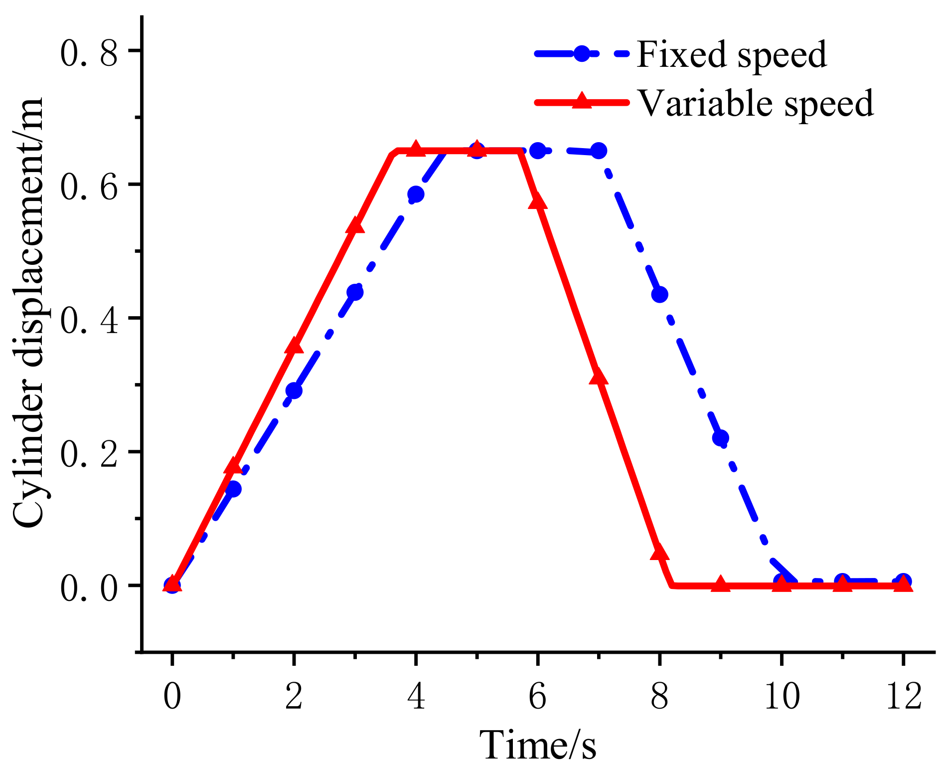
The displacement curves of a cylinder in the variable speed system and the constant speed system are shown in
Figure 13, respectively. It can be seen that the speed characteristics of the cylinder in the variable speed system was significantly faster than that in the constant speed system.
- (2)
System energy saving analysis
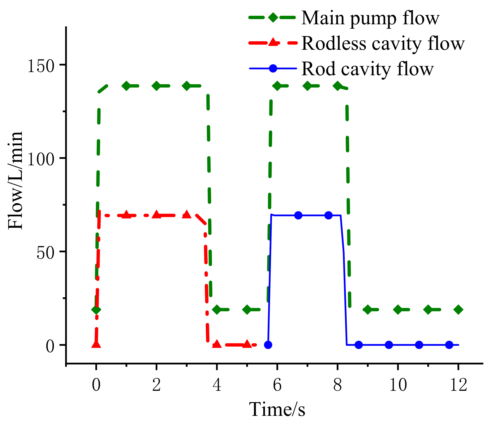
The relationship between the output flow of the main pump and the flow of the rodless chamber of the cylinder is given in
Figure 14. It can be seen that the output flow of the main pump was exactly twice the input of the cylinder due to two boom cylinders being employed. Oil supply according to the requirement can be achieved.
Displacement curves of cylinder simulating boom lifting and lowering in the constant speed system and the variable speed system are shown in
Figure 15. In 0~3.7 s, the boom lifting action was simulated. In 3.8~7.8 s the lifting action was maintained. In 7.9~10.3 s, boom lowering action was simulated. The power output curves of the main pump of the constant speed system and the variable speed systems under the same working conditions are given in
Figure 16. When the output of the pilot handle was zero, the hydraulic pump stopped working. In the constant speed system, the hydraulic pump will always output a constant flow, which leads to the overflow loss of the system. The calculation shows that the output power of the variable speed system was reduced by 22.4% compared with the constant speed system under this working condition.
6. Experiment Research
Further, experimental research was carried out. The schematic diagram and physical diagram of the experimental platform are shown in
Figure 17 and
Figure 18. In this system, a Li-ion battery was employed. A traveling electric motor and a hydraulic pump electric motor were used, respectively. A high-voltage management unit was used to realize power distribution. A VCU was used to collect the signals of the pilot handle and to control the electric motors. The system parameters are shown in
Table 1.
Firstly, the relationship between electric motor speed and pilot pressure was verified. When a step signal of the pilot pressure was input, the electric motor speed changed with the pilot pressure given in
Figure 19. It can be seen that from 560–600 ms, the pilot pressure increased from 0–1.7 MPa, and the electric motor speed also increased from 300–2200 rpm. The electric motor speed response curve when the pilot pressure ramp signal was input is given
Figure 20. As can be seen, the pilot pressure of system rose from 0–1.9 MPa between 23 and 27 s. At the same time, the electric motor speed increased from 300 rpm at 23 s to 2200 rpm at 26.5 s. Therefore, the variable-speed positive flow system can effectively follow the step input and the ramp input.
Further, the energy saving characteristics of the system were studied. Because there was no flow sensor installed in the test prototype, the flow of the pump could not be detected directly. While, the hydraulic pump was driven by the electric motor to supply oil to the system. Therefore, the energy saving characteristic was studied by calculating the energy consumption of the electric motor indirectly.
For comparison, the energy efficiency characteristics of the constant speed system were also analyzed. The same actions were applied to these two different systems. The cylinder displacement curves are shown in
Figure 21. Due to the manual operation for the pilot handle, there was a slight difference between the rising and falling speed of the two systems. However, this does not affect the analysis of the energy saving of the control strategy. It can be seen that the rising time of each system was about 9000 ms and the falling time was about 10,000 ms.
The electric motor output power comparison curves of the positive flow system based on the variable speed and the constant speed are given in
Figure 22, respectively.
It can be found that there was little difference in the electric motor output power of the two systems during boom rising or falling. The main difference happened when the boom moved to the maximum displacement and the pilot handle did not act. In order to obtain the specific energy consumed, integration for data in was carried out and is shown in
Figure 22. Among them, the energy consumed by the electric motor in the constant speed system was 472.846 kJ. While, the energy consumed by the electric motor in the system based on variable speed control was 351.010 kJ. Compared with the constant flow system, the energy consumption of the proposed system was reduced by 121.836 kJ. The energy saving was improved by 25.77% in one cycle of the boom cylinder rising and falling.
7. Conclusions
The electrification of the loader can effectively reduce the emission and improve the energy efficiency. However, the existing electric loader only uses the electric motor to replace the engine and simulate the working mode of the constant speed of the engine, resulting in the inability to maximize the control performance and the energy efficiency of the system.
In this paper, a positive flow system based on electric motor variable speed control was proposed. The relationships among the pilot pressure, the main valve opening, and the electric motor speed were established for flow matching. Simulation and experimental research were carried out. The results showed that the flow matching realized by the variable speed control of the motor could supply the flow according to the action demand of the actuator. The overflow loss of the system could be reduced to a great extent. The energy saving was improved by 25.77% in one cycle of the boom cylinder rising and falling. Besides, the proposed system had a faster response than the traditional system.
Author Contributions
Q.C. proposed the idea of constant power control strategy. T.L. developed the structure and working mode. S.C. wrote the paper and checked and edited the paper. X.L. analyzed the data. All authors have read and agreed to the published version of the manuscript.
Funding
The authors acknowledge the support of National Key Research and Development program (2020YFB2009900), National Natural Science Foundation of China (51905180), Fujian University industry university research joint innovation project plan (2022H6007), Fuxiaquan national independent innovation demonstration zone system innovation platform (3502ZCQXT202002), Natural Science Foundation of Fujian Province (2021J01295)). This work also has been supported by Hitachi Construction Machinery Co., Ltd.
Institutional Review Board Statement
Not applicable.
Informed Consent Statement
Not applicable.
Conflicts of Interest
The authors declare no conflict of interest.
Abbreviations
| PMSM | Permanent magnet synchronous motor | |
| MCU | Motor Controller Unit | |
| VCU | Vehicle Control Unit | |
| BMS | Battery management system | |
| DCDC | Direct current to dirrect current | |
| CAN | Controller Area Network | |
| Nomenclature | |
| τ1 | Constant value of time response of electric motor | s |
| n | Electric motor speed | rpm |
| n* | Electric motor target speed | rpm |
| G1(s) | Transfer function of electric motor | null |
| qp | Output flow of hydraulic pump | L/min |
| D | Displacement of hydraulic pump | cc/r |
| Cp | Leakage coefficient of hydraulic pump | null |
| A1 | Area of rodless cavity of hydraulic cylinder | m2 |
| v | Velocity of cylinder | m/s |
| βe | Effective elastic modulus of oil | MPa |
| Cc | Leakage coefficient of hydraulic cylinder | null |
| V2 | Volume of the cavity between the rodless cavity of the hydraulic cylinder and the throttle valve | L |
| m | Equivalent mass of hydraulic cylinder piston | kg |
| bL | Hydraulic cylinder piston and load viscous damping | N/m/s |
| F | Force of load | N |
| Q | the demand flow of the system | L/min |
| a | the relationship coefficient between valve core opening area and demand flow | null |
| k | open area of main valve core | m2 |
| b | relationship coefficient between pilot pressure and main core opening area | null |
| Pp | Pilot pressure | bar |
| V | the displacement of quantitative pump | cc/r |
| ηr | the volume efficiency of the pump | null |
References
- Lin, T.; Lin, Y.; Ren, H.; Chen, H.; Chen, Q.; Li, Z. Development and key technologies of pure electric construction machinery. Renew. Sustain. Energy Rev. 2020, 132, 110080. [Google Scholar] [CrossRef]
- Gao, F.; Pan, S. Negative flow control model and experimental study. Chin. J. Mech. Eng. 2005, 41, 5. [Google Scholar] [CrossRef]
- Sugimura, K.; Murrenhoff, H. Hybrid Load Sensing– Displacement Controlled Archtecture for Excavators. In Proceedings of the 14th Scandinavian International Conference on Fluid Power, Tampere, Finland, 20–22 May 2015; pp. 20–22. [Google Scholar]
- Ding, R.; Xu, B.; Zhang, J.; Cheng, M. Self-tuning pressure-feedback control by pole placement for vibration reduction of excavator with independent metering fluid power system. Mech. Syst. Signal Processing 2017, 92, 86–106. [Google Scholar] [CrossRef]
- Gao, F.; Wang, S.; Gao, J. Automatic control method research on pendulum speed of roadheader’s cutting arm. In Proceedings of the Mechanic Automation and Control Engineering (MACE), Mongolia, China, 15–17 July 2011; pp. 4789–4791. [Google Scholar]
- Wang, Q. Research on key technology of oil-electric hybrid excavator. J. Mech. Eng. 2013, 49, 7. [Google Scholar] [CrossRef]
- Wen, Q.; Wang, F.; Xu, B.; Sun, Z. Improving the Fuel Efficiency of Compact Wheel Loader With a Series Hydraulic Hybrid Powertrain. IEEE Trans. Veh. Technol. 2020, 69, 10700–10709. [Google Scholar] [CrossRef]
- Li, P.Y.; Siefert, J.; Bigelow, D. A Hybrid Hydraulic-Electric Architecture (HHEA) for High Power Off-Road Mobile Machines. In Proceedings of the Fluid Power Systems Technology, Longboat Key, FL, USA, 7–9 October 2019; Volume 59339, p. V001T01A011. [Google Scholar]
- Mocera, F. A Model-Based Design Approach for a Parallel Hybrid Electric Tractor Energy Management Strategy Using Hardware in the Loop Technique. Vehicles 2020, 3, 1–19. [Google Scholar] [CrossRef]
- Lin, T.; Chen, Q.; Fu, S. Electric Excavator; China Machine Press: Beijing, China, 2020. [Google Scholar]
- Paraszczak, J.; Laflamme, M.; Fytas, K. Electric load-haul-dump machines: Real alternative for diesels? CIM J. 2013, 4, 13–19. [Google Scholar]
- Zhou, H.; Bian, X.; Zhang, Y.; Chun-Sheng, M.; Wang, K. SVPWM control and current hysteresis control of permanent magnet synchronous motor based on Simulink. Equip. Manuf. Technol. 2017, 3, 45–47. [Google Scholar]
- Wang, B. Research on Regenerative Braking and Energy Management Strategy of Dual Energy Source Electric Loader. Master’s Thesis, Changan University, Xian, China, 2020. [Google Scholar]
- Liu, B.; Quan, L.; Ge, L. Research on the performance of hydraulic excavator boom based pressure and flow accordance control with independent metering circuit. ARCHIVE Proc. Inst. Mech. Eng. Part E J. Process Mech. Eng. 2016, 231, 1989–1996. [Google Scholar] [CrossRef]
- Ge, L.; Quan, L.; Zhang, X.; Zhao, B.; Yang, J. Efficiency improvement and evaluation of electric hydraulic excavator with speed and displacement variable pump. Energy Convers. Manag. 2017, 159, 62–71. [Google Scholar] [CrossRef]
- Fu, S.; Chen, Q.; Ren, H.; Lin, T.; Miao, C.; Chen, Q. Potential Energy Recovery System for Electric Heavy Forklift Based on Double Hydraulic Motor-Generators. Appl. Sci. 2020, 10, 3996. [Google Scholar] [CrossRef]
- Liu, Y.; Xiao, B. Research on Modeling and Active Steering Control Algorithm for Electric Forklift Steer-by-Wire System. Int. J. Intell. Syst. Appl. 2016, 8, 70–79. [Google Scholar] [CrossRef] [Green Version]
- Lin, T.; Lin, Y.; Ren, H.; Chen, H.; Li, Z.; Chen, Q. A Double Variable Control Load Sensing System for Electric Hydraulic Excavator. Energy 2021, 223, 119999. [Google Scholar] [CrossRef]
- Guo, T.; Lin, T.; Chen, Q.; Ren, H.; Fu, S. Research on Constant Power Control Strategy of Pure Electric Excavator. Appl. Sci. 2020, 10, 7599. [Google Scholar] [CrossRef]
- Fu, S.; Li, Z.; Lin, T.; Chen, Q.; Ren, H. A Positive Flow Control System for Electric Excavators Based on Variable Speed Control. Appl. Sci. 2020, 10, 4826. [Google Scholar] [CrossRef]
Figure 1.
Typical working conditions of loaders.
Figure 1.
Typical working conditions of loaders.
Figure 2.
Pressure curve of the main pump in the loader.
Figure 2.
Pressure curve of the main pump in the loader.
Figure 3.
Schematic diagram of the positive flow system based on the variable speed and quantitative pump.
Figure 3.
Schematic diagram of the positive flow system based on the variable speed and quantitative pump.
Figure 4.
Simplified schematic diagram of the system.
Figure 4.
Simplified schematic diagram of the system.
Figure 5.
Efficiency map of PMSM.
Figure 5.
Efficiency map of PMSM.
Figure 6.
Efficiency curve of the internal gear pump.
Figure 6.
Efficiency curve of the internal gear pump.
Figure 7.
Framework of the positive flow system.
Figure 7.
Framework of the positive flow system.
Figure 8.
Relationship between the pilot pressure and spool displacement.
Figure 8.
Relationship between the pilot pressure and spool displacement.
Figure 9.
Control flow chart of the positive flow system.
Figure 9.
Control flow chart of the positive flow system.
Figure 10.
AMESim simulation model of the positive flow system based on variable speed.
Figure 10.
AMESim simulation model of the positive flow system based on variable speed.
Figure 11.
Curves of the displacement and speed of the boom cylinder.
Figure 11.
Curves of the displacement and speed of the boom cylinder.
Figure 12.
Relationship curve between the pilot pressure and electric motor speed.
Figure 12.
Relationship curve between the pilot pressure and electric motor speed.
Figure 13.
The displacement curve of the oil cylinder in the fixed and variable speed system.
Figure 13.
The displacement curve of the oil cylinder in the fixed and variable speed system.
Figure 14.
Relationship between the output flow of the main pump and the flow of the rodless chamber of the cylinder.
Figure 14.
Relationship between the output flow of the main pump and the flow of the rodless chamber of the cylinder.
Figure 15.
Displacement curve of the cylinder simulating boom lifting and lowering in the constant/variable speed systems.
Figure 15.
Displacement curve of the cylinder simulating boom lifting and lowering in the constant/variable speed systems.
Figure 16.
Output power curve of main pump under the constant/variable speed systems.
Figure 16.
Output power curve of main pump under the constant/variable speed systems.
Figure 17.
System structure diagram of the pure electric loader.
Figure 17.
System structure diagram of the pure electric loader.
Figure 18.
Test prototype of the 1.6 t pure electric loader.
Figure 18.
Test prototype of the 1.6 t pure electric loader.
Figure 19.
Step response curve of the electric motor speed with pilot pressure.
Figure 19.
Step response curve of the electric motor speed with pilot pressure.
Figure 20.
Ramp response curve of the electric motor speed with pilot pressure.
Figure 20.
Ramp response curve of the electric motor speed with pilot pressure.
Figure 21.
Comparison curve of cylinder displacement under different modes. (a) Cylinder displacement under constant speed; (b) cylinder displacement under variable speed.
Figure 21.
Comparison curve of cylinder displacement under different modes. (a) Cylinder displacement under constant speed; (b) cylinder displacement under variable speed.
Figure 22.
Electric motor power comparison curve under different modes. (a) Power of constant speed control; (b) power of variable speed control.
Figure 22.
Electric motor power comparison curve under different modes. (a) Power of constant speed control; (b) power of variable speed control.
Table 1.
Parameters of the key components.
Table 1.
Parameters of the key components.
| Parameter | Model | Unit |
|---|
| Maximum speed of electric motor | 2400 | r/min |
| Displacement of pump | 63.7 | mL/r |
| Cylinder rod diameter | 50 | mm |
| Cylinder diameter | 90 | mm |
| Maximum pressure | 18 | MPa |
| Maximum pilot pressure | 3 | MPa |
| Publisher’s Note: MDPI stays neutral with regard to jurisdictional claims in published maps and institutional affiliations. |
© 2022 by the authors. Licensee MDPI, Basel, Switzerland. This article is an open access article distributed under the terms and conditions of the Creative Commons Attribution (CC BY) license (https://creativecommons.org/licenses/by/4.0/).


