Article

Extended Reality Application Framework for a Digital-Twin-Based Smart Crane

Department of Mechanical Engineering, Aalto University, 02150 Espoo, Finland
*
Author to whom correspondence should be addressed.
Appl. Sci. 2022, 12(12), 6030; https://doi.org/10.3390/app12126030
Submission received: 6 May 2022 / Revised: 8 June 2022 / Accepted: 11 June 2022 / Published: 14 June 2022

Abstract

:
Industry 4.0 is moving forward under technology upgrades, utilizing information technology to improve the intelligence of the industry, whereas Industry 5.0 is value-driven, aiming to focus on essential societal needs, values, and responsibility. The manufacturing industry is currently moving towards the integration of productivity enhancements and sustainable human employment. Such a transformation has deeply changed the human–machine interaction (HMI), among which digital twin (DT) and extended reality (XR) are two cutting-edge technologies. A manufacturing DT offers an opportunity to simulate, monitor, and optimize the machine. In the meantime, XR empowers HMI in the industrial field. This paper presents an XR application framework for DT-based services within a manufacturing context. This work aims to develop a technological framework to improve the efficiency of the XR application development and the usability of the XR-based HMI systems. We first introduce four layers of the framework, including the perception layer with the physical machine and its ROS-based simulation model, the machine communication layer, the network layer containing three kinds of communication middleware, and the Unity-based service layer creating XR-based digital applications. Subsequently, we conduct the responsiveness test for the framework and describe several XR industrial applications for a DT-based smart crane. Finally, we highlight the research challenges and potential issues that should be further addressed by analyzing the performance of the whole framework.

1. Introduction

The breakthrough in transformative information technologies has meant that the world stands on the threshold of the fourth industrial revolution, or Industry 4.0 [1]. Industry 4.0 is driven by digital technological advances, which have led to fundamental and sustainable digital upgrades in the manufacturing field [2]. Industry 5.0, meanwhile, is regarded as the next industrial revolution, and it will emerge when intelligent devices, intelligence systems, and intelligent automation are fully integrated with the physical world [3,4]. The aim of Industry 5.0 is to leverage the creativity of human experts in cooperation with smart machines, in which digital twin (DT) and extended reality (XR) could empower humans with access to critical insight as well as control over diverse machines, systems, and processes [4].
On the one hand, DT realizes real-time and continuous synchronization of data transmission between real products or systems and virtual mathematical models, which represent the state of the real twin and provide data analytics, simulation, and optimization. It can offer significant value for the improvement of the user experience. On the other hand, XR, as an umbrella term for virtual reality (VR), augmented reality (AR), and mixed reality (MR), can improve the human–machine interaction by combining the virtual and physical worlds.
However, there is a lack of an established technical guideline to support such integration of XR services into DT systems in the manufacturing field. In order to facilitate such integration, this research aims at creating a systematic XR application development framework for the DT-based machine to provide highly supportive HMIs. The framework was derived based on a DT-based overhead crane and validated through several use cases.

1.1. Industry 4.0 and Industry 5.0

The term Industry 4.0 originated in 2011 by a German initiative of the federal government with academic associations and commercial enterprises [5] and was defined as a means to achieve flexible production of high-quality personalized products at mass efficiency through the integration of CPS (Cyber–Physical Systems) into production [6]. Globally, many countries have created similar local strategy initiatives, for instance, Industrial Internet Consortium (USA), Made in China 2025 (China), La Nouvelle France Industrielle (France), Society 5.0 (Japan), Towards Industry 4.0 (Brazil), to list a few [2,7]. Hence, Industry 4.0 has since become a globally adopted term and the focus of significant research efforts [2] with Smart Factories being among the key initiatives. Industry 4.0 is identified as four-dimensional front-end technology: Smart Manufacturing, Smart Products, Smart Supply Chain, and Smart Working, and relies on four elemental base technologies: IoT, cloud services, big data, and analytics [8]. When it comes to economic indicators, Industry 4.0 has decreased production costs by 10–30%, logistic costs by 10–30%, and quality management costs by 10–20% [9]. Industry 4.0 is technology-driven [2], providing technological pushes and solutions.
In the meantime, Industry 5.0, regarded as the next industrial revolution, aims to leverage the creativity of human experts in collaboration with smart machines to obtain user-preferred manufacturing solutions [4]. Industry 5.0 recognizes the power of industry to achieve societal goals and to support long-term service to humanity [10]. It involves the combination of advanced technologies and human common life, with the return of the man to the “Centre of the Universe” [1], taking advantage of humans’ decision-making capability to harmonize the working conditions and efficiency of humans and machines in a consistent manner [4].
The aim of Industry 4.0 is to lessen the participation of human operators and to stress automation systems, whereas Industry 5.0 aims to achieve maximum benefits through the HMI [11]. Therefore, advanced HMI solutions between more intelligent machinery and the productive abilities of human beings are required [12]. Among those, digital twin [13,14] is considered one of the key technologies to enhance HMI through advanced modeling techniques. In parallel, the “Age of Augmentation” has arrived, in which humans and machines work symbiotically to leverage XR technologies, enhancing the operator’s cognitive and interaction capabilities [10].

1.2. Digital Twin

The general concept of a digital twin refers to a new simulation means based on CPS and IoT providing a real-time synchronization with the production systems [15]. The DT-coupled big data analysis and Artificial Intelligence (AI) implements real-time monitoring, decision-making, and failure prediction, enhancing the cooperation between an operator and the smart machine [16]. “A conceptual idea” of the digital twin was first proposed by Grieves in 2002 for product lifecycle management (PLM), and it was called “Conceptual Ideal for Product Lifecycle Management” [17]. The concept contained three components: the virtual and real systems, as well as constant information exchange between both systems. Through real-time data communication between the physical world and its digital counterpart, DT was expected to play a role throughout a product’s lifecycle. In 2010, the term “digital twin” was adopted by the National Aeronautical Space Administration (NASA), which defined it as follows: “A digital twin is an integrated multiphysics, multiscale, probabilistic simulation of an as-built vehicle or system that uses the best available physical models, sensor updates, fleet history, etc., to mirror the life of its corresponding flying twin” [18].
Recently, DT has grown into an increasingly wide variety of domains with different applications and objectives [15]. In cases, DT can be used for simulation and modeling of physical assets, systems, or processes [16,19]. Furthermore, DT can help to monitor the production line performance and balancing by the analyses of production line performance parameters [20]. Moreover, DT’s processes can be fully integrated into the various stages of build construction, from physical construction site entity modeling to virtual and real interaction modeling, to improve the efficiency of construction efficiency [21]. Additionally, DT can be adopted for predictive maintenance or design improvement through monitoring and evaluation, e.g., the inefficiency or stress load of machinery [22,23]. In others, DT can be coupled with XR technologies to support modeling, simulation, and evaluation of manufacturing systems [24,25]. In addition, to contain and handle meta-level DTs, an open-source, Git-based Digital Twin Web server Twinbase was provided [26].
A feature-based DT framework proposed in [27] suggested nine technical features and their integration through a central data link. Computation, coupling, identifiers, security, data storage, user interfaces, simulation models, analysis, and artificial intelligence, marked by the functional requirements in implementing DTs in the context of Industry 4.0. Among these elements, user interfaces allow operators to interact with DTs, thus creating HMI as a central building block of DT implementations.

1.3. Industrial XR Applications

Currently, the manufacturing system is becoming more agile and flexible, more able to achieve small-scale production in an economically sustainable way [28]. Meanwhile, the integration of human operators into production, or HMI, is considered a key factor facing the increasing complexity of the manufacturing context [29]. Smart factory HMI functions as a wrapper for visualization, aggregation, and analysis to assure humans realize their full potential and adopt the role of strategic decision-maker and flexible problem-solver [30]. With modern production strategies, where systems and processes are self-optimized, operators are expected to perceive and engage with aggregate, prepared, and nicely presented HMI to monitor and intervene within processes (usually through physical interfaces).
Mobile devices have been widely adopted in manufacturing and production processes, including overhead displays, tablets, and smartphones, with multi-modal (gaze, voice, gesture, tactile, and haptic) or multi-touch interaction capabilities. XR is acknowledged as having a vital role in enabling different HMI applications [4]. Representing AR, VR, and MR in the reality–virtuality continuum [30], XR technologies refer to the combined environment of all real and virtual assets where the human interacts with a machine, and are therefore expected to bring transformation to manufacturing. The development of XR technologies has brought many research directions, including industrial model preparation, information integration, data visualization, and XR application development. Dammann et al. [31] provided a structure for the geometry preparation automation process, which simplified the integration of XR applications into product development. Bellalouna [32] proposed a digital transformation of engineering processes using VR technology. Arjun et al. [33] presented a smart sensor dashboard of smart manufacturing, which can be used to design VR environments with interactive graphs. In addition, the implementation of XR technology can provide a convenient and natural human–machine interface. Burghardt et al. [34] presented a method of programming robots using virtual reality and digital twins. He et al. [35] proposed a mobile augmented reality remote monitoring system to help operators with low knowledge.
When it comes to the crane, the industry has witnessed diverse XR applications for it. A conceptual speech-based HMI equipped with AR and interactive systems was proposed in [36] for controlling mobile cranes. An approach integrating 4D building information modeling and AR proposed in [37], provided users with real-time navigation for tower crane lifting operation with enhanced safety and efficiency. An assistance system for mobile cranes leveraging AR was developed in [38] to provide safety-related information for operators. An interactive virtual reality system integrated with a database was developed to evaluate mobile crane lift operations in [39]. However, these cases were developed according to the specific requirements, lacking a general framework for the development of XR applications. On the other hand, the data flow of those apps is limited to one direction, which is hardly used for a DT-based machine.

1.4. Research on XR Development Framework

Some literature has researched the XR development framework. Gong et al. [40] provided a framework for XR system development in manufacturing, which consisted of five iterative phases: (1) requirements analysis, (2) solution selection, (3) data preparation, (4) system implementation, and (5) system evaluation. The proposed framework focused mainly on the methodology of product development. Catalano et al. [41] put forward a DT-based conceptual framework for enabling XR applications. However, the framework was too conceptual and lacked implementing details. Pereira et al. [42] proposed an XR framework for remote collaborative interaction in the virtual environment. Tu et al. [43] provided a HoloLens 1-based MR interface solution focusing on data visualization and control of a DT-based crane, enabled by Vuforia-based spatial registration and GraphQL-based communication. However, the MR application development framework based on HoloLens 1 and MRTK is obsolete, because the latest platform of Microsoft HoloLens 2 supports OpenXR that is integrated with the encapsulated registration and visualization modules.
To sum up, an industrial XR application development framework for the DT-based machine is needed to enhance the reusability of the virtual assets and data interaction, as well as increase the XR application development efficiency.

1.5. Research Gap and Our Contribution

Although the benefits associated with the integration of the XR services with the DT systems are promising, the relevant research has not yet provided a comprehensive guideline for industrial XR application developers. Therefore, more effort is needed to provide an XR application development framework for the DT-based machine. In particular, one of the main concerns is that the framework should guarantee wide generality and high efficiency.
This paper is based on the master thesis of the first author [44]. The thesis provided a VR application development framework targeting the ROS-based machine. An interactive Virtual environment was established, integrating with the communication protocol between ROS and Unity. However, there were several limitations of the previous work:
  • The control unit of the simulated model was set up by the ROS MoveIt package, which was not compliant with the PLC-based machine.
  • The WebSocket protocol was used to connect the simulated model to the applications in Unity in the local network, which was not consistent with the practical industrial scenario.
  • The whole framework was established under the simulated and virtual environment, lacking an interface with the physical machine.
The main contributions in this paper, handling the limitations of previous research on the VR application framework and existing XR development framework solutions, are:
  • Providing an XR application technological framework for the DT-based machine (see Figure 1).
  • Presenting software integration process for XR applications.
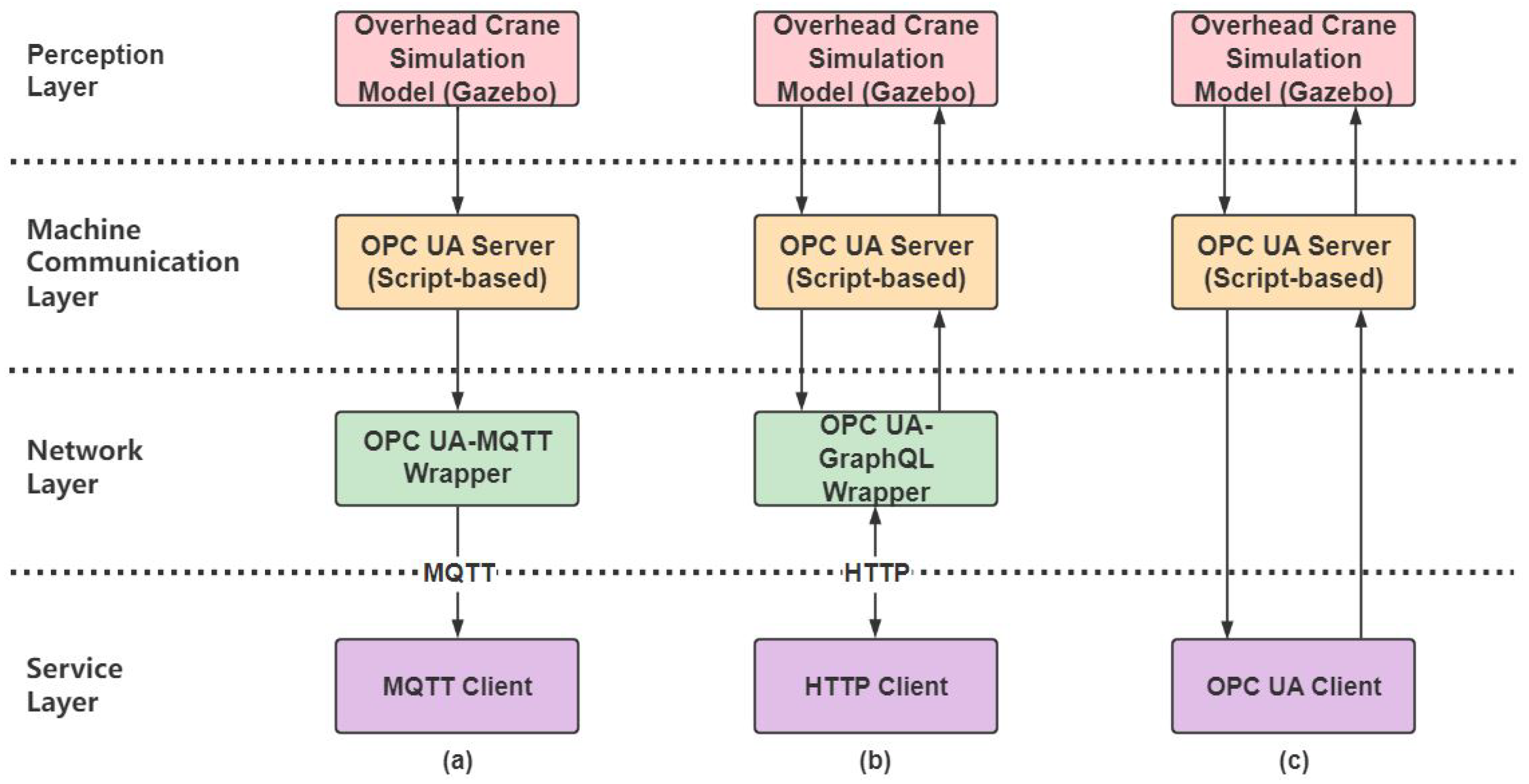
  • Developing several XR applications based on the framework leveraging different communication middleware, including OPC UA-MQTT wrapper, OPC UA-GraphQL wrapper, and OPC UA-Unity client.

2. Materials and Methods

Figure 1 displays the development framework: the perception layer involved the DT-based “Ilmatar” crane and its corresponding simulation platform Gazebo in ROS 2.0. The machine communication layer mainly introduced the communication bridge between the simulation platform ROS 2.0 and the OPC UA server. For the network layer, three communication middleware were developed aiming for different application scenarios, from the lab environment to the actual industrial environment. Additionally, the service layer brought the procedures of hardware and software integration and XR environment setup. In addition to the XR development framework, this section introduces the measurement setup for testing the responsiveness of the communication middleware.

2.1. “Ilmatar” Crane

“Ilmatar” is the name of an industrial overhead crane installed in the Aalto Industrial Internet Campus (AIIC) in late 2016. It is a Konecranes CXT family crane with several smart features, such as target positioning, sway control, load floating, and snag prevention [45]. Figure 2 illustrates the main components of the crane. The crane contains three main moving subsystems, the bridge for moving forward and backward through Axis Z, the trolley for moving left and right through Axis X, and the hoist for moving up and down with the hook block through Axis Y. Table 1 displays the basic functional properties of the crane, which keeps consistency with the model in ROS and the model in Gazebo.
In addition, the crane is equipped with a Siemens PLC (Programmable Logic Controller) that handles crane sensors and control data, and the PLCs are linked to an OPC UA (Open Platform Communication Unified Architecture) server to provide external access to the crane data. Meanwhile, the crane is connected to the Internet, which can send data to a third partly IoT platform, “MindSphere” by Siemens, via a cloud vendor.
The crane is mainly used for research, co-innovation, and education in the university lab environment instead of regular high-load and high-frequency production line tasks [45]. The crane is equipped with various intelligent sensors and integrated with DTs based on the previous work by Autiosalo et al. [46]. Many digital assets were developed, such as OSEMA (Open Sensor Manager) [47], OPC UA-GraphQL Wrapper, and DT Core, making the “Ilmatar” crane a suitable target for DT-based research.

2.2. Simulation Model

Physical-field-based simulation model represents the complicated working condition of a machine, providing an overall picture of performance even in the face of unprecedented conditions, thus realizing the potential of DTs. DT always contains a simulation model that not only reflects how the machine works but also predicts how the machine will perform [16]. Furthermore, the simulation model enables the reflection of the real-time states of the operating machine [48]. Additionally, compared to numerical and analytical models, simulation models are most often applied in Industry 4.0 [49]. Considering the research requirements, the characteristics of the simulation model shall be high compatibility, scalability, interoperability, and open source.
ROS (Robot Operating System) originated from the Personal Robots Programs, a collaboration between the AI laboratory at Stanford University and robot technology company Willow Garage in 2007 [50], aiming to improve the reusability and modularity of the code in the robotics field. ROS is a distributed framework of processes, enabling loosely coupled network connection of the modules from package to package. To simplify the robot development, ROS 1.0 [51] designs a series of communication mechanisms, including asynchronous streaming of data over a topic, RPC (synchronous Remote Procedure Call) over service, continuous response over action, and a parameterization server to store design parameters. The latest version of ROS 1.0 was released in 2020 as Noetic and the EOL (End of Life) date is 2025. However, in ROS 1.0, all the components and functions are connected through one center node “ROS Master”, so once the ROS Master is down, the whole system communication will be abnormal, which is a hidden danger for industrial use. To solve this fatal defect, ROS 2.0 was launched in 2015. In the OS (Operation System) layer, the new support platforms involve Windows, Mac, and RTOS (Real Time Operating System). Meanwhile, in the middleware layer, it adapts the message distributed mechanism based on DDS (Data Distribution Service) to decentralize ROS Master [52], which enhances real-time, persistence, and reliability. Gazebo [53] is an open-source and free 3D physical simulation platform designed for ROS, which supports various high-performance physical engines, 3D visualization environments, sensor simulations, TCP/IP transmission, and cloud simulation. Therefore, ROS 2.0 (Foxy version) and Gazebo are selected for the simulation platform in the research.
In our research, the purpose of the ROS-based simulation platform was to validate the feasibility of the architecture and test the middleware performance; therefore, only the bridge and trolley moving parts were developed and simplified in the 3D modeling software Siemens NX according to the comprehensive crane model from Konecranes.
SDF (Simulation Description Format) is designed specifically for Gazebo, which describes everything from the world to the robot in XML (Extensible Markup Language) format [53], while URDF (Unified Robot Description Format) is a format for describing robot structures based on the XML specification. SolidWorks to URDF Exporter, an open-source SolidWorks add-in, allows for the export of Assembles in SolidWorks into a URDF file. Moreover, Gazebo enables conversion from the modified URDF to SDF automatically [53]. Figure 3 illustrates the workflow that converts the 3D model to the URDF file used in Gazebo. Moreover, two virtual IMU (Inertial Measurement Unit) sensors were set up separately, with the bridge and the trolley.

2.3. Machine Communication Layer

OPC UA, published in 2008, is an interoperability standard in the automation industry for the data security exchange, aiming to convert the PLC-specific protocol to the standardized interface and establish a specific protocol for the general real-time read and write functions [54]. Beyond that, it is an independent platform to assure seamless data transmission among equipment from different suppliers. OPC UA [55] is a secured protocol applied on the application layer, while TCP/IP protocol is on the network layer. Furthermore, OPC UA is widely used in the automation field with open-source and cross-platform features. On the physical crane side, the “Ilmatar” crane is equipped with Siemens PLCs integrated with the OPC UA server. Meanwhile, on the simulated crane side, an independent Python-script-based OPC UA server was developed, with all the variables kept in the same format corresponding to the OPC UA server of Siemens PLCs. The machine communication layer established a bidirectional bridge between ROS and OPC UA. The bridge implements the operation of write and read by subscribing the ROS topics, respectively, write concerning the position of the components in the Gazebo to the OPC UA server, read concerning the direction and speed of the components from the OPC UA. The bridge between ROS and OPC UA enables multi-machine collaborative communication [56].

2.4. Network Layer

We developed three kinds of communication middleware in the network layer (Figure 4), the OPC UA-GraphQL wrapper targeting the remote control application, the OPC UA-MQTT wrapper focusing on the remote monitor application, and the general OPC-Unity client. The former two kinds of communication middleware are introduced below in detail. For the latter one, Unity supports C# and JavaScript, but the commonly used python-opcua package cannot be used in Unity. Therefore, we developed the OPC UA client with the UA-.NETStandard in Unity, with the source code published on the GitHub [57].

2.4.1. OPC UA-MQTT Wrapper

MQTT (Message Queuing Telemetry Transport) is a publish/subscribe messaging transport designed for remote devices, especially machine-to-machine (M2M) communication with poor network conditions and limited network bandwidth. Since there is no direct connection between publisher and subscriber under MQTT communication, it is necessary to set up a broker to decouple the message [58].
OPC UA is a robust, secure, and scalable industrial standard communication protocol. MQTT is lightweight and therefore suitable for remote data transmission. Hence, an OPC UA-MQTT wrapper was developed in our research, which can transmit the data from the OPC UA server to the MQTT broker. The OPC UA-MQTT wrapper contains an OPC UA client, an OPC UA-MQTT gateway that transfers data read from the server to the MQTT message format, an MQTT client that sends the data, and an MQTT broker deployed in the open network. The network layer of the monitoring application was realized by the OPC UA-MQTT wrapper. The source code is published as open-source on GitHub [59].

2.4.2. OPC UA-GraphQL Wrapper

OPC UA-GraphQL Wrapper, published on GitHub as an open-source software [60], is the middleware between the client and OPC UA server, which connects to an OPC UA interface to provide it with a GraphQL interface. The wrapper was developed by Hietala as a master’s thesis [61], and used as a part of the communication module for a mixed-reality interface by Tu [43]. OPC UA is one of the most important industrial communication protocols in the automation field. The OPC UA information model is a structured graph composed of nodes and references. Meanwhile, GraphQL is a query language that is advantageous for querying the data of the Graph structure. The combination of OPC UA and GraphQL can provide an understandable and friendly API for the developers. In this work, the OPC UA-GraphQL was used for the remote control use case.

2.5. Hardware Setup

Oculus is leading the customer-based market of the VR headset given its affordable price, portability, and sufficient capability [62]. Oculus Quest 2, released in 2021, is equipped with four infrared cameras that enable location tracking, hand tracking, and pass-through. Its per-eye resolution is 1832 × 1920; the refresh rate is 90 Hz, and the FOV (Field of View) is around 120 . The connection mode of the controller is inside-out tracking.
HoloLens 2 is the latest MR device developed by Microsoft in 2019. It adapts multiple sensors, advanced optics, and holographic processes to blend seamlessly with the environment, sense the spatial orientation of the surrounding unit, track the obstacles, and generate holograms to display information and simulate a virtual world. An Optical see-through display of HoloLens 2 enables the user to view the natural world in full resolution. The FOV of HoloLens 2 is 43 × 29 ; the refresh rate is 60 Hz, and the resolution is 2 K. Compared to HoloLens 1, HoloLens 2 supports OpenXR.
In the professional business-based market, high-resolution and high performance are extensively required by the business customer. Varjo technology released Varjo XR-1 Developer Edition in 2019, which allows engineering, design, and simulation professionals to blend the real world with the virtual world. As the first industrial photorealistic mixed reality headset, it is equipped with two screens, with a per-eye resolution of 1920 × 1080 (micro-OLED) and 1440 × 1600 (AMOLED), 90 Hz refresh rate, and 87 FOV for VR. Additionally, the video see-through display of Varjo XR-1 supports AR function with FOV 82 × 82 . The tracking mode of Varjo XR-1 is outside-in tracking from two extra infrared base stations. Consequently, it has no hand-tracking feature. An additional computer with a thunderbolt card installation is needed to set up Varjo XR-1. Table 2 shows the comparison of the three XR devices used in the research.

2.6. Software Setup

The software setup used several toolkits, packages, and plugins to facilitate the XR environment, namely, model module design, function module design, and communication module design.
Unity: Unity is a leading real-time development platform for creating and operating interactive, real-time 2D, 3D, VR, and AR content. It is cross-platform, supporting more than 20 platforms, e.g., Windows, Android, and iOS. It is time-saving for sharing development assets between different contents. Meanwhile, Unity has abundant external packages to assist professional development. In addition, Unity is free for the non-profit personal developer.
OpenXR: Previously, there was no unified and standard interface between the XR hardware and the XR application. Every hardware had a specific SDK (Software Development Kit) to integrate with the XR application, which increased the development period and maintenance cost for the cross-platform developers. OpenXR, provided by Khronos Group, is a royalty-free, open standard that provides high-performance access to XR platforms and devices [63]. Currently, the developers merely focus on the OpenXR application layer based on the development platform, such as Unity and Unreal, while the device manufacturers concentrate on the OpenXR device layer. OpenXR is compatible with Oculus Quest 2, HoloLens 2, and Varjo XR-1.
XRTK/MRTK: The XRTK (XR Interaction Toolkit) is a component-based interaction system. It provides a framework for the developers to implement the basic functionalities of the XR applications. Meanwhile, the MRTK (Microsoft Mixed Reality Toolkit) provides a set of components and features to accelerate cross-platform MR application development, supporting OpenXR and Microsoft HoloLens 2.
HslCommunication: HslCommunication is an open-source package to solve complex data communication between industrial networks. It can be used among several independent programs, different operation systems, and different IDEs (Integrated Development Environments). In this research, we developed the MQTT client in Unity with the HslCommunication package.
RestSharp API: RestSharp is a comprehensive REST API client library based on the .NET framework. Meanwhile, RestSharp is a lightweight REST API Client library implementing synchronous and asynchronous HTTP calls. RestSharp is used in the communication module of the application layer.
UA-.NETStandard: It is an official OPC UA .NET standard stack from the OPC Foundation. .NET standard ensures all common platforms are available today without extra modification. Given the Unity supporting programming language, the OPC UA-Unity client was developed based on UA-.NETStandard.

2.7. The XR Environment Development

Figure 5 depicts the structure of the service layer. The XR environment development contains three sub-modules, the model module, the function module, and the communication module. The model module determines the generally used models that keep consistency with the DT-based crane. The function module realizes the crane features and AR or VR functions related to the corresponding device. The communication module is responsible for interaction with the network layer on the Unity side.
Model Module: To guarantee the consistency and interoperability of the model in the XR environment, our research provided a standard modeling method, with the crane as a study case. Figure 6 displays the “Ilmatar” crane model in Unity. The method consists of the following three steps.
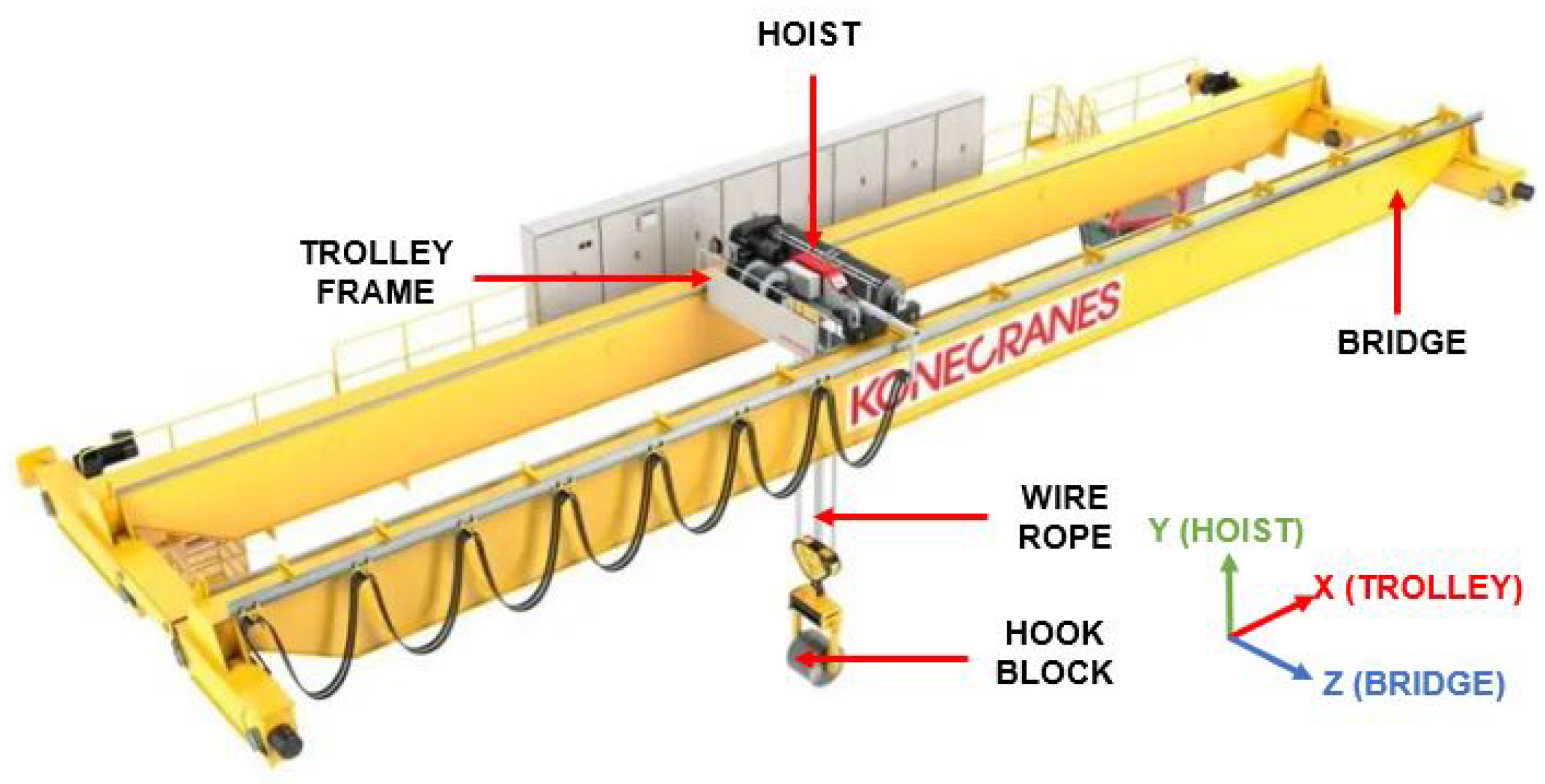
  • Identify the key moving system, and disassemble the corresponding parts in the CAD or original software: The crane was divided into four main moving parts, namely, the bridge, trolley, hoist, and hook block (see Figure 2). In Siemens NX, each moving part was disassembled as an isolated file.
  • Convert to the Unity compatible format: The STP file is the most general format that is compatible with most industrial CAD software, such as AutoCAD, Siemens NX, and SolidWorks. In the meantime, STP is a format for 3D graphics files and supports product model data exchange, which is commonly used as the transition format between the different software. There are two kinds of methods for model import in Unity: one is exporting models as FBX or OBJ format by the specific plugin; the other is directly exporting the model as the corresponding file, such as max or blend, which can be converted automatically by Unity. The former method is suitable for the case in which the model originates from industrial 3D software. In our research, the original model file was exported as STP format, through the specific plugin, and converted to the OBJ format.
  • Set up the coordinate system and establish the parent–child relation of the import parts: There is no coordinate relation for the imported model. The coordinate system should be reestablished in the Unity, as well as the parent–child organization of the components according to the movement relation.
Function Module: The crane features are implemented by the script-based components, including Inching, Snag Prevention, and Micro Speed. Inching provides a way to approach a load destination with great accuracy. It allows the operator to make small inching movements. When the inching feature is activated, the movement will stop after it has traveled the predefined inching distance. The Snag Prevention function will automatically stop the moving crane when the crane hook catches on another object. Micro Speed allows the operator to use the whole joystick movement range while not going over the required maximum speed. The crane features were developed for the VR training application. XR functions, such as VR locomotion, VR object grab, AR hand tracking, and UI interaction, were realized by the component-based toolkit, XRTK, and MRTK.
Communication Module: First of all, it is necessary to define the data format of the model. Table 3 illustrates the definition of data in the XR environment, including the design parameter of the crane, the status data of the running crane, and the data concerning the controller. The design data is from Table 1, describing the constant design parameters. The data is stored as a component in Unity as the constant private value. Later, all the data will be accessed from the DT (Digital Twin) Document. The DT document describes the metadata and features of a single digital twin, which is under development. The document is designed to be used along with a Data Link that connects the features of the digital twin behind a single access point [64]. Then, the status data shows the real-time location of the crane accessed from the network layer. Next, the control data represents the status of the controller, namely the smart feature buttons and the joysticks, used for the data flow between the network layer and the service layer. In the end, for the middleware of the OPC UA-GraphQL wrapper, the communication module established the HTTP connection through the RestSharp API to receive the corresponding data predefined in Table 3.

2.8. Measurement Setup

To evaluate the performance of the XR application development framework, the responsiveness test with three communication middleware was conducted. The measurement setup (see Figure 7) consisted of a desktop hosting the simulation environment in Ubuntu and the XR environment in Windows, a Raspberry Pi 4 Model B 2GB hosting GraphQL interface server, and MQTT mosquitto broker, and a switch providing the local network. The desktop had an Intel i9-10900KF processor and 64 GB RAM.
Figure 8 depicts the data transmission processes based on three communication middleware. For the responsiveness test, the perception layer of the simulated model was deployed in Gazebo running in Ubuntu. We firstly control the simulated crane in Gazebo developed in the perception layer, then through the bridge between ROS and OPC UA, the OPC UA server was able to read data from the Gazebo. For the OPC UA-GraphQL wrapper, the REST Client in Unity requested the data via the GraphQL server running on the Raspberry Pi. Meanwhile, for the OPC UA-MQTT wrapper, the OPC UA-MQTT gateway transferred the OPC UA protocol to the MQTT protocol, and the MQTT client in Unity subscribed to the topic through the Mosquitto broker. In addition, the OPC UA client in Unity set up the connection with the OPC UA server directly.
The OPC UA server recorded the timestamps with python datetime function when it read the data from the simulation environment, and the corresponding client in the XR environment recorded the timestamps with C# DateTime function when it subscribed to the same data. To keep the time consistency of the measurement scale, the OPC UA server and the corresponding client were deployed on the same desktop. Each client subscribed to 200 values during one experiment, and each experiment was conducted 10 times.

3. Results

3.1. The Performance of the Framework

The response times are summarized in Table 4. Each statistical data was from the 2000 pairs of the value recorded by the OPC UA server and the Unity Client. The measurements show that using the OPC UA-MQTT wrapper is significantly faster. Meanwhile, the OPC UA-MQTT wrapper is more stable with the lowest standard deviation. Consider the MQTT client in Unity executed the subscription function to subscribe to the changed data. To implement the identical function, we developed the subscription functions for the REST client and OPC UA client in Unity. The function implementation rate in Unity is influenced mainly by the self-refresh rate of the Unity engine. Therefore, the performance difference between the OPC UA-GraphQL wrapper and the OPC UA client in Unity is relatively small.
In our XR development framework, the development of the communication middleware influences the development efficiency and application capacity. Except for the communication performance with quantitative analysis, we further concentrated on the discussion of the potential applied scenarios, the comparison of three middleware is shown in Table 5.
OPC UA-MQTT wrapper is an innovative communication combination for IIoT. The wrapper can fetch data from the devices leveraging the OPC UA protocol, and decouple the data via the OPC UA-MQTT gateway. Then, the MQTT client can be easily developed with the specific topic in Unity. The OPC UA-MQTT wrapper is appropriate for continuously changing data monitoring scenarios with the one-directional data flow. For example, we can fetch the movement position of the crane via the OPC UA-MQTT wrapper. Given the shortage of MQTT that is lacking context among the data, it cannot transfer the information model of the target machine.
OPC UA-GraphQL wrapper is software providing API for the service layer. It enables developers to receive data through the RestSharp package in Unity without interacting with the machine layer. The integration with GraphQL increases the latency of the data transmission [65]; however, it allows the developers to concentrate on the service layer without industrial communication knowledge. OPC UA-GraphQL is suitable for the data bidirectional interaction scenarios. Besides, it is suitable for developers without strong industrial backgrounds.
OPC UA-Unity client enables to receive all information from the OPC UA server, including value, reference, alarm, and event. It is more reliable, consistent, and has low latency. However, the development of the OPC UA-Unity Client requires higher learning costs, in particular, rebuilding the entire information model of the targeting equipment in Unity. In summary, the OPC UA-Unity client suits the crucial and complex event information interaction.

3.2. Use Case

Considering the proprieties of the aforementioned communication middleware, we provided several XR use cases according to the different applied scenarios. For the monitor application, we recommended the faster and more stable OPC UA-MQTT wrapper. For the remote control application, more straightforward OPC UA-GraphQL wrapper would be suitable; besides, the OPC UA client in Unity was designed and prepared for the professional practitioners.

3.2.1. VR Training Application

The use of VR in manufacturing training is an upcoming and ongoing research process. VR enables the creation of a realistic-looking world, providing an immersive and interactive experience for the user. To highlight the interactivity of the development framework, the first case is a VR training application of the “Ilmatar” crane, the development contents are based on the design document (see Table 6).
Taking lessons learned from previous research [44], the complex operation of the controller would hamper the users’ experience; the users would be confused with excessive text description; physical VR hands were essential to improve the users’ immersion; a gradual and adaptive learning process shall be designed for the users. Table 6 illustrates the design document of the VR training application. To enhance immersion and operability, the application was featured by:
  • Physical VR hand: The two learning contents (the operation of the device controller, and the operation of the virtual remote controller of the crane) in the VR environment increased the operation complexity. The development of the physical VR hands eased the sense of unfamiliarity and improved the immersion.
  • Multi-Interactor: Implemented the different Interactors to improve the user experience. Interactors are used for interacting with interactable. It contained three kinds of Interactors: Ray Interactor, used for interacting with interactable at a distance; Direct Interactor, used for directly interacting with interactables that are touching; and Socket Interactor, that would hold an interactable and raise an event when an interactable was placed into, or removed from, the Socket.
  • Multi-modal interaction capabilities: video and sound streams were imported, video stream was used for the tutorial of the crane features instead of the text description, while audio functions were set up to give feedback on the operation.
  • Multi-scene: Four scenes were organized to give a progressive learning process, including the introduction of the VR environment, getting familiar with the interaction features in the VR environment, learning about the functional features of the “Ilmatar” crane, and completing a virtual training (see Figure 9).
  • Design parameter synchronization: The design parameters (see Table 3) were stored in an independent script-based component in Unity, enabling the request of updated data from the external resource (DT document) through HTTP. In other words, the VR training application is a dynamic data-driven XR environment.

3.2.2. Remote Monitor/Control Application

The remote monitor prototyping application based on the developed XR environment is shown in Figure 10. The XR application development framework enables the minimization of repeated modeling development work across multiple platforms. We can easily develop a 3D environment by removing the relevant XR components from the XR environment in Unity. For the remote monitor app, through the OPC UA-MQTT wrapper, the predefined status and control data shown in Table 3 could be transmitted to the MQTT client in Unity via OPC UA-MQTT wrapper. In our research, the MQTT broker in the network layer was deployed in the public network, which allows the user to monitor the operation status of the crane on their device remotely. For the prototyping application, only the basic features were implemented. The Unity-based crane model synchronizes the movement trajectory from the OPC UA server. Furthermore, the operating data can be visualized on the dashboard. On the other hand, given the fact that PC, smartphones, or tablets would be commonly used as terminal devices, the scene roaming via screen touch and mouse control was developed.
Figure 11 displays the shortcut of the remote control app. To guarantee the quality and safety of the data transmission, we applied the OPC UA-GraphQL wrapper and OPC UA-Unity client as the communication chains. The next section discussed the difference between two kinds of communication middleware. Given the data flow, the remote control app contains bidirectional data transmissions, one is the same as above from the OPC UA server to the Unity client, while the other one is from Unity to the OPC UA server for the movement data of the crane’s subsystems defined in the class control in Table 3. In addition, a 2D controller panel was developed for user interaction.

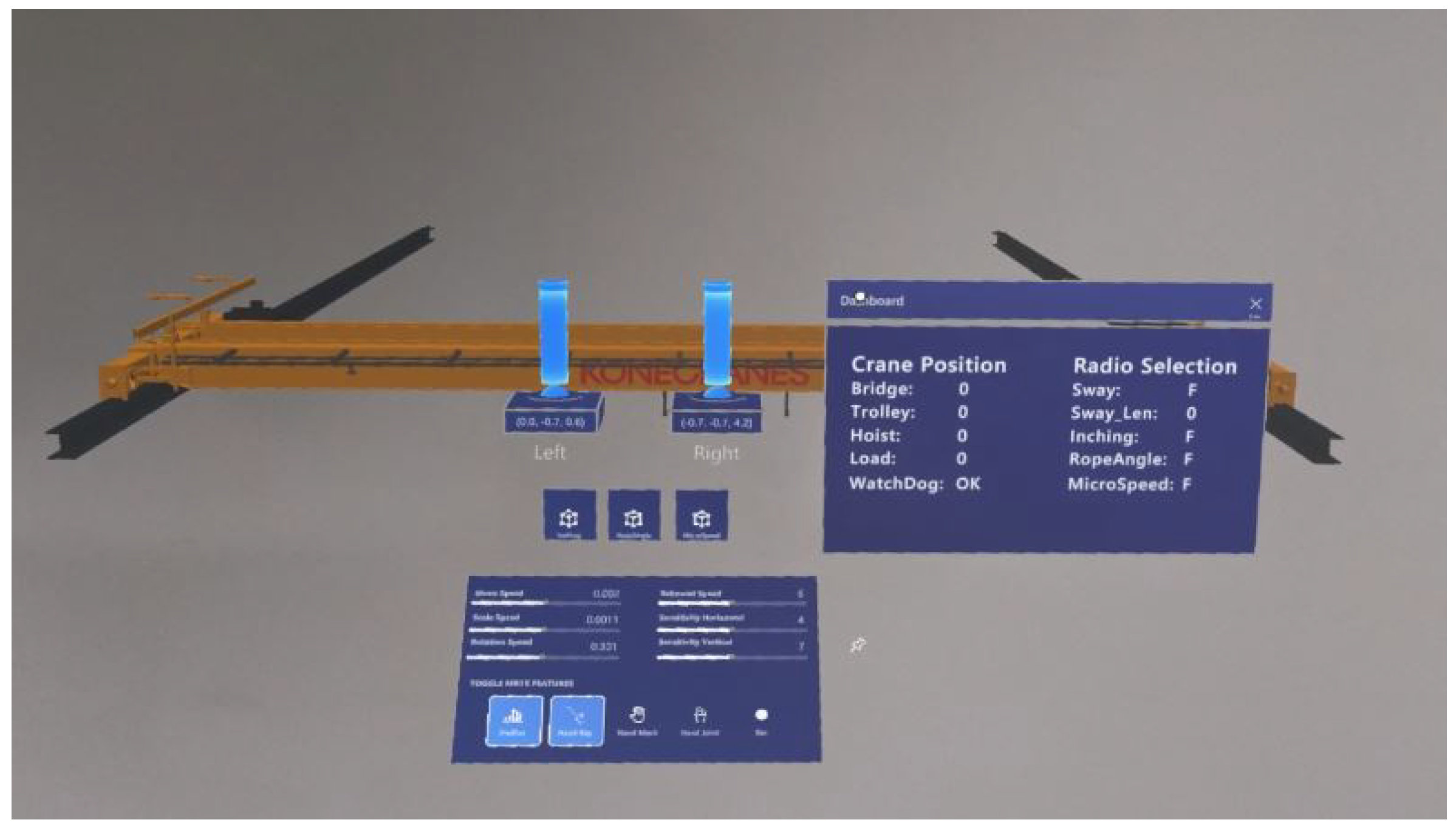
3.2.3. Mixed Reality Control Application

A Microsoft HoloLens 2-based mixed reality application was efficiently developed leveraging the digital assets of the XR environment, shown in Figure 12. To set up the MR environment of HoloLens 2, we leveraged the MRTK to integrate MRTK Extensions and Mixed Reality OpenXR Plugin with Unity. The XR application framework allows developers to concentrate on the frontside UI design instead of the back-end development. The crane model and communication modules can be reused across platforms. In the operational interface, the user can interact with the virtual joysticks and buttons to control the physical crane through the OPC UA-GraphQL wrapper, among which the numerical speed signals converted from the joysticks were transmitted to the physical crane. Furthermore, the dashboard on the right displayed the operational information of the crane. Based on the XR development framework, the cross-platform application can be rapidly deployed to meet the requirements of the different terminal devices.

4. Discussion

Overall, through the aforementioned sections, the integration of XR technology empowers the experience. With the unified data structure and data-flow management, it guarantees collaborative information handling across different layers, networks, and applications. Moreover, coupling with ROS and Unity provides extensive SDKs and APIs to increase development efficiency. Therefore, the XR application framework is characterized by interactivity, interoperability, open-source, and scalability.

4.1. Perception Layer

ROS is open-source software with extensive packages to implement complex control. We developed the crane model in Gazebo, equipped with virtual sensors, to simulate the basic movement of the crane. By integrating the simulation environment into the perception layer, the developers can measure the performance of the developed XR application based on the simulated platform. For most conditions, it is difficult to evaluate the feasibility of the application directly with the physical machine. For example, the Gazebo-based platform provides a complete data transmission process for the responsiveness test. To maximize the performance of the DT model, a dynamic data-driven digital twin model is needed to implement the data exchange between the simulation model and the physical model. Moreover, the kinematic control package was used to simulate the basic movement of the crane in ROS, without advanced features such as anti-sway control. “Ilmatar” crane is equipped with Siemens PLCs to implement the smart features. The external additional software, such as MATLAB, could be imported to realize the advanced control simulation. In the meantime, integration with arm robots and autonomous vehicles driven by ROS in the perception layer will contribute to the collaborative control research work.

4.2. Network Layer

In the network layer, we developed three kinds of communication middleware, OPC UA-MQTT wrapper, OPC UA-GraphQL wrapper, and OPC UA-Unity client. OPC UA allows to freely interact with high-end server applications by the cost-effective dedicated controller, such as the Raspberry Pi. Moreover, OPC UA integrates industry-specific data models from several industry trade organizations. It can transmit data from a simple state to a large amount of highly complex factory-wide information. However, its flexibility is based on complex and verbose specifications. Meanwhile, MQTT is based on the Publish/Subscribe architecture, and data is completely decoupled with the event producer and event consumer. Hence, MQTT is easily understandable and rapidly deployable. GraphQL is a query language providing a complete description of the data in one’s API. We conducted the responsiveness test based on three kinds of communication middleware, and found that the average response time of each communication middleware is less than 0.6 s, which can meet the control requirement of the crane in the laboratory environment. Moreover, the OPC UA-MQTT wrapper has the best performance with an average response time of less than 0.3 s. In our framework, the response time of the OPC UA client in Unity is constrained by the refresh rate of Unity. We set the refresh rate as 1 s for the subscription function to subscribe to the value. That is the reason why the OPC UA-GraphQL and OPC UA Client performed closely. For the OPC UA-GraphQL wrapper and OPC UA Client in Unity, we also can improve the refresh rate of Unity to increase the response time. However, it will account for a larger computing resource. Therefore, to face complex operational scenarios, the balancing point between the response time and rendering effect should be further discussed.

4.3. Service Layer

We used Unity as the physical engine platform in the service layer. The advantages of Unity are obvious: it is free for the non-profit developers and accessible for the potential practitioners; Comprehensive documentation and extensive packages can be easily accessed; it supports the OpenXR standard, as well as provides the specific SDK for the Microsoft HMD, to largely increase the development efficiency; its cross-platform capability guarantees the reusability of the asset among different devices. The crane model and functional scripts developed in Unity can be repeatably used in different applications and built to the targeting terminal devices according to the applied scenarios. Furthermore, the various network APIs of Unity empowers interoperability, realizing the data interaction between the service layer and the network layer.
VR training empowers workers’ skill acquisition in industrial contexts. It is especially important in operations that pose some risk due to repeated actions during the work. For instance, virtual training can benefit the workforce by providing a safe environment without exposing them to potential risks. On the other hand, VR training is cost-efficient for discrete event simulation. Our case enables us to provide an immersive experience integrated with the aforementioned multi-feature, i.e., virtual hand, multimedia, and multi-modal interaction. Meanwhile, the VR design document provides a comprehensive guide for the developers. However, to further improve the immersion and avoid the strangeness of the VR environment, a remote controller shall be designed that is compatible with Unity to substitute the self-contained controllers of the XR HMD (Head-Mounted Device). For the VR device, Oculus and Varjo support different operating systems, Android and Windows, respectively. Based on the cross-platform property of Unity, only the corresponding user interfaces were redesigned for the different controllers, and other assets can be commonly used in two VR headsets. Oculus Quest 2 is a wireless device providing enough mobility for the user; however, it is hard to provide high-resolution rendering and real-time data processing due to its limited computing capability. In the meantime, Varjo XR-1 is a cable-connected device offering excellent rendering and powerful computing ability. Hence, for the high requirements of synchronized data analysis and a more immersive experience, Varjo can be a better choice, while Oculus is suitable for the extensive movable scenarios. For the MR device, HoloLens can free the user’s hands and provide more virtual information superimposed on the physical machine. HoloLens is suitable for the operator to use onsite to complete repeated complicated assembly work or maintenance work.
Additionally, DT empowers the accessibility of the data and information transmitted in the industry via integrated communication chains [66]. Leveraging the XR technology, most of the monitoring data could be visualized in the XR environment, and used for monitoring, supervising, and controlling remotely the production processes. Based on the development framework, we effectively developed cross-platform and multi-function applications, namely, the remote monitor app and the remote control app. The framework also maximized the reusability of the virtual assets. Because the facility of the “Ilmatar” crane is under reconstruction, the feasibility of the apps interacted with the simulated model, and the latency and performance of the applications shall be measured and evaluated with the physical device in the future.

5. Conclusions

In this work, we presented a systematical XR application development framework based on the DT-integrated overhead crane. We started this work by providing an explanation of the four functional layers, including the perceptional layer with the laboratory-based physical crane and ROS-based simulated crane; the machine communication layer with the middleware that addresses the simulated data; the network layer with the standard interface provided to the external client; as well as the service layer with Unity-based XR applications. Among those, we first developed an ROS-based crane model integrating the virtual sensors in the Gazebo. The setup of the simulated platform provided a complete test environment for the performance of the developed XR applications. Later, the network layer enabled a bridge between ROS and OPC UA corresponding to the same structure as the Siemens PLC-OPC UA server. We then developed three communication middleware of the network layer (i.e., OPC UA-MQTT wrapper, OPC UA-GraphQL wrapper, and OPC UA-Unity client) for different scenarios. Subsequently, we set up the measurement for the responsiveness test of the whole framework. The quantitative performance and the possible applied scenarios were illustrated. Furthermore, based on the discussion of the different communication middleware, we developed Unity-based cross-platform industrial XR applications under the provided framework that runs on the various terminal devices. Finally, we elaborately discussed each layer of the development framework and the potential areas that can be further addressed.
In summary, our research empowered the interactivity between humans and machines. Enabled by the combination of digital twin and XR technologies, the XR-based digital services are expected to increase manufacturing efficiency and human satisfaction.

Author Contributions

Conceptualization, C.Y., X.T., J.A. and K.T.; methodology, C.Y., X.T., J.A. and R.A.-L.; software, C.Y., X.T. and J.M.; resources, C.Y., X.T., J.A., R.A.-L., P.S. and K.T.; writing—original draft preparation, C.Y.; writing—review and editing, C.Y., X.T., J.A., R.A.-L., J.M., P.S. and K.T.; visualization, C.Y.; supervision, K.T.; project administration, C.Y, X.T., J.A., P.S. and K.T.; funding acquisition, K.T. All authors have read and agreed to the published version of the manuscript.

Funding

This research was funded by Business Finland under Grant 3508/31/2019 and ITEA 3 Call 5 “MACHINAIDE”.

Institutional Review Board Statement

Not applicable.

Informed Consent Statement

Not applicable.

Data Availability Statement

The measurement data in the “The Performance of the Framework” section is openly available in Zenodo at https://doi.org/10.5281/zenodo.6620934 (created and accessed on 7 June 2022).

Acknowledgments

The authors would like to thank all “MACHINAIDE” consortium members and those who presented or participated in discussions of this work.

Conflicts of Interest

The authors declare no conflict of interest.

Abbreviations

The following abbreviations are used in this manuscript:
AIICAalto Industrial Internet Campus
APIApplication Programming Interface
ARAugmented Reality
CPSCyber–Physical Systems
DDSData Distribution Service
DTDigital Twin
FOVField of View
GraphQLGraph Query Language
HMIHuman–Machine Interaction
IDEIntegrated Development Environment
IIoTIndustrial Internet of Things
IMUInertial Measurement Unit
M2MMachine-to-Machine
MQTTMessage Queuing Telemetry Transport
MRMixed Reality
MRTKMicrosoft Mixed Reality Toolkit
NASANational Aeronautical Space Administration
OPC UAOpen Platform Communication Unified Architecture
OSEMAOpen Sensor Manager
PLCProgrammable Logic Controller
PLMProduct Lifecycle Management
ROSRobot Operating System
RPCRemote Procedure Call
RTOSReal-Time Operating System
SDFSimulation Description Format
SDKSoftware Development Kit
UIUser Interface
URDFUnified Robot Description Format
VRVirtual Reality
XMLExtensible Markup Language
XRExtended Reality
XRTKExtended Reality Toolkit

References

  1. Skobelev, P.; Borovik, S.Y. On the way from Industry 4.0 to Industry 5.0: From digital manufacturing to digital society. Industry 4.0 2017, 2, 307–311. [Google Scholar]
  2. Xu, X.; Lu, Y.; Vogel-Heuser, B.; Wang, L. Industry 4.0 and Industry 5.0—Inception, conception and perception. J. Manuf. Syst. 2021, 61, 530–535. [Google Scholar] [CrossRef]
  3. Nahavandi, S. Industry 5.0—A human-centric solution. Sustainability 2019, 11, 4371. [Google Scholar] [CrossRef] [Green Version]
  4. Maddikunta, P.K.R.; Pham, Q.V.; Prabadevi, B.; Deepa, N.; Dev, K.; Gadekallu, T.R.; Ruby, R.; Liyanage, M. Industry 5.0: A survey on enabling technologies and potential applications. J. Ind. Inf. Integr. 2021, 26, 100257. [Google Scholar] [CrossRef]
  5. Vogel-Heuser, B.; Hess, D. Guest editorial Industry 4.0–prerequisites and visions. IEEE Trans. Autom. Sci. Eng. 2016, 13, 411–413. [Google Scholar] [CrossRef]
  6. PwC. Industry 4.0: Building the Digital Enterprise. 2016 Global Industry 4.0 Survey. Available online: https://www.pwc.com/gx/en/industries/industries-4.0/landing-page/industry-4.0-building-your-digital-enterprise-april-2016.pdf (accessed on 28 March 2022).
  7. Dalenogare, L.S.; Benitez, G.B.; Ayala, N.F.; Frank, A.G. The expected contribution of Industry 4.0 technologies for industrial performance. Int. J. Prod. Econ. 2018, 204, 383–394. [Google Scholar] [CrossRef]
  8. Frank, A.G.; Dalenogare, L.S.; Ayala, N.F. Industry 4.0 technologies: Implementation patterns in manufacturing companies. Int. J. Prod. Econ. 2019, 210, 15–26. [Google Scholar] [CrossRef]
  9. Nayak, N.G.; Dürr, F.; Rothermel, K. Software-defined environment for reconfigurable manufacturing systems. In Proceedings of the 2015 5th International Conference on the Internet of Things (IOT), Seoul, Korea, 26–28 October 2015; pp. 122–129. [Google Scholar]
  10. Longo, F.; Padovano, A.; Umbrello, S. Value-oriented and ethical technology engineering in industry 5.0: A human-centric perspective for the design of the factory of the future. Appl. Sci. 2020, 10, 4182. [Google Scholar] [CrossRef]
  11. Fatima, Z.; Tanveer, M.H.; Zardari, S.; Naz, L.F.; Khadim, H.; Ahmed, N.; Tahir, M. Production Plant and Warehouse Automation with IoT and Industry 5.0. Appl. Sci. 2022, 12, 2053. [Google Scholar] [CrossRef]
  12. Kaasinen, E.; Anttila, A.H.; Heikkilä, P.; Laarni, J.; Koskinen, H.; Väätänen, A. Smooth and Resilient Human–Machine Teamwork as an Industry 5.0 Design Challenge. Sustainability 2022, 14, 2773. [Google Scholar] [CrossRef]
  13. Ma, X.; Tao, F.; Zhang, M.; Wang, T.; Zuo, Y. Digital twin enhanced human-machine interaction in product lifecycle. Procedia CIRP 2019, 83, 789–793. [Google Scholar] [CrossRef]
  14. Wang, T.; Li, J.; Deng, Y.; Wang, C.; Snoussi, H.; Tao, F. Digital twin for human-machine interaction with convolutional neural network. Int. J. Comput. Integr. Manuf. 2021, 34, 888–897. [Google Scholar] [CrossRef]
  15. Cimino, C.; Negri, E.; Fumagalli, L. Review of digital twin applications in manufacturing. Comput. Ind. 2019, 113, 103130. [Google Scholar] [CrossRef]
  16. Boschert, S.; Rosen, R. Digital twin—The simulation aspect. In Mechatronic Futures; Springer: Cham, Switzerland, 2016; pp. 59–74. [Google Scholar]
  17. Grieves, M.; Vickers, J. Digital twin: Mitigating unpredictable, undesirable emergent behavior in complex systems. In Transdisciplinary Perspectives on Complex Systems; Springer: Cham, Switzerland, 2017; pp. 85–113. [Google Scholar]
  18. Glaessgen, E.; Stargel, D. The digital twin paradigm for future NASA and US Air Force vehicles. In Proceedings of the 53rd AIAA/ASME/ASCE/AHS/ASC Structures, Structural Dynamics and Materials Conference 20th AIAA/ASME/AHS Adaptive Structures Conference 14th AIAA, Honolulu, HI, USA, 23–26 April 2012; p. 1818. [Google Scholar]
  19. Reid, J.; Rhodes, D. Digital system models: An investigation of the non-technical challenges and research needs. In Conference on Systems Engineering Research, Systems Engineering Advancement Research Initiative; Massachusetts Institute of Technology: Cambridge, MA, USA, 2016. [Google Scholar]
  20. Fera, M.; Greco, A.; Caterino, M.; Gerbino, S.; Caputo, F.; Macchiaroli, R.; D’Amato, E. Towards digital twin implementation for assessing production line performance and balancing. Sensors 2019, 20, 97. [Google Scholar] [CrossRef] [Green Version]
  21. Wang, W.; Guo, H.; Li, X.; Tang, S.; Li, Y.; Xie, L.; Lv, Z. BIM Information Integration Based VR Modeling in Digital Twins in Industry 5.0. J. Ind. Inf. Integr. 2022, 28, 100351. [Google Scholar] [CrossRef]
  22. Tao, F.; Cheng, J.; Qi, Q.; Meng, Z.; He, Z.; Sui, F. Digital twin-driven product design, manufacturing and service with big data. Int. J. Adv. Manuf. Technol. 2018, 94, 3563–3576. [Google Scholar] [CrossRef]
  23. Schroeder, G.N.; Steinmetz, C.; Pereira, C.E.; Espindola, D.B. Digital twin data modeling with automationml and a communication methodology for data exchange. IFAC-PapersOnLine 2016, 49, 12–17. [Google Scholar] [CrossRef]
  24. Yildiz, E.; Møller, C.; Bilberg, A. Virtual factory: Digital twin based integrated factory simulations. Procedia CIRP 2020, 93, 216–221. [Google Scholar] [CrossRef]
  25. Pérez, L.; Rodríguez-Jiménez, S.; Rodríguez, N.; Usamentiaga, R.; García, D.F. Digital twin and virtual reality based methodology for multi-robot manufacturing cell commissioning. Appl. Sci. 2020, 10, 3633. [Google Scholar] [CrossRef]
  26. Autiosalo, J.; Siegel, J.; Tammi, K. Twinbase: Open-source server software for the Digital Twin Web. IEEE Access 2021, 9, 140779–140798. [Google Scholar] [CrossRef]
  27. Autiosalo, J.; Vepsäläinen, J.; Viitala, R.; Tammi, K. A feature-based framework for structuring industrial digital twins. IEEE Access 2019, 8, 1193–1208. [Google Scholar] [CrossRef]
  28. Dotoli, M.; Fay, A.; Miśkowicz, M.; Seatzu, C. An overview of current technologies and emerging trends in factory automation. Int. J. Prod. Res. 2019, 57, 5047–5067. [Google Scholar] [CrossRef]
  29. Lee, J.; Bagheri, B.; Kao, H.A. A cyber-physical systems architecture for industry 4.0-based manufacturing systems. Manuf. Lett. 2015, 3, 18–23. [Google Scholar] [CrossRef]
  30. Gorecky, D.; Schmitt, M.; Loskyll, M.; Zühlke, D. Human-machine-interaction in the industry 4.0 era. In Proceedings of the 2014 12th IEEE International Conference on Industrial Informatics (INDIN), Porto Alegre, Brazil, 27–30 July 2014; pp. 289–294. [Google Scholar]
  31. Dammann, M.P.; Steger, W.; Stelzer, R. Automated and adaptive geometry preparation for ar/vr-applications. J. Comput. Inf. Sci. Eng. 2022, 22, 031010. [Google Scholar] [CrossRef]
  32. Bellalouna, F. Industrial Case Studies for Digital Transformation of Engineering Processes using the Virtual Reality Technology. Procedia CIRP 2020, 90, 636–641. [Google Scholar] [CrossRef]
  33. Arjun, S.; Murthy, L.; Biswas, P. Interactive Sensor Dashboard for Smart Manufacturing. Procedia Comput. Sci. 2022, 200, 49–61. [Google Scholar] [CrossRef]
  34. Burghardt, A.; Szybicki, D.; Gierlak, P.; Kurc, K.; Pietruś, P.; Cygan, R. Programming of industrial robots using virtual reality and digital twins. Appl. Sci. 2020, 10, 486. [Google Scholar] [CrossRef] [Green Version]
  35. He, F.; Ong, S.K.; Nee, A.Y. An Integrated Mobile Augmented Reality Digital Twin Monitoring System. Computers 2021, 10, 99. [Google Scholar] [CrossRef]
  36. Majewski, M.; Kacalak, W. Human-machine speech-based interfaces with augmented reality and interactive systems for controlling mobile cranes. In International Conference on Interactive Collaborative Robotics; Springer: Cham, Switzerland, 2016; pp. 89–98. [Google Scholar]
  37. Lin, Z.; Petzold, F.; Hsieh, S. 4D-BIM Based Real Time Augmented Reality Navigation System for Tower Crane Operation. In Construction Research Congress 2020: Computer Applications; American Society of Civil Engineers: Reston, VA, USA, 2020; pp. 828–836. [Google Scholar]
  38. Quandt, M.; Beinke, T.; Freitag, M.; Kölsch, C. Requirements for an Augmented Reality-Based Assistance System. In International Conference on Dynamics in Logistics; Springer: Cham, Switzerland, 2018; pp. 335–340. [Google Scholar]
  39. Pooladvand, S.; Taghaddos, H.; Eslami, A.; Nekouvaght Tak, A.; Hermann, U. Evaluating Mobile Crane Lift Operations Using an Interactive Virtual Reality System. J. Constr. Eng. Manag. 2021, 147, 04021154. [Google Scholar] [CrossRef]
  40. Gong, L.; Fast-Berglund, Å.; Johansson, B. A framework for extended reality system development in manufacturing. IEEE Access 2021, 9, 24796–24813. [Google Scholar] [CrossRef]
  41. Catalano, M.; Chiurco, A.; Fusto, C.; Gazzaneo, L.; Longo, F.; Mirabelli, G.; Nicoletti, L.; Solina, V.; Talarico, S. A Digital Twin-Driven and Conceptual Framework for Enabling Extended Reality Applications: A Case Study of a Brake Discs Manufacturer. Procedia Comput. Sci. 2022, 200, 1885–1893. [Google Scholar] [CrossRef]
  42. Pereira, V.; Matos, T.; Rodrigues, R.; Nóbrega, R.; Jacob, J. Extended reality framework for remote collaborative interactions in virtual environments. In Proceedings of the 2019 International Conference on Graphics and Interaction (ICGI), Faro, Portugal, 21–22 November 2019; pp. 17–24. [Google Scholar]
  43. Tu, X.; Autiosalo, J.; Jadid, A.; Tammi, K.; Klinker, G. A Mixed Reality Interface for a Digital Twin Based Crane. Appl. Sci. 2021, 11, 9480. [Google Scholar] [CrossRef]
  44. Yang, C. Framework for Virtual Reality Digital Services Leveraging Digital Twin-Based Crane. Master’s Thesis, Aalto University, Espoo, Finland, 2021. [Google Scholar]
  45. Autiosalo, J. Platform for industrial internet and digital twin focused education, research, and innovation: Ilmatar the overhead crane. In Proceedings of the 2018 IEEE 4th World Forum on Internet of Things (WF-IoT), Singapore, 5–8 February 2018; pp. 241–244. [Google Scholar]
  46. Autiosalo, J.; Ala-Laurinaho, R.; Mattila, J.; Valtonen, M.; Peltoranta, V.; Tammi, K. Towards integrated digital twins for industrial products: Case study on an overhead crane. Appl. Sci. 2021, 11, 683. [Google Scholar] [CrossRef]
  47. Ala-Laurinaho, R.; Autiosalo, J.; Tammi, K. Open Sensor Manager for IIoT. J. Sens. Actuator Netw. 2020, 9, 30. [Google Scholar] [CrossRef]
  48. Luo, W.; Hu, T.; Zhang, C.; Wei, Y. Digital twin for CNC machine tool: Modeling and using strategy. J. Ambient. Intell. Humaniz. Comput. 2019, 10, 1129–1140. [Google Scholar] [CrossRef]
  49. Kostrzewski, M.; Chamier-Gliszczyński, N.; Królikowski, T. Selected reflections on formal modeling in Industry 4.0. Procedia Comput. Sci. 2020, 176, 3293–3300. [Google Scholar] [CrossRef]
  50. Koubâa, A. Robot Operating System (ROS); Springer: Cham, Switzerland, 2017; Volume 1. [Google Scholar]
  51. Wikipedia Contributors. What Is ROS? 2022. Available online: http://wiki.ros.org/ROS/Introduction (accessed on 28 March 2022).
  52. Maruyama, Y.; Kato, S.; Azumi, T. Exploring the performance of ROS2. In Proceedings of the 13th International Conference on Embedded Software, Pittsburgh, PA, USA, 1–10 October 2016; pp. 1–10. [Google Scholar]
  53. Takaya, K.; Asai, T.; Kroumov, V.; Smarandache, F. Simulation environment for mobile robots testing using ROS and Gazebo. In Proceedings of the 2016 20th International Conference on System Theory, Control and Computing (ICSTCC), Sinaia, Romania, 13–15 October 2016; pp. 96–101. [Google Scholar]
  54. OPC FOUNDATION. Unified Architecture. 2022. Available online: https://opcfoundation.org/about/opc-technologies/opc-ua/ (accessed on 28 March 2022).
  55. Leitner, S.H.; Mahnke, W. OPC UA–service-oriented architecture for industrial applications. ABB Corp. Res. Cent. 2006, 48, 22. [Google Scholar]
  56. Mattila, J.; Ala-Laurinaho, R.; Autiosalo, J.; Salminen, P.; Tammi, K. Using Digital Twin Documents to Control a Smart Factory: Simulation Approach with ROS, Gazebo, and Twinbase. Machines 2022, 10, 225. [Google Scholar] [CrossRef]
  57. Chao, Y. OPC-Unity-Client. Available online: https://github.com/talentyc/OPCUA-CLIENT-IN-UNITY (accessed on 12 April 2022).
  58. Soni, D.; Makwana, A. A survey on mqtt: A protocol of internet of things (iot). In Proceedings of the International Conference On Telecommunication, Power Analysis And Computing Techniques (ICTPACT-2017), Chennai, India, 6–8 April 2017; Volume 20, pp. 173–177. [Google Scholar]
  59. Yang, C. OPC UA-MQTT Wrapper. Available online: https://github.com/talentyc/OPCUA-MQTT-GATEWAY-MQTT-UNITY-CLIENT (accessed on 12 April 2022).
  60. Hietala, J. OPC-UA-GraphQL-Wrapper. Available online: https://github.com/AaltoIIC/OPC-UA-GraphQL-Wrapper (accessed on 12 April 2022).
  61. Hietala, J. Real-Time Two-Way Data Transfer with a Digital Twin via Web Interface. Master’s Thesis, Aalto University, Espoo, Finland, 2020. [Google Scholar]
  62. Egliston, B.; Carter, M. Critical questions for Facebook’s virtual reality: Data, power and the metaverse. Internet Policy Rev. 2021, 10, 1–23. [Google Scholar] [CrossRef]
  63. Wikipedia Contributors. OpenXR. 2022. Available online: https://en.wikipedia.org/wiki/OpenXR (accessed on 28 March 2022).
  64. Ala-Laurinaho, R.; Autiosalo, J.; Nikander, A.; Mattila, J.; Tammi, K. Data Link for the Creation of Digital Twins. IEEE Access 2020, 8, 228675–228684. [Google Scholar] [CrossRef]
  65. Ala-Laurinaho, R.; Mattila, J.; Autiosalo, J.; Hietala, J.; Laaki, H.; Tammi, K. Comparison of REST and GraphQL Interfaces for OPC UA. Computers 2022, 11, 65. [Google Scholar] [CrossRef]
  66. Liagkou, V.; Salmas, D.; Stylios, C. Realizing virtual reality learning environment for industry 4.0. Procedia CIRP 2019, 79, 712–717. [Google Scholar] [CrossRef]
Figure 1. Framework and workflow of the applications for a DT-based crane. The whole framework contains four layers: the perception layer with the “Ilmatar” crane and its simulation mode; the machine communication layer assuring the standard data acquisition; the network layer focusing on communication with the external users; and the service layer providing various digital services.
Applsci 12 06030 g001
Figure 2. The description of the overhead crane.
Applsci 12 06030 g002
Figure 3. Workflow of the model conversion from CAD to Unity and Gazebo. It involves two sub workflows, CAD model to Unity and CAD to Gazebo with the corresponding file format.
Applsci 12 06030 g003
Figure 4. The architectures of three kinds of communication middleware: (a) OPC UA-MQTT wrapper. (b) OPC UA-GraphQL wrapper. (c) OPC UA-Unity Client.
Applsci 12 06030 g004
Figure 5. Overview of the service layer. It involved two subsections, namely hardware setup and software development.
Applsci 12 06030 g005
Figure 6. “Ilmatar” crane model in Unity.
Applsci 12 06030 g006
Figure 7. The measurement setup for the responsiveness test.
Applsci 12 06030 g007
Figure 8. The process for the responsiveness test leveraging different communication middleware: (a) Responsiveness test for the OPC UA-GraphQL wrapper. (b) Responsiveness test for the OPC UA-MQTT wrapper. (c) Responsiveness test for the OPC UA Client in Unity.
Applsci 12 06030 g008
Figure 9. VR training app: (a) Be familiar with the fundamental features of the VR environment. (b) Interact with the large-scale remote controller to learn the smart features of the crane via the video stream. (c) Learn how to interact with the gradable same-scale remote controller. (d) Complete the realistic-looking training task.
Applsci 12 06030 g009
Figure 10. The screenshot of the remote monitor prototyping app. The dashboard is located in the upper left corner with operating data. Moreover, mouse control and screen touch can implement the view change.
Applsci 12 06030 g010
Figure 11. The screenshot of the remote control prototyping app. The 2D remote controller is located in the lower and right corner.
Applsci 12 06030 g011
Figure 12. The screenshot of the MR application in HoloLens 2.
Applsci 12 06030 g012
Table 1. Hardware of the crane: subsystems and their basic functional properties.
SubcomponentFeatureValue
HoistLifting height3.0 m
Lifting speed8.0 m/min stepless
TrolleyMovement range9.0 m
Movement speed20.0 m/min stepless
BridgeMovement range19.8 m
Movement speed32.0 m/min stepless
Table 2. XR devices comparison: the basic design parameters and features of three XR devices used in the service layer, namely Oculus Quest 2, HoloLens 2, and Varjo XR-1.
ContentOculus Quest 2HoloLens 2Varjo XR-1
ManufacturerFacebookMicrosoftVarjo Technology
Resolution1832 × 19202 K1920 × 1080
1440 × 1600
Field of View120 ° 43 ° × 29 ° 87 °
Refresh Rate90 Hz60 Hz90 Hz
Tracking Modeinside-outinside-outoutside-in
Hand Tracking
Controller
Virtual Reality
Mixed Reality
Table 3. Definition of data in the XR environment: The research defined the data class, name, basic format, reference type, source, and description to keep consistency with the internal and external interface. The Format defined the data basic type, such as int, float, char, etc. The reference type was categorized as constant and variable. The data source represented the source of the data. The Description depicted the definition of the data.
ClassNameFormatRef_TypeData SourceDescription
DesignHoist_height_maxfloatconstantUnityHoist maximum height
Hoist_height_minfloatconstantUnityHoist minimum height
Hoist_speed_maxfloatconstantUnityHoist maximum speed
Hoist_capacityfloatconstantUnityHoist maximum capacity
Trolley_range_maxfloatconstantUnityTrolley maximum range
Trolley_range_minfloatconstantUnityTrolley minimum range
Trolley_speed_maxfloatconstantUnityTrolley maximum speed
Bridge_range_maxfloatconstantUnityBridge maximum location
Bridge_range_minfloatconstantUnityBridge minimum range
Bridge_speed_maxfloatconstantUnityBridge maximum speed
Coefficient_microspeedfloatconstantUnityMicrospeed scale factor
Coefficient_inching_speedfloatconstantUnityPredefined speed for inching
Coefficient_inching_distancefloatconstantUnityPredefined distance for inching
StatusHoistPositionfloatvariableMiddlewareThe height of the hook block
TrolleyPositionfloatvariableMiddlewareThe location of the trolley
BridgePositionfloatvariableMiddlewareThe location of the bridge
ControlInchingBooleanvariableUnity/MiddlewareInching button status
MicroSpeedBooleanvariableUnity/MiddlewareMicrospeed button status
SwayControlBooleanvariableUnity/MiddlewareSwaycontrol button status
RopeAngleFeatureBypassBooleanvariableUnity/MiddlewareRope angle button status
SwayControl_SlingLength_mmintvariableUnity/MiddlewareThe sling length
Hoist.UpBooleanvariableUnityWhether hoist moves up
Hoist.DownBooleanvariableUnityWhether hoist moves down
Hoist.SpeedfloatvariableUnityThe speed of the hoist
Trolley.ForwardBooleanvariableUnityWhether trolley moves forward
Trolley.BackwardBooleanvariableUnityWhether trolley moves backward
Trolley.SpeedfloatvariableUnityThe speed of trolley
Bridge.ForwardBooleanvariableUnityWhether bridge moves forward
Bridge.BackwardBooleanvariableUnityWhether bridge moves backward
Bridge.SpeedfloatvariableUnityThe speed of bridge
Table 4. The response times in seconds for the different communication middleware. SD = standard deviation.
MinMaxMeanMedianSD
OPC UA-GraphQL wrapper0.011.0230.5050.5080.289
OPC UA-MQTT wrapper0.0040.5450.2730.2830.149
OPC UA Client in Unity0.0011.0010.5310.5520.278
Table 5. Communication middleware comparison: coding language is the programming language needed for the development of the application in the service layer; communication protocol is applied between the network and service layer; learning cost concentrates on the service layer.
Network LayerOPC UA-MQTT WrapperOPC UA-GraphQL WrapperOPC UA-Unity Client
Coding LanguagePython and C#C#C#
Communication ProtocolMQTTHTTPOPC UA
Learning CostMediumLowHigh
Response time0.273 s0.505 s0.531 s
Applied ScenarioContinuous data flow remote monitorDiscrete data request/response interactionComplex information model interaction
Table 6. VR training application design document: The functional features and the interaction features were developed following the design document.
App InfoTitle:
“Ilmatar” crane VR training application
Device:
Oculus Quest 2, Varjo XR-1
BasicsThe user will be able to grab:There will be sockets:
Normal size remote controllerCrane hook block
Joysticks
Normal size remote controller
Events & InteractionsBy default, the left hand will have a:and right hand will have a:
Direct InteractorDirect & Ray Interactor
Left hand can:And right hand can:
Implement continuous move
Grab the normal size remote controller
Interact with joysticks
Interact with the switch button
Implement continuous turn
Grab the normal size remote controller
Interact with joysticks
Interact with the switch button
Interact with UI
If the user is:
Getting close to UI with the right virtual hand, the rayline will occur automatically
Pressing the left trigger button when raycasts show up, UI function will be activated
Pressing the left joystick down, the teleport will be activated
Pressing the grip button, the virtual object can be grabbed
Pressing the trigger button, the grabbing object can be released
Pressing left button B when the hook gets close to the drum, the drum will be hoisted
Pressing left button B when the hook hoists the drum, the drum will be released
Interacting with the switch button by the virtual hand, the button will be rotated
The main menu will be located:
In the front of the virtual environment
There will be additional UI elements for:
Scene 1: Introduction of the VR environment
Scene 2: Getting familiar with the interactive features in the VR environment
Scene 3: Learning about the functional features of the “Ilmatar” crane
Scene 4: Completing a virtual training
Dashboard to show the info of the crane
Functional FeaturesFetch information from the DT document
Support Oculus Quest 2 and Varjo XR-1
Simulate the smart features, snag prevention, micro speed and inching
Other FeaturesRealistic looking virtual hand models will be developed
Interact the controller with the real fingers, the corresponding virtual finger bend
Video stream tutorials about the features of the crane
Sound play while the crane moves
Sound play while interacting with UI
Sound play while releasing anything
Two remote controllers, a large one for the scene 2, the normal one for the scene 4
Publisher’s Note: MDPI stays neutral with regard to jurisdictional claims in published maps and institutional affiliations.

