1. Introduction
CFRP (carbon fiber-reinforced polymers) are widely used in the manufacturing of some complex large aircraft components such as the wing, frame, beam and other structural parts because of its superior mechanical properties such as high strength, light weight, corrosion resistance, strong design ability and good fatigue resistance [
1]. These structural parts need a large number of connecting holes for assembly or connection, and the quality of connecting holes will directly affect the bearing capacity and service life of the aerospace equipment; thus, the aerospace industry has high quality requirements for aircraft connecting holes [
2]. Due to the physical characteristics of heterogeneous and anisotropic CFRP, as well as the characteristics of small fracture strain and low interlaminar bonding strength, fiber pulling, matrix tearing, delamination, burr and other defects often occur during the machining of holes [
3,
4], which seriously affect the accuracy and service life of the products [
5] and sometimes even increase the secondary processing of the deburring process, greatly reducing processing efficiency and making the processing quality costly and difficult to control. Additive manufacturing is a powerful tool for the aerospace industry. Therefore, how to create an efficient, high-quality and low-cost hole machining of composite materials is one of the hot spots and difficulties in research at home and abroad.
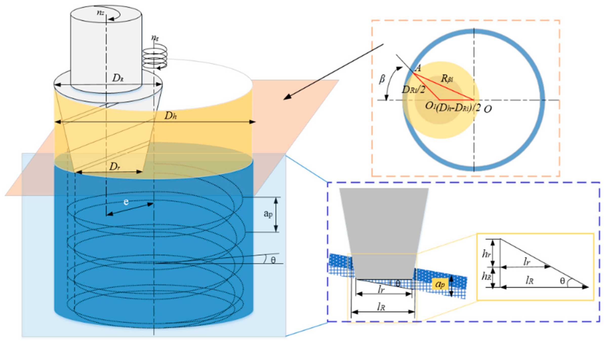
Helical milling is also known as orbital drilling or spiral milling; its working principle is to set the eccentric position of the tool and to integrate the composite spiral cutting technology of the axial feed and circumferential feed movement to complete the machining of the hole parts larger than the tool diameter. This way of eccentric processing improves the heat dissipation of the cutting tool and chip removal condition, and it can significantly reduce the process of the axial cutting force [
6]. The tool periodically mobilizes and speeds up the hole wall and air heat exchanger, effectively reducing the occurrence of mechanical and thermal damage [
7,
8] and improving the processing quality of the hole. This leads to inhibition of the layered composite materials, which prolongs the service life of the cutting tools, and which is suitable for a variety of apertures. It also has other advantages and is widely used in CFRP hole technology.
Domestic and foreign researchers mainly focus on the cutting mechanism, cutting force modeling and hole quality control. Among them, B. Denkena [
9] and Brinksmeier E. et al. [
10] showed, through kinematic analysis of the spiral milling holes, that the end cutting edge and the peripheral edge of the milling cutter participate in the cutting of workpiece materials at the same time. In addition, the peripheral edge of the milling cutter cuts intermittently, and the processing form is similar to that of the peripheral milling. The end cutting edge cuts continuously, and the processing form and insert milling are similar. At the same time, the calculation of the undeformed cutting parameters and material removal volume ratio of the milling cutter edge and the end cutting edge shows that, when the machining aperture and tool diameter are determined, the ratio of material volume of the peripheral edge and end cutting edge is constant and is not affected by the machining parameters [
11]. Traditional spiral milling holes often adopt the cylindrical milling cutter, material removal is mostly conducted by the bottom edge, a weak blade is the main part that completes the processing of the hole wall [
12,
13], and the material removal in the process of the cutting tool’s weak blade is the focus. It is difficult to guarantee the product quality requirements, as the bottom edge material removal volume is larger, and the axial force is big, which is greater than the critical force of delamination, leading to delamination defects in the hole [
14]. Therefore, the finishing processes such as reaming or deburring are required. Based on this, Wei [
15] and Chen et al. [
16] successively proposed the processing strategy of two-way spiral milling. In the process of reverse cutting, the material itself was used as support to enhance the constraint rigidity, and a two-way milling cutter was designed to enrich the experimental study of the reverse spiral hole and to verify the feasibility of the cutting process of a bidirectional progressive spiral milling hole.
At the same time, based on the basic principle of spiral hole milling, some researchers introduced an ultrasonic generator to output ultrasonic oscillation, and found that the effective cutting time of the tool in vibration cutting is shorter than that of ordinary cutting time [
15], and the periodic separation of the tool and the workpiece leads to the periodic change of cutting speed and cutting depth [
17]. Regarding changing the cutting mechanism in the cutting process, ultrasonic machining compared with the traditional machining method has a huge advantage. Takeyama [
18] and Makhdum [
19] successively conducted ultrasound-assisted carbon fiber drilling, and they found that the cutting force was significantly reduced and the quality of the parts was greatly improved. Zhang Liaoyuan [
20], Hu Erjuan [
21], and Zhang et al. [
22] established the theoretical model of cutting force of ultrasonic vibration cutting CFRP and compared it with the experimental results, and they found that the theoretical prediction and the measured results are in good agreement. Under the same cutting parameters, the average axial force can be reduced by 20–30% [
20], and the cutting stress is more concentrated, which is beneficial to the shear fracture of the fiber [
21] and improves the machining efficiency [
22]. Zhang Deyuan [
23] further proposed a new process method of ultrasonic vibration sheath–reaming–shaving, and researched and realized high-quality, efficient, and low-cost processing to meet the requirements of precision assembly manufacturing.
From what has been discussed above, spiral milling technology still cannot solve the machining defects of carbon fiber holes such as burr and delamination. There are still technical problems to be solved in the process of carbon fiber holes, such as a high-quality removal mechanism and a high-performance cutting tool design. Therefore, this paper puts forward four stages of a bidirectional progressive spiral milling material removal method to further study the mechanism of ultrasonic milling and the self-designed bidirectional progressive milling cutter, which were used to verify the mechanism of material removal and state of axial force. This study can effectively fill the gap of high-quality processing technology of carbon fiber composites, can solve the technical problems caused by excessive axial force in the process of aerospace carbon fiber processing, and can enrich the technical field of carbon fiber composite processing tool design.
3. Analysis of the Cutting Principle of Ultrasonic-Assisted Progressive Milling
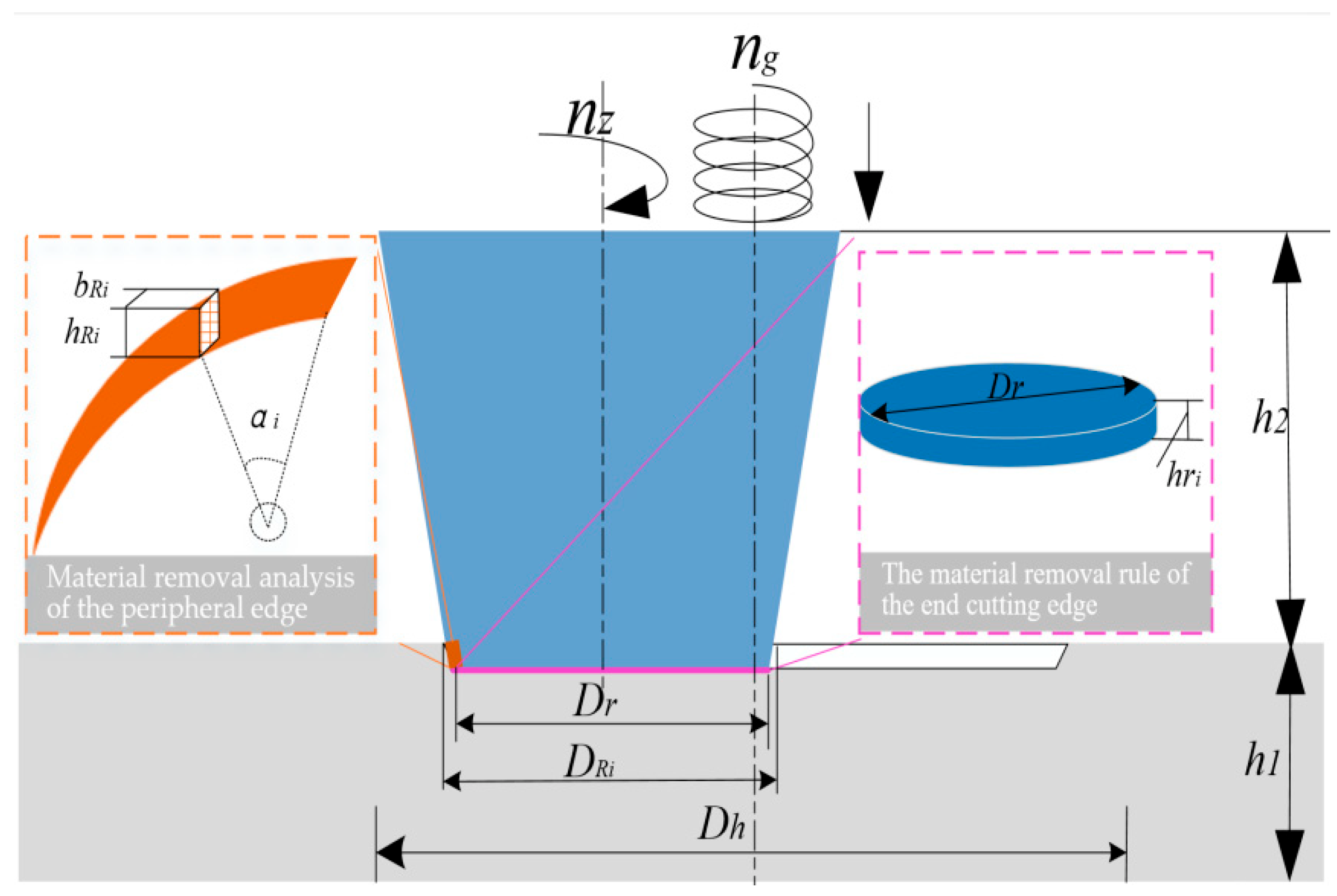
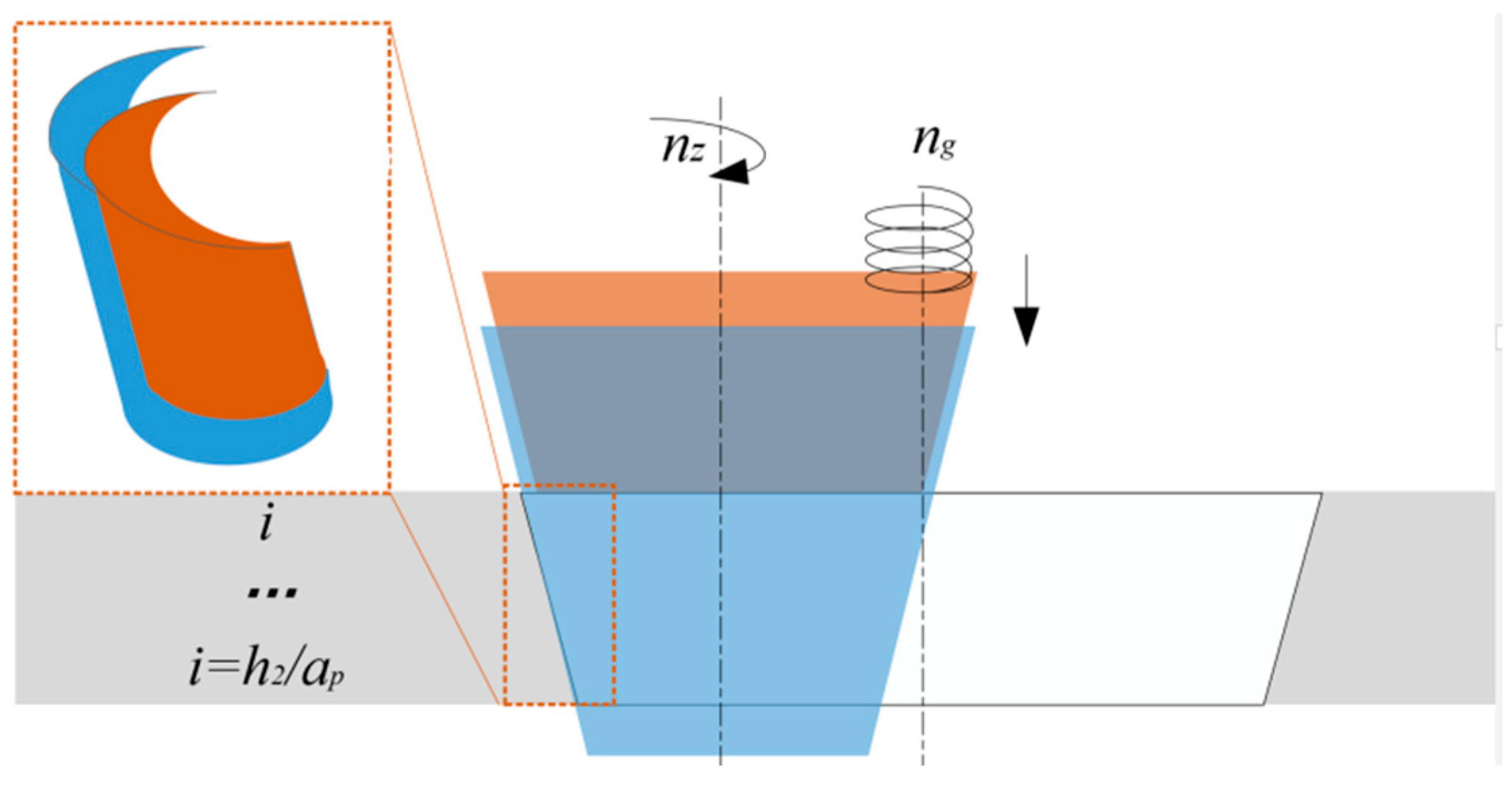
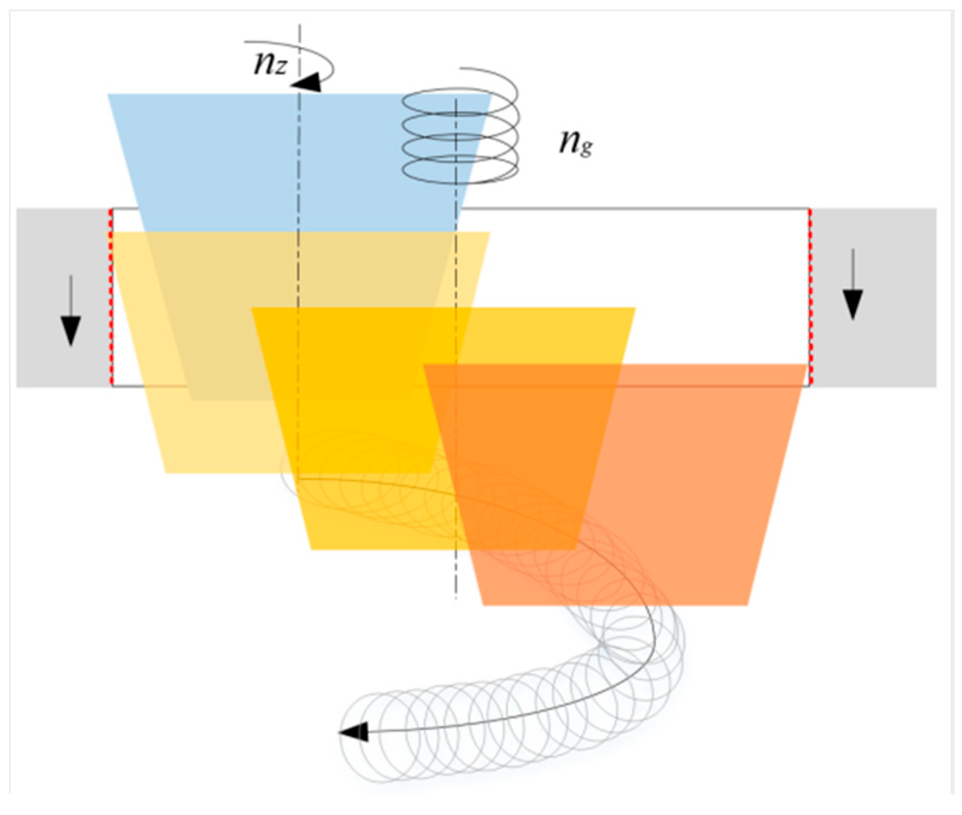
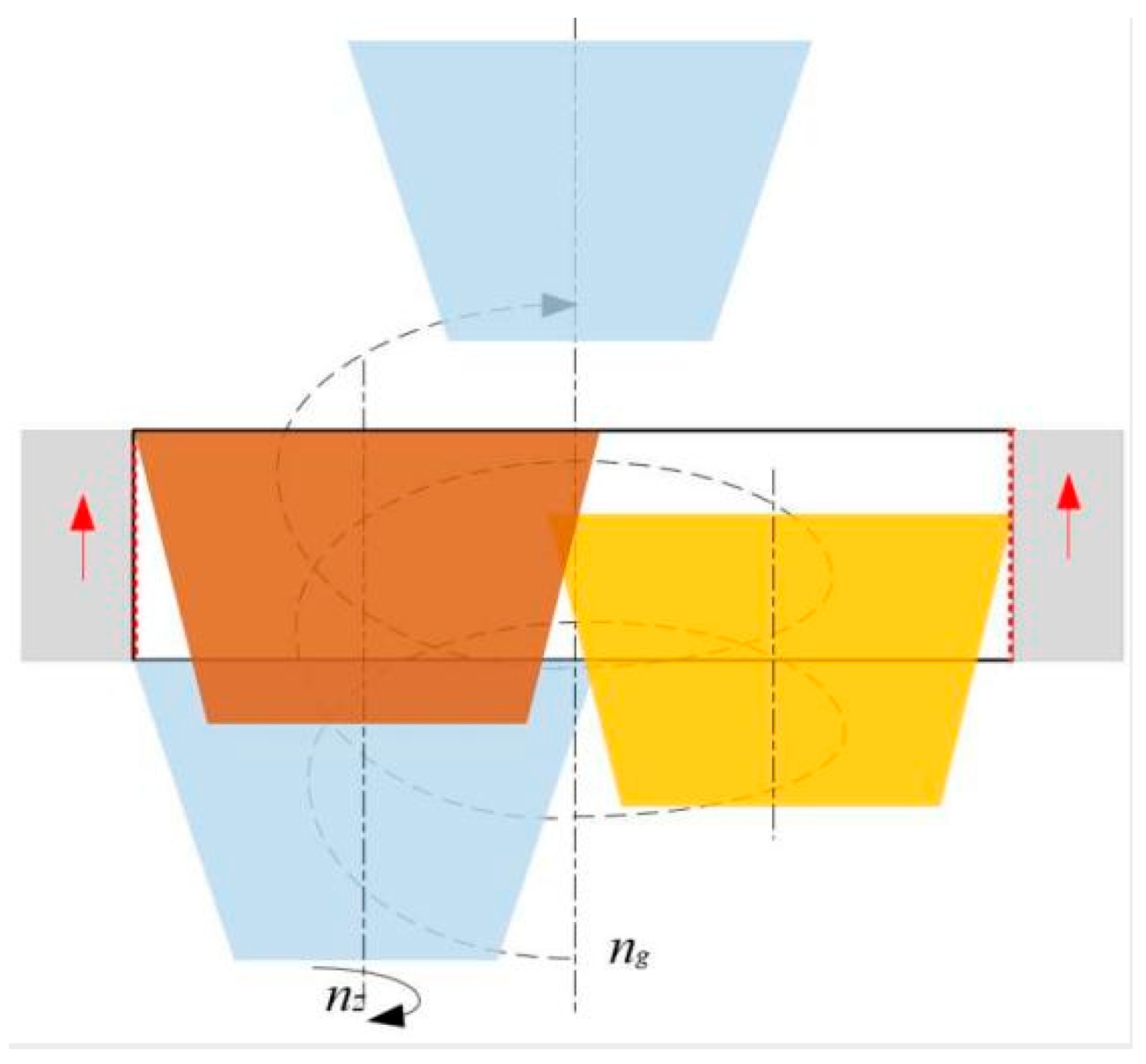
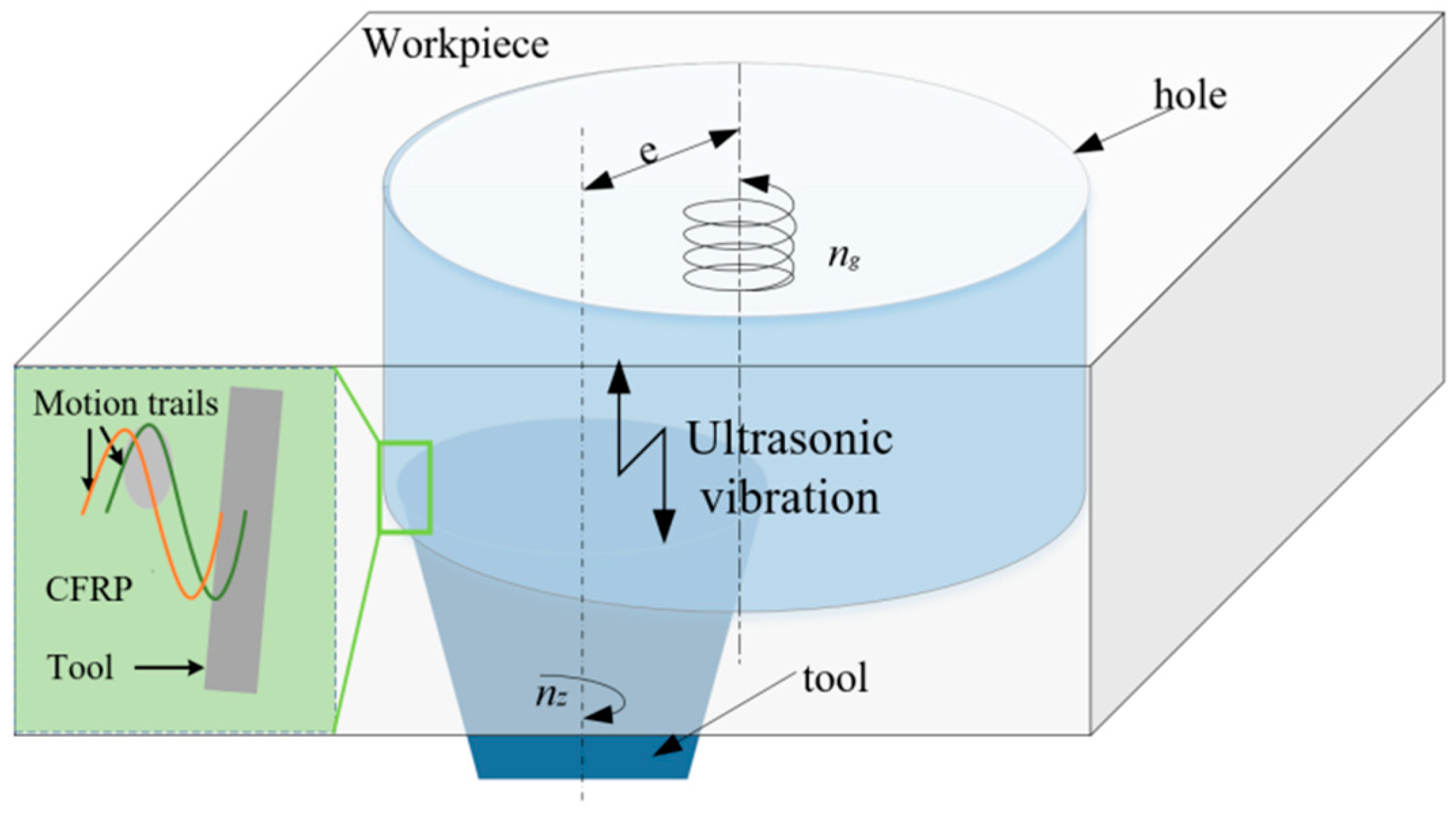
Ultrasonic-assisted conical spiral milling is a machining strategy that uses a conical milling cutter for bidirectional spiral milling CFRP. Ultrasonic-assisted machining changes the motion trajectory of the cutting edge, specifically involving the end cutting edge, the periphery edge, and the reverse cutting edge, which causes a periodic pulse effect on the tool motion trajectory in different cutting stages and improves the machining quality of the hole wall.
(1) As shown in
Figure 6, the end cutting edge begins to participate in the cutting during stage I, which is equivalent to a hammer with high frequency vibration, and which is assumed to have numerous micro-element cutting edges. The trajectory length is lw in an ultrasonic vibration cycle, and we can obtain [
19]:
where
r is the radius of any cutting position of a milling cutter;
z is the amplitude of the ultrasonic vibration;
f is the frequency of the ultrasonic vibration.
In one ultrasonic vibration cycle, material removal volume
Vc of the end cutting edge cutting element in the ultrasonic milling process can be expressed as:
where
Sw is the cross sectional area of the cutting edge element.
If the number of elements involved in the cutting at the end cutting edge of the tool is
N, then according to the material removal, the amount is:
where
is the density of the carbon fiber composites (g/cm
3);
Mw is the total amount of removal during a period vibration by ultrasonic milling.
It can be seen from the equation that, on the premise of the same nominal diameter, the diameter of the bottom edge of the traditional cylindrical milling cutter is different from that of the conical milling cutter, and the relationship is as follows:
where
is the diameter of the top edge of the peripheral edge, the nominal diameter;
is the diameter of the top edge of the end of the cutting edge (mm);
is the cone angle (°);
is the axial length of the peripheral edge (mm);
is the nominal diameter of the cylindrical milling cutter (mm);
is the diameter of the bottom edge of the cylindrical milling cutter (mm).
It can be seen that compared with a traditional cylindrical milling cutter, the amount of material out of an ultrasonic spiral milling cutter is smaller in the cutting stage of the bottom edge, which will significantly affect the chip deformation and create a small change. It has a positive effect on the reduction of axial force.
The fracture of the carbon fiber composite element is mainly a shear fracture. According to Reference [
19], the shear force Fτ of the cutting edge cutting fiber bundle can be expressed as:
where
E is the axial modulus of elasticity (GPa);
Nc is the number of broken fibers;
b is the radius of the fiber element (um);
H is the cutting edge length of fiber bundle cut (um);
v is the Poisson’s coefficient.
Therefore, different cutting lengths of the fiber bundle require different shear forces. For cylindrical and conical milling cutters with the same nominal diameters, the bottom edge relationship is as follows:
The length of the cutting fiber bundle is different, and the shear force required by the tapered milling cutter is less than that of the cylindrical milling cutter in the cutting stage of the bottom edge. Therefore, the bottom edge of the tapered milling cutter reduces the cutting axial force to a great extent. At the same time, due to the small amount of material removal, the reserved material allowance can be used as support to enhance the material rigidity of the subsequent milling hole.
(2) As the peripheral edge enters the cutting stage, the fiber rebounds and minimal material allowance removal requirements may occur, as most of the allowance has been removed in the first and second stages. After the introduction of ultrasonic-assisted processing, the movement direction of the cutting edge without an ultrasonic trajectory is an angle between the direction of the delta in a vibration cycle, which changes over time; thus, the impact of the cutting edge effect on the material changes direction. The theoretical trajectory is shown, and the ultrasonic vibration caused by the impact of the
Fm, is as follows:
where
is the quality of the cutting edge elements;
t is the time.
After the ultrasonic vibration is applied in the vertical direction of the fiber axis, the resultant force
of the tangential force and radial force of the cutting edge can be expressed as:
where
is the tangential force (N);
is the radial force (N);
is the angle between the cutting edge movement direction and carbon fiber parts.
Then, the fiber bundle at the aperture begins to fracture, and the force applied meets the relationship:
It can be seen that the ultrasonic vibration processing accumulates the ultrasonic impact effect in the cutting process, which makes it easier to cut the carbon fiber and to fracture the material, thus improving the processing efficiency. As shown in
Figure 6, in this stage, until the top of the edge gradually exits the hole wall milling and when the exit may face the burr removal processing requirements, considering the cumulative effect of the ultrasonic vibration, the cutting edge will increase in impact force, making it easier to cut the carbon fiber, thus improving the surface quality and processing efficiency.
(3) In the final hole finishing stage of the reverse cutting edge, the material removal is small. With the aid of ultrasonic vibration, the tool movement relative to the workpiece is not unidirectional in the axial upward direction, but the cyclic reciprocating movement is. Therefore, after the machined surface formation, and through the reverse cutting edges along the axis of forward, backward and forward for the repeat ironing effect, the essence of the ultrasonic vibration cutting process under the reverse action consists of the combination of cutting and ironing, which can significantly improve the quality of the processing surface. It is also suitable for reverse cutting with a certain allowance. This process is shown in
Figure 7: the dotted line is the route of the ironing, and the solid line is the cutting direction of the feed path identification.
In conclusion, the ultrasonic movement of the reverse cutting edge can enhance the effect of extrusion and ironing; thus, the reverse cutting process is a combined action process of cutting, extrusion and grinding.
4. Experimental Analysis
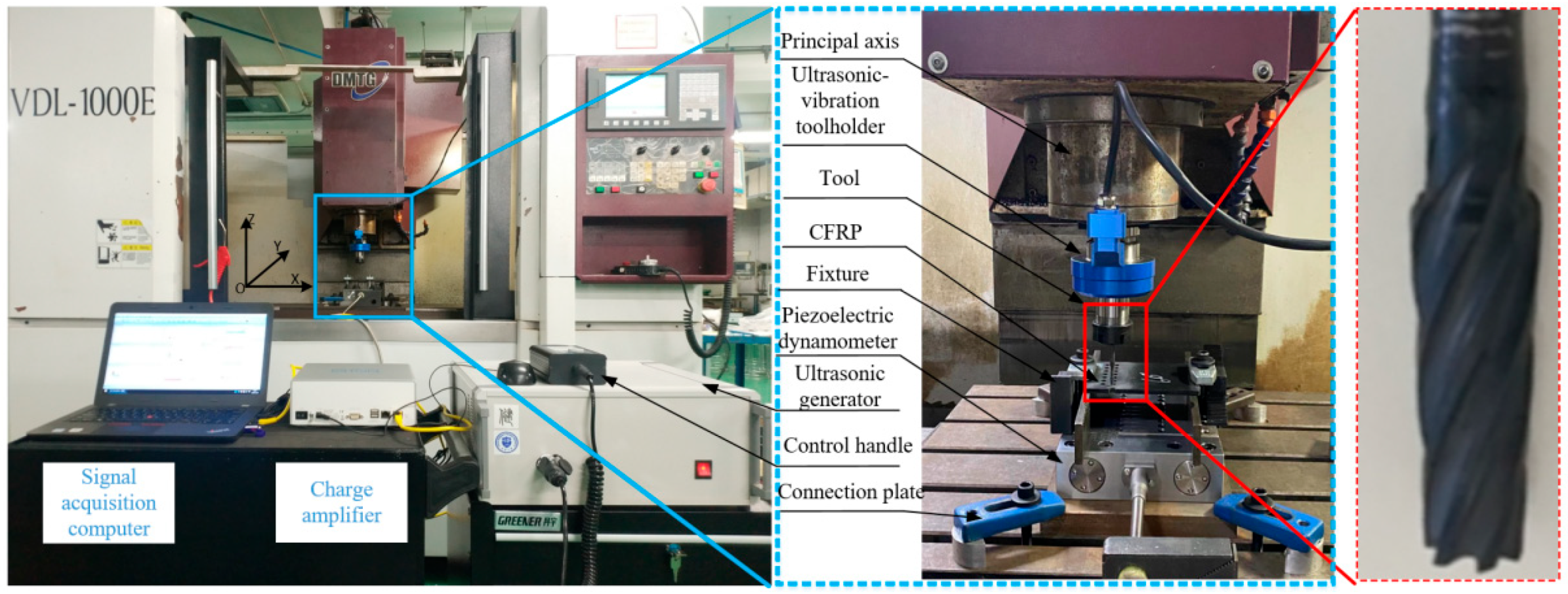
In this paper, experimental research was carried out to explore the cutting mechanism and the influence of ultrasonic vibration on the cutting force of the ultrasonic-assisted bidirectional cone spiral incremental milling hole. The VDL-1000E high speed milling NC machining center produced by Dalian Machine Tool Plant was used in the test. The spindle speed range was 45–8000 rpm, and the feed speed range was 1–10,000 r/min
−1. The ultrasonic vibration equipment used in the test was USBT40ER32, an inductive rotary ultrasonic vibration processing tool handle independently developed by Tianjin University. The piezoelectric force sensor Kistler 9139AA three-way dynamometer was used to collect and record the milling force.
Figure 8 shows the test site. After the hole-making process was completed, a dust mask is worn and a vacuum cleaner is used to vacuum the powder-like chips generated during the cutting process.
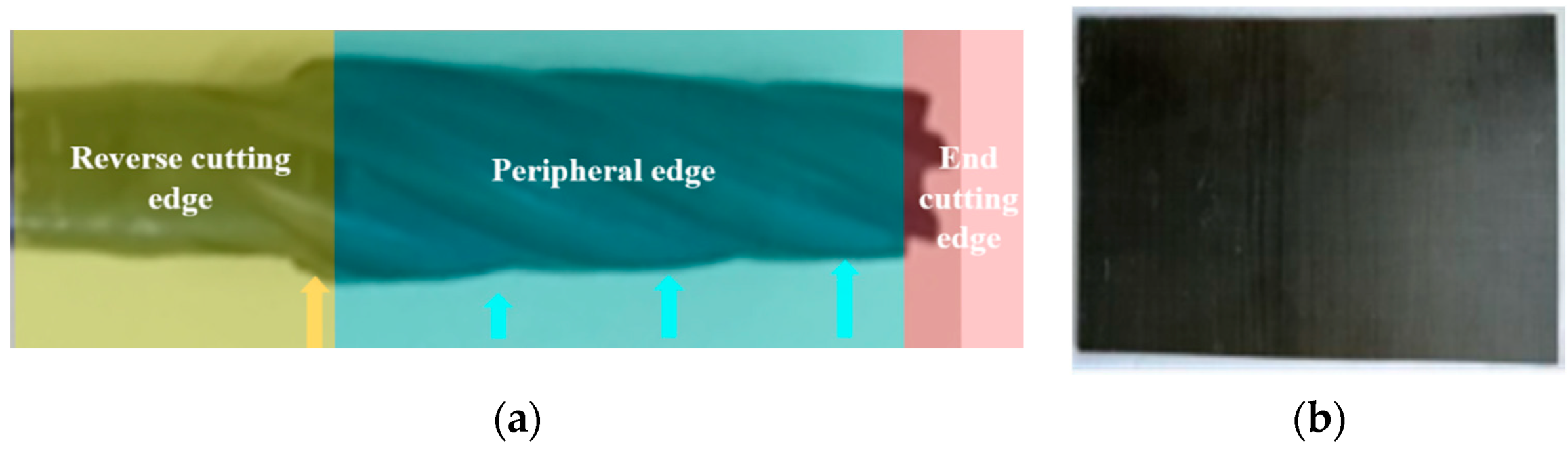
In this test, a bi-directional conical ultrasonic milling cutter was selected, and a reverse milling structure was added, as shown in
Figure 9a. That is, a reverse cutting edge with gradual deformation was added at the top of the milling cutter edge for reverse finishing of the hole wall of the carbon fiber composite materials. The tool base material is a YG8-type hard alloy with a diamond coating. The diameter of the bottom edge is 4 mm, the maximum diameter of the top diameter of the peripheral edge is 6 mm, the axial length of the edge is 10 mm, the number of teeth is 6, the rake is 6°, the relief angle is 12°, the spiral angle is 30°, and the taper is 11.4°.
- 2.
Experimental material
In this test, a one-way CFRP sheet was used for ultrasonic vibration spiral milling. The type of carbon fiber composite was T700, and the matrix material was epoxy resin. The selected sheet sizes were 200 mm in length, and 110 mm in width and in height. The cutting parameters are as follows in
Table 1.
- 3.
Analysis of cutting force
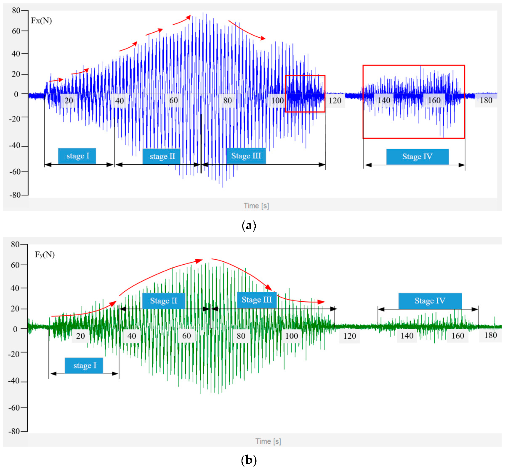
The cutting force curve can be obtained through the test. As shown in
Figure 10,
Fx and
Fy gradually increase as the cutting tool enters the cutting state and as it enter the first stage of stable cutting, at which the bottom edge and the peripheral edge participate in cutting. The cutting length of the peripheral edge gradually increases, and the cutting force gradually reaches the peak. The bottom edge is then out of the cutting process, cutting into the second stage. At this time, only the edge participates in the cutting, with the edge axial downward feed, the cutting volume gradually reduced, and the cutting force also monotonically changing with a decreasing trend. When the top of the peripheral edge exits the cutting process, the cutting force drops to the lowest point, which is the third stage. At this time, the cutting force is not zero, because there is a pressure foot in the experimental system. In the process of reverse cutting, the material removal is small, which verifies that during the above mechanism analysis, there may be an elastic rebound, burr and other processing allowance, under the action of reverse cutting edge extrusion, ultrasonic ironing, and the finishing machining.
In
Figure 11, it is clearly reflected that the changing state of
Fz at the beginning of the cutting, the cutting force mutation with the bottom edge, and the edge begin to participate in the cutting, ultrasonic-assisted vibration generated by the impact force, which makes the cutting force fall to stable, where the cutting becomes light and enters into stable cutting, stage I. As the bottom edge exits the milling process, it can be seen from the curvature of the falling axial force that the cutting removal amount is small and falls in a uniform decreasing way. The reason is that the peripheral edge gradually cuts uniformly downward, the cutting removal is gradually reduced, and at the same time, the top cutting edge involved in the cutting removal is small, which indicates stage II. As the top cutting edge of the peripheral edge exits and the third stage begins, the cutting force is reduced to a minimum.
In the fourth stage of reverse cutting, the main fiber fracture mode is changed from extrusion to cutting and rolling, the material removal and deformation are low, and the axial force is lower than the critical value of the interlayer binding force; however, there are some jump points in the figure, which are caused by fiber rebound or burr in the hole wall position and by the cutting force mutation.
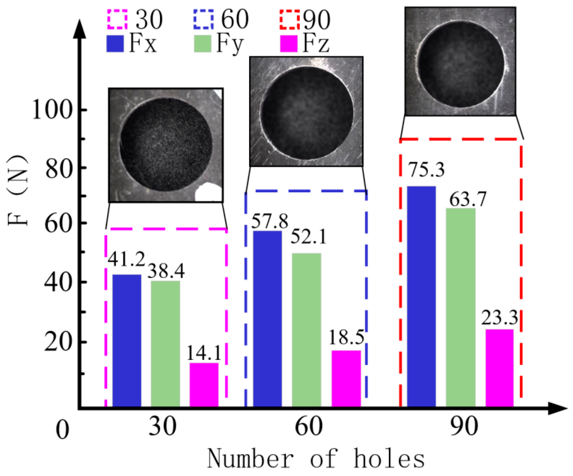
According to the analysis in
Figure 12, it can be seen that with the increase in the number of hole makings, Fx and Fy increased by 30.27% and 22.26%, respectively, with the increase in the number of processed holes at 90, which leads to an increase in tool wear, and which makes it difficult for the tool to remove the material, leading to a gradual increase in cutting force [
24]. However, in the aspect of axial force, under the ultrasonic vibration impact, the cutting becomes easy and fast, and the axial force is still at a relatively low level. After 60 holes were processed, the axial force was about 18.5 N, which was reduced by 48% compared with the reference; after 90 holes were machined, the axial force was only 23.3 N, almost equal to the axial force level recorded in the reference in the initial machining state [
25], which effectively avoids the tearing of carbon fiber materials, and no obvious delamination defects occurred in the holes.


