Article

Study on the Bending Stiffness of Joints Connecting Porcelain Bushings and Flanges in Ultra-High Voltage Electrical Equipment

1
Global Energy Interconnect Research Institute, Beijing 102211, China
2
School of Transportation Science and Engineering, Beihang University, Beijing 100191, China
*
Author to whom correspondence should be addressed.
Appl. Sci. 2022, 12(12), 5899; https://doi.org/10.3390/app12125899
Submission received: 20 April 2022 / Revised: 29 May 2022 / Accepted: 8 June 2022 / Published: 9 June 2022

Abstract

:
In this study, the equivalent bending stiffness of cement-bonded joints connecting the porcelain bushing and flange in ultra-high voltage (UHV) electrical equipment was investigated. A mechanical bending model of the joint was developed based on its structural features, and a new equation for the equivalent bending stiffness of the joint was proposed. Based on experimental data for nine UHV porcelain bushings, a dimensionless elasticity coefficient for the equivalent bending stiffness equation was determined. Finally, considering two 1000 kV arresters as examples, the bending stiffness was calculated using the equation proposed in this paper and that which is used in China’s seismic code. A comparison of the results shows that the equation proposed in this study is in better agreement with the experimental data. Compared with the code equation, the equation in this paper adopts the expression for the dimensionless coefficient, which can more reasonably reveal the bending mechanism of the joint.

1. Introduction

Porcelain electrical equipment is an important part of power systems and plays an essential role in their stability and security. Earthquake disaster investigations have shown that porcelain electrical equipment is easily damaged, making it the part of the power system with the weakest seismic resistance [1,2,3,4]. There is a large volume of published studies assessing the susceptibility of porcelain electrical equipment but without a deeper investigation of its mechanical mechanisms [5,6,7,8].
In porcelain electrical equipment, a joint is formed at the connection of the flange and porcelain bushing. This joint is the point that is the most vulnerable to earthquake damage [9,10,11]. The joint is made of two different materials: a cup-shaped iron flange and a cylindrical porcelain bushing, which are bonded by cement or clamped with a spring. Owing to the complexity of the joint structure, it is difficult to determine the bending stiffness accurately, which is an important constitutive parameter of the joint. Therefore, determining the bending stiffness of the joint connecting the porcelain bushing and flange has become an essential problem in the seismic design of electrical structures.
The porcelain bushing and flange of ultra-high voltage (UHV) electrical equipment are usually connected using one of two forms: cement bonding or spring clamping. Cement-bonded joints are widely used in engineering, but their constitutive behavior is very complex. Therefore, this study focuses on the bending stiffness of this type of joint.
When numerical methods are used to simulate the dynamic behavior of electrical equipment, the standard procedure is to regard the porcelain bushing and flange joint as a rigid connection. However, recent studies have shown that this assumption overestimates the bending stiffness, and the resulting numerical simulation results are very different from the results measured in practical engineering and experiments [12,13,14].
The flange and porcelain bushing are filled with cement material. The resulting joint has good stiffness in the translational direction, which is similar to a rigid connection. However, the bending stiffness of the cement-bonded joint is between the bending stiffness of a hinge joint and a rigid joint, and it should thus be regarded as an elastic connection.
The current code for the seismic design of electrical installations in China [15], which is based on the corresponding Japanese code [16] and experimental studies, provides a formula for calculating the bending stiffness of cement-bonded joints connecting flanges and porcelain bushings. For general electrical equipment of the porcelain column type, this formula can be applied to calculate the bending stiffness of the cement-bonded joint connecting the porcelain bushing and flange. However, there is an empirical parameter in this equation obtained by statistically fitting the experimental data. Moreover, there are no variables in this equation to express the physical and mechanical properties of the joint material. Therefore, this equation cannot reveal the mechanical mechanism of bending stiffness [17].
In addition, the outer diameter and height of the porcelain bushing of UHV electrical equipment and the thickness of the cement bonding between the flange and porcelain bushing are very different from those in ordinary high-voltage electrical equipment, which may lead to a large difference between the actual bending stiffness of the joints of UHV electrical equipment and the bending stiffness calculated according to the code [18]. Whether this equation is suitable for UHV electrical equipment is questionable.
Moreover, the current code for the seismic design of electrical installations in China [15] indicates that the scope of the application of this code does not include UHV electrical equipment; in other words, the code is only applicable for electrical facilities in AC transmission and substation projects with voltage levels of 110 kV to 750 kV or in DC transmission and substation projects with voltage levels of ±660 kV and below. Therefore, it is necessary to establish a bending stiffness model and equation for cement-bonded joints suitable for connecting the porcelain bushing and flange in UHV electrical equipment.
The mechanical behavior of the joints of porcelain pillar UHV electrical equipment has been studied by many researchers. Sun et al. [19] evaluated the seismic performance of a 1100 kV UHV transformer bushing under seismic loads through shaking table tests. The test results showed that the joint connecting the porcelain bushing and flange in the UHV electrical equipment was easily damaged during an earthquake.
Based on finite element simulations, theoretical analyses, and shaking table tests, He et al. [20] evaluated the effects of the flange material and shape on the seismic response of 1100 kV UHV transformer bushings. The results showed that properly designed flanges could improve the seismic performance of UHV transformer bushings.
Xue et al. [21] established a dynamic model of porcelain electrical equipment by considering the nonlinear behavior of the joint connecting the porcelain bushing and flange, and the nonlinear seismic response of porcelain pillar electrical equipment was revealed.
Based on experiments and the finite element method, Zhang et al. [22] improved the code formula. They modified the empirical parameter to vary with the radius of the porcelain bushing to make it suitable for UHV electrical equipment. However, the improved equation still could not express the influence of the material properties of the flange, porcelain bushing, or cement bond on the mechanical properties, nor could it be applied to the material fatigue damage of UHV electrical equipment during long-term use.
To solve this problem, Gao et al. [23] established a mechanical model to describe the bending deformation of a porcelain bushing and flange bonded by cement according to the structural composition of the joint. Based on the established model, an equivalent bending stiffness equation was derived. However, the model did not consider the effect of deformation of the porcelain pillar in the flange on the bending system.
Based on a previous study [23], the bending deformation of the porcelain column in the flange was calculated in this study using the energy method, and the equation for the equivalent bending stiffness of the cement-bonded joint was improved. The rationality and applicability of the proposed equation for UHV electrical equipment engineering were verified based on experimental results in the literature. Compared with the code equation, the equation established by a mechanical model in this paper does not contain empirical parameters, but material and geometric parameters. It can mechanically reveal the bending mechanism of the joint connecting porcelain bushings and flanges, and provide a basis for the seismic design of the structure of this type of electrical installation.

2. Bending Mechanism of the Connection between a Porcelain Bushing and Flange

The interconnection between the UHV porcelain bushing and flanges is shown in Figure 1. Based on the structural analysis of the connecting joint between the flange and porcelain bushing, a bending load-bearing model was developed, as shown in Figure 2a. Specifically, the bending moment load is transferred from the porcelain bushing to the cement, and then to the flange member.
When the bending stiffness of joints connecting porcelain bushings and flanges is replaced by an equivalent beam unit, the current code for the seismic design of electrical installations in China provides the formula for calculating the bending stiffness of the flange connected with the porcelain bushing:
K c = β d c h c 2 t e
where Kc is the bending stiffness of the joint (N∙m/rad), dc is the outer diameter of the porcelain bushing (m), hc is the height of the cement bond in the flange (m), te is the thickness of the cement filling between the flange and the porcelain bushing (m), and β is a coefficient, defined as β = 6.54 × 10⁷.
In Equation (1), all quantities to the right of the equal sign are expressed in meters (m), whereas stiffness Kc is expressed in (Nm/rad). It is obvious that the physical concept of the formula is not clear. It cannot reasonably reveal the bending mechanism of joints connecting porcelain bushings and flanges. Therefore, the authors investigated the mechanical bending model of the joint and proposed a new formula for the equivalent bending stiffness of the joint.
According to the analysis, it can be assumed that the deformation, θ, of the flange and porcelain bushing connecting joint consists of the porcelain bushing bending deformation, θ1; cement mortar extrusion deformation, θ2; and flange member ring wall bending deformation, θ3, as shown in Figure 2b–d, respectively. Therefore,
θ = θ 1 + θ 2 + θ 3
The bending stiffness, Kc, of the joint is composed of the bending stiffness of the porcelain bushing, Kc1; bending stiffness of the cement bond, Kc2; and bending stiffness of the flange member ring wall, Kc3:
1 K c = 1 K c 1 + 1 K c 2 + 1 K c 3

3. Equivalent Bending Stiffness Model of the Joint Connecting the Porcelain Bushing and Flange

For a porcelain bushing with an elastic modulus of Ec, outer diameter of dc, and inner diameter of db, the bending stiffness, Kc1, of the porcelain bushing with a circular section is given by the following:
K c 1 = E c I c L c = π d c 4 d b 4 E c 64 L c
where Ic is the cross-sectional moment of inertia of the porcelain bushing (m4), and Lc is the equivalent length (m), which can be taken as 1/20 the length of a single porcelain bushing based on the code [15].
For a flange with an elastic modulus of Ef, ring wall outer diameter of Df, and inner diameter of df, the bending stiffness, Kc3, of the flange of the ring section is as follows:
K c 3 = E f I f h c = π D f 4 d f 4 E f 64 h c
where If is the upper section moment of inertia of the flange, and hc is the height of the flange, which can be taken as the height of the cement bond.
In the following analysis, we must establish the equivalent bending stiffness of the cement bond, Kc2. The porcelain bushing is embedded in the flange cup and bonded to the flange with cement. Owing to the low tensile strength of the cement material, the joint is subjected to a bending moment load. Consequently, cracks will occur in the cement. Therefore, the cement bond is not subject to tensile action, and the load can only be transmitted via extrusion. If we do not consider the effect of the porcelain bushing deformation on the extrusion of the cement bond, its equivalent bending stiffness coefficient, Kc2, can be deduced using the same method as in a previous study [23].
Taking the 1-1 profile in Figure 2c to characterize the extrusion deformation of the cement bond, as shown in Figure 3b, the bond thickness, tx(y), in the horizontal X-direction is
t x y = r c + t e 2 y 2 r c 2 y 2 , y r c , r c r c + t e 2 y 2 , y r c , r c
When the root of the porcelain bushing rotates around O by an angle θ2, the horizontal extrusion deformation of the cement bond at height z can be expressed as follows:
Δ x z = z e θ 2
Moreover, the elastic stiffness coefficient of the cement dz and dy units in the X-direction is
k x y = E g d z d y t x y
Therefore, the horizontal elastic restoring force, fx(z,y), of the dz and dy units at coordinates (z, y) is as follows:
f x z , y = k x z , y Δ x z
Then, the total elastic stiffness coefficient within the dz element at height z is
k z = r c t e r c + t e k x y = γ E g d z
where
γ = λ 2 1 + 2 λ 2 arcsin 1 λ + + 2 λ 2 1 arcsin 1 λ 2 1
λ = 1 + t e r c
In the above equations, Eg is the elastic modulus of the cement bond (N/m2), hc is the height of the cement bond in the flange (m), te is the thickness of the cement filling between the flange and the porcelain bushing (m), and rc is the radius of the porcelain bushing (m).
Therefore, the sum of the moments, M, of the adhesive side wall compression force on the center of rotation in Figure 3a and its strain energy, W(e), are as follows:
M = 0 h c k z Δ x z z e = γ E g θ 2 h c e 3 3 + e 3 3
W e = 1 2 M θ 2
We consider the rotation of the cement bond to be performed with minimum strain energy, i.e., d W e d e = 0 . Then, e = hc/2, yielding the following:
M = 1 12 γ E g h c 3 θ 2
K c 2 = 1 12 γ E g h c 3
The Rayleigh–Ritz method can be used to solve the effect of the porcelain bushing deformation on the extrusion of the cement bond, as shown in Figure 4.
Assuming that there is horizontal extrusion deformation of the cement bond under the action of the bending moment and rotation angle of the porcelain bushing, θ2, the force distribution of the cement bond after deformation is shown in Figure 5. Then, the tensile boundary is withdrawn from the forces, and the tensile part can be treated as equal to zero.
According to the Rayleigh–Ritz method [24], given the boundaries ∆(0) = 0 and ∆′(0) = θ2, the extrusion deformation in the horizontal X-direction at height z is assumed to be
Δ z = θ 2 z + a 2 z 3
where a2 is the coefficient to be determined.
If the effect of shear on the deformation is neglected, the bending deformation strain energy, U1, of the porcelain bushing can be expressed as follows:
U 1 = 2 0 h c 2 1 2 M z 2 d z E c I c = E c I c 0 h c 2 Δ z 2 d z
where EcIc is the bending stiffness of the porcelain bushing.
The elastic strain energy of the cement bond is
U 2 = 2 0 h c 2 k z 2 Δ z 2 d z = k z 0 h c 2 Δ z 2 d z
where kz is the elastic stiffness coefficient in the dz unit at height z, taken as the value obtained with Equation (10).
The work performed by the bending moment load is
W = M θ 2
Then, the total potential energy of the porcelain bushing structure after deformation with respect to the non-deformed state is
Π = U 1 + U 2 W
From the principle of minimum potential energy [25], the condition δΠ = 0 yields the following:
a 2 = α θ 2
where
α = 61 k z h c 2 14640 E c I c + 10 k z h c 4
The moment, M, of the extrusion force on the center of rotation by the sidewall of the cement bond is as follows:
M = 2 0 h c 2 q z z d z = 1 12 γ E g h c 3 θ 2 + 1 80 α γ E g h c 5 θ 2
where
q z = k z Δ z = k z θ 2 z + α θ 2 z 3
Therefore, the equivalent bending stiffness, Kc2, obtained from the sidewall extrusion of the cement bond is as follows:
K c 2 = 1 12 γ E g h c 3 + 1 80 α γ E g h c 5
The equivalent bending stiffness of joints connecting porcelain bushings and flanges can be calculated using Equations (3)–(5) and (26). Compared with the code formula in Equation (1), Equation (3) is directly derived from the mechanical model. It increases parameters such as the elastic modulus and calculated size of the porcelain bushing, flange, and cement bonds, reflecting the actual structural features of the joint.

4. Analysis of Bending Stiffness Calculation Coefficients

The cement bond primarily transmits the bending moment based on the distribution of tension and compression in the height direction, and cracks occur in some locations. Therefore, the cement bond should be involved in the calculation according to the secant modulus when it is in the elastic–plastic state. According to the stress–strain curve of concrete, the secant modulus at any moment can be expressed as the product of the initial elastic modulus and an elastic coefficient. Equation (26) is based on the initial modulus of elasticity of the cement bond, and the calculated result differs from the actual value by an elasticity factor, μ. Therefore, the equivalent bending stiffness of the flange joint becomes the following:
1 K c = 1 K c 1 + 1 μ × K c 2 + 1 K c 3
The outer diameter of the UHV electrical equipment ranges from 130 to 700 mm. To determine the value of the elasticity coefficient, μ, we selected nine representative UHV porcelain bushings [18,22] as test specimens, as shown in Figure 6. Their basic parameters are listed in Table 1, where the thickness of the flange ring wall was assigned according to that of the conventional flange. In addition, a test loading device was designed in the literature [18,22] to measure the bending stiffness of the joints connecting porcelain bushings and flanges. The device measured the relative rotation angle of the joints under the action of a specific bending moment, and the ratio of bending moment to angle characterizes the bending stiffness of the joints. Therefore, all nine specimens cited in this paper have corresponding experimental bending stiffness values.
In the above specimens, the flange material of specimens 1–4 and 6 was cast aluminum, and the flange material of specimens 5 and 7–9 were cast iron. The modulus of elasticity, Eg, of the cement bond; modulus of elasticity, Ec, of porcelain bushing; modulus of elasticity of cast aluminum, and modulus of elasticity of cast iron were taken as 24 GPa, 90 GPa, 70 GPa, and 100 GPa, respectively.
According to the above parameters, the bending stiffness of the porcelain bushing, Kc1; the flange, Kc3; and the cement bond, Kc2, were calculated using Equations (4), (5), and (26), respectively. The equivalent bending stiffness value without considering the elasticity coefficient, μ, can be calculated using Equation (3). The literature [18,22] provides the experimental bending stiffness values for the nine specimens. The specific value of the elasticity coefficient, μ, in Equation (27) can be obtained by comparing the calculation results of Equation (3) with the experimental values, as summarized in Table 2.
With an increase in the height of the cement bond in the flange, the bending stiffness of the joint connecting the porcelain bushing and flange gradually increases, and the load that can be borne will also gradually increase. The load carried by the cement bond also increases, whereas the elasticity coefficient exhibits a decreasing trend, as indicated in Table 3.
According to the data in Table 3, the curve of the cement height, hc, and elasticity coefficient, μ, is fitted. Owing to the limitation of the number of test samples, a more precise functional relationship of the curve still requires further analysis and demonstration. The functional relationship of the fitted curve shown in Figure 7 can be expressed as follows:
μ = 70.325 × h c 1.093
or
μ = 2.817 E 05 × h c 2 0.011649 h c + 1.383 , h c 206 0.179 , h c > 206
A comparison of the results shows that Equation (29) is highly consistent with the experimental data. Thus, Equation (29) is recommended for calculating the elastic coefficient, μ, of cement. Once μ is obtained, the bending stiffness of the joints connecting the porcelain bushings and flanges can be calculated using Equation (27).
To determine the bending stiffness of the above typical UHV electrical equipment, Zhang et al. [18,22] modified the coefficient β of the code formula in Equation (1) based on experimental results. They found that the coefficient β varied with the diameter of the porcelain bushing, dc, according to Equation (30), which could improve the calculation accuracy of the bending stiffness of UHV electrical equipment.
β = 6.54 × 10 7 , d c 275 mm 15.4 d c + 10.775 × 10 7 , 275 mm < d c < 375 mm 5.00 × 10 7 , d c 375 mm
The values calculated using Equations (1) and (27) were compared with the experimental bending stiffness results, as presented in Table 4 and Figure 8. It can be seen from Table 4 that when the diameter of the porcelain bushing, dc, in a specimen is large, e.g., dc = 375 mm, the maximum error of the code formula in Equation (1) with β = 6.54 × 10⁷ is 36.72%. When the coefficient β in Equation (1) is modified to β = 5.00 × 10⁷, the error is reduced to 4.53%. However, when the modified coefficient β = 5.00 × 10⁷ is applied to a small specimen with dc = 160 mm, the error increases to 26.68%.
Equation (27) was derived in this study and considers the physical and mechanical properties of the joint material. For all specimens, the maximum error of the bending stiffness calculated with Equation (27) is less than 6.99%. Compared with the current code Equation (1), the equivalent bending stiffness equation established in this study is more consistent with the experimental results.

5. Example Analysis

To verify the applicability of the bending stiffness calculation for joints connecting porcelain bushings and flanges in Equations (27) and (29), two examples of UHV electrical equipment in the literature [18,22] were considered, as shown in Figure 9. The basic parameters are listed in Table 5.
The modulus of elasticity, Eg, of the cement bond is 24 GPa; the modulus of elasticity, Ec, of the porcelain bushing is 110 GPa; and the modulus of elasticity, Ef, of the flange is 150 GPa.
According to the experimental results for the two arresters, Zhang et al. [18,22] found that the bending stiffness given by Equation (30) was more accurate. Thus, the results calculated using Equation (30) are considered as the reference values, and the bending stiffness is calculated using Equations (1) and (27); the results are presented in Table 6 and Figure 10.
The verification results for engineering examples indicate that the equivalent bending stiffness equation established in this study is relatively accurate and applicable for the calculation of the bending stiffness of joints connecting porcelain bushings and flanges in UHV electrical equipment.

6. Conclusions

To determine the bending stiffness of the cement-bonded joint between a porcelain bushing and flange in UHV electrical equipment, a bending stiffness equation is established based on the composition of the mechanical model of the joint. The coefficient of the equation was verified using experimental results in the literature [18,22], and the following conclusions can be drawn.
There is a nonlinear relationship between the bending stiffness of the cement-bonded joint connecting the porcelain bushing and the flange of UHV electrical equipment and the height of the cement bond, hc. This nonlinear relationship can be expressed using a correction coefficient (elastic coefficient) that varies with the cement height, hc. In this study, an equation for the elastic coefficient in the form of a quadratic polynomial is recommended. The bending stiffness equation established in this study is based on the structural features of the joint connecting the porcelain bushing and flange. The equation includes not only the structural shape variables, but also the material mechanical variables of the flange, porcelain bushing, and cement bond. Therefore, it can reasonably reveal the bending mechanism of the joint.

Author Contributions

Conceptualisation, Q.Z. and Z.G.; methodology, Q.Z. and Z.G.; investigation, Q.Z.; resources, Q.Z.; data curation, X.Z. and Z.G.; writing—original draf preparation, Q.Z.; writing—review and editing, X.Z. and Z.G.; supervision, X.Z. and Z.G. All authors have read and agreed to the published version of the manuscript.

Funding

This research was funded by a project grant from the Science and Technology Project of SGCC, grant number SGRI-WD-71-15-101.

Conflicts of Interest

The authors declare no conflict of interest.

Nomenclature

a2customized parameter, see Equation (17)
dbinner diameter of porcelain bushing (m)
dcouter diameter of the porcelain bushing (m)
dfinner diameter of a flange (m)
Dfring wall outer diameter of a flange (m)
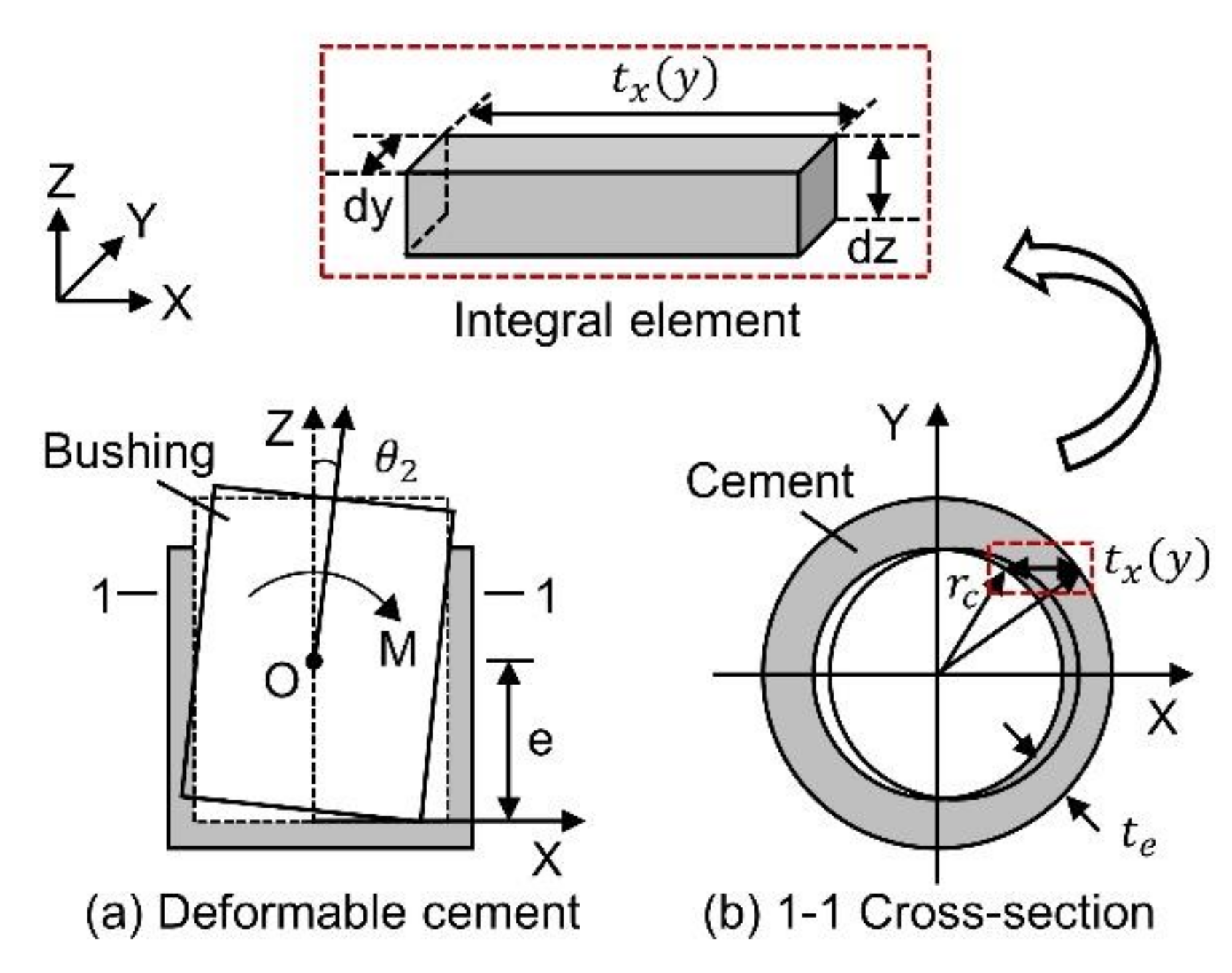
eHeight of the center of rotation (m), see Figure 3
Ecelastic modulus of porcelain bushing (N/m2)
Efelastic modulus of flange (N/m2)
Egelastic modulus of the cement bond (N/m2)
hcheight of the cement bond in the flange (m)
Iccross-sectional moment of inertia of the porcelain bushing (m4)
Ifupper section moment of inertia of the flange (m4)
Kcbending stiffness of the joint (N∙m/rad)
Kc1bending stiffness of the porcelain bushing (N∙m/rad)
Kc2bending stiffness of the cement bond (N∙m/rad)
Kc3bending stiffness of the flange member ring wall (N∙m/rad)
kztotal elastic stiffness coefficient
Lcequivalent length of the porcelain bushing (m)
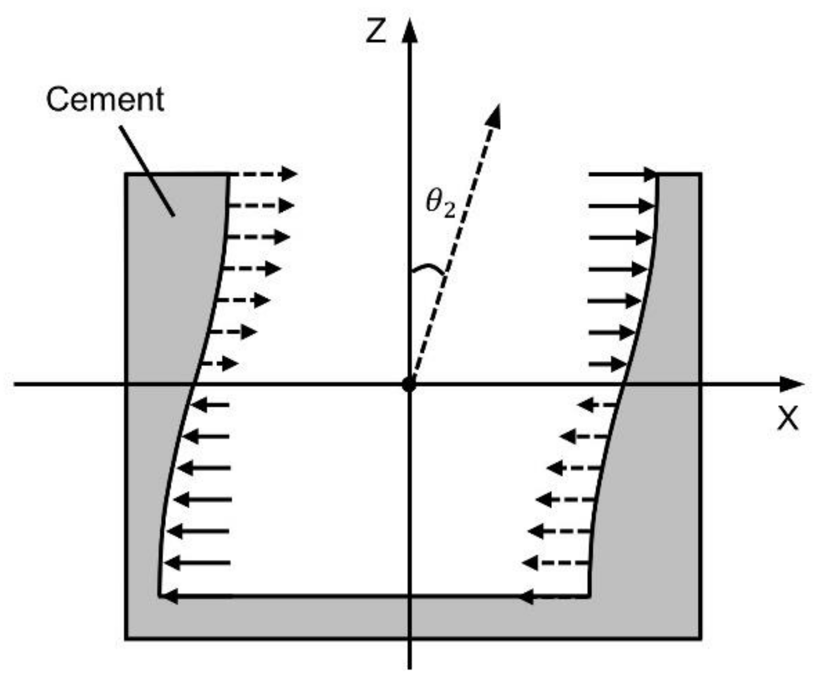
Msum of the moments of the adhesive side wall compression force (N∙m)
rcradius of the porcelain bushing (m)
tethickness of the cement filling between the flange and the porcelain bushing (m)
U1bending deformation strain energy of the porcelain bushing (J)
U2elastic strain energy of the cement bond (J)
Wthe work performed by the bending moment load (J)
W(e)strain energy of the adhesive side wall compression force (J)
𝛼customized parameter, see Equation (23)
βan empirical parameter
𝛾customized parameter, see Equation (11)
θdeformation of the flange and porcelain bushing connecting joint (rad)
θ1porcelain bushing bending deformation (rad)
θ2cement mortar extrusion deformation (rad)
θ3flange member ring wall bending deformation (rad)
𝜆customized parameter, see Equation (12)
μelasticity coefficient
Πtotal potential energy of the porcelain bushing structure after deformation (J)

References

  1. Liu, R.; Zhang, M.; Wu, Y. Vulnerability study of electric power grid in different intensity area in Wenchuan earthquake. In Proceedings of the 15th World Conference of Earthquake Engineering (WCEE), Lisboa, Portugal, 24–28 September 2012. [Google Scholar]
  2. Johnson, F.; Iliev, K. Earthquake effects on SDG&E’s 500/230 kV Imperial Valley Substation. In Proceedings of the 2012 IEEE Power and Energy Society General Meeting, San Diego, CA, USA, 22–26 July 2012; pp. 1–2. [Google Scholar]
  3. Tang, A.K.; Eidinger, J.M. Chile Earthquake of 2010: Lifeline Performance; American Society of Civil Engineers: Reston, VA, USA, 2013. [Google Scholar]
  4. Liu, R.; Liu, J.; Yan, D.; Ye, F.; Lin, J.; Li, J. Seismic damage investigation and analysis of electric power system in Lushan Ms 7.0 earthquake. J. Nat. Disasters 2013, 22, 83–90. [Google Scholar]
  5. Liu, Z.; Dai, Z.; Lu, Z. Weibull distribution based seismic vulnerability analysis of porcelain equipment. Power Syst. Technol. 2014, 38, 1076–1081. [Google Scholar]
  6. Liu, C.; Wang, C.; Long, M.; Zha, C. Study of seismic response and vibration control of High voltage electrical equipment damper based on TMD. Sci. Technol. Eng. 2016, 157, 012027. [Google Scholar] [CrossRef]
  7. Zareei, S.A.; Hosseini, M.; Ghafory-Ashtiany, M. Evaluation of power substation equipment seismic vulnerability by multivariate fragility analysis: A case study on a 420 kV circuit breaker. Soil Dyn. Earthq. Eng. 2017, 92, 79–94. [Google Scholar] [CrossRef]
  8. Zhu, Z.; Zhang, L.; Cheng, Y.; Guo, H.; Lu, Z. On the Nonlinear Seismic Responses of Shock Absorber-Equipped Porcelain Electrical Components. Math. Probl. Eng. 2020, 2020, 9026804. [Google Scholar] [CrossRef]
  9. Liu, J.; Wang, Y.; Han, W. Review on seismic disaster analysis and aseismatic measures of transformer substation. Electr. Power Constr. 2011, 32, 44–50. [Google Scholar]
  10. Xie, Q.; He, C.; Yang, Z.; Wen, J. Tests and Analyses on Failure Mechanism of 1100 kV UHV Transformer Porcelain Bushing. High Volt. Eng. 2017, 43, 3154–3162. [Google Scholar]
  11. Zareei, S.A.; Hosseini, M.; Ghafory-Ashtiany, M. Seismic failure probability of a 400 kV power transformer using analytical fragility curves. Eng. Fail. Anal. 2016, 70, 273–289. [Google Scholar] [CrossRef]
  12. Lee, S.-Y.; Ko, K.-H.; Lee, J.M. Analysis of dynamic characteristics of structural joints using stiffness influence coefficients. KSME Int. J. 2000, 14, 1319–1327. [Google Scholar] [CrossRef]
  13. Lavassas, I.; Nikolaidis, G.; Zervas, P.; Efthimiou, E.; Doudoumis, I.; Baniotopoulos, C. Analysis and design of the prototype of a steel 1-MW wind turbine tower. Eng. Struct. 2003, 25, 1097–1106. [Google Scholar] [CrossRef]
  14. Xie, Q.; Hao, J.; Zhang, W.; Ding, Y.-Y.; Li, M.; Lin, S.; Zhang, Y.-M. Comparative study on porcelain insulators design for high-voltage electric equipment at home and abroad. Insul. Surge Arresters 2010, 2, 15–20. [Google Scholar]
  15. GB 50260-2013; Code for Seismic Design of Electrical Installations. China Planning Press: Beijing, China, 2013.
  16. JEAG 5003-1980; Seismic Design Guidelines for Electrical Equipment. Standards Press of China: Beijing, China, 1984.
  17. Cao, M.; Cheng, Y.; Dai, Z.; Lu, Z.; Zhou, F.; Tan, P. Study of seismic performance and damping effects of porcelain column circuit breaker SF6. Eng. J. Wuhan Univ. 2009, 1, 267–272. [Google Scholar]
  18. Zhu, Z.; Dai, Z.; Lu, Z.; Zhang, X.; Gao, P. Experimental study of the bending rigidity at flange connection of UHV electrical equipment. Electr. Power 2014, 47, 6–11. [Google Scholar]
  19. Yuhan, S.; Zhicheng, L.; Zhenlin, L. Earthquake simulation shaking table test for 1100 kV UHV bushing. High Volt. Eng. 2017, 43, 4139–4144. [Google Scholar]
  20. He, C.; Xie, Q.; Zhou, Y. Influence of flange on seismic performance of 1100-kV ultra-high voltage transformer bushing. Earthq. Spectra 2019, 35, 447–469. [Google Scholar] [CrossRef]
  21. Xue, Y.; Cheng, Y.; Zhu, Z.; Li, S.; Liu, Z.; Guo, H.; Zhang, S. Study on seismic performance of porcelain pillar electrical equipment based on nonlinear dynamic theory. Adv. Civ. Eng. 2021, 2021, 8816322. [Google Scholar] [CrossRef]
  22. Zhang, X.; Dai, Z.; Zhicheng, L.U.; Cao, M. Coefficient of bending stiffness of interconnected parts between ultra-high voltage porcelain bushings and flanges. Eng. J. Wuhan Univ. 2014, 47, 794–799. [Google Scholar]
  23. Gao, Z.; Zhu, Q.; Yang, Q.; Cao, M. Study on Bending Stiffness of Interconnected Part Between High Voltage Porcelain Bushing and Flange. Insul. Surge Arresters 2018, 184–189. [Google Scholar] [CrossRef]
  24. Huang, Y.; Zhao, X.; Chen, S. Rayleigh-Ritz method in elastic dynamics. J. Hebei Inst. Technol. 1996, 62–66. Available online: https://kns.cnki.net/kcms/detail/detail.aspx?dbcode=CJFD&dbname=CJFD9697&filename=HBLG602.018&uniplatform=NZKPT&v=nRFEvR5lgf9x5s968OncmtSvruS1JJFee2xGtiymIbClVnp-stTT1udqFdUKqRFA (accessed on 10 April 2022).
  25. Zhang, P. Energy Theory in Structural Mechanics; Shanghai Scientific and Technical Publishers: Shanghai, China, 2010. [Google Scholar]
Figure 1. Interconnection between UHV porcelain bushing and flanges.
Applsci 12 05899 g001
Figure 2. Joint connecting the porcelain bushing and flange. (a) Bending deformation of the flange and porcelain bushing connecting joint; (b) Porcelain bushing bending deformation; (c) Cement mortar extrusion deformation; (d) Flange member ring wall bending deformation.
Applsci 12 05899 g002
Figure 3. Deformation of the cement bond.
Applsci 12 05899 g003
Figure 4. Deformation of the porcelain bushing.
Applsci 12 05899 g004
Figure 5. Contact forces on the cement.
Applsci 12 05899 g005
Figure 6. Ultra-high voltage porcelain bushings.
Applsci 12 05899 g006
Figure 7. Fitted curve of the elasticity coefficient, μ.
Applsci 12 05899 g007
Figure 8. Comparison of bending stiffness results.
Applsci 12 05899 g008
Figure 9. Ultra-high voltage lightning arresters.
Applsci 12 05899 g009
Figure 10. Comparison of calculation results.
Applsci 12 05899 g010
Table 1. Specimen size properties (Unit:mm).
Specimen123456789
Outside diameter, dc130130140160205245275375500
Inside diameter, db 808080105125145175275420
Bushing length126512751365138516151615187525002650
Cement height, hc6055606585100110170230
Cement thickness, te1091010107.57.5910
Outside diameter, Df192190202224252304348456580
Inside diameter, df150148160180225260290393520
Table 2. Elasticity coefficient, μ.
SpecimenExperiment
(×106 N∙m∙rad−1)
Equation (3)
(×106 N∙m∙rad−1)
Elasticity
Coefficient, μ
12.973.610.77
22.843.200.86
33.364.030.79
44.615.800.74
59.1614.190.55
620.9531.510.54
727.750.160.44
857.6146.640.22
9133317.030.19
Table 3. Variation in the elasticity coefficient, μ, with the cement height.
SpecimenCement Height, hc (mm)Elasticity Coefficient, μ
1600.77
2550.86
3600.79
4650.74
5850.55
61000.54
71100.44
81700.22
92300.19
Table 4. Bending stiffness, Kc (Unit: ×106 N∙m∙rad−1).
SpecimenDiameter, dc (mm)Height,
hc (mm)
Experimental
Result
Equation (1)
β = 6.54 × 10⁷
Equation (1)
β = 5.00 × 10⁷
Equation (27)
1130602.973.06 (+3.05%)2.34 (−21.21%)3.02 (+1.83%)
2130552.842.86 (+0.62%)2.18 (−23.07%)2.76 (−2.69%)
3140603.363.30 (−1.90%)2.52 (−25.0%)3.35 (−0.31%)
4160654.614.42 (−4.10%)3.38 (−26.68%)4.61 (+0.03%)
5205859.169.69 (+5.75%)7.41 (−19.15%)9.80 (+6.99%)
624510020.9521.36 (+1.98%)16.33(−22.04%)19.85 (−5.26%)
727511027.7029.02 (+4.75%)22.18 (−19.9%)27.97 (+0.99%)
837517057.6078.75(+36.72%)60.21 (4.53%)56.40 (−2.08%)
9500230133.0172.98(+30.06%)132.25(−0.56%)134.59(+1.20%)
Table 5. Geometric parameters of typical ultra-high voltage electrical equipment.
ParameterArrester 1Arrester 2
Outside diameter, dc (mm)510600
Inside diameter, db (mm)400500
Bushing length (mm)21152350
Cement height, hc (mm)200200
Cement clearance, te (mm)1020
Outside diameter, Df (mm)590700
Table 6. Comparison of calculation results (Unit: N∙m∙rad−1).
ParameterArrester 1Arrester 2
Equation (1), β = 6.54 × 1071.33 × 1087.85 × 107
Equation (27)1.05 × 1086.80 × 107
Equation (1), β = 5.00 × 1071.02 × 1086.00 × 107
Publisher’s Note: MDPI stays neutral with regard to jurisdictional claims in published maps and institutional affiliations.

